Abstract
A digital proportional valve is constituted by the main spool and a high-speed on/off valve bridge acting as the pilot stage. However, the main spool will generate oscillation during movement under the control of the pilot stage. This results in poor stability, slow response speed, low control accuracy, and even the potential loss of control of the valve. To tackle this issue, an oscillation suppression method based on fuzzy intelligent proportional-integral-derivative (PID) control is put forward. The movement state of the main spool is determined in accordance with its movement position and velocity. Thereafter, the fuzzy control parameters of the controller are calculated on the basis of the determined movement state of the main spool. Different PID parameters are adopted to eliminate the control effect difference caused by the structural asymmetry of the two pilot control chambers of the main valve. The performance and robustness of the proposed control method are verified by comparison with the PID controller based on full-bridge and half-bridge control. The results demonstrate that the proposed control method can effectively suppress the oscillation of the main spool of the digital proportional valve, improve the control accuracy, and reduce the response time. When the excitation signal takes the form of a step signal, the overshoot of the control method put forward in this paper is diminished by 26.2% in comparison with that of the PID control. Under stable operating conditions, the maximum tracking error is less than 3.1%. Moreover, compared with simply using the PID control method, this error is reduced by 41%.
1. Introduction
Traditional proportional valves utilize proportional electromagnets as electromechanical conversion elements to control the movement of valve spools, which gives rise to issues such as high cost, sensitivity to oil pollution, and low reliability. By contrast, digital proportional valves (DPV) with high-speed on/off valves (HSV) serving as the pilot part possess merits such as strong anti-pollution capability, high reliability, convenient manufacture, and flexible control. Moreover, as the core control element in the intelligent development of hydraulic systems, HSV has excellent application prospects.
Several studies have employed proportional valves and systems with HSV as control components. In the mid-1990s, Eaton [1,2] developed the Hydraulic Feedback Valvistor, a two-way cartridge proportional flow valve that uses a pulse width modulation (PWM) signal to control the two-position four-way proportional valve as the pilot section. Parker [3] developed the VPL series proportional valves, which use two two-position three-way HSV as the pilot section to control the movement of the main spool. Danfoss [4] developed PVG series proportional multi-way valves, comprising four HSV as the pilot section to control the pressure of the two control chambers of the main spool. SIL/PL, developed by Atos company, is a new DPV based on the bus [5]. Zhu et al. [6] designed a water-hydraulic DPV, in which eight HSV with pulse width modulation are used as the pilot section to control the movement of the main spool. Prof. Wei’s research group studied the proportional valve controlled by the high-speed on/off valve bridge (HSVB) based on ARM and proposed the PWM complementary control method between the two half-bridges of the HSV [7]. Adeli et al. [8] studied the hydraulic cylinder position system controlled by two two-position three-way HSV and proposed a sliding mode control algorithm to suppress the un-certain factors in the model. Gao et al. [9,10] designed an adaptive robust control method for a hydraulic cylinder controlled by HSV and directional valve. Meng et al. [11] used four pneumatic HSV to control the cylinder and adopted an adaptive robust controller considering the influence of viscosity and Coulomb friction, and the experimental error was less than 2.4%.
Patrick Opdenbosch et al. [12] studied the intelligent control method of the wheatstone valve bridge composed of four poppet valves. Tampere University of Technology used four groups of twenty threaded cartridge on/off valves to control the actuators and achieve more energy-saving flow control [13]. Lin et al. [14] used a hybrid control method to regulate the pressure system controlled by the HSVB in real time. Purdue University in the United States used a combination of five poppet valves to study a robust adaptive control strategy and realize trajectory tracking control and energy-saving control [15]. Hunan Intelligent Digital Hydraulic Valve Company (Liling, China) has developed IDP series load-sensing proportional multi-way valves with the on/off type [16].
Evidently, considerable research has been conducted on the structure of the proportional valve with HSV as the pilot section and the hydraulic cylinder position system with HSV as the control element. However, the control method of the proportional valve controlled by four HSV as the pilot bridge, as well as the method of suppressing oscillation of DPV, have not been adequately investigated. Zamani et al. [17,18,19,20,21,22] developed a series optimal intelligent control approach for seismic control of buildings equipped with active hybrid energy storage management in a wind-dominated standalone system, which combined classic PID control with intelligent control technology and represents more efficient control performance and robustness.
In addition, we have noticed that the fuzzy intelligent PID control method has also been utilized in other fields. Nasir, NM et al. [23] combined fuzzy logic control and Particle Swarm Optimization algorithm with the neural network model to enhance the stability and performance of two-wheeled wheelchair systems. Nelson Luis Manuel et al. [24] analyzed the performance of five algorithms, namely Equilibrium Optimizer (EO), Particle Swarm Optimization (PSO), Teaching-Learning-Based Optimization (TLBO), Differential Evolution (DE), and Genetic Algorithm (GA), in fine-tuning the gains of a proportional-integral-derivative (PID) controller to control the speed of a DC motor. All of these five algorithms are able to provide the optimal gains, but their performance is inferior to that of the Fuzzy Logic Controller. Fan A et al. [25] proposed taking the parallel hybrid ship as the research object. They designed the two-layer fuzzy logic control strategy, the dynamic programming algorithm, and the improved fuzzy logic control strategy using Simulink. Then, co-simulation validation was carried out from multiple aspects. The results showed that the improved fuzzy logic control strategy can achieve energy conservation and emission reduction and also ensure real-time stability.
In the process of investigating the DPV with the HSVB as the pilot section, it was found that the existing control methods will cause large pressure fluctuations in the two pilot control chambers of the main valve during the positioning process. This in turn will cause high-frequency oscillation in the main spool, leading to the reduction in control accuracy and stability of DPV. Suid and Ahmad have proposed a SPID controller optimized by NSCA for AVR applications, showing excellent stability and frequency response characteristics in contrast to traditional PID controllers. Although the control method proposed by Suid and Ahmad has demonstrated remarkable control efficacy when applied to the AVR system, the control performance of the SPID controller may not be as outstanding for complex time-varying systems [26]. The fractional PID controller has drawbacks such as difficult parameter tuning due to the increased number of parameters compared to the classical PID controller, the complexity of tuning in the non-linear version with eight parameters, potential instability when the order exceeds 2, and limitations in handling extremely complex systems and being restricted by practical conditions in some applications [27]. The existing data-driven neuroendocrine-PID using SPSA as the tuning/optimization tool has disadvantages like inability to find the optimal value due to memory-less optimization, possible un-stable convergence, step size dependence on gain sequences that decrease with more iterations, and lacking energy to readjust step size for new optimal solutions when disturbances, etc., occur during tuning [28]. The BELBIC, based on information from the feedback loop of the reference signal tracking system, shows a high learning ability to develop an appropriate control action with low computational complexity [29]. The physical system under investigation in this paper exhibits a high degree of non-linearity, time-variability, and un-certainty. Certain factors may also undergo alterations in accordance with the passage of time and variations in the operating conditions. For instance, the variation in the coil temperature of the HSV can exert an impact on its resistance and capacitance, along with the fluctuations in the oil supply pressure of the pilot stage, and so forth. The fuzzy PID controller is capable of handling such intricate relationships by means of fuzzy rules. Consequently, the fuzzy intelligent PID controller is selected.
Aiming at this problem, an oscillation suppression method based on fuzzy intelligent proportional-integral-derivative (PID) control is proposed in this study, which can effectively suppress the spool oscillation, improve the response speed and control accuracy of the main spool, and provide a guarantee for the wide application of DPV.
2. Mathematical Model of Proportional Valve with HSVB as Pilot Section
2.1. Structure and Working Principle
Figure 1 shows the structure and working principle of the DPV with HSVB as the pilot valve.
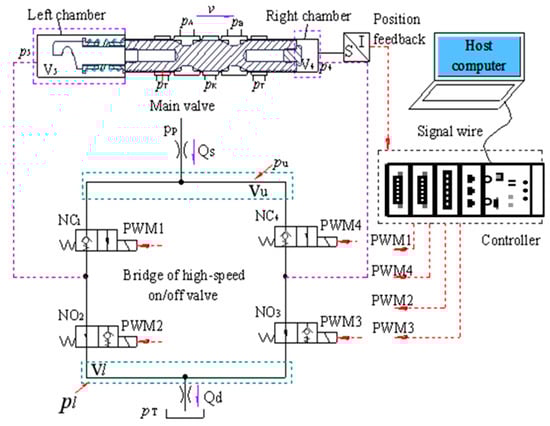
Figure 1.
Schematic and working principle of the DPV.
The valve mainly includes a controller, a pilot valve bridge composed of four HSV, which include two normally closed valves (NC1 and NC4) and two normally open valves (NO2 and NO3), and a main valve. The controller outputs four PWM signals with different duty cycles that adjust the on/off time and frequency of four HSVs and control the flow and pressure in the left and right chambers, and then, control the movement of the main spool. The spool displacement sensor is used to detect and feedback the displacement of the main spool in real time to form a closed-loop control, so as to accurately control the flow rate through the main valve.
2.2. Main Valve Model
Assuming that the right side is the positive direction of the spool movement, according to the working principle of the DPV shown in Figure 1, the force balance equation of the main spool can be obtained as follows:
A5 represents the effective area in the left control chamber of the main spool, while p5 represents the pressure in the same chamber. A4 represents the effective area in the right control chamber of the main spool, and p4 represents the pressure in the right control chamber of the main spool. K represents the spring rate, and x0 represents the pre-compression. Ff is the friction force acting on the spool. The viscous damping coefficient is Bx. Fsh1 represents the flow force on the spool when the hydraulic fluid flows from the pressure port to the load, and Fsh2 represents the flow force on the spool when the hydraulic fluid flows from the load to the oil return port. Cv is the flow velocity coefficient, while Cd is the flow rate coefficient. The valve port flow area is axm. The inlet pressure of the main valve is pK. The pressure in port A of the load is pA, the pressure in port B of the load is pB, and the pressure of the oil return port is pT. The mass of the main spool is m, and the displacement of the main spool is xm. The effective areas at both ends of the main spool are equal, so A4 and A5 are equal. θ1 represents the jet angle of the flow from the pressure port towards the load, and θ2 represents the jet angle of the flow from the load towards the oil return port. The valve port arrangement is shown in Figure 2. The angles of θ1 and θ2 can be acquired in the following way with reference to Figure 2.
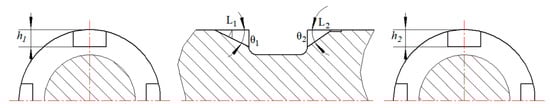
Figure 2.
Slot arrangement and angle.
2.3. Model of HSVB
From the structure of the HSVB, it can be observed that the valve bridge has four oil ports: pilot oil inlet port (pp), oil return port (pT), left control oil port (p5), and right control oil port (p4). When the valve bridge is in operation, the pilot oil inlet port (pp) can supply a certain amount of pressure and flow rate. Through the special matching relationship of the HSVB, the fluid can flow into the left control oil port as well as the right control oil port, thus achieving the continuous proportional flow control of the main valve.
According to the hydraulic circuit of the HSVB in Figure 3, considering the oil compressibility, the main spool’s leakage clearance, and the pipeline volumes from the pilot oil source to the HSV inlet and from the HSV outlet to the tank, the flow rate continuity equation of each node is established as Equation (3).
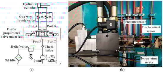
Figure 3.
Test bench of DPV: (a) Schematic diagram; (b) Physical diagram of the experimental system.
QS and Qd are the flow rates at the inlet and outlet of the HSVB, respectively. As and Ad are the flow areas of the throttle valves in the oil inlet and return paths. QNCn and QNOn are the flow rates through the four HSV. D is the envelop diameter of the main valve. Cr is the leakage clearance from the main valve control chamber to port T. L is the clearance length. Vu and Vl are the pipeline volumes from the pilot oil source to the inlet of the HSV and from the outlet of the HSV to the tank, respectively. β is the bulk modulus of the hydraulic fluid. pu and pl are the inlet and outlet pressures of the HSVB. V5 and V4 are the volumes of the left and right control chambers of the main spool, respectively. Dn is the duty cycle of the HSV. An is the cross-sectional area of the HSV, and Δpn is the pressure drop between the inlet and outlet of the HSV.
The following is the way to express the dynamic equation of the DPV.
3. Spool Oscillation Experiment
The test bench of DPV with HSVB as the pilot section was built as shown in Figure 3. Figure 3a is the schematic diagram, and Figure 3b is the physical diagram of the experimental system, which includes a measurement and control system, hydraulic pump station, hydraulic cylinder, and DPV under test. The measurement and control system includes a host computer, NI CompactRIO embedded controller, sensors, NI 9203 AI card, and NI 9401 DIO data acquisition card. These equipment were purchased in Lanzhou, China. The displacement sensor was used to acquire the displacement of the main spool, the pressure sensor was used to obtain the pressure of the control chamber on the right side of the main spool, and the temperature sensor was used to obtain the temperature of the control chamber. The temperature in the control chamber was 3 degrees Celsius. By adopting the existing position-based full bridge compensation control method, the experimental results of the displacement step response of the main valve spool, as shown in Figure 4 can be obtained.
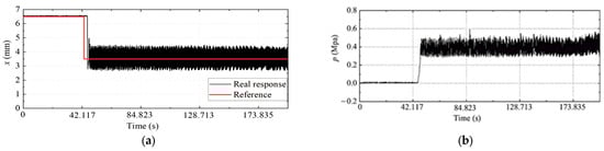
Figure 4.
Step response of main spool displacement: (a) Step response of actual displacement; (b) pressure of main spool control chamber.
As can be observed from Figure 4, oscillations occur during the movement of the main spool, and the smaller the displacement is, the more prone it is to oscillate. In the existing control methods, when the opening of the main spool is small, the control input of the HSVB fluctuates significantly, which will cause the pressure to fluctuate in the two pilot control chambers. Consequently, the main spool will exhibit relatively large oscillations, thereby giving rise to rather prominent issues regarding response delay and stability. As depicted in Figure 4, the response delay time of the main spool under the existing control method is approximately 2.144 s. In view of this, this study proposes an oscillation suppression method based on fuzzy intelligent proportional-integral-derivative (PID) control.
4. Control Method Design
Based on the above theoretical analysis, a control method based on fuzzy intelligent PID is proposed, which predicts the movement trend of the main spool according to the movement direction, position error, and error change rate and adjusts the control signal of the HSVB in real time. Therefore, the pressure of the two control chambers of the main spool can follow a change in the input state. A displacement sensor is used to detect the displacement of the main spool and form closed-loop feedback control. The position error is calculated based on the expected and feedback values, and the position error is converted into four different duty cycle signals by using a fuzzy intelligent PID control algorithm to control the combined motion of HSV. Thus, the flow rate and pressure in the pilot control chamber of the main spool are controlled by the HSVB, and the main spool is pushed to the expected position. Figure 5 shows the control structure block diagram of the DPV with four HSVs as the pilot section.
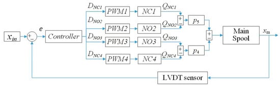
Figure 5.
Control structure block diagram of the DPV.
4.1. Input Signal and Displacement
The input signal defines the expected position of the main spool. As shown in Figure 1, the main spool is driven by four HSVs with different duty cycles. The stroke of the main spool is −7.5–7.5 mm, and the duty cycle input range of the HSV is 0–1. Based on this, the linear relationship between the displacement of the main spool and the duty cycle of the HSV can be obtained, as expressed in Equation (5).
where Dn (t) is the duty cycle of HSV. The relationship between the position error and the input position is expressed as follows:
where e (t) is the error of the spool input position and actual position, xin (t) is the input position, and xt (t) is the measured actual position.
4.2. Fuzzy Intelligent PID Controller Design
The structure of control chambers at both ends of the main spool of the DPV is asymmetric, which produces different control effects in different movement directions. By optimizing the existing full-bridge-based control methods, the following half-bridge-based fuzzy intelligent PID control method is proposed.
The parameters of fuzzy logic include the universe of discourse of input and output variables, fuzzy sets and membership functions, the fuzzy rule base, and the defuzzification method. The universe of discourse of input and output variables is set according to the specific parameters of the system. For the fuzzy sets and membership functions, the methods commonly used in literature and textbooks are adopted. There is a total of seven intervals for the fuzzy sets (NB, NM, NS, ZO, PS, PM, and PB). When NB and PB are at the maximum error, the stable and smooth Gaussian function is used, and for the others, the triangular membership function with higher sensitivity is used. The fuzzy rule base is designed based on experience and the system. The commonly used centroid method is chosen as the defuzzification method because it takes comprehensive information into account, the output results are relatively smooth, it has relatively high accuracy, and it is applicable to various types of membership functions.
We have already opened or closed different HSVs according to the variations in input signals and errors. The usage details of the four HSVs are presented in Table 1. Additionally, to enhance the control accuracy, different control parameters are employed when the main spool moves in different directions.

Table 1.
Switching combinations of HSVs.
The fuzzy intelligent PID control rule is designed as follows:
where Kp, Ki, and Kd represent the initial parameters of PID, and fkp, fki, and fkd represent the three output parameters of a fuzzy intelligent controller.
The fuzzy intelligent controller takes the position error e (t) and the error change rate de (t)/dt of the main spool as input parameters and takes three PID adjustment parameters fkp, fki, and fkd as outputs. The position error and error change rate of the main spool were quantified into fuzzy domains E [−1,1] and EC [−6,6], respectively.
Assumption 1.

ei and eci are uniformly distributed regular convex fuzzy sets on domains E and EC, which are described by seven linguistic values. Their membership functions are stable and smooth Gaussian functions when the E and EC are NB and PB, and they are all trigonometric functions in other cases. The membership function is shown in Figure 6.
Figure 6.
The membership function of E.
Assumption 2.

fkp, fki, and fkd are described by seven linguistic values. Their membership functions are all Gaussian functions, as shown in Figure 7.
Figure 7.
The membership function of fkp.
Based on the above assumptions, the implication relationship between each rule is as follows:
Fuzzy rules are determined based on experience and system requirements. When the position deviation E of the main valve spool is large and the deviation rate EC is small, fkp is relatively large, while fki and fkd are relatively small, aiming to accelerate the system response speed. When E is large and the deviation rate EC is also large, fkp and fkd are relatively small and fki is relatively large, with the purpose of reducing the overshoot. When E is small and EC is large, fkp is relatively small and fki is relatively large to enhance the system’s steady-state performance. When both E and EC are small, fkd is relatively large to speed up the response and improve the system’s steady-state performance. The fuzzy rule base is designed as shown in Table 2.
Table 2.
The fuzzy rule base.
The fuzzy quantities of fkp, fki, and fkd were obtained using fuzzy control rules, and the accurate values of fkp, fki, and fkd were calculated by the area center method. The values of fkp, fki, and fkd are shown in Figure 8.

Figure 8.
Value rules of fkp, fki, and fkd: (a) Value rule of fkp; (b) value rule of fki; (c) value rule of fkd.
Obviously, fkp is larger when E is larger and EC is smaller, fki is larger when E is smaller and EC is larger, and fkd is larger when E is smaller.
Considering the main spool displacement change rate dx (t)/dt as the control condition, when dx (t)/dt ≥ 0, a smaller proportional coefficient is adopted, and when dx (t)/dt < 0, a larger proportional coefficient is used.
Figure 9 shows the structural block diagram of the fuzzy intelligent PID controller.

Figure 9.
Structural block diagram of the fuzzy intelligent PID controller.
The specific control flowchart of the DPV is shown in Figure 10.
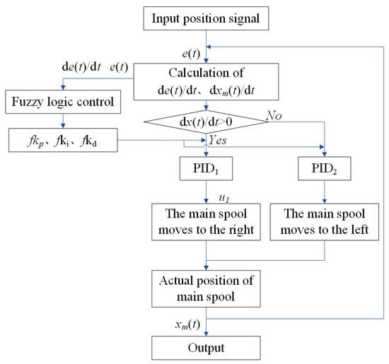
Figure 10.
Control flowchart.
5. Simulation Results and Discussion
Using Amesim 2016 and MATLAB/Simulink 2015b co-simulation technology, the DPV model shown in Figure 11 was built in Amesim, and the fuzzy intelligent PID controller was established in MATLAB/Simulink. The Euler method was used to discrete the continuous signal of a closed-loop system, and the sampling time was set to 0.001 s, and the simulation parameters are listed in Table 3. Considering the control stability, accuracy, and rapidity, the initial PID parameters are considered as Kp1 = 2.5, Ki1 = 0.1, Kd1 = 0.05, Kp2 = 1, Ki2 = 0.05, and Kd2 = 0.05, which represent two groups of proportional, integral, and differential gains, respectively.

Figure 11.
DPV model in Amesim.
Table 3.
Simulation parameters.
5.1. Effectiveness Analysis
To verify the effectiveness of the proposed DPV control method, firstly, the valve was simulated and analyzed under the no-load condition, and the pressure compensation valve was ignored in this case.
5.1.1. Step Input Response
When the reference displacement is a step input of 7–3.5 mm, the step response of the DPV is measured, and the results are shown in Figure 12. We have observed that the step response curve under the position-based full-bridge compensation control method depicted in Figure 12a coincides with the experimental results presented in Figure 4a. This demonstrates that the simulation results are reliable and can be utilized for subsequent simulation analysis.
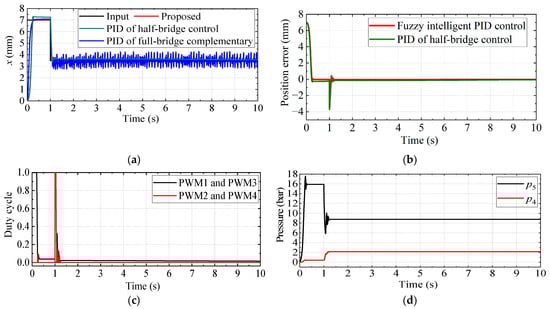
Figure 12.
Step response of the proportional valve: (a) Displacement step response of the main valve spool; (b) displacement tracking error; (c) control input of HSVB; (d) pressure of the two control chambers of the main spool.
As shown in Figure 12, the main spool produces oscillation at the position of 3.5 mm in the control of full-bridge complementary method, while oscillation disappeared in the control of half-bridge method, and the main spool shows a better performance of the proposed controller than the PID controller. For comparison purposes, the response results of step input from 0 mm to 7 mm are summarized for the performance indices shown in Table 4. As we can see from Figure 12, the proposed control method can respond to the input signal quickly when the position error occurs. At the initial stage, the position error is a larger value in the positive direction, so that the HSV 1 and 3 have a larger duty cycle, and the pressure in the left chamber (p5) rises rapidly; therefore, the spool moves to the position of 7 mm. When receiving a stepping input signal of 3.5 mm, the HSV 2 and 4 have a larger duty cycle control signal, and the pressure on the right side of the main spool increases and the left side reduces. The main spool is pushed and stabilized at the desired position after a short adjustment time. Then, the oscillation is suppressed.
Table 4.
Performance indices for the studied valve subjected to the step input response.
As can be seen from the simulation results summarized in Table 4, it is concluded that the rising time for the proposed method is 121 ms, which is longer than PID of half-bridge control, while the steady state error is 0.016 mm, which is much less than PID of half-bridge control of 0.243 mm, and a reduction of 26.2% is obtained in the overshoot for the proposed method. In addition, we have carried out an integral square error (ISE) analysis of the proposed control method and the PID of half-bridge control method within the time interval from 3 s to 5 s, and the results are presented in the last column of Table 4. The tracking error of the proposed method is significantly smaller than that of the traditional PID control method, suggesting that the proposed method exhibits a more precise and reliable tracking performance for step inputs.
In summary, compared with the full-bridge control methods, the proposed half-bridge-based fuzzy intelligent PID control can quickly predict and adjust the control signals of the four HSV according to the position error and error change rate, so that the pressure in the left and right control chambers of the main spool can be quickly balanced. The proposed control method can suppress the oscillation of the main spool of the proportional valve for the step response.
5.1.2. Sinusoidal Input Tracking Response
To verify the dynamic response performance of the proposed method to sinusoidal input, the reference input x (t) = 3.5 sin (0.5π × t) was used. The controller parameters are the same as those in the step response, and the dynamic response results of the DPV are obtained, as shown in Figure 13. As is evident from Figure 13, the main spool produces irregular oscillation in the process of following the sinusoidal change signal under the existing control method. The proposed method could adjust the control input of the HSVB in real time according to the movement direction, position error, and error change rate. Therefore, the pressure in the two control chambers of the main spool can follow the input state changes, and the oscillation is suppressed effectively. The position tracking error is maintained at a relatively low level. Under stable operating conditions, the maximum tracking error is less than 3.1%. Moreover, compared with simply using the PID control method, this error is reduced by 41%. Furthermore, an integral square error analysis was conducted on the proposed control method and the PID of half-bridge control method within the time interval ranging from 3 s to 5 s, with the results presented in Table 5. When the input is a sinusoidal signal, the tracking error of the proposed method is much smaller than that of the PID of half-bridge control method. Compared with the existing control methods, the proposed method can improve the response speed and control accuracy for sinusoidal input.

Figure 13.
Sinusoidal response of the proportional valve: (a) Sinusoidal response of the main spool; (b) displacement tracking error; (c) control input of HSVB; (d) pressure of the two control chambers of the main spool.
Table 5.
Performance indices for the studied valve subjected to the sinusoidal input response.
5.1.3. Ramp Input Response
In order to further verify the effectiveness of the proposed proportional valve control method, a gradually varying ramp input was used. The response results of the DPV are shown in Figure 14.

Figure 14.
Ramp response of the proportional valve: (a) ramp response of the proportional valve main spool; (b) displacement tracking error; (c) control signal of HSVB; (d) pressure of the two control chambers of the main.
It can be observed from Figure 14 that, compared with the existing method, the proposed control method effectively suppresses the oscillation under the slowly varying input signal and exhibits a better position-tracking performance. The maximum displacement tracking error is 0.1 mm when the maximum stroke of the spool is 7 mm. As shown in Figure 14c, when the spool moves forward at a uniform speed, HSV 1 and 3 are in the working state, and HSV 2 and 4 are in the non-working state. This control method is energy-saving and efficient, which can reduce the wear of the HSV and improve the service life. As is evident from Figure 14d, as the stroke of the spool increases at a constant speed, the pressure p5 in the left chamber increases at a constant speed. With the sudden increase in the valve port area at 10.239 s, the flow force increases in a stepwise manner, and the pressure p5 in the control chamber also increases, and the main spool oscillates with a small amplitude and then quickly resumes smooth operation. This satisfies Equation. 1, which proves the effectiveness of the proposed control method.
5.2. Verification of Disturbance Rejection
To verify the disturbance rejection performance of the proposed control method, a single-rod hydraulic cylinder model was built, and the constant external load force increased from 1000 N to 3000 N at 2 s. The response results of the DPV are shown in Figure 15 when the reference position is a step input from 7 mm to 3.5 mm. Evidently, according to Equations (1)–(4), the outlet pressure of the main valve fluctuates at 2 s and rises slightly under the action of external load force, and the greater the external load force, the larger the oscillation amplitude, and the more apparent the fluctuation, the flow force produces oscillations and decreases slightly. Thus, the displacement of the main spool oscillates and increases slightly. The p5 of the control chamber pressure decreases and p4 increases to stabilize the main spool at the desired position. Therefore, the main spool reaches a stable state after a small amplitude oscillation for 0.09 s. The main spool oscillates again at 3.107 s due to the full extension of the load hydraulic cylinder and reaches a stable state after 0.035 s. Therefore, the proposed control method could suppress the oscillation of the main spool of the DPV under different load forces. The above proves that the proposed control method has good disturbance rejection performance.

Figure 15.
Step response of the proportional valve under load force: (a) Displacement step response; (b) displacement tracking error; (c) pressure of the left control chamber; (d) pressure of the right control chamber.
5.3. Analysis of Spool Oscillation
The Fourier transform results of the control results of the fuzzy intelligent controller and the full-bridge PID controller for step response are shown in Figure 16. We eliminated the vibrations with frequencies ranging from 0 to 60 Hz, which improved the oscillation of the valve spool at the steady-state position.
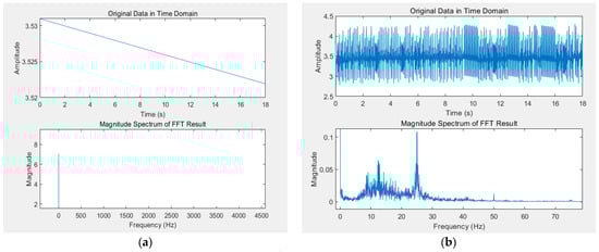
Figure 16.
The Fourier transforms of the two control methods in the steady state: (a) Fuzzy intelligent controller; (b) the full-bridge PID controller.
6. Conclusions
In the experiment, it was found that under the existing control method, the main spool of the DPV with a HSV as the pilot section oscillates during the positioning process. Thus, we investigated an oscillation-suppressing method of proportional valve based on fuzzy intelligent PID control.
At first, a detailed mathematical model of DPV was built. Then, a control method based on fuzzy intelligent PID is proposed. The method includes fuzzy control logic and a segmental PID controller. The fuzzy logic operation was performed based on the position error and error change rate of the main spool to obtain the segmental PID fuzzy control parameters. The clear values of fuzzy control quantity are calculated using the method of area center of gravity, the motion stage of the main spool is estimated according to the displacement change rate, and the control parameters are adjusted in real time to suppress oscillation of the main spool. By comparison with PID controller-based full-bridge and half-bridge, the simulation results show that the proposed method can effectively suppress the oscillation of the main spool of the proportional valve, reduce the lag, accelerate the response speed, and make the valve follow the input state better. Thus, the effectiveness and robustness of the proposed control method are confirmed.
Author Contributions
Conceptualization, N.L., L.W. and H.J.; methodology, N.L., C.D. and X.H.; software, N.L., C.D. and X.L.; validation, N.L., C.D. and X.H.; formal analysis, N.L.; investigation, C.D.; resources, L.W. and H.J.; data curation, C.D.; writing—original draft preparation, N.L.; writing—review and editing, C.D.; visualization, C.D.; supervision, H.J.; project administration, X.L.; funding acquisition, L.W. All authors have read and agreed to the published version of the manuscript.
Funding
This study was supported by the National Natural Science Foundation of China (Grant Nos. 51905243 and 52005234) and the National Key R & D Program of China (2020YFB2009800).
Institutional Review Board Statement
Not applicable.
Informed Consent Statement
Not applicable.
Data Availability Statement
The data of this paper can be obtained upon request to the corresponding author.
Acknowledgments
We sincerely thank the editors and reviewers for spending time and energy on reviewing our manuscript.
Conflicts of Interest
The authors declare no conflicts of interest.
Abbreviations
| A4 | Effective area in the right control chamber of the main spool |
| A5 | Effective area in the left control chamber of the main spool |
| p4 | Pressure in the right control chamber of the main spool |
| p5 | Pressure in the left control chamber of the main spool |
| x0 | Spring pre-compression |
| Bx | Viscous damping coefficient |
| K | Spring rate |
| Ff | Friction force on the spool |
| Cv | Flow velocity coefficient |
| Cd | Flow rate coefficient |
| Fsh1 | Flow force on the spool when the hydraulic fluid flows from the pressure port to the load |
| Fsh2 | Flow force on the spool when the hydraulic fluid flows from the load to the oil return port |
| axm | Valve port flow area |
| pK | Inlet pressure of the main valve |
| pA | Pressure in port A of the load |
| pB | Pressure in port B of the load. |
| pT | Pressure of the oil return port |
| m | Mass of the main spool |
| xm | Displacement of the main spool |
| θ1 | Jet angle from the pressure port to the load |
| θ2 | Jet angle from the load to the oil return port |
| L1,h1 | Length and depth of metering notch from the pressure port to load |
| L2,h2 | Length and depth of metering notch from load to the oil return port |
| QS | Flow rate at inlet of the HSVB |
| Qd | Flow rate at outlet of the HSVB |
| As | Flow area of the throttle valve at the oil inlet paths |
| Ad | Flow area of the throttle valve at the return oil paths |
| QNCn | Flow rate through normally closed HSV |
| QNOn | Flow rate through normally open HSV |
| D | Envelop diameter of main valve |
| Cr: | Leakage clearance from the main valve control chamber to the port T |
| L | Clearance length |
| Vu | Pipeline volume from the pilot oil source to inlet of the HSV |
| Vl | Pipeline volume from outlet of the HSV to tank |
| V4 | Volume of the right control chamber of the main spool |
| V5 | Volume of the left control chamber of the main spool |
| pu | Inlet pressure of the HSVB |
| pl | Outlet pressure of the HSVB |
| β | Bulk modulus of the hydraulic fluid |
| Dn | Duty cycle of HSV |
| An | Cross-sectional area of HSVs |
| Δpn | Pressure drop between the inlet and outlet of HSVs |
| e(t) | Error of the spool input position and actual position |
| xin (t) | Input position |
| xt(t) | Measured actual position |
| Kp | Proportional gain coefficient |
| Ki | Integral gain coefficient |
| Kd | Differential gains coefficient |
| fkp, fki, fkd | Three output parameters of fuzzy intelligent controller |
| u: | Output of controller |
| FL: | External load force |
References
- Yang, H.Y.; Wang, S.; Zhang, B. Development and prospect of digital hydraulic valve and valve control system. J. Jilin Univ. Eng. Technol. Ed. 2016, 46, 1494–1505. [Google Scholar]
- Eaton. CMA Advanced Sectional Mobile Valves E-VLVM-CC006-E3. 2021. Available online: https://www.eaton.com/us/en-us/company/news-insights/news-releases/2016/Eatons-new-cma-advanced-mobile-valve.html (accessed on 25 November 2024).
- Parker. Bulletin HY14-2109/US.USA: Parker Hannifin Corporation Hydraulic Valve Division. 2015. Available online: https://www.parker.com/Literature/Hydraulic%20Valve%20Division/hydraulicvalve/Catalog%20sections%20for%20websphere/Pulsar/Catalog%20-%20Static%20Files/Bul%20HY14-2109%20Pulsar%20Stackable%20Valves%20VP,%20VPL,%20VPO.pdf (accessed on 16 September 2024).
- Sauer-Danfoss. Proportional Valves Group PVG 32 Technical Information. 2016. Available online: https://www.danfoss.com/en/about-danfoss/our-businesses/power-solutions (accessed on 16 September 2024).
- Chen, J.; Zhang, H.X.; Zhang, X. Technical application of new digital electro-hydraulic products of Atos. Chin. Hydraul. Pneum. 2006, 87–90. [Google Scholar]
- Zhu, B.H.; Meng, J.X.; He, W. Research on the Seawater Hydraulic Proportional Valve. Chin. Hydraul. Pneum. 2013, 127–129. [Google Scholar]
- Duan, J. Research on The Controllable Amplifier of High Speed On-off Valve Bridge based on ARM. Master’s thesis, Lanzhou University of Technology, Lanzhou, China, 2016. [Google Scholar]
- Adeli, M.R.; Kakahaji, H. Modeling and position sliding mode control of hydraulic actuators using on off valve with PWM technique. In Proceedings of the International Students Conference on Electrodynamics and Mechatronics IEEE, Opol, Poland, 6–8 October 2011; pp. 59–64. [Google Scholar]
- Gao, Q.; Zhu, Y.C.; Wang, R. Adaptive robust control of electro-hydraulic position servo system using high speed on/off valve. J. Aerosp. Power 2019, 34, 503–512. [Google Scholar]
- Gao, Q.; Zhu, Y.C.; Wu, C.W. Development of a novel two-stage proportional valve with a pilot digital flow distribution. Front. Mech. Eng. 2021, 16, 420–434. [Google Scholar]
- Meng, D.Y.; Tao, G.L.; Li, A.M. Adaptive Robust Control of Pneumatic Cylinders Using Fast Switching on/off Solenoid Valves. J. Mech. Eng. 2015, 51, 180–188. [Google Scholar] [CrossRef]
- Opdenbosch, P.; Sadegh, N.; Book, W. Intelligent controls for electro-hydraulic poppet valves. Control. Eng. Pract. 2013, 21, 789–796. [Google Scholar] [CrossRef]
- Linjama, M.; Vilenius, M. Energy-efficient motion control of a digital hydraulic joint actuator. In Proceedings of the 6th JFPS International Symposium on Fluid Power, Tampere, Finland, 7–10 November 2005; pp. 640–645. [Google Scholar]
- Lin, Z.L.; Zhang, T.H.; Xie, Q. Intelligent real-time pressure tracking system using a novel hybrid control scheme. Trans. Inst. Meas. Control. 2017, 40, 1–16. [Google Scholar] [CrossRef]
- Long, G.; Lumkes, J., Jr. Comparative study of position control with 2-way and 3-way on/off electrohydraulic valves. Int. J. Fluid Power 2010, 11, 21–32. [Google Scholar] [CrossRef]
- Xu, Y.Z. Hydraulic Industry 4.0: Digitization, Networking, and Intelligence; China Machine Press: Beijing, China, 2019. [Google Scholar]
- Zamani, A.A.; Etedali, S. Seismic structural control using magneto-rheological dampers: A decentralized interval type-2 fractional-order fuzzy PID controller optimized based on energy concepts. ISA Trans. 2023, 137, 288–302. [Google Scholar] [CrossRef]
- Kord, H.; Zamani, A.A.; Barakati, S.M. Active hybrid energy storage management in a wind-dominated standalone system with robust fractional-order controller optimized by Gases Brownian Motion Optimization Algorithm. J. Energy Storage 2023, 66, 107492. [Google Scholar] [CrossRef]
- Zamani, A.A.; Etedali, S. Robust output feedback-based neuro-fuzzy controller for seismically excited tall buildings with ATMD accounting for variations in the type of supporting soil. Soil Dyn. Earthq. Eng. 2023, 164, 107614. [Google Scholar] [CrossRef]
- Etedali, S.; Zamani, A.A.; Akbari, M.; Seifi, M. A new seismic control framework of optimal PIλDμ controller series with fuzzy PD controller including soil-structure interaction. J. Frankl. Inst. Eng. Appl. Math. 2023, 360, 10536–10563. [Google Scholar] [CrossRef]
- Zamani, A.A.; Etedali, S. A new control approach for seismic control of buildings equipped with active mass damper: Optimal fractional-order brain emotional learning-based intelligent controller. Struct. Eng. Mech. 2023, 87, 305–315. [Google Scholar]
- Zamani, A.A.; Etedali, S. Optimal fractional-order PID control design for time-delayed multi-input multi-output seismic-excited structural system. J. Vib. Control. 2023, 29, 802–819. [Google Scholar] [CrossRef]
- Nasir, N.M.; Ghani, N.M.A.; Nasir, A.N.K.; Ahmad, M.A.; Tokhi, M.O. Neuro-modelling and fuzzy logic control of a two-wheeled wheelchair system. J. Low Freq. Noise Vib. Act. Control. 2024, 14613484241287608. [Google Scholar] [CrossRef]
- Manuel, N.L.; İnanç, N.; Lüy, M. Control and performance analyses of a DC motor using optimized PIDs and fuzzy logic controller. Results Control. Optim. 2023, 4, 100306. [Google Scholar] [CrossRef]
- Fan, A.; Li, Y.; Fang, S.; Li, Y.; Qiu, H. Energy management strategies and comprehensive evaluation of parallel hybrid ship based on improved fuzzy logic control. IEEE Trans. Transp. Electrif. 2023. Early Access. [Google Scholar] [CrossRef]
- Suid, M.H.; Ahmad, M.A. Optimal tuning of sigmoid PID controller using nonlinear sine cosine algorithm for the automatic voltage regulator system. ISA Trans. 2022, 128, 265–286. [Google Scholar] [CrossRef]
- Shah, P.; Agashe, S. Review of fractional PID controller. Mechatronics 2016, 38, 29–41. [Google Scholar] [CrossRef]
- Ghazali, M.R.B.; Ahmad, M.A.B.; Raja Ismail, R.M.T.B. Adaptive Safe Experimentation Dynamics for Data-Driven Neuroendocrine-PID Control of MIMO Systems. IETE J. Res. 2022, 68, 1611–1624. [Google Scholar] [CrossRef]
- Giernacki, W. Minimum Energy Control of Quadrotor UAV: Synthesis and Performance Analysis of Control System with Neurobiologically Inspired Intelligent Controller (BELBIC). Energies 2022, 15, 7566. [Google Scholar] [CrossRef]
Disclaimer/Publisher’s Note: The statements, opinions and data contained in all publications are solely those of the individual author(s) and contributor(s) and not of MDPI and/or the editor(s). MDPI and/or the editor(s) disclaim responsibility for any injury to people or property resulting from any ideas, methods, instructions or products referred to in the content. |
© 2024 by the authors. Licensee MDPI, Basel, Switzerland. This article is an open access article distributed under the terms and conditions of the Creative Commons Attribution (CC BY) license (https://creativecommons.org/licenses/by/4.0/).