Article

A New Method for 3D Dental Records Related to Orthopedic Treatments: The Hemimaxillary Plane Reference System and Its Clinical Implications

1
Department of Biomedical, Surgical and Dental Sciences, University of Milan, 20122 Milan, Italy
2
Fondazione IRCCS Cà Granda, Ospedale Maggiore Policlinico, 20122 Milan, Italy
3
Department of Biomedical Sciences for Health, University of Milan, 20133 Milan, Italy
*
Author to whom correspondence should be addressed.
Appl. Sci. 2024, 14(23), 11132; https://doi.org/10.3390/app142311132
Submission received: 18 September 2024 / Revised: 22 October 2024 / Accepted: 19 November 2024 / Published: 29 November 2024
(This article belongs to the Special Issue Advanced Studies in Orthodontics)

Abstract

:
The purpose of this explementary method study was to demonstrate, within the hemimaxillary, the three-dimensional skeletal and dental displacements of upper permanent first molars in patients undergoing rapid maxillary expansion (RME) with anchorage on deciduous teeth or paramedian miniscrews. Five post-treatment cases were analyzed on frontal and axial views before (T0) and after expansion (T1), adopting a new hemimaxillary reference system. Three-dimensional landmarks were selected to evaluate molar changes; buccal tipping and rotation were calculated, in addition to intermolar angle, molar angle of rotation, and orthopedic expansion angles. The origins (dental and/or orthopedic) of molar displacements were investigated by alternate interior angle demonstration according to the parallel lines theorem. Through inverse geometric functions of right triangles, it was possible to determine theoretical-experimental forms to calculate angles from periapical radiographs taken at T1. These findings have significant clinical implications, enabling the assessment of treatment outcomes while adhering to radioprotection principles. Reproducible formulas enable the calculation of expansion angles without CBCT. For RME to allow clinical improvement, molar rotation and intermolar angles at T1 should be less than the difference between the respective angles at T0 and the orthopedic expansion angle. This method provides a reproducible, radiation-efficient method to assess maxillary changes, enhancing treatment precision in orthodontics.

1. Introduction

Rapid maxillary expansion (RME) is an orthopedic dentofacial procedure now routinely used in early and mixed permanent dentition in cases of transverse maxillary growth deficits. In 1860, Angell introduced this orthodontic procedure with the aim of increasing maxillary transverse diameters [1]. Moreover, the biomechanical principles underlying expansion were clarified by Haas only in the late 1950s [2]. RME has subsequently been used with different protocols depending on the amount of force applied, the age of the patient, the frequency of the activations, and the duration of the treatment [3].
RME is performed using fixed devices with bands applied to the permanent upper first molars or deciduous second molars, equipped with a median screw capable of opening the suture daily by 0.25–1 mm for at least 2–6 weeks [4]. The principle behind this technique is the production of a transverse type of heavy force, which is sufficiently high to orthopedically widen the mid-palatal suture in case its ossification process is not yet completed. Along the stretched fibers of the suture, the growth of blood vessels and apposition of new bone occurs as a consequence of callus healing [5,6,7]. Suture separation actually does not occur in a parallel pattern, but there is a pyramid-like splaying of the maxillary parts with the base of the pyramid at the alveolar ridge level and the apex near the fronto-nasal suture [8]. This results in a buccal inclination of the alveolar halves carrying the teeth with them. After expansion has occurred, however, the inclination of the teeth is not equal to the alveolus one because buccal tipping of the posterior teeth also occurs. It has been reported in the literature that the average expansion in the mid-palatal suture ranges from 0.84 to 2.88 mm, accounting for 12–52.5% of the screw expansion [9], with the remaining part of the expansion being determined by precisely these dento-alveolar effects produced by strong expansion forces [10]. Because of the periodontal ligament hyalinization of the anchor teeth, the force produced by the device should ideally be transferred directly to the sutures, to increase orthopedic effects and decrease alveolar-dental effects [11]. Dental effects are particularly evident at the permanent upper first molar level and include buccal tipping, generally between 0° and 24° [12], and a disto-rotation. Understanding the dental effects generated by RME is essential as they represent an indispensable element in terms of dental problems that are not only transverse, correcting the cross-bite, but also sagittal, correcting the molar key. In fact, the disto-rotation of upper molars contributes to the correction of class II molars, improving those situations in which the transverse arch defect is sometimes associated with the abnormal rotation of these dental elements. Moreover, a rotation of the upper first molars represent an element of high clinical relevance for a correct alignment of the lower arch, as it can result in a mesial eruption of the upper first and second premolars and the subsequent appearance of precontacts with the lower arch that would prevent the physiological distal translation of the antagonists [13].
The accurate evaluation of dental and skeletal changes following RME is crucial for optimizing orthodontic treatment outcomes. Traditional methods often rely on two-dimensional imaging, which can fail to capture the complex nature of maxillary displacements. Early research in fact aimed to prove the effectiveness of maxillary expansion on skeletal and dento-alveolar structures using dental casts and two-dimensional cephalography in latero-lateral and posterior-anterior projection [14,15,16,17,18]. With the introduction of cone-beam computed tomography (CBCT) and new 3D rendering imaging techniques, it has been possible to evaluate the efficacy of RME at all three levels (skeletal, dental and alveolar) with greater precision and accuracy than previous 2D techniques [19]. To date, many studies have attempted to clinically quantify dento-alveolar effects, all following the same standard of measurement without the precise identification of reliable and stable landmarks [14,20,21,22,23,24,25]. Moreover, these studies did not justify either the origin of these effects, dento-alveolar and/or orthopedic, or whether the issue was mono- or bilateral.
As previously demonstrated [26], in order to evaluate pure dental effects, measurements within individual hemimaxillary teeth must be conducted.
The purpose of this study was to demonstrate, within the hemimaxillary, the three-dimensional skeletal and dental displacements of tipping and rotation of the upper permanent first molar in patients undergoing RME when it is performed by deciduous-tooth-borne or bone-borne anchorage via a mathematical method based on alternate interior angles.

2. Materials and Methods

An explementary method study was conducted in which possible post-expansion cases were analyzed, taking a new three-dimensional hemimaxillary reference system (represented by the plane perpendicular to the plane Ans-Pns-N and passing through the line Ans-Pns) as a stable reference, to reduce measurement bias due to three-dimensional movements of the maxillary bodies during treatment. Splitting the maxilla into two halves using the hemimaxillary plane as a reference minimizes whole-diameter bias, as the two sides (right and left) might undergo different changes. Since the Pns moves according to the orthopedic splitting of the maxilla with the corresponding half Pns, it was used as a starting point for all the derived planes (x.0; y:0; z:0). All the landmarks used in the present analysis are defined in Table 1.
The landmarks were used to obtain a 3D volumetric and surface rendering from the corresponding hemimaxilla, respectively, regarding the five different post-expansion cases analyzed and observed by different views depending on the reconstructed plane observed (Table 2). In the analysis of these, a mathematical demonstration was carried out using the angles described in Table 3. These angles were analyzed before expansion (time T0) and after expansion was completed (time T1).

3. Results

In order to individually demonstrate the three-dimensional displacements of derotation and tipping within the hemimaxillary, possible case histories are presented below.
Figure 1 represents the pre-treatment situation of the maxillary upper jaw and palatine bones, and the reference system coordinates, specifically the occlusal view (in transverse section, 1a) and the posterior view (in frontal section, 1b) of these bones. In this case, no sign of either rotation or molar tipping was observable. In fact, it was evident that angles γL and γR were equal not only to each other but also to their respective alternate interior angles (marked by *) according to the geometric theorem of parallel lines, considering the Pns-Ans segment and any line parallel to that segment. The same principle applies to the βL and βR angles, considering the centerline and any line parallel to that segment.
The opening of the medial palatine suture by RME results in the division of the maxillary upper jaw into the two hemimaxillary teeth through a pyramid-like splaying process. This phenomenon is partly responsible for the increased buccal tipping and rotation values of the first molars. Therefore, the situations that can result from such expansion are different. This study identifies and explores five example cases that may occur post-expansion, taking a stable intra-hemimaxillary plane as the reference; by analyzing them, it is possible to evaluate the angles that describe the three-dimensional movement of the upper permanent first molars.
The first case can be seen in Figure 2 in occlusal (2a) and posterior (2b) views and represents the case history in which orthopedic expansion of the maxillary upper jaw is not associated with any molar rotation or tipping (in fact, the γ and β angles remained unchanged).
An orthopedic effect, however, may be associated with a dental effect as well, either unilaterally or bilaterally, of tipping or rotation. Figure 3 shows the case where both the γ and β angles decrease () monolaterally due to distal molar rotation and buccal tipping on that side.
If, in contrast, the disto-rotation is bilateral, as in Figure 4a, the γ angle would decrease () further on both sides due to both dental and skeletal effects. Figure 4b, on the other hand, shows, in addition to the skeletal effect, bilateral buccal tipping for which the β angle decreases () compared with that of the pre-expansion condition.
Although difficult to find clinically, an additional case may be represented by a subject in which the expander results in disto-rotation/buccal tipping on one side and mesio-rotation/palatal tipping on the other (Figure 5). In such a case, if the γ and β angles of the two sides decrease () and increase (+) by the same amount, the total angles turn out to be the same as the first post-expansion case presented, in which orthopedic expansion of the upper jaw is not associated with any tooth movement.
The last case, presented in Figure 6, represents bilateral mesio-rotations (6a) and bilateral palatal tipping (6b) resulting in increased γ and β angles (+). This condition is very rare and from a dental point of view is disadvantageous. An exception where an increase in the γ angle may be favorable is class II patients undergoing extractions. To have a beneficial effect of expansion, in fact, it is necessary for the γ angle to remain the same or decrease instead. This is especially important in class IIs where in some cases disto-rotation is important for malocclusion resolution.
To refer to molar derotation is relative since it can occur by orthopedic expansion or by pure derotation; the same principle applies to molar tipping. It is possible in the figure to understand its origin by observing the alternate interior angles generated by the midlines of the respective hemimaxilla and the parallels to them. According to the geometric theorem of parallel lines, the unilateral γ and β angles result in equality with the corresponding alternate interior angles; this consideration provides a useful indication regarding the origin of the dental effects.

4. Discussion

By applying orthopedic force via RME, the opening of the median palatine suture was determined, and consequently, the division of the maxillary upper jaw into the two hemimaxillary through a process of lateral rotation, which could be partly responsible for the increased buccal tipping and rotation values of the first molars.
This study aimed to provide a rationale to guide the clinician in the right direction. Clinically, expansion is favorable if the intermolar angle and molar rotation angle of the maxillary first permanent molars at the end of expansion are more acute (thus reduced) or equal to those measured before treatment. Otherwise, if these increase, there would be molar disto-rotation or tipping, a condition that is a side effect of expansion. In fact, the clinician may realize to be directing the treatment toward an unfavorable outcome by detecting an increase in these angles. These angles must each be at least 1° greater than the orthopedic expansion angle. To achieve a favorable treatment outcome, the molar rotation angle (γ), at completed expansion (γ’), should be less than the difference between its value at time T0 and the orthopedic expansion angle.
γ < γ 0     δ
The rationale just described is also applied to the intermolar angle below, defining β0 as the intermolar angle at time T0 and β’ as the same angle at T1.
β < β 0     α
This may explain the principle behind the predictability of the post-expansion result in patients with class II subdivisions, meaning those patients with class I features on the one hand and class II features on the other [27]. This condition, which is not infrequently encountered (statistically accounting for about 50% of all class II malocclusions) and has major functional implications, is a complication of orthodontic treatment. Its etiology may be skeletal-related, dental-related, or a combination of both [28]. In the case of a dental etiology, such an asymmetrical occlusal relationship is represented by the more distal positioning of the lower first molar relative to the upper first molar on the class II side [29]. This malocclusion can also be determined by the more mesial position of the maxillary first molar relative to the mandibular first molar [30]. In such a case, a disto-rotation of the upper molar due to expansion can reestablish the correct dento-alveolar relationships, allowing sagittal class correction.
A method was analyzed to determine more precisely, for each case, the value of the orthopedic expansion angle by imagining the construction of a right-angled triangle whose cathexes are represented one by the segment between Ans and N points, and the other by the segment coinciding with the unilateral transverse expansion obtained (AnsRight-AnsLeft/2); the hypotenuse of this angle is represented by the segment between the unilateral Ans points at time T1 and N (Ans’-N). Using the inverse geometric functions of the right-angled triangle, it is possible to calculate the interior angles of the triangle, particularly the angle α, with the formula presented below.
α = 2 · a r c t g A n s R i g h t - A n s L e f t / 2 A n s - N
Imagining a further right-angled triangle whose base is again represented by the unilateral transverse expansion obtained (AnsRight-AnsLeft/2) and the height by the length of the bispinal plane (Ans-Pns), it is possible to calculate the expansion angle δ with the following formula:
δ = 2 · a r c t g A n s R i g h t - A n s L e f t / 2 A n s - P n s
These theoretical-experimental formulas can be transposed clinically by taking only an endoral periapical radiograph in the incisal area with the expander screw turns just completed (before the ossification process is achieved), which allows calculation of the transverse expansion obtained by measuring the distance between the right and left anterior nasal spines (AnsRight-AnsLeft), as well as the opening of the suture in the anterior area (Figure 7a). Instead, the N-Ans and Ans-Pns distances can be obtained from latero-lateral projection teleradiography of the skull performed at time T0; since this examination is routinely required prior to undertaking any orthodontic orthopedic treatment and since these distances are constant, there is no need to request additional post-treatment radiographic examinations from the patient with the only purpose of assessing that the molars have decompensated (Figure 7b,c).
In addition, using an intraoral scan and any measurement software, it is possible to draw the MVC and MPC points of the maxillary right and left first molar (taken as reference points considering that during treatment the anatomy of the cusp is not modified), join the ipsilateral points by forming two straight lines, and then very easily measure the β angle subtended by them. By drawing the MPC and DBC points and the straight lines connecting them on either side, it is also possible to measure the γ angle. Such measurements can be made on files both before and after treatment; it is also possible to superimpose both STL (Standard Triangle Language) files to obtain a better perception of the displacements that have occurred (Figure 8). These considerations are a significative advantage for patient care given an important clinical implication, as they make it possible for all clinicians to be able to assess whether the treatment performed has been favorable by additionally requiring only a periapical intraoral radiograph of the incisors without the need for post-expansion CBCT scans. Using simple radiographic measurements with the hemimaxillary reference system allows clinicians to assess treatment outcomes while respecting the ALARA (As Low As Reasonably Achievable) radiation protection and justification principles, thereby reducing radiation exposure. This method is particularly beneficial for pediatric patients, where minimizing radiographic exposure is a critical concern. Improved predictability of molar position changes enables orthodontists to better manage treatment plans, ensuring optimal alignment and reducing the risk of undesired outcomes. As such, the method can streamline clinical practice while enhancing patient safety and outcomes.
In this study, all devices that allow rapid palatal expansion with bands on deciduous second molars or anterior paramedian miniscrews were considered. A greater expansion angle was expected in the former than in the latter where the opening of the medial palatine suture generally occurs more parallel. The principle proposed by this article can also be applied in the case of expansion on permanent first molars, while presenting the limitation of not being able to take into account the spontaneous decompensation of these elements as they are constrained by bands that hinder their movement; furthermore, the biomechanical principles of the orthopedic expansion applying forces through the permanent molars may be different due to the more posterior application of strength and changes in the antero-posterior opening pattern of the mid-palatal suture.
Several studies have explored the effects of RME using CBCT and other 3D imaging techniques [14,15,16,17,18,19,20,21,22,23,24,25]. However, these methods often lack a stable reference system, leading to variability in measurements, especially in cases of asymmetric maxillary expansion. The hemimaxillary plane proposed in this study provides a stable reference, allowing for more accurate differentiation between dental and skeletal effects. The ability to distinguish between skeletal and dental contributions in RME allows for a more targeted adjustment of the expansion protocol, potentially reducing the risk of unwanted molar tipping. By providing a clear geometric framework, this method facilitates a more nuanced interpretation of changes, particularly in complex cases such as class II malocclusions, where precise measurement of molar derotation and tipping is critical for successful treatment.
Future research should focus on validating the hemimaxillary reference system across a large cohort of patients, including those with varied skeletal growth patterns and stages. Additionally, applying this method in longitudinal studies could provide further insights into the stability of post-expansion results, particularly in assessing the long-term retention of the skeletal and dental changes achieved through RME. Such studies would be invaluable for refining criteria for selecting the most appropriate type of expansion device, ensuring tailored treatments for diverse patient needs. Moreover, a deeper understanding of the interplay between skeletal and dental changes could enhance treatment planning, especially in complex cases requiring precise control over molar positioning.

5. Conclusions

  • The use of a new stable three-dimensional intra-hemimaxillary reference system (represented by the plane perpendicular to the plane Ans-Pns-N and passing through the line Ans-Pns) makes it possible to minimize measurement errors caused by three-dimensional maxillary bone movements during treatment.
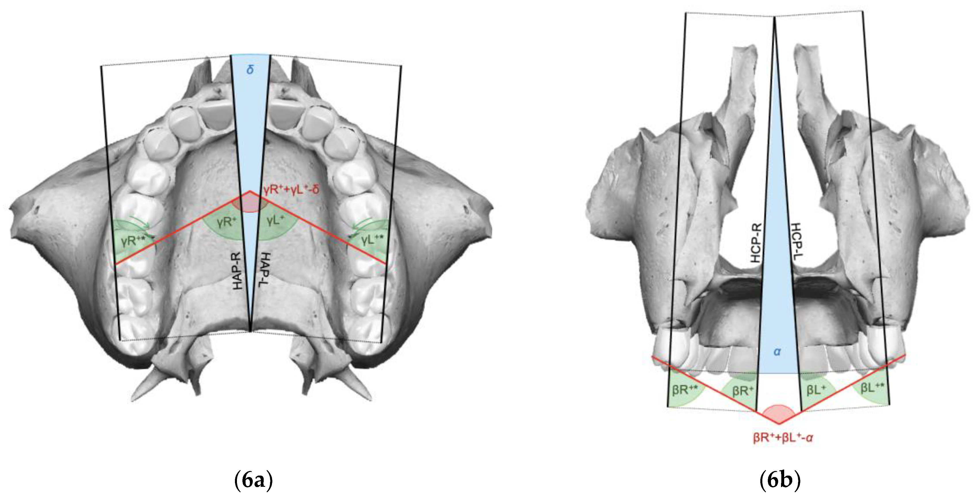
  • For clinical improvements to be achieved in the expansion phase, it is necessary that the molar rotation angle (γ) and the intermolar angle (β) at the end of expansion are less than the difference between the respective pre-treatment angle and the orthopedic expansion angle.
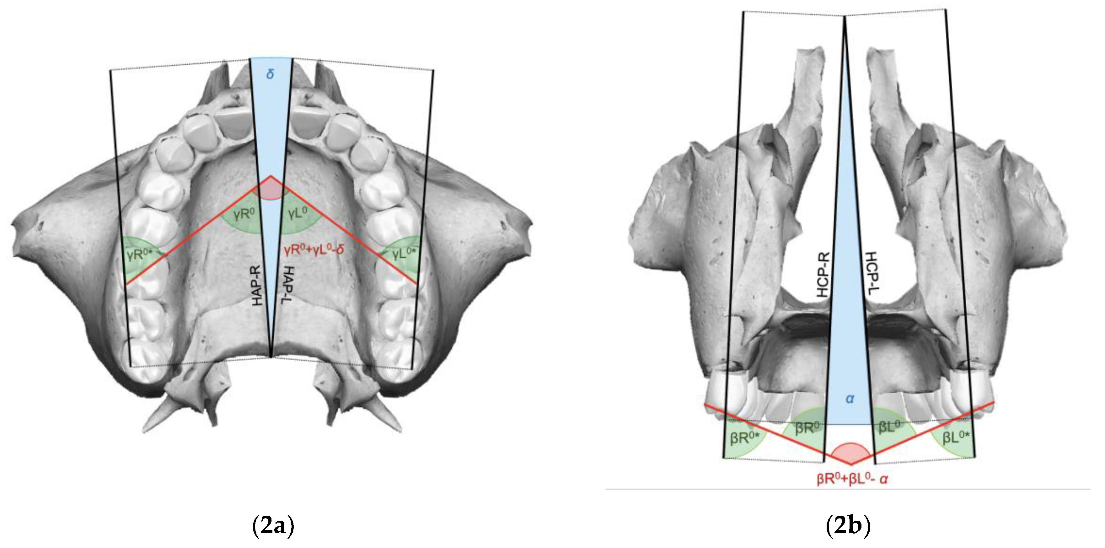
  • It is possible to calculate expansion angles (α and δ) by a reliable and reproducible method, respecting radiation protection principles, without requiring post-expansion CBCT scans, with the following formulas:
α = 2 · a r c t g A n s R i g h t - A n s L e f t / 2 A n s - N δ = 2 · a r c t g A n s R i g h t - A n s L e f t / 2 A n s - P n s
  • By offering a practical and minimally invasive approach for assessing RME outcomes, this study contributes to advancing safer and more effective orthodontic practices.

Author Contributions

Conceptualization, A.C.; methodology, M.S. and L.I.; software, M.S.; validation, A.C.; formal analysis, L.I.; investigation, L.I.; resources, L.I. and A.C.; data curation, M.S.; writing—original draft preparation, L.I.; writing—review and editing, M.S. and L.I.; visualization, M.S.; supervision, M.S. and A.C. All authors have read and agreed to the published version of the manuscript.

Funding

This research received no external funding.

Institutional Review Board Statement

Not applicable.

Informed Consent Statement

Informed consent was obtained from the subjects involved in the study.

Data Availability Statement

The original contributions presented in the study are included in the article, further inquiries can be directed to the corresponding author.

Conflicts of Interest

The authors declare no conflicts of interest.

References

  1. Angell, D.H. Treatment of irregularity of the permanent or adult teeth. Dent. Cosm. 1860, 1, 540–544. [Google Scholar]
  2. Haas, A.J. Palatal expansion: Just the beginning of dentofacial orthopedics. Am. J. Orthod. 1970, 57, 219–255. [Google Scholar] [CrossRef] [PubMed]
  3. Ugolini, A.; Cerruto, C.; Di Vece, L.; Ghislanzoni, L.H.; Sforza, C.; Doldo, T.; Silvestrini-Biavati, A.; Caprioglio, A. Dental arch response to Haas-type rapid maxillary expansion anchored to deciduous vs permanent molars: A multicentric randomized controlled trial. Angle Orthod. 2015, 85, 570–576. [Google Scholar] [CrossRef] [PubMed]
  4. Angelieri, F.; Cevidanes, L.H.; Franchi, L.; Gonçalves, J.R.; Benavides, E.; McNamara, J.A., Jr. Midpalatal suture maturation: Classification method for individual assessment before rapid maxillary expansion. Am. J. Orthod. Dentofac. Orthop. 2013, 144, 759–769. [Google Scholar] [CrossRef] [PubMed]
  5. Proffit, W.R.; Fields, H.W. Biomeccanica e meccanica. In Ortodonzia Moderna; Masson Publisher: Milano, Italy, 2001; pp. 313–382. [Google Scholar]
  6. Capozzi, F. (Ed.) Considerazioni sul significato clinico e biologico della disgiunzione rapida del palato. In La Disgiunzione Rapida del Palato in Ortognatodonzia; Piccin Nuova Libraia Publisher: Padova, Italy, 2008; pp. 1–52. [Google Scholar]
  7. Franchi, L.; Baccetti, T.; Lione, R.; Fanucci, E.; Cozza, P. Modifications of midpalatal sutural density induced by rapid maxillary expansion: A low-dose computed-tomography evaluation. Am. J. Orthod. Dentofac. Orthop. 2010, 137, 486–488. [Google Scholar] [CrossRef] [PubMed]
  8. Wertz, R.A. Skeletal and dental changes accompanying rapid midpalatal suture opening. Am. J. Orthod. 1970, 58, 41–66. [Google Scholar] [CrossRef] [PubMed]
  9. Liu, S.; Xu, T.; Zou, W. Effects of rapid maxillary expansion on the midpalatal suture: A systematic review. Eur. J. Orthod. 2015, 37, 651–655. [Google Scholar] [CrossRef] [PubMed]
  10. Sayar, G.; Kılınç, D.D. Rapid maxillary expansion outcomes according to midpalatal suture maturation levels. Prog. Orthod. 2019, 20, 27. [Google Scholar] [CrossRef] [PubMed]
  11. Podesser, B.; Williams, S.; Crismani, A.G.; Bantleon, H.P. Evaluation of the effects of rapid maxillary expansion in growing children using computer tomography scanning: A pilot study. Eur. J. Orthod. 2007, 29, 37–44. [Google Scholar] [CrossRef]
  12. McNamara, J.A., Jr.; Baccetti, T.; Franchi, L.; Herberger, T.A. Rapid maxillary expansion followed by fixed appliances: A long-term evaluation of changes in arch dimensions. Angle Orthod. 2003, 73, 344–353. [Google Scholar]
  13. De Baets, J. The role of the upper first molar in lower incisor crowding. J. Clin. Orthod. 1995, 29, 146–157. [Google Scholar] [PubMed]
  14. Ladner, P.T.; Muhl, Z.F. Changes concurrent with orthodontic treatment when maxillary expansion is a primary goal. Am. J. Orthod. Dentofac. Orthop. 1995, 108, 184–193. [Google Scholar] [CrossRef]
  15. Chung, C.H.; Font, B. Skeletal and dental changes in the sagittal, vertical, and transverse dimensions after rapid palatal expansion. Am. J. Orthod. Dentofac. Orthop. 2004, 126, 569–575. [Google Scholar] [CrossRef] [PubMed]
  16. Cerruto, C.; Ugolini, A.; Di Vece, L.; Doldo, T.; Caprioglio, A.; Silvestrini-Biavati, A. Cephalometric and dental arch changes to Haas-type rapid maxillary expander anchored to deciduous vs permanent molars: A multicenter, randomized controlled trial. J. Orofac. Orthop. 2017, 78, 385–393. [Google Scholar] [CrossRef]
  17. Ciambotti, C.; Ngan, P.; Durkee, M.; Kohli, K.; Kim, H. A comparison of dental and dentoalveolar changes between rapid palatal expansion and nickel-titanium palatal expansion appliances. Am. J. Orthod. Dentofac. Orthop. 2001, 119, 11–20. [Google Scholar] [CrossRef] [PubMed]
  18. Sandikçioğlu, M.; Hazar, S. Skeletal and dental changes after maxillary expansion in the mixed dentition. Am. J. Orthod. Dentofac. Orthop. 1997, 111, 321–327. [Google Scholar] [CrossRef] [PubMed]
  19. Pangrazio-Kulbersh, V.; Wine, P.; Haughey, M.; Pajtas, B.; Kaczynski, R. Cone beam computed tomography evaluation of changes in the naso-maxillary complex associated with two types of maxillary expanders. Angle Orthod. 2012, 82, 448–457. [Google Scholar] [CrossRef] [PubMed]
  20. Lombardo, L.; Albertini, E.; Arreghini, A.; D’Alessandro, A.; Siciliani, G. Rapid maxillary expansion on the permanent teeth versus the deciduous teeth: Comparison of skeletal and dentoalveolar effects by volumetric tomography. J. World Fed. Orthod. 2015, 4, 2–7. [Google Scholar]
  21. Kartalian, A.; Gohl, E.; Adamina, M.; Enciso, R. Cone-beam computer tomography evaluation of the maxillary dentoskeletal complex after rapid palatal expansion. Am. J. Orthod. Dentofac. Orthop. 2010, 138, 486–492. [Google Scholar] [CrossRef] [PubMed]
  22. Ok, U.P.D.; Kaya, T.U. Fractal Perspective on the Rapid Maxillary Expansion Treatment; Evaluation of the Relationship Between Midpalatal Suture Opening and Dental Effects. J. Stomatol. Oral Maxillofac. Surg. 2022, 123, 422–428. [Google Scholar] [CrossRef] [PubMed]
  23. Pereira, J.D.S.; Jacob, H.B.; Locks, A.; Brunetto, M.; Ribeiro, G.L.U. Evaluation of the rapid and slow maxillary expansion using cone-beam computed tomography: A randomized clinical trial. Dent. Press J. Orthod. 2017, 22, 61–68. [Google Scholar] [CrossRef] [PubMed]
  24. Christie, K.F.; Boucher, N.; Chung, C.H. Effects of bonded rapid palatal expansion on the transverse dimensions of the maxilla: A cone-beam computed tomography study. Am. J. Orthod. Dentofac. Orthop. 2010, 137, S79–S85. [Google Scholar] [CrossRef] [PubMed]
  25. Rosa, M.; Lucchi, P.; Manti, G.; Caprioglio, A. Rapid Palatal Expansion in the absence of posterior cross-bite to intercept maxillary incisor crowding in the mixed dentition: A CBCT evaluation of spontaneous changes of untouched permanent molars. Eur. J. Paediatr. Dent. 2016, 17, 286–294. [Google Scholar]
  26. Serafin, M.; Fastuca, R.; Zecca, P.A.; Lagravère, M.; Caprioglio, A. 3D occlusal changes of upper first molars after rapid maxillary expansion on permanent versus deciduous teeth: A retrospective multicenter CBCT study. Prog. Orthod. 2023, 24, 24. [Google Scholar] [CrossRef] [PubMed]
  27. Angle, E.H. Classification of malocclusion. Dent. Cosmos. 1899, 41, 248–264. [Google Scholar]
  28. Minich, C.M.; Araújo, E.A.; Behrents, R.G.; Buschang, P.H.; Tanaka, O.M.; Kim, K.B. Evaluation of skeletal and dental asymmetries in Angle Class II subdivision malocclusions with cone-beam computed tomography. Am. J. Orthod. Dentofac. Orthop. 2013, 144, 57–66. [Google Scholar] [CrossRef]
  29. Alavi, D.G.; BeGole, E.A.; Schneider, B.J. Facial and dental arch asymmetries in Class II subdivision malocclusion. Am. J. Orthod. Dentofac. Orthop. 1988, 93, 38–46. [Google Scholar] [CrossRef]
  30. Janson, G.R.; Metaxas, A.; Woodside, D.G.; de Freitas, M.R.; Pinzan, A. Three-dimensional evaluation of skeletal and dental asymmetries in Class II subdivision malocclusions. Am. J. Orthod. Dentofac. Orthop. 2001, 119, 406–418. [Google Scholar] [CrossRef] [PubMed]
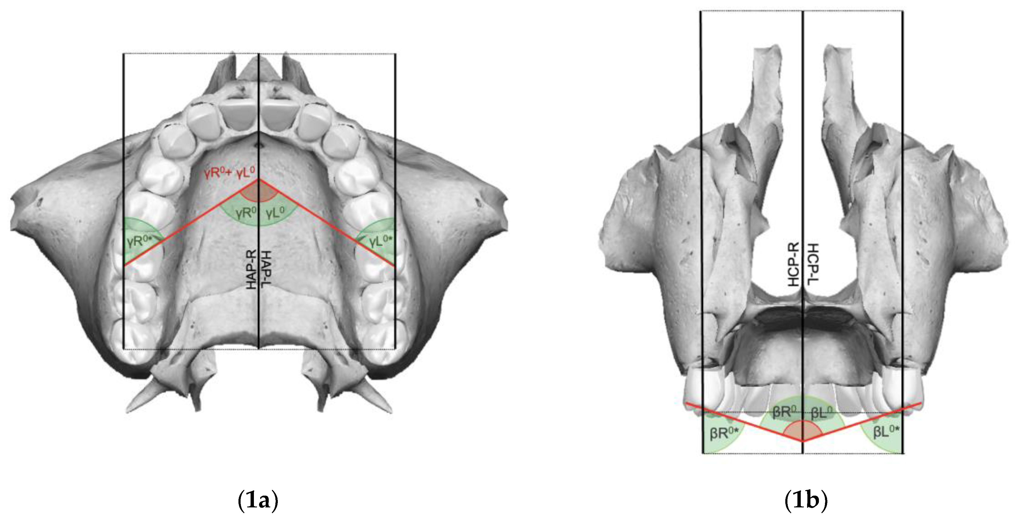
Figure 1. Pre-expansion case histories of the upper maxilla and palatine bones in occlusal (1a) and posterior (1b) views (δ = 0; γL0 = γR0 = γL0* = γR0*; γ0 = γR0 + γL0; α = 0; βL0 = βR0 = βL0* = βR0*; β0 = βR0 + βL0).
Applsci 14 11132 g001
Figure 2. Post-treatment result of orthopedic expansion of the mid-palatine suture in occlusal (2a) and posterior (2b) views without dental effects (γL0 = γR0 = γL0* = γR0* = γL’ = γR’ = γL’* = γR’*; γ’ = yR’ + yL’ − δ; βL0 = βR0 = βL0* = βR0* = βL’ = βR’ = βL’* = βR’*; β’ = βR’ + βL’ − α).
Applsci 14 11132 g002
Figure 3. Post-treatment result of orthopedic expansion of the mid-palatine suture in occlusal (3a) and posterior (3b) views with unilateral disto-rotation and buccal tipping (γL0 = γL0* = γL’ = γL’*; γR’ = γR’*; γ’ = yR’ + yL’ − δ; βL0 = βL0* = βL’ = βL’*; βR’ = βR’*; β’ = βR’ + βL’ − α).
Applsci 14 11132 g003
Figure 4. Post-treatment result of orthopedic expansion of the mid-palatine suture in occlusal (4a) and posterior (4b) views with bilateral disto-rotation and bilateral tipping (γL’ = γR’ = γL’* = γR’*; γ’ = yR’ + yL’ − δ; βL’ = βR’ = βL’* = βR’*; β’ = βR’ + βL’ − α).
Applsci 14 11132 g004
Figure 5. Post-treatment result of orthopedic expansion of the mid-palatine suture in occlusal views with asymmetrical mesio-rotation and disto-rotation (5a), and asymmetrical buccal and palatal tipping (5b) (γL’ = γL’*; γR’ = γR’*; γ’ = yR’ + yL’ − δ; βL’ = βL’*; βR’ = βR’*; β’ = βR’ + βL’ − α).
Applsci 14 11132 g005
Figure 6. Post-treatment result of orthopedic expansion of the mid-palatine suture in occlusal views with bilateral mesio-rotation (6a) and palatal tipping (6b) (γL’ = γL’* = γR’ = γR’*; γ’ = yR’ + yL’ − δ; βL’ = βL’* = βR’ = βR’*; β’ = βR’ + βL’ − α).
Applsci 14 11132 g006
Figure 7. Radiographic examinations on which measurements necessary to calculate orthopedic expansion angles can be conducted. Periapical radiograph at upper incisors level (7a), cone beam computed tomography (7b), latero-lateral projection teleradiography (7c).
Applsci 14 11132 g007
Figure 8. Intraoral scan of the upper arch of a clinical case with expander on miniscrews in anterior (superiorly) and occlusal (inferiorly) views showing upper permanent molar displacements at T0 (8a—displayed in green) and at T1 (8b—displayed in red); overlapping scan at both times (8c).
Applsci 14 11132 g008
Table 1. Three-dimensional landmarks’ position of analysis.
Landmarks
Anterior Nasal Spine (Ans)Most anterior point of the Ans (right and left)
Posterior Nasal Spine (Pns)Most posterior point of the Pns
Nasion (N)Most anterior point of the fronto-nasal suture
Mesio-Vestibular Cusp (MVC)Apex of the MV cusp of the upper first molar (right and left)
Mesio-Palatal Cusp (MPC)Apex of the MP cusp of the upper first molar (right and left)
Disto-Buccal Cusp (DBC)Apex of the DB cusp of the upper first molar (right and left)
Table 2. Three-dimensional reconstruction of analysis.
Planes
Hemi Sagittal Plane (HSP)Plane passing through the Ans (right and left), Pns, and N
Hemi Coronal Plane (HCP)Plane perpendicular to the HSP (right and left) and HAP, passing through the Pns
Hemi Axial Plane (HAP)Plane perpendicular to the HSP (right and left) and HCP, passing through the Pns
Table 3. Hemimaxillary and maxillary measurements of analysis.
Angles
Intermolar angle (β)Angle between the MVC and the MPC of the maxillary first molar line of the right and left sides
Right molar angle (βR)Angle generated by the intersection of the maxillary midline with the line joining the MVC and the MPC of the maxillary right first molar
Left molar angle (βL)Angle generated by the intersection of the maxillary midline with the line joining the MVC and the MPC of the maxillary left first molar
Molar angle of rotation (γ)Angle formed by the intersection of the lines passing over the tips of the MPC and the DBC of the right and left maxillary upper first molars
Right molar angle of rotation (γR)Angle formed by the intersection of the line passing over the MPC and the DBC tips of the right maxillary upper first molar and the Ans-Pns segment
Left molar angle of rotation (γL)Angle formed by the intersection of the line passing over the MPC and the DBC tips of the left maxillary upper first molar and the Ans-Pns segment
Orthopedic expansion angle on frontal view (α)Angle corresponding to the pyramid-like splaying pattern of the post-expansion maxillary components, projected on the frontal view
Orthopedic expansion angle on axial view (δ)Angle corresponding to the pyramid-like splaying pattern of the post-expansion maxillary components, projected on the axial view
Disclaimer/Publisher’s Note: The statements, opinions and data contained in all publications are solely those of the individual author(s) and contributor(s) and not of MDPI and/or the editor(s). MDPI and/or the editor(s) disclaim responsibility for any injury to people or property resulting from any ideas, methods, instructions or products referred to in the content.

