Development of a Cone Penetration Testing Apparatus with a Textured Shaft
Abstract
1. Introduction
2. Laboratory Experiments
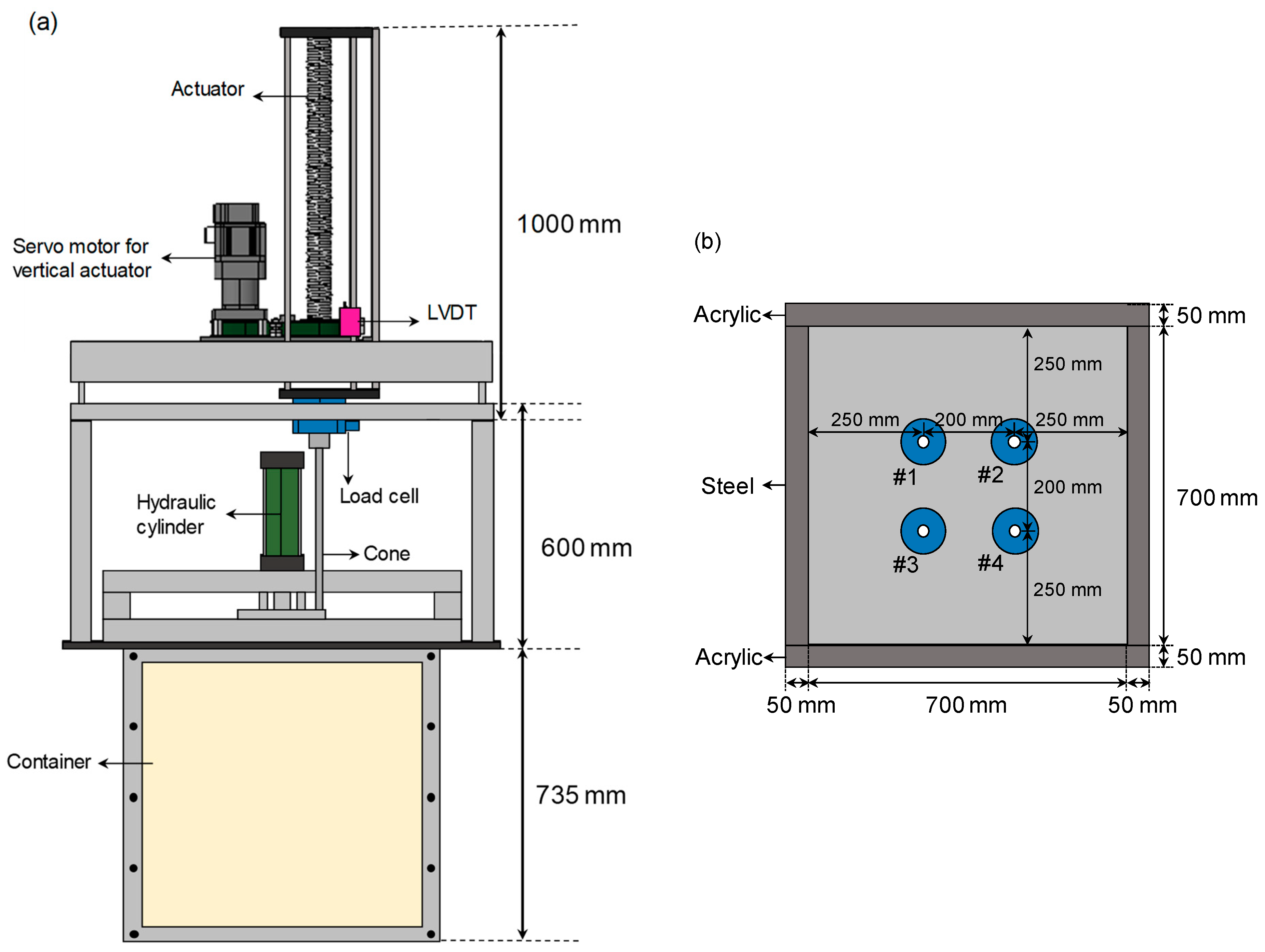
2.1. Cone Penetration Test Apparatus
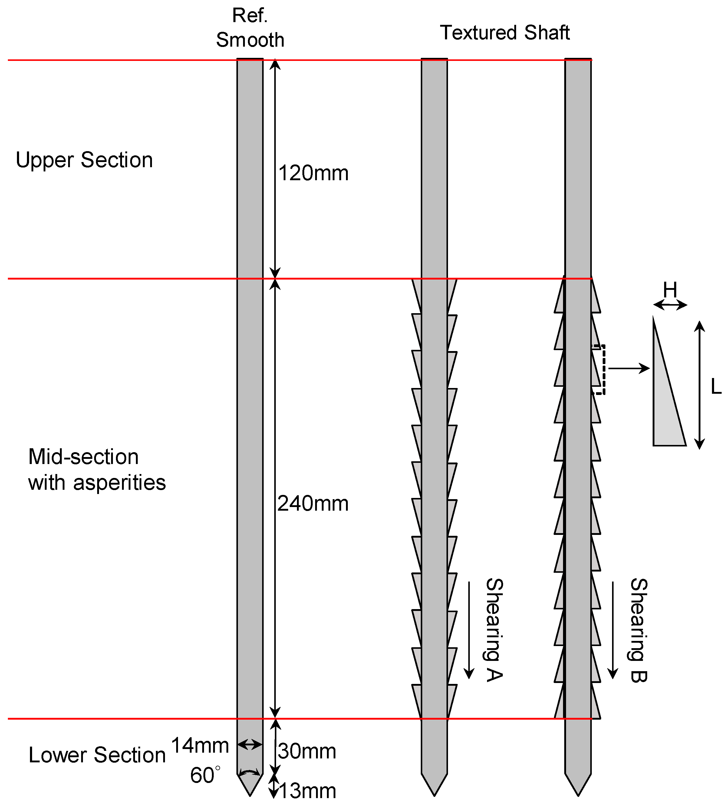
2.2. Manufacturing of Cones with Surface Asperities
2.3. Experimental Setup
- ①
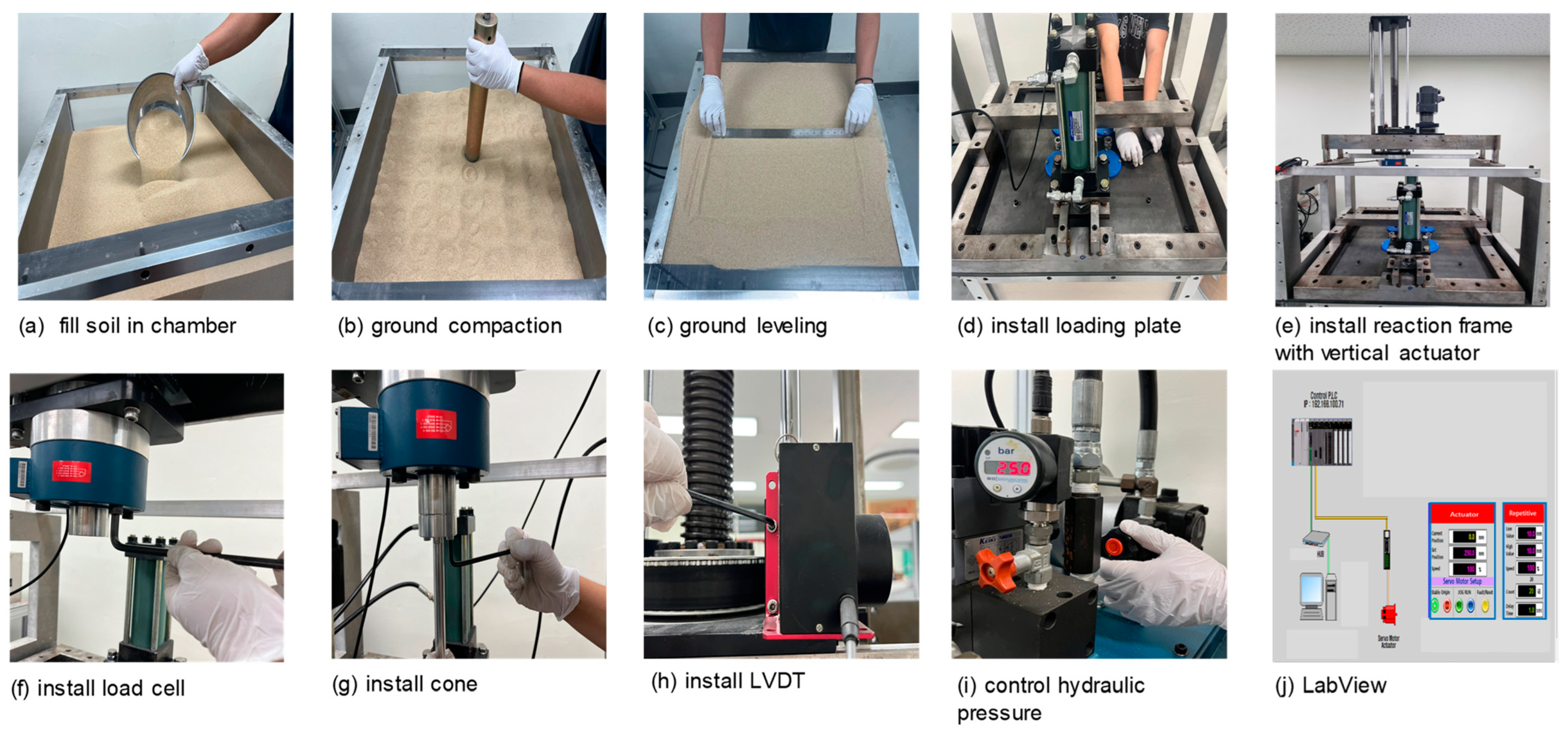
- Sand is placed to a depth of 100 mm using the air-pluviation method, followed by compaction using a 2.5 kg circular tamping rod dropped from a height of 350 mm. The sand is compacted in seven layers, each tamped 100 times. The surface is then leveled to ensure even contact between the sample surface and the bottom of the loading plate [Figure 3a–c].
- ②
- After securing the hydraulic cylinders to the loading plate, the plate is installed on top of the sand sample [Figure 3d].
- ③
- The vertical actuator for cone penetration and pull-out and the hollow load cell for vertical load measurement are attached to the reaction frame, which is secured to the model chamber using a bolt-nut system [Figure 3e,f].
- ④
- An aluminum connecting rod is installed in the center of the hollow load cell, and the upper part of cone is attached using bolts and nuts [Figure 3g]. A wire displacement sensor is installed to the bottom housing cover of the vertical actuator, and then the wire is connected to the upper housing cover [Figure 3h].
- ⑤
- The hydraulic cylinder control device is adjusted to apply a predetermined vertical load by opening the hydraulic cylinder pump [Figure 3i].
- ⑥
- Using the LabVIEW2021 program, the cone penetration depth and speed are controlled, and the load and vertical displacement are monitored in real-time during the test. The data are automatically saved after the experiment [Figure 3j].
3. Experimental Results and Analysis
3.1. Suitability of Model Chamber Size and the Distance Between Cones
3.2. Effect of Shaft Asperities and Load Direction on Cone Resistance
3.3. Change in Pull-Out Resistance After the Cone Penetration Test
4. Conclusions
- (a)
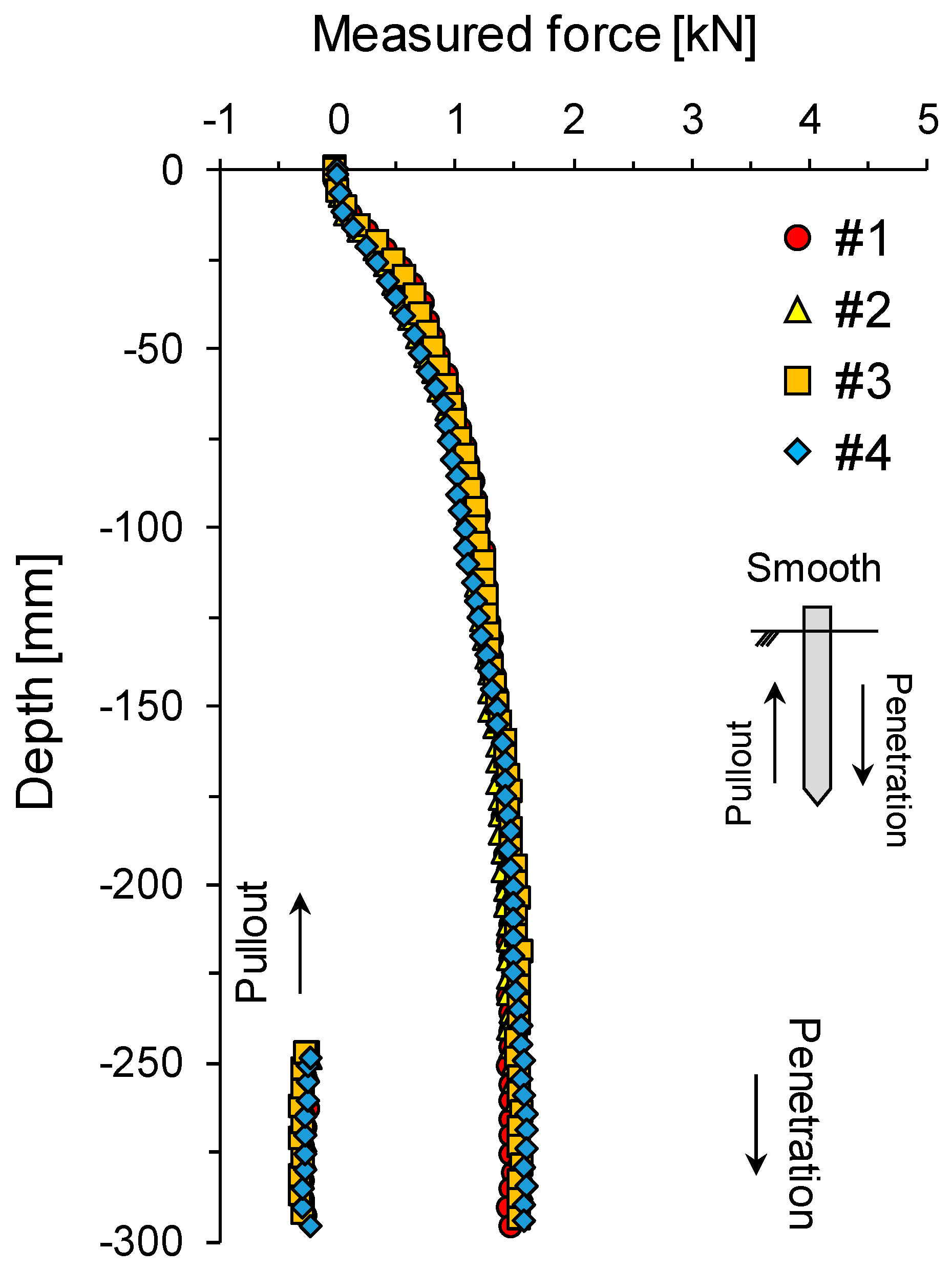
- Preliminary experiments are conducted using cones with smooth surfaces to quantitatively analyze the boundary effect related to model chamber size and the distance between the cones. Similar penetration resistance and pull-out resistance values are measured for cones penetrated at four different positions, confirming that the distance between the model chamber size and the cone developed in this study is sufficiently secured.
- (b)
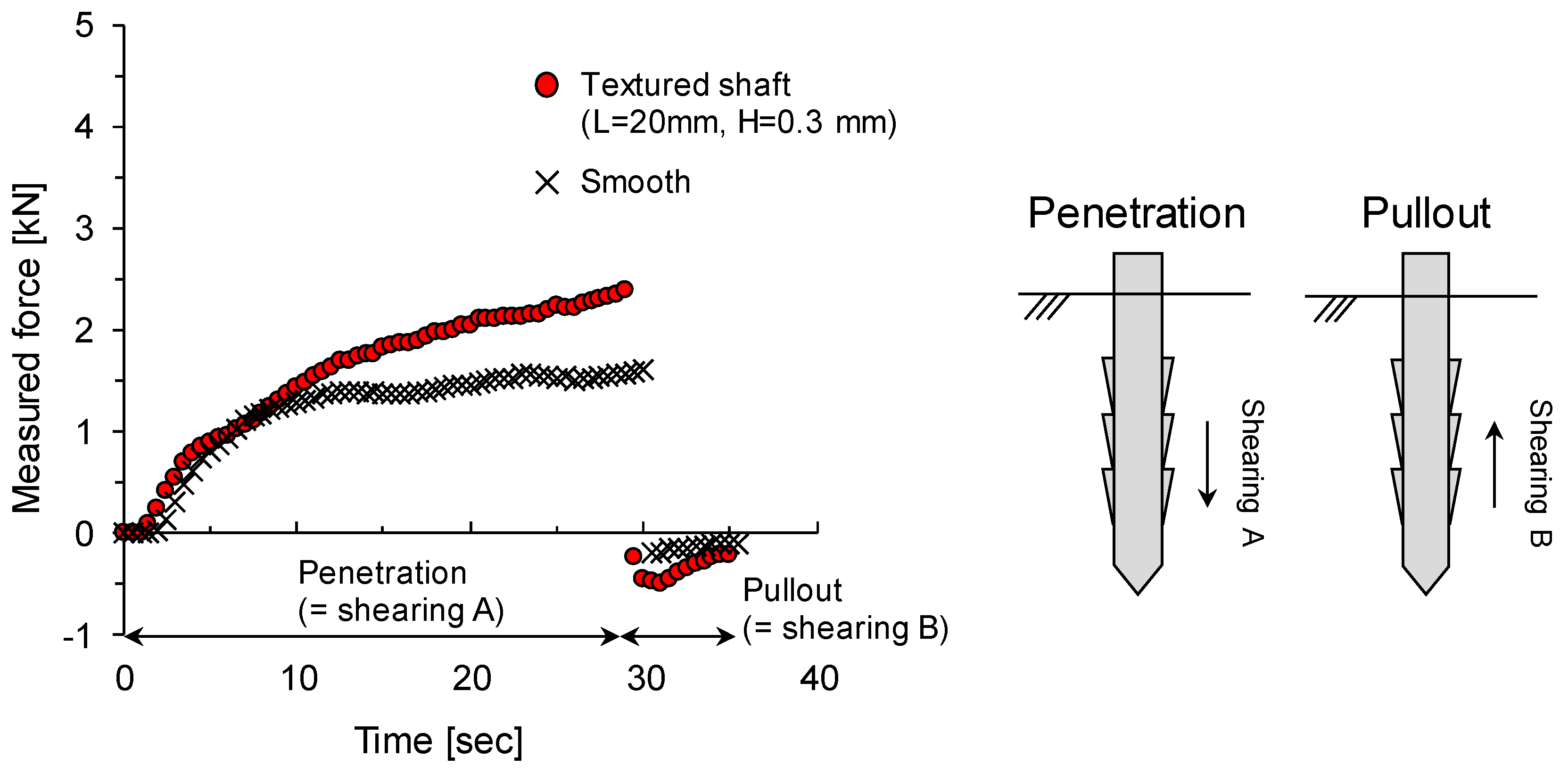
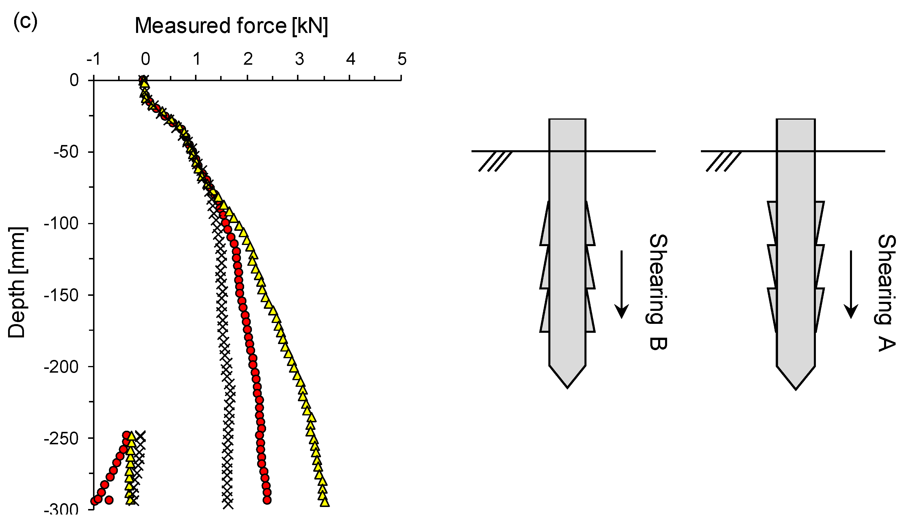
- A cone with surface asperity exhibits larger maximum penetration resistance than a smooth cone shaft, regardless of the load direction. During cone penetration, the shearing A direction condition produces a lower maximum penetration load compared to the shearing B direction condition. After the cone is penetrated, the pull-out resistance is dramatically changed with pull-out displacement in the shearing B direction condition, whereas the change in pull-out resistance is minimal in the shearing A direction condition.
- (c)
- Given scale geometry, a higher scale height or shorter scale length mobilizes greater penetration and pull-out resistance. In particular, the change in shear resistance according to the geometry scale is significantly affected by scale length rather than scale height. A higher height of asperity or shorter length of asperity indicates a rough surface that individual soil deformation wedges. Meanwhile, shorter height or longer length of asperity produces more uniform shear bands along the asperities.
Author Contributions
Funding
Institutional Review Board Statement
Informed Consent Statement
Data Availability Statement
Conflicts of Interest
References
- Sun, T.; Wang, C.; Xu, D.; Lin, Z.; Yang, J.; Liu, S.; Yang, F. Effect of Solidified Depth on the Vertical Compressive Bearing Characteristics of the Soil Continuously Solidified Pile Group Foundation. Appl. Sci. 2023, 13, 12850. [Google Scholar] [CrossRef]
- Wang, Z.; Jiang, J.; Wang, S.; Fu, C.; Yang, D. Analysis on Bearing Behavior of Single Pile under Combined Action of Vertical Load and Torque in Expansive Soil. Appl. Sci. 2023, 13, 4133. [Google Scholar] [CrossRef]
- Lu, Y.; Li, D.; Jia, S.; Wang, K. A new method for evaluating the bearing capacity of the bridge pile socketed in the soft rock. Appl. Sci. 2021, 11, 5923. [Google Scholar] [CrossRef]
- Elsawy, M.B.; Alsharekh, M.F.; Shaban, M. Modeling undrained shear strength of sensitive alluvial soft clay using machine learning approach. Appl. Sci. 2022, 12, 10177. [Google Scholar] [CrossRef]
- Ali, O.K.; Abbas, H.O. Performance assessment of screw piles embedded in soft clay. Civ. Eng. J. 2019, 5, 1788–1798. [Google Scholar] [CrossRef]
- Kim, D.; Jeong, S. Applicability of bearing capacity for single drilled shaft using empirical equation based on ground condition. J. Korean Geosynth. Soc. 2019, 18, 167–180. [Google Scholar] [CrossRef]
- Lee, J.H.; Lee, K.; Kim, D. Analysis of axial capacity and constructability of helical pile with inner cone penetration. J. Korean Geosynth. Soc. 2017, 16, 1–11. [Google Scholar]
- Bak, J.; Lee, K.; Choi, B.H.; Kim, D. Numerical analysis of helical pile behavior varying number and diameter of helices. KSCE J. Civ. Environ. Eng. Res. 2019, 39, 211–217. [Google Scholar]
- Elsherbiny, Z.H.; El Naggar, M.H. Axial compressive capacity of helical piles from field tests and numerical study. Can. Geotech. J. 2013, 50, 1191–1203. [Google Scholar] [CrossRef]
- Han, J.T.; Kim, S.R.; Jang, Y.E.; Lee, S.H. Evaluation of bearing capacity of waveform micropile by numerical analyses. J. Korea Acad. Ind. Coop. Soc. 2013, 14, 5906–5914. [Google Scholar]
- Jang, Y.E.; Han, J.T.; Kim, J.H.; Park, H.J.; Kim, S.H. Evaluation of axial bearing capacity of waveform micropile by centrifuge test. J. Korean Geotech. Soc. 2015, 31, 39–49. [Google Scholar] [CrossRef][Green Version]
- Baek, S.-H.; Han, J.T.; Kim, S.J.; Kim, J. Evaluation of the effect of waveform micropiles on reinforcement of foundation structures through field load tests. J. Korean Geotech. Soc. 2023, 39, 29–40. [Google Scholar]
- Martinez, A.; Palumbo, S.; Todd, B.D. Bioinspiration for anisotropic load transfer at soil–structure interfaces. J. Geotech. Geoenviron. Eng. 2019, 145, 04019074. [Google Scholar] [CrossRef]
- O’Hara, K.B.; Martinez, A. Effects of asperity height on monotonic and cyclic interface behavior of bioinspired surfaces under constant normal stiffness conditions. In Geo-Congress 2020; American Society of Civil Engineers: Reston, VA, USA, 2020. [Google Scholar]
- Lee, S.-H.; Chong, S.-H. A study on friction anisotropy between sand and surface asperities of plate using modified direct shear test. J. Korean Geotech. Soc. 2022, 38, 29–38. [Google Scholar]
- Nawaz, M.N.; Lee, S.H.; Chong, S.H.; Kim, J.H. Modification of direct shear apparatus for soil-soil and soil-solid interface testing. Geomech. Eng. 2023, 35, 325–332. [Google Scholar]
- Lee, S.-H.; Nawaz, M.N.; Chong, S.-H. Estimation of interface frictional anisotropy between sand and snakeskin-inspired surfaces. Sci. Rep. 2023, 13, 3975. [Google Scholar] [CrossRef] [PubMed]
- Nawaz, M.N.; Lee, S.H.; Chong, S.-H.; Ku, T. Interface frictional anisotropy of dilative sand. Sci. Rep. 2024, 14, 6166. [Google Scholar] [CrossRef] [PubMed]
- O’Hara, K.B.; Martinez, A. Monotonic and cyclic frictional resistance directionality in snakeskin-inspired surfaces and piles. J. Geotech. Geoenviron. Eng. 2020, 146, 04020116. [Google Scholar] [CrossRef]
- O’Hara, K.B.; Martinez, A. Cyclic axial response and stability of snakeskin-inspired piles in sand. Acta Geotech. 2024, 19, 1139–1158. [Google Scholar] [CrossRef]
- Bolton, M.D.; Gui, M.W.; Gamier, J.; Corte, J.F.; Bagge, G.; Laue, J.; Renzi, R. Centrifuge cone penetration tests in sand. Géotechnique 1999, 49, 543–552. [Google Scholar] [CrossRef]



| Properties | Value |
|---|---|
| Specific gravity GS [-] | 2.62 |
| Maximum void ratio emax [-] | 0.92 |
| Minimum void ratio emin [-] | 0.62 |
| Average particle size D50 [mm] | 0.58 |
| Coefficient of curvature Cc [-] | 0.93 |
| Uniformity coefficient Cu [-] | 1.46 |
| Penetration Direction | Geometry of Scale [mm] | Scale Ratio L/H [-] | Measured Force [kN] | ||
|---|---|---|---|---|---|
| Length L | Height H | Penetration | Pull-Out | ||
| Shearing A | 20 | 0.3 | 66.67 | 1.95 | −0.33 |
| Shearing B | 20 | 0.3 | 66.67 | 2.10 | −0.22 |
| Shearing A | 20 | 0.5 | 40 | 1.97 | −0.52 |
| Shearing B | 20 | 0.5 | 40 | 2.38 | −0.18 |
| Shearing A | 6 | 0.3 | 20 | 2.11 | −0.64 |
| Shearing B | 6 | 0.3 | 20 | 2.79 | −0.27 |
| Smooth | - | - | - | 1.51 | −0.13 |
Disclaimer/Publisher’s Note: The statements, opinions and data contained in all publications are solely those of the individual author(s) and contributor(s) and not of MDPI and/or the editor(s). MDPI and/or the editor(s) disclaim responsibility for any injury to people or property resulting from any ideas, methods, instructions or products referred to in the content. |
© 2024 by the authors. Licensee MDPI, Basel, Switzerland. This article is an open access article distributed under the terms and conditions of the Creative Commons Attribution (CC BY) license (https://creativecommons.org/licenses/by/4.0/).
Share and Cite
Kim, T.-Y.; Jung, K.-H.; Chong, S.-H. Development of a Cone Penetration Testing Apparatus with a Textured Shaft. Appl. Sci. 2024, 14, 10090. https://doi.org/10.3390/app142210090
Kim T-Y, Jung K-H, Chong S-H. Development of a Cone Penetration Testing Apparatus with a Textured Shaft. Applied Sciences. 2024; 14(22):10090. https://doi.org/10.3390/app142210090
Chicago/Turabian StyleKim, Tae-Young, Kyung-Hoon Jung, and Song-Hun Chong. 2024. "Development of a Cone Penetration Testing Apparatus with a Textured Shaft" Applied Sciences 14, no. 22: 10090. https://doi.org/10.3390/app142210090
APA StyleKim, T.-Y., Jung, K.-H., & Chong, S.-H. (2024). Development of a Cone Penetration Testing Apparatus with a Textured Shaft. Applied Sciences, 14(22), 10090. https://doi.org/10.3390/app142210090


