Abstract
In this study, the effects of laser power on the microstructure and mechanical properties of Inconel 718 formed by SLM were systematically studied. The results show that with the increase in laser power from 285 W to 360 W, the increase in working temperature in the molten pool promoted the evaporation of gas and the vaporization of the low-melting-point alloy components, and the relative density gradually increased from 99.31% to 99.79%. In addition, with the increase in laser energy density, the microstructure gradually coarsened from columnar dendrites to cellular crystals. The nano-hardness of the material decreased with the increase in laser power. The nano-hardness of four groups of samples from 285 W to 360 W decreased form 3.43 GPa to 2.09 GPa, and the elastic modulus decreased form 205.72 GPa to 199.91 GPa.
1. Introduction
As one of the more mature additive manufacturing technologies in recent years, the selective laser melting (SLM) technology has been increasingly applied in the field of industrial manufacturing. Complex metal parts can be directly manufactured by the SLM technology based on CAD data by selectively melting consecutive metal powder layers [1,2]. The main advantage of the SLM technology is the ability to manufacture almost completely dense metal parts (even over 99.9%), without post-processing such as infiltration, sintering, or HIP. Additionally, the SLM technology has unique advantages in the forming and manufacturing of complex geometric structures. Consequently, it has significant advantages and development prospects in fields such as the aerospace, automotive, and medical industries [3,4]. As one of the metal materials formed by the SLM technology, nickel-based high-temperature alloys have been widely used in the aerospace field for components.
Among nickel-based alloys, Inconel 625 and Inconel 718 have superior thermal–mechanical properties compared to other nickel-based alloys [5]. Inconel 718 is a precipitation hardening superalloy with Nb and Mo as the main strengthening elements, and its three main elements are Ni, Cr, and Fe [6,7]. It has good comprehensive mechanical properties at high temperatures (approximately 700 °C) [8,9]. Therefore, it has been widely used in the manufacturing of high-temperature components such as turbine blades, rocket engines, etc. [10] in the industrial manufacturing field. Research has shown that Inconel 718 alloy parts formed by SLM have a dense and fine structure, surpassing those of Inconel 718 alloy materials processed by traditional processes in multiple aspects [11].
During the process of forming Inconel 718 alloy material by SLM, the quality and performance of the formed parts can be significantly impacted by various process parameters such as scanning path, layer thickness, laser power, etc. Many scholars have studied the forming of Inconel 718 based on these process parameters. Park et al. [12] investigated the reduction in residual stress and the correlation between microstructure and mechanical properties of Inconel 718 alloy during the SLM process through low-energy-density rescan heating. Liu et al. [13] studied the effect of the laser scanning speed on the density of Inconel 718 alloy formed by SLM. Zheng et al. [14] studied the effect of laser scanning spacing on the density, phase composition, grain morphology, and orientation relationship of Inconel 718 alloy formed by SLM. Wei et al. [15] studied the effect of scanning measurement on the forming quality of Inconel 718 samples formed by SLM. Xu et al. [16] studied the effect of energy density on the upper surface roughness and density of SLM-formed specimens [17]. The microstructure and mechanical properties of SLM-formed parts can be directly impacted by laser power, which is an important process parameter for measuring laser energy [18].
Currently, there is relatively little research on the effect of laser power on the quality of Inconel 718 alloy formed by SLM. Many scholars have studied the shaping of laser power in other related materials. For examples, the density and hardness of SLMed GH4169 alloy increased with the increase in laser power [19]. Two leading causes of pore formation in Inconel 738LC were determined as lack of fusion and keyholes, which were attributed to different energy input densities [20]. IN 625 is sensitive to the processing parameters, and excessively high and low scan speeds may result in lack of fusion and unstable melt pools, respectively, and then cause the formation of large pores. Therefore, choosing the suitable values for laser power and scan speed can lead to samples with relative densities exceeding 99.8% [21]. The hardness and density of SLMed Ti-6Al-4V are highly related to the formation of a melting pool and porosity during the process [22]. The laser power is the main parameter that controls the transference of energy from the SLM system to the process powder, aiming at its melting in a controlled and homogeneous fashion to produce dense bulk components [23].
This study designed an Inconel 718 sample printing scheme by changing the laser power and systematically studied the influence of laser power on the density, microstructure, and mechanical properties of the samples. The evolution of densification, microstructure, and mechanical properties of Inconel 718 during SLM forming under different laser powers was explored by analyzing the mechanism of dendrite growth in the molten pool. This study provides a theoretical reference for subsequent research on the SLM forming of Inconel 718 alloy.
2. Sample Preparation and Experimental Methods
2.1. Materials and Powder
The powder of Inconel 718 was made by the aerosol method, and the morphology of the Inconel 718 powder is shown in Figure 1a. The powder particles were mostly spherical in shape, and very small satellite particles were attached to the main particles. The particle size distribution of Inconel 718 powder was detected by a Mastersizer-v 3.50 laser particle size analyzer, and the measured Inconel 718 powder is shown in Figure 1b; the average particle size was 17.8 μm. The chemical elements of the powder were measured by an Olympus spectrometer. The chemical element composition of the Inconel 718 powder used in this experiment is shown in Table 1.
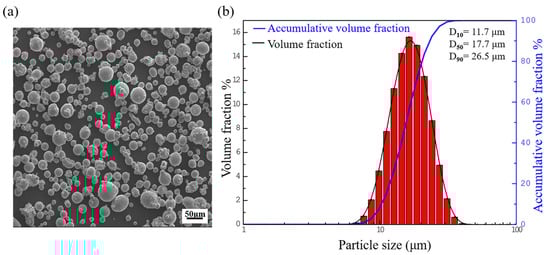
Figure 1.
Inconel 718 alloy powder: (a) SEM image of the original powder morphology, (b) powder particle size distribution.

Table 1.
Measured chemical composition of the as-received Inconel 718 powder in wt.%.
2.2. Sample Preparation
This experiment on laser power was mainly divided into sample manufacturing, sample processing, and observation. By designing a single-factor experiment and changing the laser power P, Inconel 718 samples were formed using SLM, with each block sample size of 8 mm × 8 mm × 8 mm. The processing conditions of samples were scanning distance of 0.11 mm and spreading thickness of 0.04 mm. The specific design parameters are shown in Table 2 (φ = P/ν, where P is the laser power, and ν is the scanning speed).
Table 2.
Processing parameters of different laser powers.
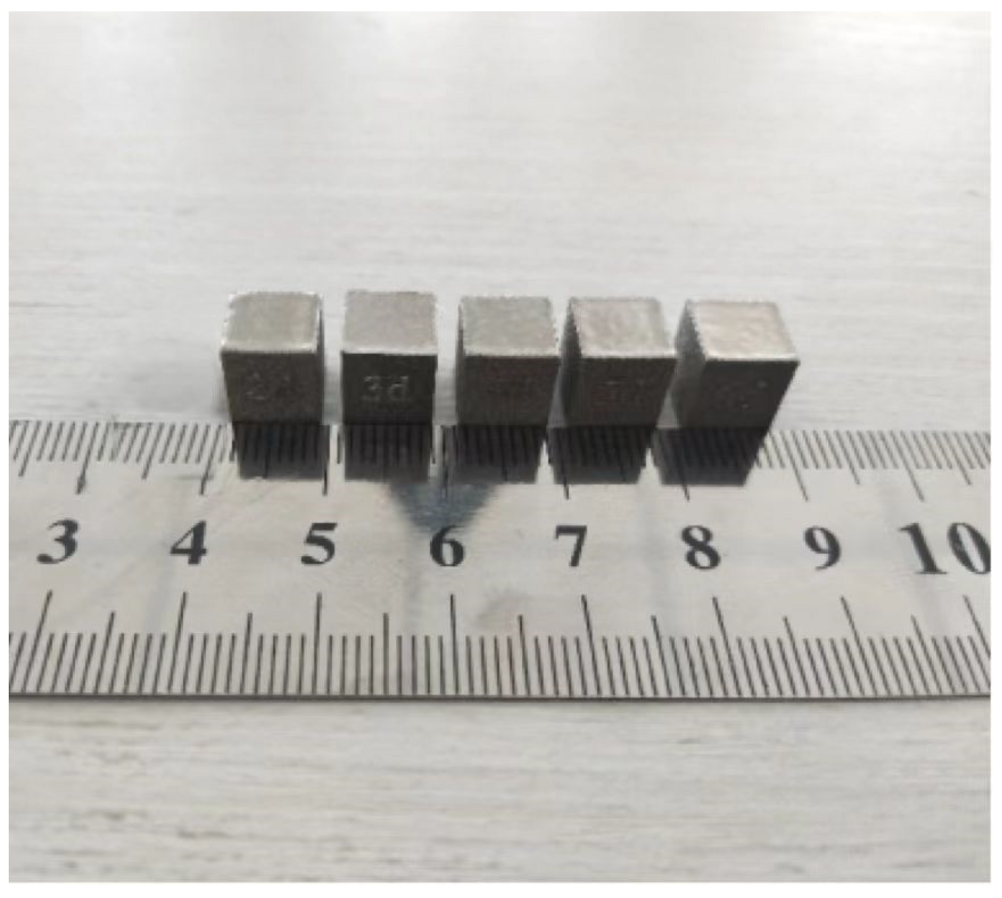
A linear grating shape-scanning strategy was adopted in the experiment, with a laser scanning angle of 67° between each layer. The forming equipment used was the M290 selective laser melting equipment produced by German EOS (Hamburg, Germany), and the formed samples are shown in Figure 2.
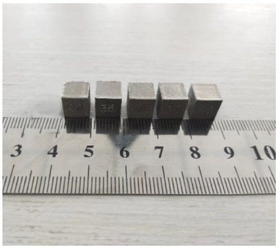
Figure 2.
SLM-formed Inconel 718 block specimens under different laser power values.
2.3. Experimental Methods
After the sample preparation was completed, the sample was cross-sectioned and polished, and porosity and defects were observed and analyzed by optical microscopy.
In order to study the evolution of the microstructure of Inconel 718 samples formed by SLM under different process conditions and analyze the fracture failure mechanism at room temperature, the samples were prepared according to the metallographic experimental sample preparation procedure. In addition, the samples were corroded by the chemical erosion method by aqua Regis (HCL:HNO3 = 3:1). The etching time was about 5 s. The prepared samples were characterized by scanning electron microscopy (SEM, Phenom ProX, Thermo Fisher Scientific, Norristown, PA, USA), scanning electron microscopy with an Edax electron backscatter diffraction (EBSD, Tescan Vga3, TESCAN, Brno, Czech Republic) system, and X-ray diffraction (XRD, Bruker D8 Advance, Bruker AXS, Karlsruhe, Germany). After polishing, each experimental sample was observed using an X-ray diffractometer to analyze the changes in peak intensity and corresponding diffraction angle. The test anode Cu target had a wavelength of 1.54056 and a high scanning speed of 4°/min for a wide range of scanning. Small-angle scanning was slow, with a scanning speed of 1°/min and a step size of 0.02°.
The mechanical properties, hardness, and elastic modulus of the specimens were analyzed. By using a nanoindenter to test the samples and analyzing the displacement–load curves of the material, mechanical performance indicators such as nano-hardness and elastic modulus of the material could be obtained.
3. Experiment and Result Analysis
3.1. Phase Analysis
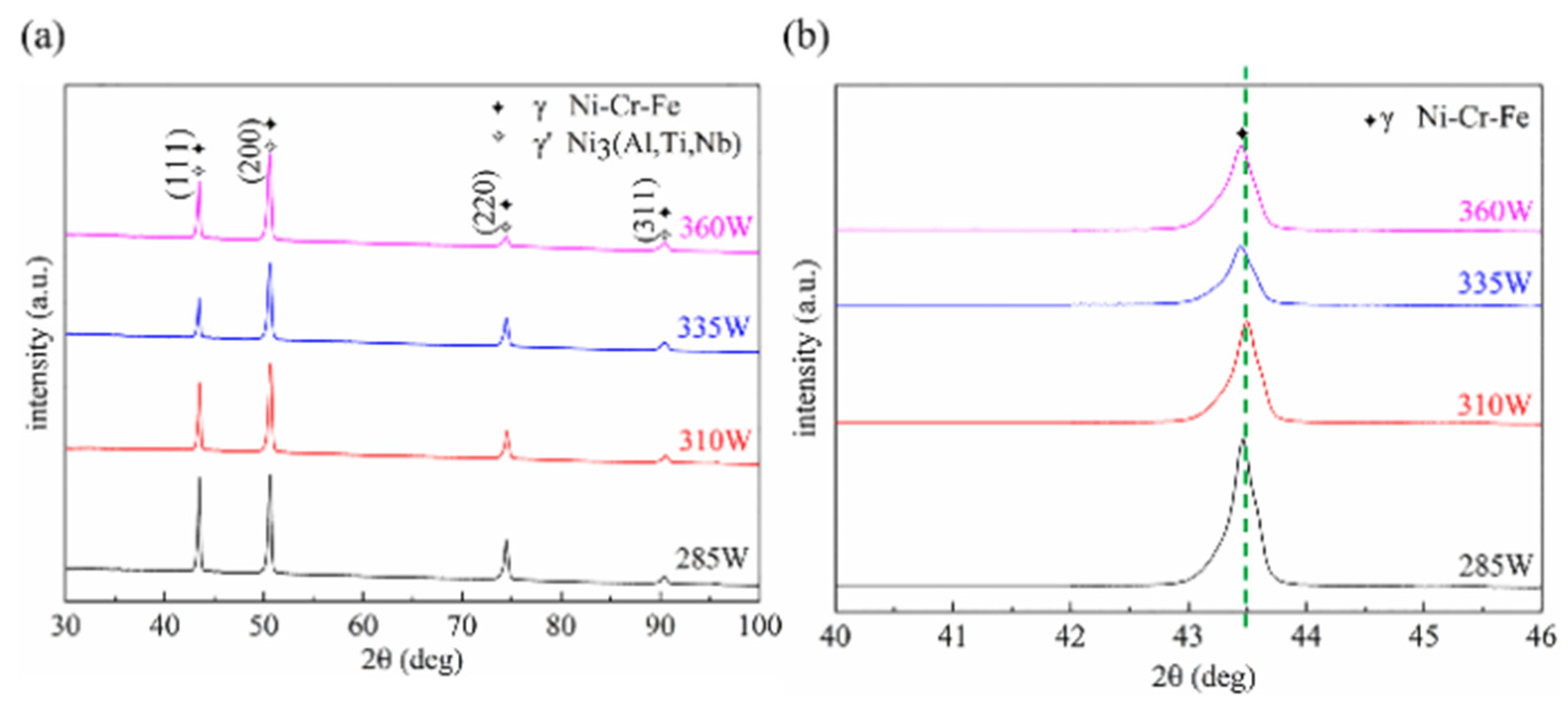
The XRD patterns of the samples formed by SLM under different laser powers are shown in Figure 3. Figure 3a shows the scanning results over a large angle range. It can be seen from the figure that the Inconel 718 alloy formed by SLM has a face-centered cubic austenite phase comprising Ni, Cr, and Fe, and a precipitation strengthening γ′ phase consisting of Ni3 (Al, Ti). The diffraction peak intensity of the γ′ phase is proportional to its volume fraction, and any peak broadening is primarily the result of an increased dislocation density [24]. Since the γ′ phase and the matrix γ coincided within a large angle range, further XRD testing was conducted on γ within a small angle range of 2θ = 40–46°, and the results are shown in Figure 3b. The values of the main diffraction angle, diffraction intensity, and half-peak width are shown in Table 3. It can be observed that the peak intensity gradually weakened as the laser power gradually increased from 285 W to 335 W. Such feature indicates that with the increase in laser power, auxiliary strengthening phases such as γ′ precipitated in the matrix. From Figure 3b and Table 3, it can be seen that as the laser power increased from 310 W to 360 W, the diffraction angle at the diffraction peak gradually decreased, and the diffraction peak gradually shifted to the left. In accordance with the Bragg diffraction equation, the spacing between crystal planes increased. No other phases were detected via XRD.
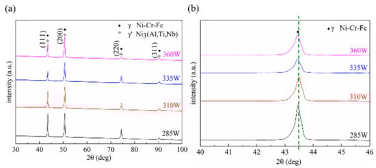
Figure 3.
XRD patterns of the XY plane of Inconel 718 samples formed by SLM under different laser powers: (a) scan within a large angle range 2θ = 30–100°; (b) small-angle scanning, 2θ = 40–46°.
Table 3.
The 2θ values of the main peak, diffraction peak intensity, and half-peak width in the XRD spectra and the average thickness of the grain perpendicular to the crystal plane.
In the Bragg diffraction equation Formula (1), d is the crystal plane spacing; θ is the diffraction angle; n is the diffraction order; and λ is the wavelength of the X-rays. The decrease in 2θ indicates an increase in the spacing between crystal planes during angular reduction. This suggests that during the SLM forming process, lattice distortion occurred due to the thermal stress generated by the rapid laser heating and cooling. Thermal accumulation in the molten pool is equivalent to preheating the produced parts and conducting an annealing heat treatment, which can reduce the residual stress and change the crystal lattice parameters [25].
2dsinθ = nλ
In accordance with Table 3, as the laser power increased from 285 W to 360 W, the half peak width first increased and then decreased. In accordance with Scheler’s Formula (2), the value of Dc could be obtained as the laser power increased from 285 W to 360 W, as shown in Table 3. Dc is the average thickness of the grain perpendicular to the grain plane direction; λ is the wavelength of the X-rays; B is the half peak width of the X-ray diffraction peak; and θ is the X-ray diffraction angle. The grain size decreased with the increase in half-peak width. It means that under the experimental conditions, the grain size underwent a fluctuation process, first decreasing and then increasing.
3.2. Analysis of Density and Molten Pool Morphology
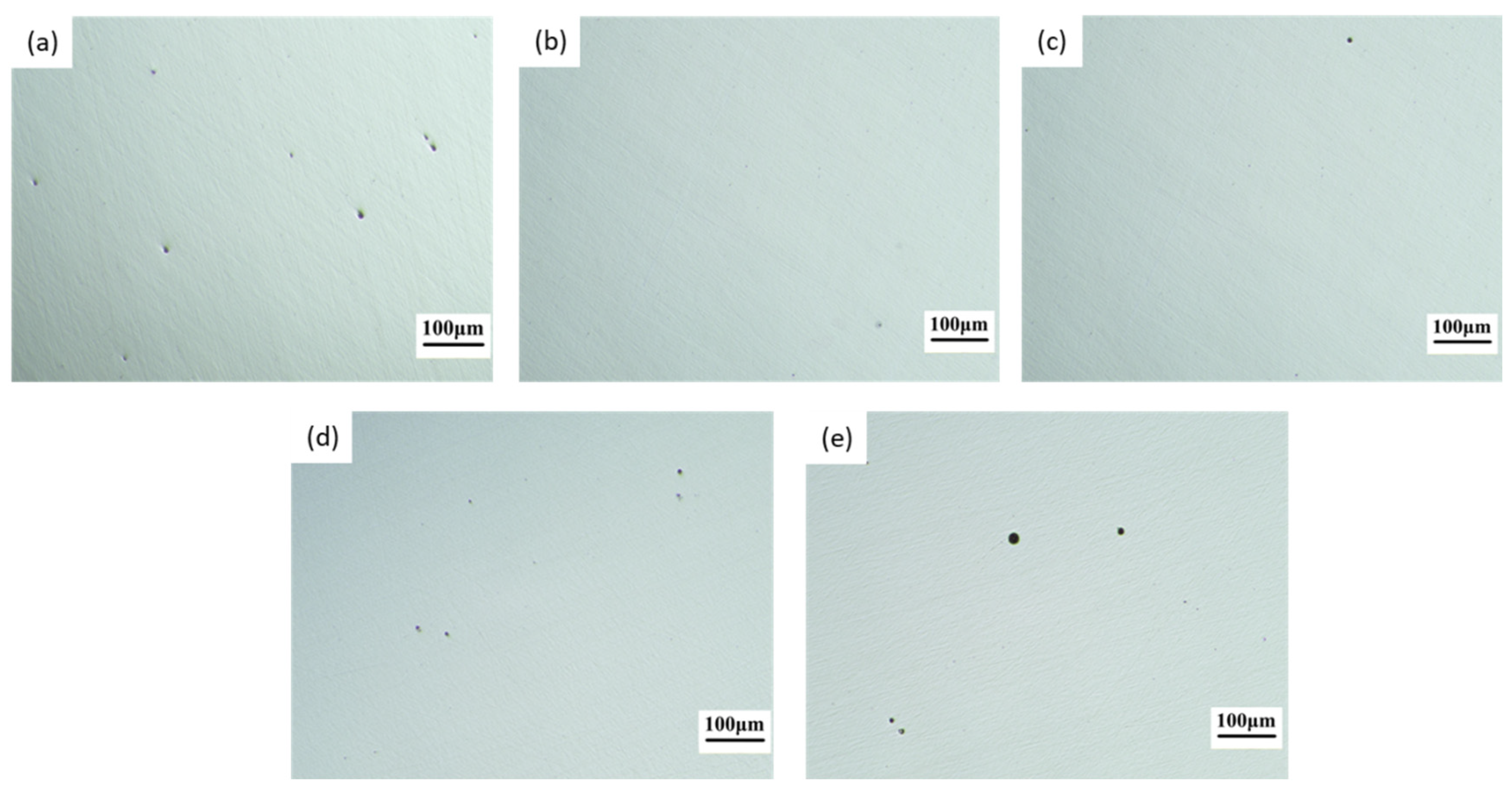
The variation in the density of the Inconel 718 samples formed by SLM with laser power is shown in Table 4. When the laser power increased from 260 W to 360 W, the density remained above 99%. It showed a trend of first increasing and then gradually decreasing. When the laser power was at a minimum of 260 W, the relative density was 99.31%. It can be seen that there are many smaller pores in Figure 4. When the laser power increased from 285 W to 360 W, the relative density gradually decreased.
Table 4.
Relative density of Inconel 718 samples formed by SLM under different laser powers.
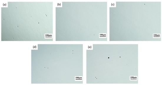
Figure 4.
Optical microscope images of Inconel 718 samples formed by SLM under different laser powers: (a) P = 260 W, (b) P = 285 W, (c) P = 310 W, (d) P = 335 W, (e) P = 360 W.
When the laser power was set at 260 W, the low laser energy density resulted in a low working temperature within the molten pool. Therefore, powder melting was insufficient. This led to an incomplete filling of the molten pool that decreased the overlap rate. As a result, many pores were present on the surface of the sample. As the laser power gradually increased to 285 W, the laser energy density slightly increased, and the Marangoni effect within the molten pool promoted the rheological properties of the molten pool, thereby increasing the density. When the laser power increased from 285 W to 360 W, the laser energy density further increased. The increase in working temperature in the molten pool promotes the evaporation of gases and the vaporization of low-melting-point alloys. Therefore, the relative density gradually decreases.
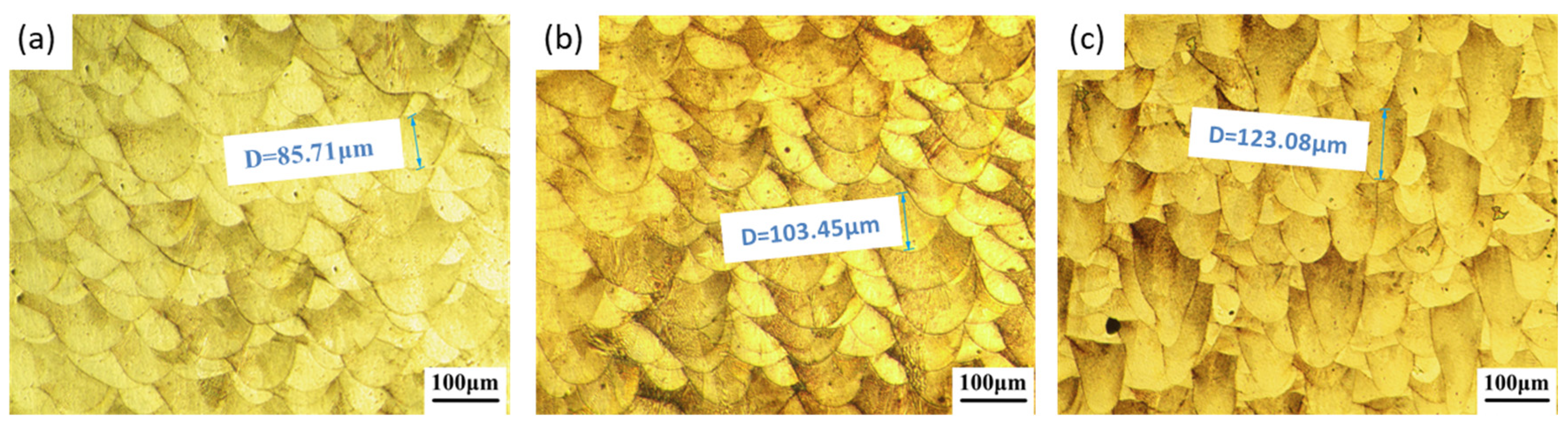
The morphology of the molten pool perpendicular to the forming direction of the Inconel 718 sample formed by SLM is shown in Figure 5. The width and depth of different molten pools in Figure 4a,b are uneven, which was mainly due to the rapid heating and cooling in the SLM forming process. In this process, the molten material is cooled and solidified layer by layer. Therefore, during the cooling process of each laser-irradiated molten material, each layer is affected by the adjacent cladding layer and the previous solidification layer. When the laser power was 310 W, the depth of the molten pool was approximately 85.71 ± 10 μm. When the laser power was 335 W, the depth of the molten pool was approximately 103.45 ± 10 μm. When the laser power was 360 W, the depth of the molten pool was approximately 123.08 ± 10 μm (Figure 5). As the laser power increased, the depth of the molten pool gradually increased. The shape of the molten pool is determined by the thermal field and fluid flow conditions inside the pool, and the crystal growth mode is significantly impacted by the temperature gradient [26]. When the laser power was 310 W, due to the lower absorption of laser energy and the reduction in heat accumulation, the Marangoni flow in the molten pool was reduced. In contrast, when the laser power was 360 W, the laser energy density increased. The higher intensity laser energy irradiated the material surface, leading to a stronger flow and the formation of a deeper molten pool [27].
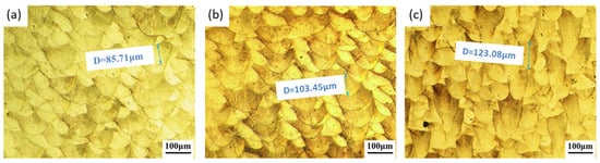
Figure 5.
Morphology of melt pool parallel to the forming direction during SLM formation of Inconel 718 under different laser powers. (a) P = 310 W, (b) P = 335 W, (c) P = 360 W.
3.3. Microstructural Analysis
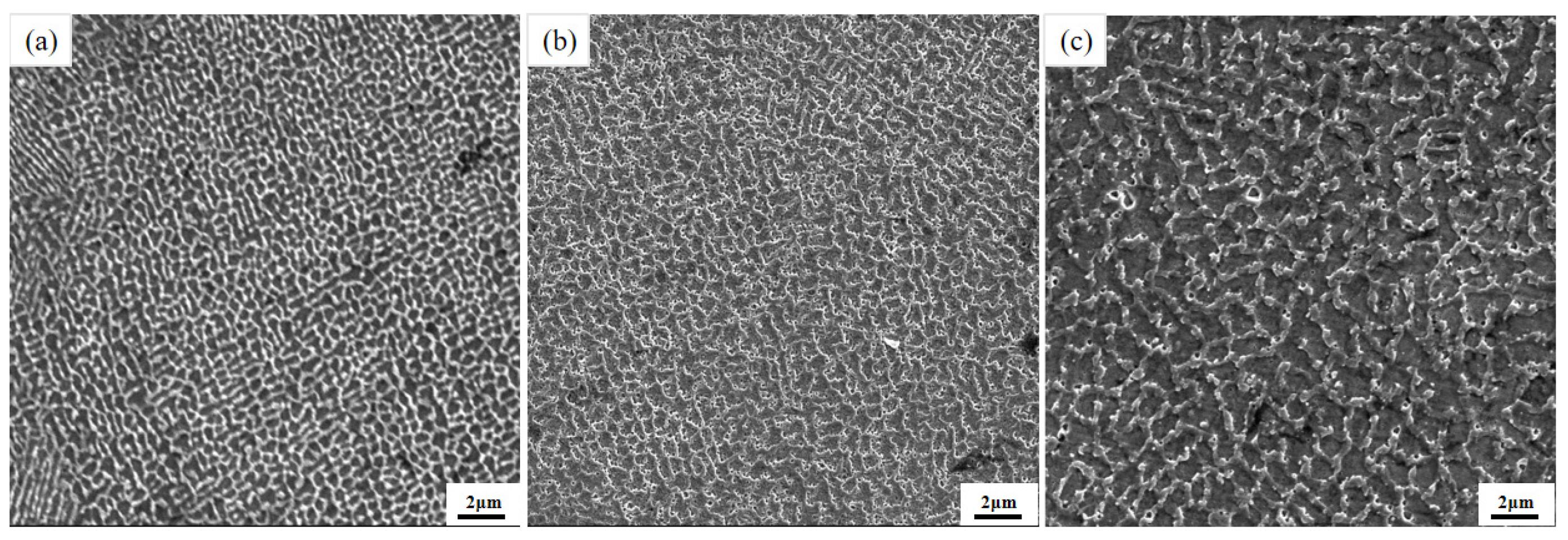
The microstructure of the molten pool center of Inconel 718 formed by SLM under different laser powers perpendicular to the forming direction is shown in Figure 6. From the figure, it can be seen that the microstructure in the molten pool parallel to the scanning direction was composed of cellular dendritic structures or equiaxed crystals. As the laser power gradually increased to 310 W, 335 W, and 360 W, the size of the cellular dendritic structures or equiaxed crystals gradually increased. At a low laser power of 310 W, the edges of the cellular crystal structure were finer, the boundaries were clear, and the number of equiaxed crystals was the highest (Figure 6a). When the laser power increased to the maximum of 360 W, the edges of the cellular crystal structure were thicker, and the crystals were in a fuzzy molten state. It can be seen that the microstructure parallel to the scanning direction gradually coarsened with the increase in laser power (Figure 6c). As the laser power gradually increased, the laser energy density also increased. When a higher intensity laser beam irradiated the material surface, a large amount of heat accumulated near the growth edge of the Inconel 718 crystals. Such heat provided sufficient thermodynamic potential for the growth and boundary coarsening of the Inconel 718 crystal. Therefore, fuzzy molten dendritic cell structures with coarser edges and larger microscopic cell structures appeared.
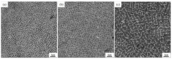
Figure 6.
Microstructure of Inconel 718 formed by SLM at different laser powers perpendicular to the center of the molten pool in the forming direction. (a) P = 310 W, (b) P = 335 W, (c) P = 360 W.
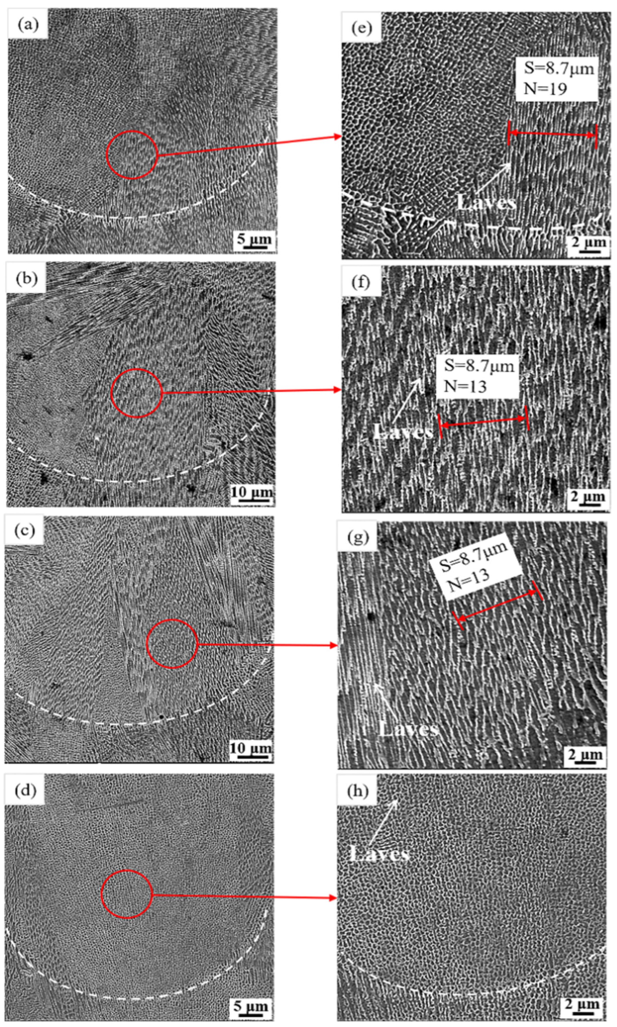
The microstructure of Inconel 718 formed by SLM in a molten pool parallel to the forming direction under different laser powers is shown in Figure 7. The SLM morphology perpendicular to the forming direction was organized in the same molten pool. Furthermore, the direction of the dendritic/cellular structure varied in different positions and was not completely perpendicular to the boundary of the molten pool. This phenomenon was mainly due to the coupling effect of solidification conditions, crystal structure, and convection inside the molten pool [28]. The heat transfer direction in a molten pool is jointly determined by the temperature gradient in the forming direction and the laser scanning direction. The heat dissipation direction of the molten pool at the bottom of the molten pool was parallel to the forming direction, and the heat was transferred to the substrate direction. Therefore, the dendritic growth direction at the bottom of the molten pool was generally parallel to the forming direction. As shown in the enlarged microstructures of Figure 7e–h, there were columnar dendrites with a single growth direction distributed in the samples, as shown in Figure 7e–g. However, there mainly was a cellular crystal structure in the sample in Figure 7h. Take the same distance S = 8.7 μm as shown in Figure 7. When the laser power increased to 360 W, the microstructure in the molten pool was composed of cellular crystals. In addition, existing research shows that the precipitates located in the interdendritic region of Inconel 718 are mainly Laves phases in morphology, composed of Nb- and Mo-rich phases. As indicated by the white arrows in Figure 7e–h, the white network structures are Laves phases.
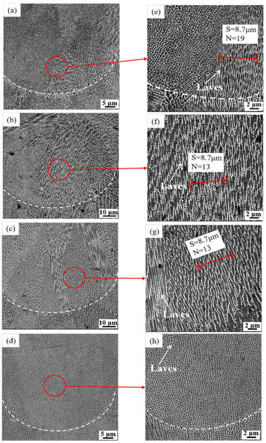
Figure 7.
Microstructure in the melt pool parallel to the forming direction of Inconel 718 formed by SLM under different laser powers: (a) P = 285 W, (b) P = 310 W, (c) P = 335 W, (d) P = 360 W, (e–h) partial enlarged views of (a–d).
According to existing research, the formation of a solidification structure is determined by the process parameters of the SLM forming process through changing temperature gradient (G), solidification rate (R), and undercooling conditions (∆T). The solidification mode of the microstructure was determined by G/R, and the size of the solidification structure was determined by G · R [29]. As the laser power increased, the temperature gradient in the molten pool increased, the solidification rate decreased, and the value of G/R increased. Based on previous studies on the effects of temperature gradient and solidification rate on the solidification structure [30], it was inferred that the microstructure gradually transformed from columnar dendrites to cellular crystals. In addition, as the laser power increased, the laser energy density gradually increased, and the heat input in the molten pool gradually increased, resulting in a longer solidification time. The increase in solidification time led to an increase in the arm spacing of secondary dendrites, which was reflected in the microstructure of the columnar crystals, as shown in Figure 7e–h.
3.4. Texture and Grain Boundary Analysis
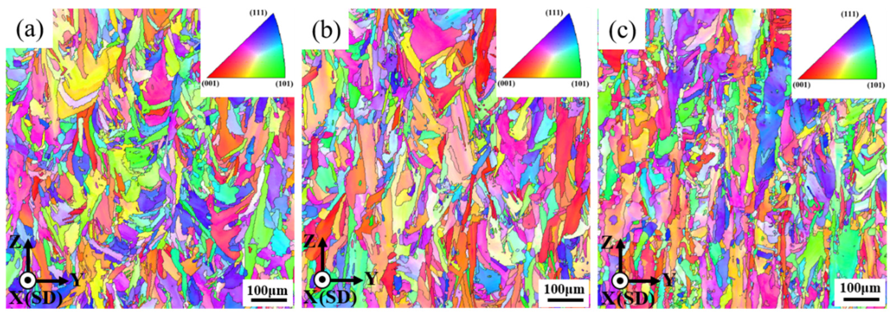
The texture maps of Inconel 718 samples formed by SLM under different laser powers parallel to the forming direction are shown in Figure 8a–c. It can be seen that the three groups of samples dis not have an obvious preferred orientation, and the crystal morphology parallel to the forming direction was mainly composed of a small amount of equiaxed crystals and elongated columnar crystals. In a rapid solidification process, equiaxed grains with fine grains are conducive to the establishment of a strengthening mechanism according to the Hall–Petch mechanism. At the same time, heat is directed from the current processing layer to the deposited layer and substrate. Therefore, some crystals mainly grow along the forming direction and eventually pass through the melt pool to form columnar crystals. In addition, the columnar crystal structure has anisotropy and high texture strength in the growth direction, which is also a key factor in improving the mechanical properties.
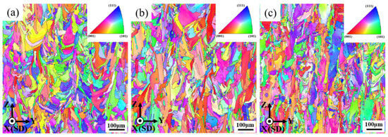
Figure 8.
Orientation imaging of cross sections parallel to the forming direction of Inconel 718 samples formed by SLM under different laser powers: (a) P = 310 W, (b) P = 335 W, (c) P = 360 W.
As shown in Figure 9, the pole maps of the YZ plane of the samples under the three different laser powers were obtained using EBSD. The size of the texture index is known to represent the anisotropy intensity of a sample, which is calculated using the orientation distribution function. As shown in Figure 9a–c, when the laser power was 310 W, 335 W, and 360 W, the texture intensity was not high, and the texture index values did not differ significantly. From the pole diagram in Figure 9b, it can be seen that when the laser power was 335 W, the texture of 001 was strong, with the highest texture index of 4.251. When the laser power was 310 W and 360 W, the texture index was 3.834 and 3.809, respectively.
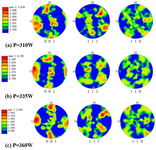
Figure 9.
Cross section pole diagram of Inconel 718 samples formed by SLM under different laser powers parallel to the forming direction. (a) P = 310 W, (b) P = 335 W, (c) P = 360 W.
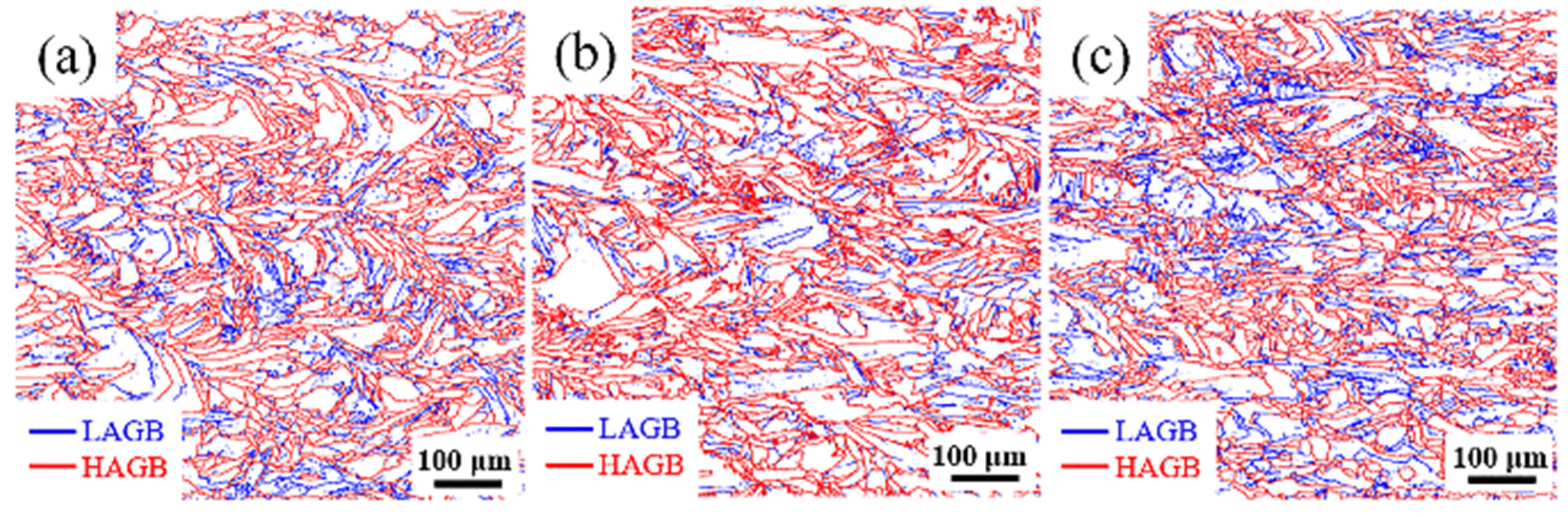
The misorientation angle between the Inconel 718 grains formed by SLM under different laser powers is shown in Figure 10. An interface misalignment angle between grains between 2° and 10° is considered a low-angle grain boundary (LAGB) and is represented by blue lines in the figure. Conversely, a misalignment angle greater than 10° is considered a high-angle grain boundary (HAGB) and is represented by red lines in the figure. The specific grain boundary fraction and average grain size (d) are shown in Table 5. It can be seen that the average grain size did not change much when the laser power was 310 W, 335 W, 360 W, and the minimum average grain size was 47.49 μm when the laser power was 310 W (Figure 10a). At a laser power of 360 W, the highest low-angle grain boundary fraction was 20.1% (Figure 10c). At the same time, it can be observed that the fraction of high-angle grain boundaries was greater than that of low-angle grain boundaries. When forming a new layer, the previously solidified layer was heated or partially remelted. This process is similar to the annealing treatment and can lead to recrystallization, resulting in the formation of high-angle grain boundaries (HAGBs). However, due to the short reheating or remelting time of the previous layer, the recrystallization was not completed, resulting in residual low-angle grain boundaries (LAGBs) [31]. As the laser power increased from 310 W to 335 W, the energy density input also increased, and the average grain size increased from 47.49 μm to 50.57 μm (Figure 10b). The increase in the HAGB content was mainly due to the increase in energy density. This led to a relatively longer reheating or remelting time, thereby prolonging the recrystallization time. However, as the laser power further increased to 360 W, the increase in defects such as pores resulted in a decrease in the high-angle grain boundary fraction.
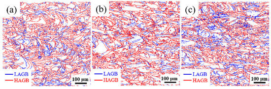
Figure 10.
SLM forming process of Inconel 718 with low-angle grain boundaries (2°~10°, represented by blue lines) and high-angle grain boundaries (>10°, represented by red lines) under different laser powers. (a) P = 310 W, (b) P = 335 W, (c) P = 360 W.
Table 5.
Average grain size (d) and grain boundary fraction of Inconel 718 formed by SLM under different laser powers.
3.5. Mechanical Property Analysis
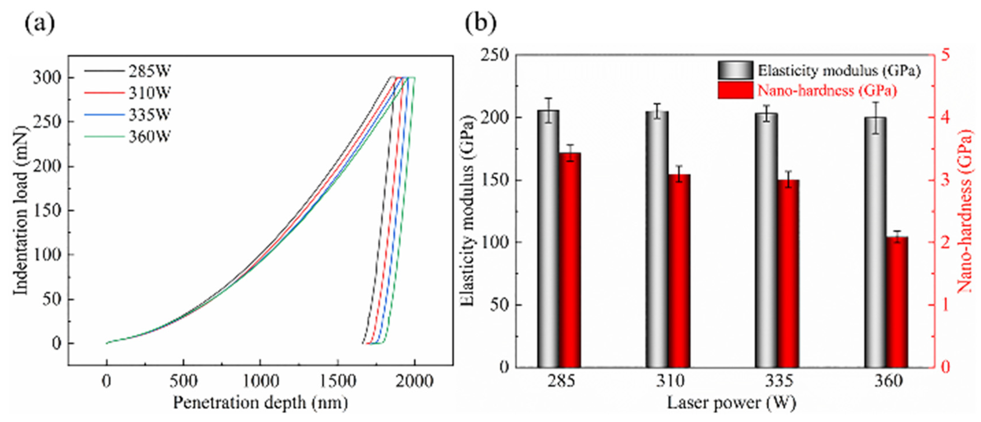
The hardness and elastic modulus of the samples were measured using a nanoindentation instrument. The displacement–load curve obtained by nanoindentation shown in Figure 11a includes three stages: loading, holding at maximum load, and unloading. The maximum load was 300 mN, and the maximum penetration depths of the samples at the end were 1841.99 nm, 1889.20 nm, 1926.03 nm, and 1964.27 nm. The maximum hardness was obtained when the laser power was 285 W. The nano-hardness and elastic modulus of the samples under different laser powers are shown in Figure 11b. As the laser power increased from 285 W to 360 W, the nano-hardness gradually decreased, but the change in elastic modulus was not significant. The nano-hardness of the four groups of samples was 3.43 GPa, 3.10 GPa, 3.01 GPa, and 2.09 GPa; the elastic modulus was 205.72 GPa, 205.11 GPa, 203.24 GPa, and 199.91 GPa, respectively.
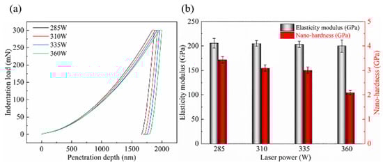
Figure 11.
SLM-formed Inconel 718 samples under different laser powers: (a) displacement–load curves, (b) nano-hardness and elastic modulus Er.
According to Section 3.1, as the laser power increased from 285 W to 360 W, the density of the samples gradually decreased, but the porosity gradually increased. The load acting on the surface of the sample caused a significant collapse, resulting in a gradual decrease in the hardness. In addition, according to Section 3.3, as the laser energy density increased with the increase in laser power, heat accumulation and overheating occurred, leading to the coarsening of the microstructure. According to the principle of fine grain strengthening, as the microstructure coarsens, the mechanical properties, i.e., hardness, decrease.
The mechanical properties of the SLM-formed samples were mainly restricted by the precipitation strengthening mechanism, fine grain strengthening mechanism, grain boundary fraction, and pore defects. Since chemical element segregation and precipitation of components in the morphologically different samples were small, the impact of the precipitation hardening mechanism on the strength difference was negligible. A large number of low-angle grain boundaries can hinder the movement of dislocations, thereby enhancing the strengthening effect through the action of grain boundaries [32]. The pores are caused by the increase in laser energy density as the laser power increases, resulting in an increase in input heat. The resulting spherical evaporation holes have no sharp corners and will not cause severe stress concentration under tensile load [33]. Therefore, when the laser power is increased to the maximum, the highest tensile strength and yield strength will be obtained, while the elongation and area reduction will not show obvious trends.
4. Conclusions
This article systematically investigated the effect of laser power on the phase composition, densification behavior, microstructure, and mechanical properties of Inconel 718 alloy formed by SLM. The results are similar to those of Kang et al. [34]. Compared to others, the current study further limits the influence of other process parameters, for example, hatch distance and laser speed. Therefore, the influence of various laser powers is more evident. The main conclusions are as follows:
As the laser power increased, the peak intensity of XRD gradually decreased, and auxiliary strengthening phases such as γ′ precipitated from the matrix. At the same time, the increase in working temperature in the molten pool promoted the evaporation of gas and the vaporization of the low-melting-point alloy components, and the relative density gradually increased from 99.31% to 99.79%.
As the laser energy density increased, the greater laser energy irradiated the material surface, resulting in a stronger Marangoni convective flow and a deeper molten pool formation. The microstructure gradually coarsened, transforming from columnar dendrites to cellular crystals.
As the laser power increased from 310 W to 360 W, little change was observed in the average grain size and texture strength of the Inconel 718 alloy samples formed by SLM.
As the laser power increased, the nano-hardness of the material gradually decreased. The nano-hardness of the material decreased with the increase in laser power. The nano-hardness of the four groups of samples from 285 W to 360 W decreased form 3.43 GPa to 2.09 GPa, and the elastic modulus decreased form 205.72 GPa to 199.91 GPa.
However, an increase in laser power could promote the formation of the auxiliary strengthening phase γ′. The increase in the fraction of phases and low-angle grain boundaries hindered the movement of dislocations, thereby enhancing the strengthening effect through the interaction of grain boundaries and strengthening phases.
Author Contributions
Methodology, T.L. and Y.Z.; Resources, S.Z.; Data curation, L.Y.; Writing—original draft, Y.W.; Writing—review & editing, L.G. and S.Z.; Project administration, J.M. and S.Z. All authors have read and agreed to the published version of the manuscript.
Funding
The authors gratefully acknowledge the financial support from the Scientific and Technological Innovation Foundation of Foshan, USTB (No. BK21BE015).
Data Availability Statement
The original contributions presented in the study are included in the article material, further inquiries can be directed to the corresponding author.
Conflicts of Interest
The authors declare no conflict of interest.
References
- Kruth, J.P.; Froyen, L.; Van Vaerenbergh, J.; Mercelis, P.; Rombouts, M.; Lauwers, B. Selective laser melting of iron-based powder. J. Mater. Process. Technol. 2004, 149, 616–622. [Google Scholar] [CrossRef]
- Hussein, A.; Hao, L.; Yan, C.; Everson, R. Finite element simulation of the temperature and stress fields in single layers built without-support in selective laser melting. Mater. Des. (1980–2015) 2013, 52, 638–647. [Google Scholar] [CrossRef]
- Mullen, L.; Stamp, R.C.; Brooks, W.K.; Jones, E.; Sutcliffe, C.J. Selective Laser Melting: A regular unit cell approach for the manufacture of porous, titanium, bone in-growth constructs, suitable for orthopedic applications. J. Biomed. Mater. Res. Part B Appl. Biomater. 2009, 89B, 325–334. [Google Scholar] [CrossRef] [PubMed]
- Sun, J.; Yang, Y.; Wang, D. Mechanical properties of a Ti6Al4V porous structure produced by selective laser melting. Mater. Des. 2013, 49, 545–552. [Google Scholar] [CrossRef]
- De Bartolomeis, A.; Newman, S.T.; Jawahir, I.S.; Biermann, D.; Shokrani, A. Future research directions in the machining of Inconel 718. J. Mater. Process. Technol. 2021, 297, 117260. [Google Scholar] [CrossRef]
- Ni, M.; Chen, C.; Wang, X.; Wang, P.; Li, R.; Zhang, X.; Zhou, K. Anisotropic tensile behavior of in situ precipitation strengthened Inconel 718 fabricated by additive manufacturing. Mater. Sci. Eng. A 2017, 701, 344–351. [Google Scholar] [CrossRef]
- Zhang, D.; Zhang, P.; Liu, Z.; Feng, Z.; Wang, C.; Guo, Y. Thermofluid field of molten pool and its effects during selective laser melting (SLM) of Inconel 718 alloy. Addit. Manuf. 2018, 21, 567–578. [Google Scholar] [CrossRef]
- Hosseini, E.; Popovich, V.A. A review of mechanical properties of additively manufactured Inconel 718. Addit. Manuf. 2019, 30, 100877. [Google Scholar] [CrossRef]
- Jinoop, A.N.; Paul, C.P.; Mishra, S.K.; Bindra, K.S. Laser Additive Manufacturing using directed energy deposition of Inconel-718 wall structures with tailored characteristics. Vacuum 2019, 166, 270–278. [Google Scholar] [CrossRef]
- Xia, M.; Gu, D.; Ma, C.; Chen, H.; Zhang, H. Microstructure evolution, mechanical response and underlying thermodynamic mechanism of multi-phase strengthening WC/Inconel 718 composites using selective laser melting. J. Alloys Compd. 2018, 747, 684–695. [Google Scholar] [CrossRef]
- Liu, P.; Hu, J.; Sun, S.; Feng, K.; Zhang, Y.; Cao, M. Microstructural evolution and phase transformation of Inconel 718 alloys fabricated by selective laser melting under different heat treatment. J. Manuf. Process. 2019, 39, 226–232. [Google Scholar] [CrossRef]
- Park, J.H.; Bang, G.B.; Lee, K.-A.; Son, Y.; Kim, W.R.; Kim, H.G. Effect on microstructural and mechanical properties of Inconel 718 superalloy fabricated by selective laser melting with rescanning by low energy density. J. Mater. Res. Technol. 2021, 10, 785–796. [Google Scholar] [CrossRef]
- Liu, F.; Hu, W.; Jia, J. Micro pore defects and tensile properties of high density laser selective melting Inconel 718 alloy. Rare Met. Mater. Eng. 2021, 50, 3684–3692. [Google Scholar]
- Zheng, J.; Jin, T.N.; Fang, X. Effect of scanning spacing on microstructure of IN718 alloy by selective laser melting. Heat Treat. Met. 2021, 46, 127–132. [Google Scholar]
- Wei, J.; Wu, M.; Han, J.-t. Influence mechanism of scanning strategy on surface quality of Inconel 718 formed by SLM. Appl. Laser 2020, 40, 621–625. [Google Scholar]
- Xu, Y.; Zhang, R.; Xiao, Z. Quantitative Characterization of particle shape of Inconel 718 Alloy powder and optimization of SLM forming process. Powder Metall. Mater. Sci. Eng. 2020, 25, 465–474. [Google Scholar]
- Liu, Z.; Kim, H.; Liu, W.; Cong, W.; Jiang, Q.; Zhang, H. Influence of energy density on macro/micro structures and mechanical properties of as-deposited Inconel 718 parts fabricated by laser engineered net shaping. J. Manuf. Process. 2019, 42, 96–105. [Google Scholar] [CrossRef]
- Borisov, E.V.; Popovich, V.A.; Popovich, A.A.; Sufiiarov, V.S.; Zhu, J.N.; Starikov, K.A. Selective laser melting of Inconel 718 under high laser power. Mater. Today Proc. 2020, 30, 784–788. [Google Scholar] [CrossRef]
- Chen, J.; Wang, X.; Pan, Y. Influence of laser power and scan speed on the microstructure and properties of GH4169 alloy prepared by selective laser melting. IOP Conf. Ser. Mater. Sci. Eng. 2019, 688, 033064. [Google Scholar] [CrossRef]
- Guo, C.; Li, S.; Shi, S.; Li, X.; Hu, X.; Zhu, Q.; Ward, R.M. Effect of processing parameters on surface roughness, porosity and cracking of as-built IN738LC parts fabricated by laser powder bed fusion. J. Mater. Process. Technol. 2020, 285, 116788. [Google Scholar] [CrossRef]
- Benoit, M.J.; Mazur, M.; Easton, M.A.; Brandt, M. Effect of alloy composition and laser powder bed fusion parameters on the defect formation and mechanical properties of Inconel 625. Int. J. Adv. Manuf. Technol. 2021, 114, 915–927. [Google Scholar] [CrossRef]
- Khorasani, A.; Gibson, I.; Awan, U.S.; Ghaderi, A. The effect of SLM process parameters on density, hardness, tensile strength and surface quality of Ti-6Al-4V. Addit. Manuf. 2019, 25, 176–186. [Google Scholar] [CrossRef]
- Volpato, G.M.; Tetzlaff, U.; Fredel, M.C. A comprehensive literature review on laser powder bed fusion of Inconel superalloys. Addit. Manuf. 2022, 55, 102871. [Google Scholar] [CrossRef]
- Jaladurgam, N.R.; Li, H.; Kelleher, J.; Persson, C.; Steuwer, A.; Colliander, M.H. Microstructure-dependent deformation behaviour of a low γ′ volume fraction Ni-base superalloy studied by in-situ neutron diffraction. Acta Mater. 2020, 183, 182–195. [Google Scholar] [CrossRef]
- Guo, M.; Gu, D.; Xi, L.; Zhang, H.; Zhang, J.; Yang, J. Selective laser melting additive manufacturing of pure tungsten: Role of volumetric energy density on densification, microstructure and mechanical properties. Int. J. Refract. Met. Hard Mater. 2019, 84, 105025. [Google Scholar] [CrossRef]
- Wang, D.; Song, C.; Yang, Y.; Bai, Y. Investigation of crystal growth mechanism during selective laser melting and mechanical property characterization of 316L stainless steel parts. Mater. Des. 2016, 100, 291–299. [Google Scholar] [CrossRef]
- Olivier, A.; Imade, K.; Patrice, P.; Penot, J.D.; Saintier, N.; Pessard, E.; Terris, T.D.; Dupuy, C. Texture control of 316L parts by modulation of the melt pool morphology in selective laser melting. J. Mater. Process. Technol. 2018, 264, 21–31. [Google Scholar]
- Liu, J.; Song, Y.; Chen, C.; Wang, X.; Li, H.; Wang, J.; Guo, K. Effect of scanning speed on the microstructure and mechanical behavior of 316L stainless steel fabricated by selective laser melting. Mater. Des. 2020, 186, 108355. [Google Scholar] [CrossRef]
- Debroy, T.; Wei, H.L.; Zuback, J.S.; Mukherjee, T.; Elmer, J.W.; Milewski, J.O.; Beese, A.M. Additive manufacturing of metallic components—Process, structure and properties. Prog. Mater. Sci. 2018, 92, 112–224. [Google Scholar] [CrossRef]
- Chen, Y.; Yue, H.; Wang, X. Microstructure, texture and tensile property as a function of scanning speed of Ti-47Al-2Cr-2Nb alloy fabricated by selective electron beam melting. Mater. Sci. Eng. A 2018, 713, 195–205. [Google Scholar] [CrossRef]
- Li, W.; Liu, J.; Wen, S.; Wei, Q.; Yan, C.; Shi, Y. Crystal orientation, crystallographic texture and phase evolution in the Ti–45Al–2Cr–5Nb alloy processed by selective laser melting. Mater. Charact. 2016, 113, 125–133. [Google Scholar] [CrossRef]
- Chen, H.; Gu, D.; Dai, D.; Xia, M.; Ma, C. A novel approach to direct preparation of complete lath martensite microstructure in tool steel by selective laser melting. Mater. Lett. 2018, 227, 128–131. [Google Scholar] [CrossRef]
- Liu, S.Y.; Li, H.Q.; Qin, C.X.; Zong, R.; Fang, X.Y. The effect of energy density on texture and mechanical anisotropy in selective laser melted Inconel 718. Mater. Des. 2020, 191, 108642. [Google Scholar] [CrossRef]
- Kang, J.; Yi, J.; Wang, T.; Wang, X.; Feng, T.; Feng, Y.L.; Wu, P.Y. Effect of laser power and scanning speed on the microstructure and mechanical properties of SLM fabricated Inconel 718 specimens. Mater. Sci. Eng. Int. J. 2019, 3, 72–76. [Google Scholar] [CrossRef]


Disclaimer/Publisher’s Note: The statements, opinions and data contained in all publications are solely those of the individual author(s) and contributor(s) and not of MDPI and/or the editor(s). MDPI and/or the editor(s) disclaim responsibility for any injury to people or property resulting from any ideas, methods, instructions or products referred to in the content. |
© 2024 by the authors. Licensee MDPI, Basel, Switzerland. This article is an open access article distributed under the terms and conditions of the Creative Commons Attribution (CC BY) license (https://creativecommons.org/licenses/by/4.0/).