Abstract
The interaction between train vibration load and ground fissure disasters affects the safe operation of trains. However, the interaction between the high-speed railway foundation and the train vibration in the cross-ground fissure zone is not clear. To reveal the dynamic behavior characteristics of train vibration load crossing the ground fissure zone, the Da’xi high-speed railway passing through the ground fissure zone in the Taiyuan Basin is taken as the research object; the dynamic response of the high-speed railway foundation crossing the ground fissure zone at different angles was analyzed through dynamic finite element numerical simulation and orthogonal tests. The results show that when the high-speed railway crosses the ground fissure, the dynamic response fluctuates greatly at the ground fissure, which is manifested in the displacement and acceleration increase in the hanging wall and decrease in the footwall. The composite foundation reduces the fluctuation range and influences the scope of displacement, acceleration, and stress in the foundation of the ground fissure zone. The smaller the intersection angle between the high-speed railway and the ground fissure, the larger the influence range of displacement and stress, and the stability of acceleration at the hanging wall and footwall is poor. It is suggested that the high-speed railway pass through the ground fissure at a large angle. Additionally, the displacement fluctuation of the hanging wall and footwall can be controlled by increasing the pile length in the active area of the ground fissure.
1. Introduction
Ground fissures are a phenomenon of rock–soil surface rupture [1,2,3,4]. Ground fissures are widely distributed in China, and more than 5000 ground fissures have been found in over 4000 locations [5], mostly in the North China Plain, Fenwei Basin, Su-Xi-Chang, and other areas [6,7,8]. Many high-speed railways under construction and proposed inevitably cross these ground fissure development areas in China, such as Jing’shi (Beijing–Shijiazhuang), Jing’hu (Beijing–Shanghai), Da’xi (Datong–Xi’an), and other high-speed railways [9]. When crossing ground fissure areas, they are easily affected by complex geological engineering conditions [10,11]. Under the train vibration load, the strength of loose rock and soil mass in the ground fissure zone is reduced and triggers uneven settlement, which affects the stability of the high-speed railway and has a negative impact on the safe operation of the train [12]. Therefore, it is necessary to study the dynamic response of the high-speed railway foundation under the train vibration load in the ground fissure zone.
Existing engineering phenomena show that the engineering structures crossing the ground fissures can be seriously damaged, including cracking of the subway tunnel lining, distortion and deformation of underground pipelines, uneven settlement of the expressway, and so on [13,14]. Previous scholars have conducted related research on these aspects and believe that the shear dislocation is the main failure mode of the active ground fissures to the traffic lines, which causes the deformation and cracking of the structures at the hanging wall and footwall under the corresponding compressive and tensile stress. Meanwhile, for the small angle crossing, the failure mode of bend–shear–torsion will appear [15].
At present, research on dynamic response under train vibration load mainly focuses on three methods: field tests [16], numerical simulation [17,18,19,20,21,22,23,24], and model tests [25,26]. Vega et al. conducted acceleration response tests on high-speed railway subgrades and studied the dynamic response characteristics of culverts, which provided a reference for the design of a high-speed railway [27,28]. Yu Cai et al. took the test section of a cement-improved expansive soil embankment as the research object. The multi-condition cyclic vibration test was carried out, and the distribution rules of stress, acceleration, and displacement at different positions of subgrade were analyzed [29]. Yao Shan et al. established the finite–infinite element model of plane stress in the transition zone between the subgrade and bridge of a high-speed railway. The influence of subgrade materials on the subgrade dynamic response in the transition zone of a slab track high-speed railway was studied. It was considered that the dynamic elastic modulus of graded crushed stone has greater influence on the vibration response of vehicle systems than that of the surface layer of the subgrade bed [30]. Jin Chen et al. established a three-dimensional dynamic finite element analysis model of a double-line high-speed railway under train vibration load, and the vertical stress distribution on the subgrade surface under different train speeds and line modes was proposed [31]. Ishikawa T. carried out a model test on a ballasted track with a geometric scale of 1:5 and studied the law of dynamic response and the cumulative deformation of subgrade filler under the train cyclic load [32]. Chong Lei Zhang et al. conducted a full-scale model test on lime-stabilized weathered red mudstone subgrade by using a cyclic loading device. The dynamic response and cumulative settlement characteristics of this kind of subgrade were studied and its adaptability was determined [33].
In general, a series of studies have been performed on the vibration response of the track structure–embankment–foundation under train vibration load, and fruitful research results have been achieved. However, there are few studies on the dynamic response of the high-speed railway foundation under train vibration in the ground fissure site, and the interaction between the high-speed railway foundation and the train vibration in the cross-ground fissure is not clear.
The Da’xi high-speed railway which crosses the ground fissures in the Taiyuan Basin of Shanxi Province is taken as the engineering background in this study. A three-dimensional numerical model of the high-speed railway crossing the ground fissure was established. The dynamic response of the foundation was studied. The research results provide a reference for the design, construction, and safe operation of a high-speed railway in the ground fissure environment.
2. Engineering Background
The starting point of the Datong–Xi’an high-speed railway is Datong, Shanxi, and the endpoint is Xi’an, Shaanxi (Figure 1a) [
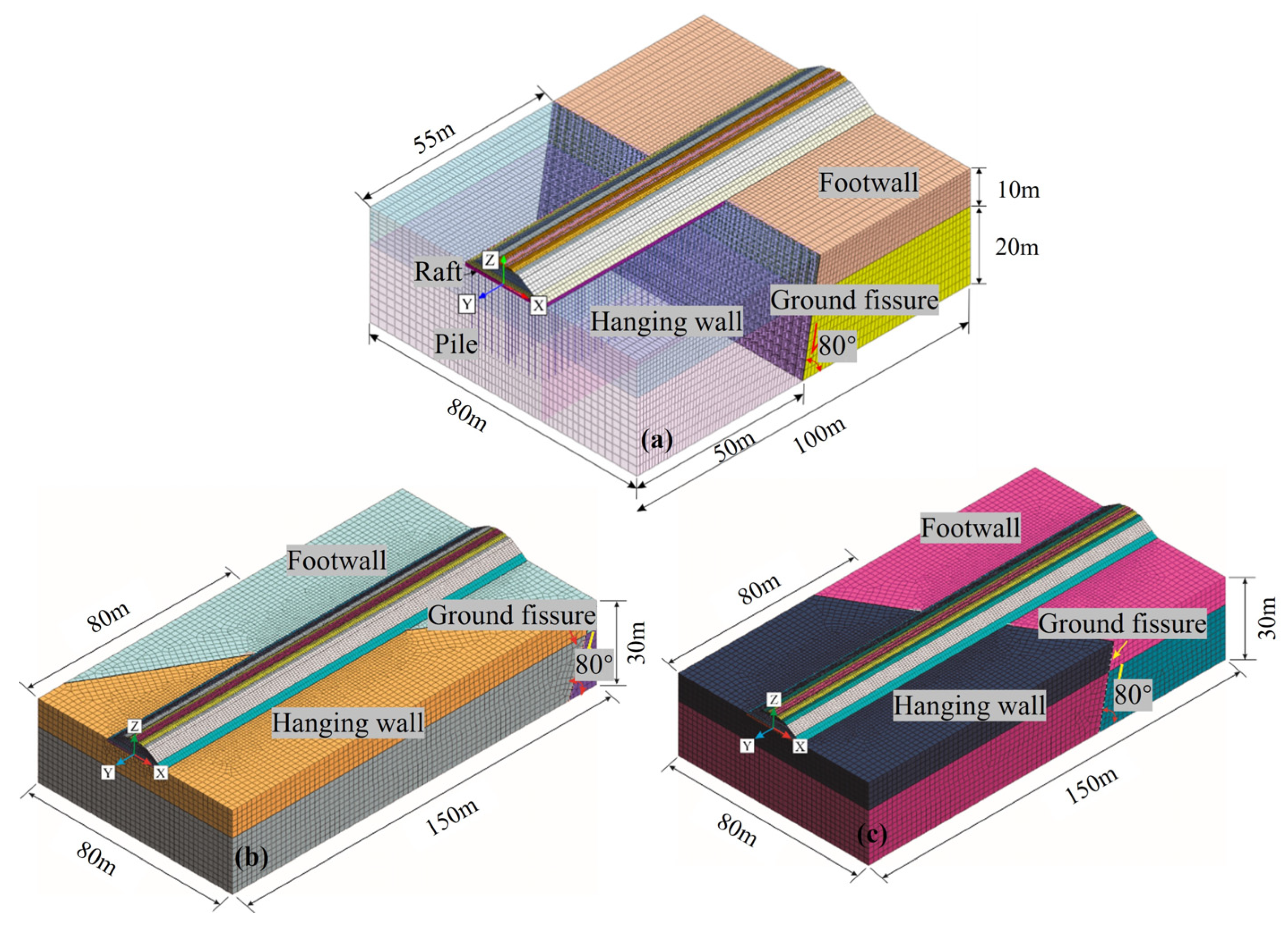
34]. The total length of the line is 859 km, with it being a passenger-dedicated line. The number of trains per day is 88 pairs. The average speed is 250 km/h, and the maximum speed is no more than 350 km/h. It passes through the Cenozoic rift basin—Taiyuan Basin, where faults are greatly developed. The overexploitation of groundwater in the Taiyuan Basin has promoted the activities of these fissures controlled by tectonism. Based on the investigation, there are 107 ground fissures in the Taiyuan Basin and 21 along the Da’xi railway line. Most of the ground fissures have a large extension length, with some exceeding 20 km. Among them, the maximum deviation of the ground fissure (TY3) at the Dongguan substation is 0.45 m, and the vertical activity rate of ground fissures is 3–4 cm/year. The overall strike of the TY3 ground fissure is 73°, its inclination is 163°, the dip angle is 80° (Figure 1b), and it is banded or beaded. The maximum surface displacement is about 45 cm (Figure 1c), and the maximum pit diameter is 1.2 m, the maximum width of the horizontal displacement is 1 m (Figure 1d) [35]. The TY3 ground fissure is active in sections, mainly vertical dislocation and horizontal tension (Figure 1e). With the drop in groundwater level, the influence scope and activity of ground fissures may be further intensified. It is predicted that the ground fissures are highly active and dangerous to the line. In this paper, the dynamic response analysis of the composite foundation of the high-speed railway crossing the ground fissure zone is carried out with the active TY3 ground fissures as the engineering background.
Figure 1.
(a) China’s high-speed railway network [34]; (b) the distribution of faults and ground fissures in the study area (the map was drawn using ArcGIS 10.5 (https://www.esri.com/)); (c) vertical differential settling due to fissure; (d) ground surface cracking due to fissure; (e) TY3 ground fissures profile.
3. Numerical Modeling Process
3.1. Dynamic Finite Element Model
In this study, finite element software (MIDAS/GTS2019 v2.1) was used to establish the dynamic finite element model of a high-speed railway natural foundation and a CFG pile composite foundation spanning the ground fissure zone (Figure 2). The mesh of the numerical model is hexahedron and the element is the entity. The specific modeling process can be found in Appendix A.
Figure 2.
(a) High-speed railway and ground fissure orthogonal θ = 90°; (b) θ = 60°; (c) θ = 30°.
In the numerical model, the intersection angle between the high-speed railway and the ground fissure was set at 90° (orthogonal), 60°, and 30° (oblique), respectively. The dip angle of the ground fissure was 80° and ran through the entire stratum. In order to save on calculation costs, the length of the model was reduced by 50 m in orthogonally passing through the ground fissure, and the other parameters remained unchanged. The stratum within the simulated depth range was simplified into two layers, and its physical and mechanical parameters are shown in Table 1.
Table 1.
Soil layer parameters [9].
The composite foundation of the numerical model of the cross-ground fissure zone of the Da’xi passenger-dedicated line adopts a pile–raft structure. The piles were CFG piles with a length of 20 m, a diameter of 0.5 m, a spacing of 2 m, and a square layout. A pile-soil contact element was established around the pile element to simulate the slip between the pile and the soil. A C30 reinforced concrete slab with a thickness of 0.8 m and plain concrete cushion of 0.2 m was set above the pile. Both were considered as a unified raft during modeling. The surface layer of the subgrade bed was 0.7 m thick and was filled with graded crushed stone. The bottom layer of the subgrade bed was 2.3 m thick. The slope gradient of the embankment was 1:1.5. To adapt to the active deformation of the ground fissure, the track structure was designed as a ballasted track. The cross-section of the composite foundation in the calculation is shown in Figure 3.
Figure 3.
Standard section of the CFG pile in the composite foundation (unit: m).
The calculation parameters of each structural layer of subgrade are shown in Table 2.
Table 2.
Subgrade parameters [9].
Rails, sleepers, CFG piles, and concrete baseplates were considered as isotropic linear elastic materials. The solid elements of the ballast bed and below were subject to the Drucker–Prager (D-P) elastoplastic failure criterion. The fasteners between the rail and sleeper were modeled using the spring-damping elements [36,37]. The simulation conditions are shown in Table 3.
Table 3.
Numerical simulation conditions.
3.2. Train Load Simulation
CRH380A series high-speed trains were used on the Da’xi passenger-dedicated line. The maximum axle load of the train was 15 t, and the static load on one side was 75 kN. The train was composed of eight carriages. The length of each carriage was 25 m, the center distance between bogies was 17.5 m, the fixed wheelbase was 2.5 m, and the total length was 203 m. Table 4 shows the train parameters.
Table 4.
High-speed train parameters [9].
Considering the dynamic effect of wheel load, the calculation formula for exciting force load was as follows [38]:
where
- Ps—wheel static load (kN);
- α—velocity amplification factor (about 0.004);
- v—train speed (km/h)
The time–history curve of excitation force load at a 250 km/h train speed was calculated (Figure 4), and the moving load was set according to it.
Figure 4.
Excitation force load time–history curve.
3.3. Simulation of Ground Fissures
Ground fissures are filled with silty fine sand and silt. The interface contact element can simulate the relative dislocation or slip between elements and better reflect the physical and mechanical properties of the ground fissure. Therefore, the interface contact element was used to simulate ground fissures. Its mechanical mechanism is shown in Figure 5. The contact elements met the Mohr—Coulomb friction relationship, which can be expressed as:
where Fn is the normal stress of the contact surface, Fsmax is the ultimate tangential stress of the contact surface, cif is the cohesion of the contact surface, φif is the friction angle of the contact surface, A is the area of the contact surface, and u is the pore pressure.
Figure 5.
Schematic diagram of contact surface element.
The parameters of ground fissures were set according to references [39,40], where normal stiffness Kn = 10,000 kPa, tangential stiffness Ks = 1000 kPa, cohesion c = 12 kPa, and internal friction angle φ = 20°.
3.4. Boundary Condition
To prevent the vibration wave from reflecting at the model boundary and to ensure numerical calculation accuracy, the viscoelastic boundary was used in the analysis and numerical calculation (Figure 6) [41].
Figure 6.
Viscoelastic boundary.
The spring damping coefficients of each structural layer of the model are shown in Table 5, where x, y, and z represent the three coordinate axis components of the overall coordinate system.
Table 5.
Viscoelastic boundary parameters.
3.5. Material Damping
In this study, Rayleigh damping was selected for dynamic calculation of material damping [42]. The relationship between the damping matrix [Z], mass matrix [X], and stiffness matrix [Y] is:
where m is the damping coefficient related to the mass matrix and n is the damping coefficient related to the stiffness matrix. The damping coefficient can be calculated according to the natural vibration frequency of the model and the corresponding soil damping ratio as follows:
where an represent the damping ratio of the and order and represent the natural frequency of the and order.
According to reference [43], the damping ratio of foundation soil is , and is the natural frequency of the model, which is obtained through eigenvalue analysis.
4. Results and Analysis
Five measuring lines are arranged in the numerical model (Figure 7). Measuring line 1 is located on the center line of the high-speed railway at a depth of 5 m. Measuring lines 2 and 3 are arranged vertically along the subgrade and are located at the hanging wall and footwall, 2 m away from the ground fissure, respectively. Measuring lines 4 and 5 are arranged horizontally along the high-speed railway at a depth of 5 m inside the foundation and located at the hanging wall and footwall 2 m away from the ground fissure, respectively.
Figure 7.
Measuring line position.
4.1. Comparative Analysis of the Displacement Response of the Foundation
In order to ensure the correct setting of ground fissure contact properties and vibration load, the numerical results in this study were verified according to the physical model test results in reference [44]. The train load is simulated by a moving exciter, and the specific test process is shown in the above reference. The displacements of the physical model test and the numerical model were compared, as shown in Figure 8a. By comparing the results of the physical model test and the numerical model test, it can be seen that the stress of the natural foundation obtained through numerical simulation is the same as the changing trend of the stress curve of the natural foundation measured using the model test, which is manifested by the oscillation at the ground fissure, and the average displacement of the hanging wall is greater than that of the footwall. In summary, the comparison results show that the train load application and the ground fissure contact relationship of the numerical model are reasonable.
Figure 8.
(a) Comparison of the physical model and the θ = 90° numerical model; (b) θ = 60°; (c) θ = 30°; (d) schematic diagram of the location of the survey line and the cross-ground fissures at different angles.
On this basis, the displacement changes of the high-speed railway crossing ground fissure sites at three angles were analyzed. In the ground fissure zone, the displacement induced by train vibration load increased in the hanging wall of the natural and composite foundation, while decreasing in the footwall, and the jumping phenomenon was more significant in the natural foundation. Meanwhile, as the intersection angle θ between the high-speed railway and ground fissures decreases, the influence range of ground fissures on both types of foundations increases (Figure 8).
When θ = 90°, the influence range of the composite foundation was reduced by 2 m in the hanging wall and by 5 m in the footwall compared with the natural foundation. When θ = 60°, the hanging wall shrank by 5 m and the footwall shrank by 8 m. When θ = 30°, the hanging wall shrank by 7 m and the footwall shrank by 8 m. It can be seen that the composite foundation with the pile–raft structure enhanced the ability of the foundation to resist the deformation and damage caused by the ground fissure and effectively reduced the influence range of the ground fissure. Therefore, when the actual construction cannot avoid crossing the ground fissure zone at a small angle, the pile raft can be adopted in the foundation.
Figure 9 is the horizontal variation curve of the displacement amplitude inside the foundation (measuring lines 4 and 5; see Figure 7). The displacement of the composite foundation is symmetrically distributed along the center line of the subgrade, and the displacement at the center line of the high-speed railway reaches the maximum. The displacement of the hanging wall is greater than that of the footwall along the horizontal direction. The load of the central line is large, and on both sides, it is small. However, the difference in displacement response within the embankment is smaller than that of the foundation outside the embankment toe. The concrete baseplate and CFG pile reduce the differential deformation of the hanging wall and footwall of the ground fissure. Therefore, during the operation of the high-speed railway, the differential settlement of the embankment on both sides of the ground fissure should be concentrated on to avoid ponding in the location of the ground fissure, which will reduce the foundation strength and affect the stability of the high-speed railway.
Figure 9.
Horizontal variation curve of displacement amplitude inside the foundation (θ = 90°).
Figure 10 shows the variation in the displacement of the natural foundation and composite foundation along the buried depth on measuring lines 2 and 3 (see Figure 7) of the site orthogonal to the ground fissure. The difference in the displacement response of the hanging wall and footwall at the two types of sites increases gradually with the depth increasing, and the displacement difference in the natural foundation is greater than that of the composite foundation. In addition, the displacement of the natural foundation changes more than that of the composite foundation, and the natural foundation is more significantly affected by the ground fissure. Due to the existence of CFG piles, the displacement attenuation in the composite foundation can be divided into three parts according to the foundation depth, namely, the embankment above the foundation, the pile, and the bearing layer. Among them, the displacement of the pile attenuates the most slowly. Because CFG piles bear part of the train vibration load, the settlement and deformation of soil around the pile within the pile length are slight, and the composite foundation shows a good reinforcement effect.
Figure 10.
Attenuation curve displacement amplitude with depth (high-speed railway and ground fissure orthogonal θ = 90°).
4.2. Acceleration Response of the Foundation
Figure 11 is the acceleration change curve of measuring line 1 (see Figure 7) on the natural foundation and composite foundation crossing the ground fissure at three angles. Under the three intersection angles, the acceleration response of the composite foundation was significantly smaller than that of the natural foundation, and the fluctuation at the ground fissure was reduced, which indicated that the composite foundation can effectively control the problem of weak stratum caused by the ground fissure. In both the composite foundation and natural foundation, the change in acceleration exhibits a jump phenomenon in the formation on both sides of the ground fissure, specifically, the acceleration reaches its maximum at the position of the hanging wall close to the ground fissure, especially obvious when θ = 30°. Therefore, crossing the ground fissure zone at a small angle poses a serious threat to the safe operation of the train. It is recommended to cross the ground fissure at a large angle.
Figure 11.
Variation curves of stress amplitudes across ground fissures at different angles in two kinds of foundation forms (measuring line 1): (a) θ = 90°; (b) θ = 60°; (c) θ = 30°; (d) schematic diagram of the location of the measuring line and the cross-ground fissures at different angles.
Figure 12 is the horizontal variation curve of the acceleration amplitude inside the foundation (measuring lines 4 and 5; see Figure 7). The acceleration inside the composite foundation is symmetrically distributed along the center line of the subgrade, and the acceleration amplitude near the center line of the high-speed railway is large but small on both sides. The acceleration on the hanging wall is significantly greater than that of the footwall. The response difference of acceleration first decreases from the center of the line to both sides and increases suddenly at the edge of the subgrade, which is caused by the propagation of vibration waves in different media.
Figure 12.
Horizontal variation curve of acceleration amplitude inside the foundation (θ=90°).
Figure 13 shows the acceleration attenuation curve of natural and composite foundations (measuring lines 2 and 3) with buried depth at the hanging wall and footwall of the ground fissure site. In the two types of sites, the difference of acceleration response of the embankment in the hanging wall and footwall is small, and the difference inside the foundation is large. The acceleration attenuation amplitude of the composite foundation is greater than that of the natural foundation. The acceleration attenuation of the natural foundation hanging wall is about 92.7%, and that of the footwall is about 96.7%, while that of the composite foundation hanging wall is about 95.5% and that of the footwall is about 96.9%. The critical influence depth is reduced from 25 m for the natural foundation to 15 m for the composite foundation. This is because the CFG pile bears part of the train load, the soil around the pile is less affected by the vibration, and the composite foundation has a good restraining effect.
Figure 13.
Attenuation curve of foundation acceleration amplitude with depth (θ = 90°).
4.3. Stress Response of Foundation
Figure 14 shows the stress comparison of measuring line 1 (see Figure 7) crossing the ground fissures at three angles in the natural foundation and composite foundation. When the high-speed railway crosses the ground fissure at one angle, the stress jump phenomenon of the composite foundation is weaker than that of the natural foundation. Taking the mean value of the stable transition zone of the stress change curve as the dynamic influence limit, the influence range of stress of the composite foundation is significantly smaller than that of the natural foundation. With the increase in the intersecting angle, the influence range of the ground fissure in both the natural and composite foundations decreases. Therefore, passing through the ground fissure zone at a large angle can effectively reduce the damage impact caused by ground fissure disasters.

Figure 14.
Stress amplitude change curve of the structural layer along the foundation at different intersection angles (measuring line 1): (a) θ = 90°; (b) θ = 60°; (c) θ = 30°; (d) schematic diagram of the location of the survey line and the cross-ground fissures at different angles.
Figure 15 is the horizontal variation curve of the stress inside the foundation (measuring lines 4 and 5; see Figure 7). The stress in the composite foundation is symmetrical along the center line of the subgrade, and the stress at the center line of the high-speed railway is the largest. The stress of the footwall is significantly greater than the hanging wall, and the difference in stress response decreases from the center to both sides. Under the train vibration load, the horizontal influence range of stress of the composite foundation at the ground fissure site is 44 m, and the stress is nearly the same at 22 m from both sides of the high-speed railway centerline.
Figure 15.
Horizontal variation curve of stress inside the foundation (θ = 90°).
Figure 16 shows the stress attenuation curve of natural and composite foundations (measuring lines 2 and line 3) with the buried depth at the hanging wall and footwall. The stress attenuation amplitude of the composite foundation is greater than that of the natural foundation, which is specifically reflected in the stress attenuation of the hanging wall in the composite being 99.1% and that of the footwall being 98.6%, while the stress attenuation of the hanging wall in the natural foundation is 95.2% and that of the footwall is 93.5%. The stress 8 m below the surface of the composite foundation is hardly affected by the ground fissure, and the stress influence depth of the composite foundation is less than that of the natural foundation.
Figure 16.
Attenuation curve of stress amplitude with depth (θ = 90°).
4.4. Stress Analysis of the Internal Structure of the Composite Foundation
To further reveal the reinforcement effect of CFG piles in the composite foundation on ground fissures, Figure 17 shows the variation curve of the axial force and lateral friction of the CFG pile of the composite foundation (see Figure 7 for the pile position) under train load. Under the train vibration load, the variation trend of the axial force of piles in the hanging wall and footwall along the depth is similar, which increases first and then decreases with depth (see Figure 17a). The maximum value occurs at about 2.5 m above the pile, and the axial force of the pile in the footwall is significantly greater than that of the pile in the hanging wall. According to the change curve of pile side friction (see Figure 17b), the side friction of CFG piles in the hanging wall and footwall decays rapidly with pile depth, the side friction near the pile top is large, and the side friction of the footwall is greater than that of the hanging wall. It is not difficult to see that the mechanical performance of the piles in the footwall is good. The unbalanced stress relationship indicates that the pile–raft foundation can effectively alleviate the influence of high-speed railway instability caused by ground fissures.
Figure 17.
Mechanical response curve of the pile in the composite foundation: (a) axial force and (b) side friction.
5. Discussion
It is an effective means to solve a disaster by crossing the unavoidable ground fissure at a large angle and selecting the appropriate composite foundation design. To verify the contribution of the composite foundation parameters to the optimization effect, the variance analysis of the numerical simulation results was carried out using the orthogonal test. Four factors, namely the elastic modulus A of the subgrade bed (only considering the bottom layer of the subgrade bed), the elastic modulus B of the embankment, the thickness C of the concrete baseplate, and the pile length D, were selected to analyze the impact on the dynamic response of the composite foundation in the ground fissure site, without considering the interaction between the factors. Each factor has four levels. The levels of influencing factor A are A1, A2, A3, and A4. Similar notation is adopted for B, C, and D. The table of influencing factor levels is shown in Table 6. In this paper, four factors and four levels of tests were used to optimize the parameters of the composite foundation. Orthogonal test table L16(45) was selected, and a column of error terms was added (Table 7).
Table 6.
Influencing factor level table.
Table 7.
Orthogonal test table.
In the variance analysis, the significance level is taken as 0.10, 0.05, and 0.01 [45]. To explain the significance criterion, the influencing factor A is taken as an example. Let the F value of influencing factor A be FA; n1 and n2 are degrees of freedom for influencing factors and errors, respectively. The significance criteria for influencing factors are shown in Table 8.
Table 8.
Significance criteria of influencing factors.
In this test, the degrees of freedom of influencing factors n1 = 3 and the degrees of freedom of error n2 = 3. Therefore, based on the F distribution table, F0.01(3,3) = 29.46, F0.05(3,3) = 9.28, and F0.10(3,3) = 5.39.
As shown in Table 9, Table 10 and Table 11, it can be observed that the pile length has a significant impact on the displacement and stress response difference of the hanging wall and footwall of the ground fissure site. The concrete baseplate thickness has a significant impact on the acceleration response difference and has a generally significant impact on the displacement and stress response difference, and the other factors have no significant impact on the evaluation indicators.
Table 9.
Variance analysis of influencing factors of displacement difference.
Table 10.
Variance analysis of influencing factors of acceleration difference.
Table 11.
Variance analysis of influencing factors of stress difference.
6. Conclusions
- (1)
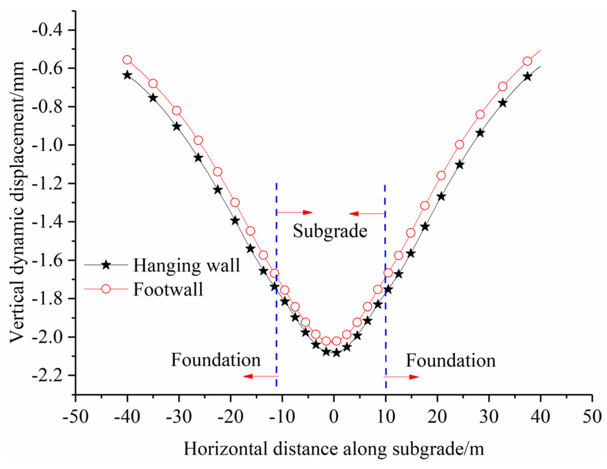
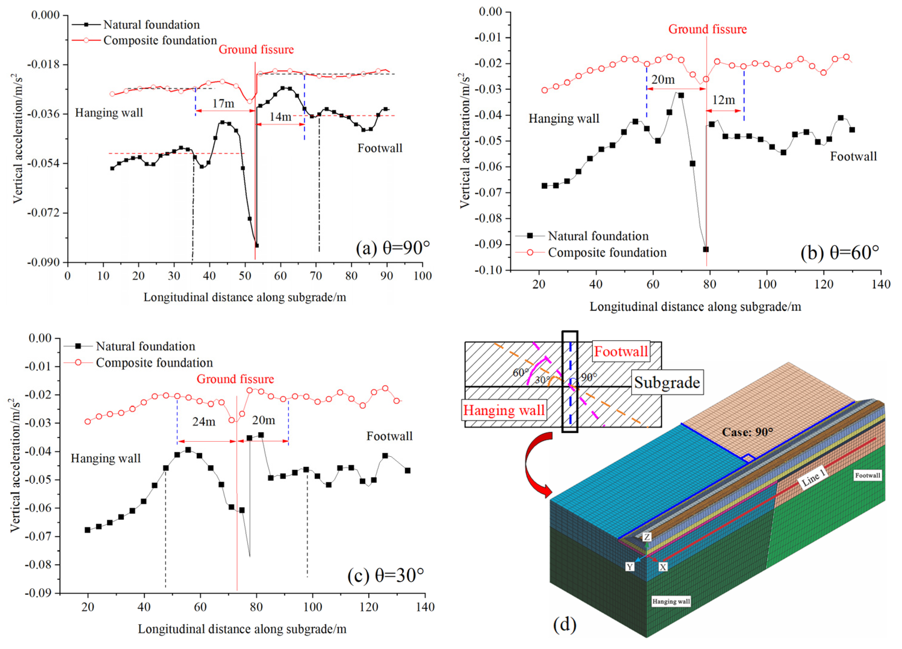
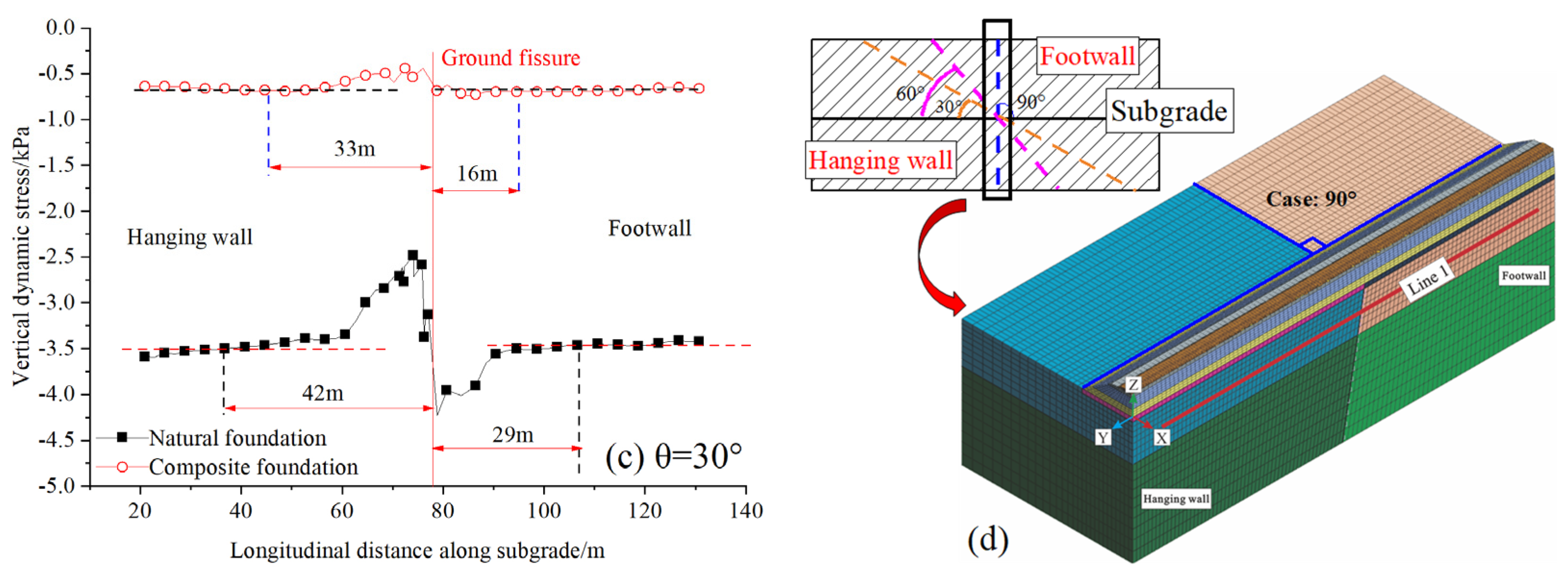
- The displacement, acceleration, and stress are basically stable at the hanging wall and footwall under the train vibration load but fluctuate at the position of the ground fissure, which specifically reflects that the displacement and acceleration increase at the hanging wall and decrease at the footwall.
- (2)
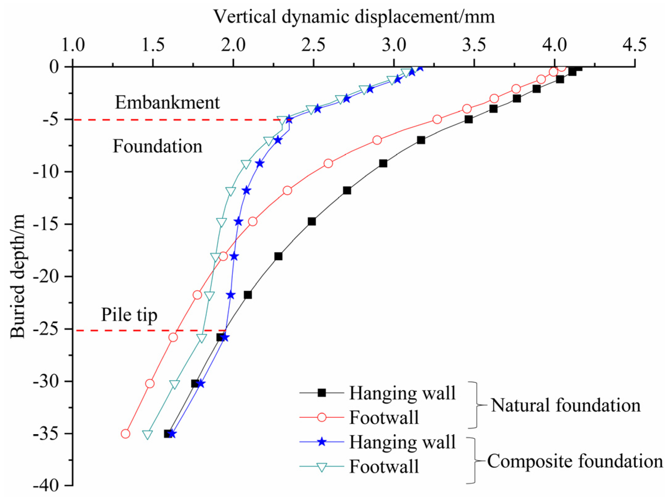
- The pile–raft structure of the composite foundation can effectively alleviate the foundation instability problem caused by the vibration load of the ground fissure site. Specifically, the side friction and axial force of the CFG pile in the hanging wall of the composite foundation are smaller than the footwall. Longitudinally, the jumping and fluctuation of displacement, acceleration, and stress in the composite foundation are weakened at the ground fissure site.
- (3)
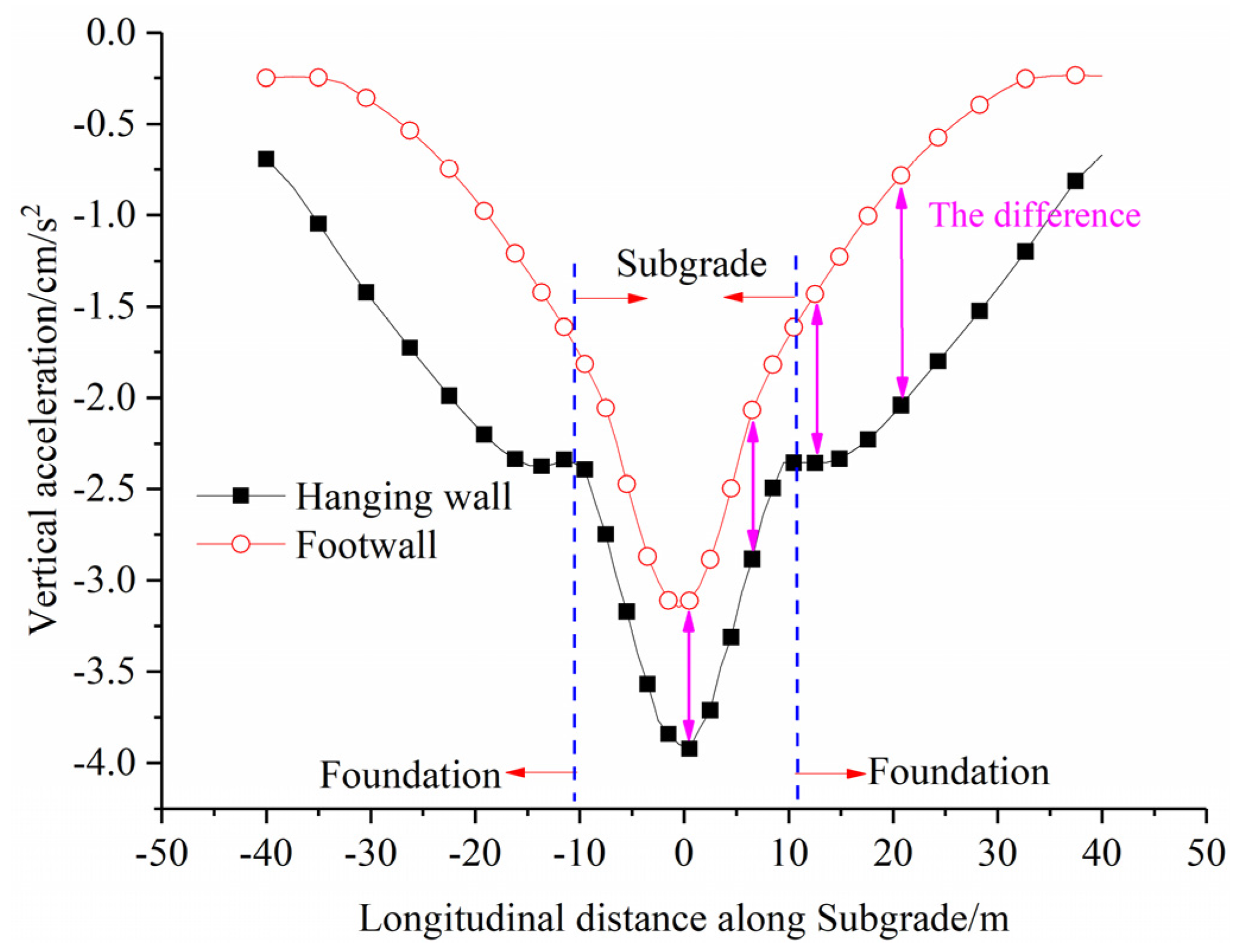
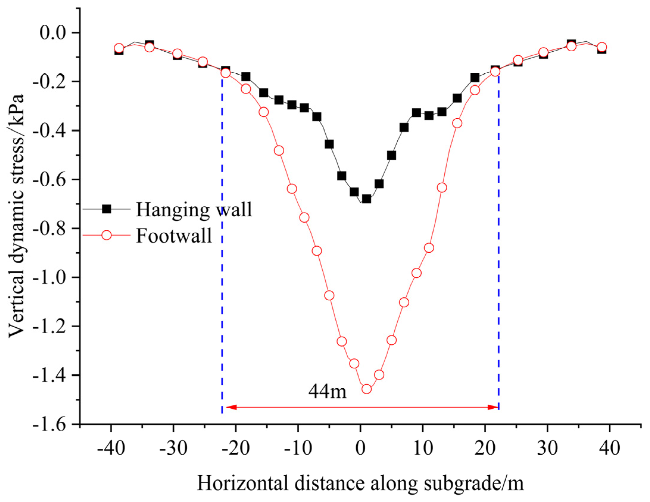
- The influence range of displacement and stress increases as the diagonal angle θ decreases. It is suggested that the high-speed railway pass through the ground fissure at a large angle when it cannot avoid the ground fissure zone. The pile length has the greatest influence on the displacement response and the dynamic stress response between the hanging wall and footwall of the ground fissure, and the concrete baseplate thickness has the greatest influence on the acceleration response of the subgrade. The risk of ground fissure disaster can be controlled by increasing the pile length.
The dynamic response of the foundation in the ground fissure site under train vibration load is very complicated. The dynamic response behavior of the Da’xi high-speed railway crossing the ground fissure zone in the Taiyuan Basin was studied using numerical simulation and orthogonal tests in this paper. The design parameters of the composite foundation in the ground fissure site were optimized. The research results provide new ideas and methods for studying the engineering stability of high-speed railways crossing the ground fissure zone worldwide. However, there are still some problems worth exploring, as follows:
The interaction mechanisms between different types of ground fissures and train vibration load are different. It is unclear what protective measures should be taken for each type of ground fissure. Therefore, based on this study, the relationship between ground fissure types and train vibration loads can be further discussed, and reasonable prevention suggestions and measures for each type of ground fissure can be provided.
Author Contributions
Q.X.: methodology, validation, and writing—review editing. Q.H.: conceptualization and funding acquisition. C.M.: validation. L.G.: validation. G.H.: methodology. All authors have read and agreed to the published version of the manuscript.
Funding
This work was supported by the National Natural Science Foundation of China (No. 41772274) and the National Key R&D Program of China (No. 2023YFC3008404).
Institutional Review Board Statement
Not applicable.
Informed Consent Statement
Not applicable.
Data Availability Statement
The raw data supporting the conclusions of this article will be made available by the authors on request.
Conflicts of Interest
Author Guohui He was employed by the company China Highway Engineering Consultants Corporation. The remaining authors declare that the research was conducted in the absence of any commercial or financial relationships that could be construed as a potential conflict of interest.
Appendix A
|
References
- Budhu, M. Earth Fissure Formation from the Mechanics of Groundwater Pumping. Int. J. Geomech. 2011, 11, 1–11. [Google Scholar] [CrossRef]
- Choubin, B.; Mosavi, A.; Alamdarloo, E.H.; Hosseini, F.S.; Shamshirband, S.; Dashtekian, K.; Ghamisi, P. Earth fissure hazard prediction using machine learning models. Environ. Res. 2019, 179, 108770. [Google Scholar] [CrossRef] [PubMed]
- Aisong, D.; Jianhua, J. Land subsidence, sinkhole collapse and earth fissure occurrence and control in China. Hydrol. Sci. J. 1994, 39, 245–256. [Google Scholar] [CrossRef]
- Eslamizadeh, A.; Samanirad, S. Land subsidence and fissuring due to ground water withdrawal in Yazd-Ardakan basin, central Iran. World Acad. Sci. Eng. Technol. 2010, 48, 489–492. [Google Scholar]
- Peng, J.; Qiao, J.; Sun, X.; Lu, Q.; Zheng, J.; Meng, Z.; Xu, J.; Wang, F.; Zhao, J. Distribution and generative mechanisms of ground fissures in China. J. Asian Earth Sci. 2020, 191, 104218. [Google Scholar] [CrossRef]
- Peng, J.B.; Xu, J.S.; Ma, R.Y.; Wang, F.Y. Characteristics and mechanism of the Longyao ground fissure on North China Plain, China. Eng. Geol. 2016, 214, 136–146. [Google Scholar] [CrossRef]
- Peng, J.B.; Sun, X.H.; Lu, Q.Z.; Meng, L.C.; He, H.Q.; Qiao, J.W.; Wang, F.Y. Characteristics and mechanisms for origin of earth fissures in Fenwei basin, China. Eng. Geol. 2020, 266, 105445. [Google Scholar] [CrossRef]
- Howard, K.W.F.; Zhou, W.F. Overview of ground fissure research in China. Environ. Earth Sci. 2019, 78, 97. [Google Scholar] [CrossRef]
- He, G.; Huang, Q.; Wang, T.; Liu, N. Numerical Analysis of Dynamic Response of High-Speed Railway Subgrade Orthogonally Crossing Ground Fissure Zone. J. Eng. Geol. 2020, 28, 149–157. [Google Scholar]
- Huang, R.Q.; Li, Y.R.; Qu, K.; Wang, K. Engineering geological assessment for route selection of railway line in geologically active area: A case study in China. J. Mt. Sci.-Engl. 2013, 10, 495–508. [Google Scholar] [CrossRef]
- Peng, J.B.; Fan, Z.J.; Liu, C.; Huang, Q.B.; Liu, J.G.; Ren, H.Y.; Wu, M.; Meng, Z.J. Experimental Analysis of a High-Speed-Railway Embankment Intersecting Steep Ground Fissures at Different Angles. Acta Geotech. Slov. 2019, 16, 13–29. [Google Scholar] [CrossRef]
- Dethy, B.; Bouhenni, S. High Speed Lines in Belgium: Various Engineering Geological and Geotechnical Aspects. In Lecture Notes in Earth Sciences; Springer: Berlin/Heidelberg, Germany, 2004. [Google Scholar]
- Peng, J.-B.; Huang, Q.-B.; Hu, Z.-P.; Wang, M.-X.; Li, T.; Men, Y.-M.; Fan, W. A proposed solution to the ground fissure encountered in urban metro construction in Xi’an, China. Tunn. Undergr. Space Technol. 2017, 61, 12–25. [Google Scholar] [CrossRef]
- Yan, Y.F.; Huang, Q.B.; Xie, Y.L.; Liu, T.; Xu, Q.; Fan, F.F.; Wang, Y.L. Failure analysis of urban open-cut utility tunnel under ground fissures environment in Xi’an, China. Eng. Fail. Anal. 2021, 127, 105529. [Google Scholar] [CrossRef]
- Peng, J.B.; He, K.; Tong, X.; Huang, Q.B.; Liu, C. Failure Mechanism of an Underground Metro Tunnel Intersecting Steep Ground Fissure at Low Angle. Int. J. Geomech. 2017, 17, E4016006. [Google Scholar] [CrossRef]
- Madshus, C.; Bessason, B.; HårvikL, L. Prediction model for low frequency vibration from high speed railways on soft ground. J. Sound Vib. 1996, 193, 195–203. [Google Scholar] [CrossRef]
- Gao, Y.; Huang, H.; Ho, C.L.; Judge, A. Field validation of a three-dimensional dynamic track-subgrade interaction model. Proc. Inst. Mech. Eng. Part F J. Rail Rapid Transit 2018, 232, 130–143. [Google Scholar] [CrossRef]
- Yang, Y.B.; Hung, H.H. A 2.5D finite/infinite element approach for modelling visco-elastic bodies subjected to moving loads. Int. J. Numer. Methods Eng. 2001, 51, 1317–1336. [Google Scholar] [CrossRef]
- Yang, Y.B.; Hung, H.H.; Chang, D.W. Train-induced wave propagation in layered soils using finite/infinite element simulation. Soil Dyn. Earthq. Eng. 2003, 23, 263–278. [Google Scholar] [CrossRef]
- Varandas, J.N.; Holscher, P.; Silva, M.A.G. Three-dimensional track-ballast interaction model for the study of a culvert transition. Soil Dyn. Earthq. Eng. 2016, 89, 116–127. [Google Scholar] [CrossRef]
- Bian, X.C.; Chao, C.; Jin, W.F.; Chen, Y.M. A 2.5D finite element approach for predicting ground vibrations generated by vertical track irregularities. J. Zhejiang Univ.-Sci. A 2011, 12, 885–894. [Google Scholar] [CrossRef]
- Ding, X.M.; Qu, L.M.; Yang, J.C.; Wang, C.L. Soil vibration induced by railway traffic around a pile under the inclined bedrock condition. Geomech. Eng. 2021, 24, 143–156. [Google Scholar] [CrossRef]
- Cheng, X.S.; Liu, G.N.; Gong, L.J.; Zhou, X.H.; Shi, B.Z. Mechanical characteristics plus differential settlement of CFG pile and cement-soil compacted pile about composite foundation under train load. Geomech. Eng. 2020, 20, 155–164. [Google Scholar] [CrossRef]
- Fu, Q.; Wu, Y. Three-dimensional finite element modelling and dynamic response analysis of track-embankment-ground system subjected to high-speed train moving loads. Geomech. Eng. 2019, 19, 241–254. [Google Scholar] [CrossRef]
- Liu, S.S.; Huang, H.; Qiu, T.; Kwon, J. Effect of geogrid on railroad ballast particle movement. Transp. Geotech. 2016, 9, 110–122. [Google Scholar] [CrossRef]
- Huang, Q.B.; Gou, Y.X.; Peng, B.; Kang, X.S.; Miao, C.Y.; Peng, J.B. Model test study on the deformation and failure mechanism of high-speed railway subgrade obliquely crossing ground fissure zones. Transp. Geotech. 2023, 41, 101182. [Google Scholar] [CrossRef]
- Vega, J.; Hermanns, L.; Alarcon, E.; Fraile, A. Measuring dynamic effects on underpasses of high-speed railway lines. Struct. Infrastruct. E 2014, 10, 41–56. [Google Scholar] [CrossRef]
- Vega, J.; Fraile, A.; Alarcon, E.; Hermanns, L. Dynamic response of underpasses for high-speed train lines. J. Sound Vib. 2012, 331, 5125–5140. [Google Scholar] [CrossRef]
- Cai, Y.; Xu, L.; Liu, W.; Shang, Y.; Su, N.; Feng, D. Field Test Study on the dynamic response of the cement-improved expansive soil subgrade of a heavy-haul railway. Soil Dyn. Earthq. Eng. 2020, 128, 105878. [Google Scholar] [CrossRef]
- Shan, Y.; Shu, Y.; Zhou, S.H. Finite-infinite element coupled analysis on the influence of material parameters on the dynamic properties of transition zones. Constr. Build. Mater. 2017, 148, 548–558. [Google Scholar] [CrossRef]
- Chen, J.; Zhou, Y. Dynamic responses of subgrade under double-line high-speed railway. Soil. Dyn. Earthq. Eng. 2018, 110, 1–12. [Google Scholar] [CrossRef]
- Ishikawa, T.; Sekine, E.; Miura, S. Cyclic deformation of granular material subjected to moving-wheel loads. Can. Geotech. J. 2011, 48, 691–703. [Google Scholar] [CrossRef]
- Zhang, C.; Jiang, G. Full-scale model testing of the dynamic response of lime-stabilized weathered red mudstone subgrade under railway excitation. Soil Dyn. Earthq. Eng. 2020, 130, 105999. [Google Scholar] [CrossRef]
- Wang, L.H.; Liu, Y.X.; Mao, L.; Sun, C. Potential Impacts of China 2030 High-Speed Rail Network on Ground Transportation Accessibility. Sustainability 2018, 10, 1270. [Google Scholar] [CrossRef]
- Peng, J.; Meng, L.; Lu, Q.; Deng, Y.; Meng, Z. Development characteristics and mechanisms of the Taigu-Qixian earth fissure group in the Taiyuan basin, China. Environ. Earth Sci. 2018, 77, 407. [Google Scholar] [CrossRef]
- Ma, L.; Liang, Q.; Gu, A.; Jiang, H. Research on Impact of Shanghai-Nanjing Intercity High-speed Railway Induced Vibration on Ambient Envi ronment and Foundation Settlement of Adjacent Beijing-Shanghai Railway. J. China Railw. Soc. 2015, 37, 98–105. [Google Scholar]
- Wang, X.; Zhang, J.; Wang, Q. Three-dimensional Numerical Simulation for Vehicle Dynamic Load and Dynamic Response of Ballastless Track Subgrade. China Earthq. Eng. J. 2014, 36, 857–867. [Google Scholar]
- Wang, F.; Xiang, B.; Xu, J.; Xu, Y.; Zhang, Q.; Che, A. Dynamic response analysis on the subgrade of the existing speed increase Jinshan railway. China Railw. Sci. 2011, 32, 13–18. [Google Scholar]
- Guo, R.; Huang, Q.B.; Zheng, B.; Liu, Z. Study on effect of piedmont fault of lishan mountain on Xi’an metro lintong line. J. Eng. Geol. 2019, 27, 682–690. [Google Scholar]
- Yan, Y.F.; Huang, Q.B.; Yang, X.J.; Wang, P. Research on the deformation and force characteristics of underground utility tunnel crossing ground fissure. J. Eng. Geol. 2018, 26, 1203–1210. [Google Scholar]
- Lysmer, J.; Kuhlmeyer, R.L. Finite Dynamic Model for Infinite Media. J. Eng. Mech. Div. 1969, 95, 859–877. [Google Scholar] [CrossRef]
- Huang, Q.; Wang, T.; Liu, Y.; He, G. Study on Dynamic Response of High-speed Railway Subgrade Crossing Ground Fissure Zone and Optimization of Foundation Reinforcement of CFG Piles. J. China Railw. Soc. 2020, 42, 103–111. [Google Scholar]
- Liu, L.; Liu, X.; Zhou, J. Numerical Analysis on Dynamic Response of The Oblique Metro Tunnel in Ground Fissure Area. J. Geomech. 2018, 24, 238–243. [Google Scholar]
- Zeng, J. Study on Influence of Groundwater in Ground Fissure Site on Dynamic Response of High-Speed Railway Subgrade. Master’s Thesis, Chang’an University, Chang’an, China, 2023. [Google Scholar]
- Feng, Q.; Sun, K.; Wang, W.; Zhang, S.; Lei, X. Optimization analysis of modern tram embedded track composite foundation. Sci. Sin. Technol. 2018, 48, 872–880. [Google Scholar] [CrossRef]
Disclaimer/Publisher’s Note: The statements, opinions and data contained in all publications are solely those of the individual author(s) and contributor(s) and not of MDPI and/or the editor(s). MDPI and/or the editor(s) disclaim responsibility for any injury to people or property resulting from any ideas, methods, instructions or products referred to in the content. |
© 2024 by the authors. Licensee MDPI, Basel, Switzerland. This article is an open access article distributed under the terms and conditions of the Creative Commons Attribution (CC BY) license (https://creativecommons.org/licenses/by/4.0/).