Article

An Ultra-Thin Composite Metasurface with Hybrid-Damping Modes for Broadband Sound Absorption

School of Mechanical Engineering, Xi’an Jiaotong University, No. 28 Xianning West Road, Xi’an 710049, China
*
Author to whom correspondence should be addressed.
Appl. Sci. 2024, 14(20), 9290; https://doi.org/10.3390/app14209290
Submission received: 3 September 2024 / Revised: 17 September 2024 / Accepted: 20 September 2024 / Published: 12 October 2024
(This article belongs to the Special Issue Novel Advances in Noise and Vibration Control)

Abstract

:
In this paper, we proposed an ultra-thin composite metasurface for broadband sound absorption, in which a compound Helmholtz structure and porous materials are coupled in a parallel-series arrangement. The Helmholtz structure comprises multiple compound cells with hybrid-damping modes, in which the over-damping and matched-damping impedance are integrated for a lower and broader absorption spectrum. By coupling the porous materials, the metasurface obtains above 85% average absorption over 750–10,000 Hz with a thickness of 31 mm, and the performance below 1600 Hz is significantly enhanced compared to the pure porous materials. This metasurface could possess broad applications in modern equipment considering its extraordinary absorption and compact structure.

1. Introduction

As modern equipment rapidly develops toward being more heavy-duty and high-speed, there exists a large amount of low-frequency broadband noise inside, but the stringent constraints on weight and thickness impose higher requirements on the absorption structures or materials. While traditional porous materials can achieve broadband absorption [1,2], they demonstrate poor efficiency for low-frequency noise. In recent years, the advancement of metamaterials and metasurfaces has presented novel solutions to tackle the low-frequency challenge [3,4,5,6,7,8,9,10,11,12,13,14,15]. However, the peak remains narrow due to the inherent limitations of resonance. Therefore, it remains a significant challenge to achieve broadband absorption from a low-frequency to high-frequency regime with compact structures.
By stimulating more absorption peaks and achieving rigorous peak couplings, the band of the current metamaterials can nearly encompass the low- and mid-frequency range below 4000 Hz [16,17,18,19,20,21,22,23,24,25,26]. However, for the equipment applications, these structures are too thick, and the band is not wide enough. To expand the band into the high-frequency region, specifically up to 10,000 Hz, the most practical approach is to couple the metamaterials with porous materials [27,28,29,30,31,32,33,34,35,36]. The composite structures can be generally divided into two categories: series or parallel arrangement. The parallel structure comprises metamaterials and porous materials arranged in parallel [27,28,29,30,31], enabling separate absorption of low- and high-frequency noise by each material. To prevent significant degradation in high-frequency absorption, it is crucial to ensure that the utilization ratio of porous materials to the whole structure remains above 70%. Owing to the limited absorption area, the metamaterials can only achieve a narrow band in the low-frequency range, thus preventing the full realization of their potential. In a series structure, the porous materials are placed in front of the metamaterial surface, and the sound waves need to pass through porous materials to reach the metamaterials [32,33,34,35,36]. To ensure continuous absorption, the porous materials must possess a specific thickness (usually above 20 mm) to achieve a lower-limit frequency that can be extended to the upper-limit frequency of the metamaterials band. However, the 20 mm-thick porous layer is highly detrimental to the design of compact structures, which can result in a larger utilization ratio exceeding 50%. If the porous layer possesses a thinner thickness, its lower-limit frequency shifts towards higher frequencies, resulting in a discontinuity in the middle of the entire frequency band. Consequently, this significant challenge needs to be solved to achieve a broader band with a thinner metamaterial. To fully leverage the low-frequency absorption advantages of the metamaterials, it is essential to reduce the utilization ratio of porous materials to mitigate their effects; otherwise, the benefits of metamaterials will be submerged or even lost.
In this work, an ultra-thin composite metasurface is introduced, in which a compound Helmholtz resonant (HR) structure and porous materials are integrated into a series-parallel connection. The HR structure comprises multiple compound cells with hybrid-damping modes, resulting in an excellent absorption spectrum that extends up to 3000 Hz. After incorporating the porous materials in series-parallel connection, the metasurface achieves about 85% average absorption across an ultra-broadband range of 750–10,000 Hz, while maintaining a thickness of just 31 mm. The utilization ratio of porous materials is reduced to about 35% for fully exploiting the low-frequency advantages of the metamaterial. Compared to the traditional porous materials, the metasurface exhibits a significant enhancement in low-frequency performance, particularly below 1600 Hz.

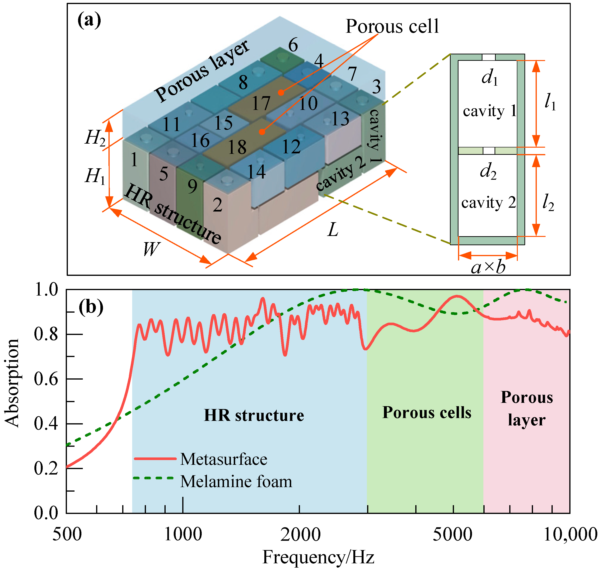
2. Broadband Absorption of the Composite Metasurface

Figure 1a demonstrates the unit of the composite metasurface, which is composed of three parts: the hybrid-damping HR structure, porous cells and the porous layer. The unit has an incident area of S0 = L × W = 70 mm × 44 mm, in which the thickness of the porous layer and the HR structure are H1 = 10 mm and H2 = 21 mm, respectively. The HR structure is composed of 16 cells, in which cells 1–8 are compound HRs composed of two cavities, and cells 9–16 are single-cavity ones. The longer compound HR cells are folded and extended beneath the shorter single-cavity cells, effectively reducing the overall thickness of the structure. It is worth noting that the cell absorption performance mainly depends on the cavity volumes, so it can be flexibly arranged, such as horizontally or vertically. The porous cells 17 and 18 with length l = 25 mm and width w = 10 mm are arranged in parallel with the HR structures, of which the heights are h1 = 20 mm and h2 = 12 mm. The melamine foam is selected as the base material for the porous cells and the porous layer, but the basic parameters are not completely consistent and will be given in later discussions. The absorption coefficient of the metasurface is presented in Figure 1b and compared with that of pure melamine foam with the same thickness. It can be observed that the metasurface obtains an ultra-broadband absorption spectrum over 750–10,000 Hz with an average absorption above 85%. Compared with pure melamine foam, the low-frequency average absorption coefficient is significantly enhanced from 60% to nearly 83% below 1600 Hz. The broadband HR structure plays a dominant role in the spectrum below 3000 Hz, and with the incorporation of porous cells, the absorption range is expanded to 6000 Hz. Finally, it extends further to 10,000 Hz by adding the porous layer, effectively achieving broadband absorption spanning from a low- to high-frequency range with an ultra-thin structure. However, it is unfortunate that owing to the utilization of fewer porous materials, the metasurface cannot achieve the same excellent absorption performance above 1.5 kHz as the melamine foam with the same thickness.

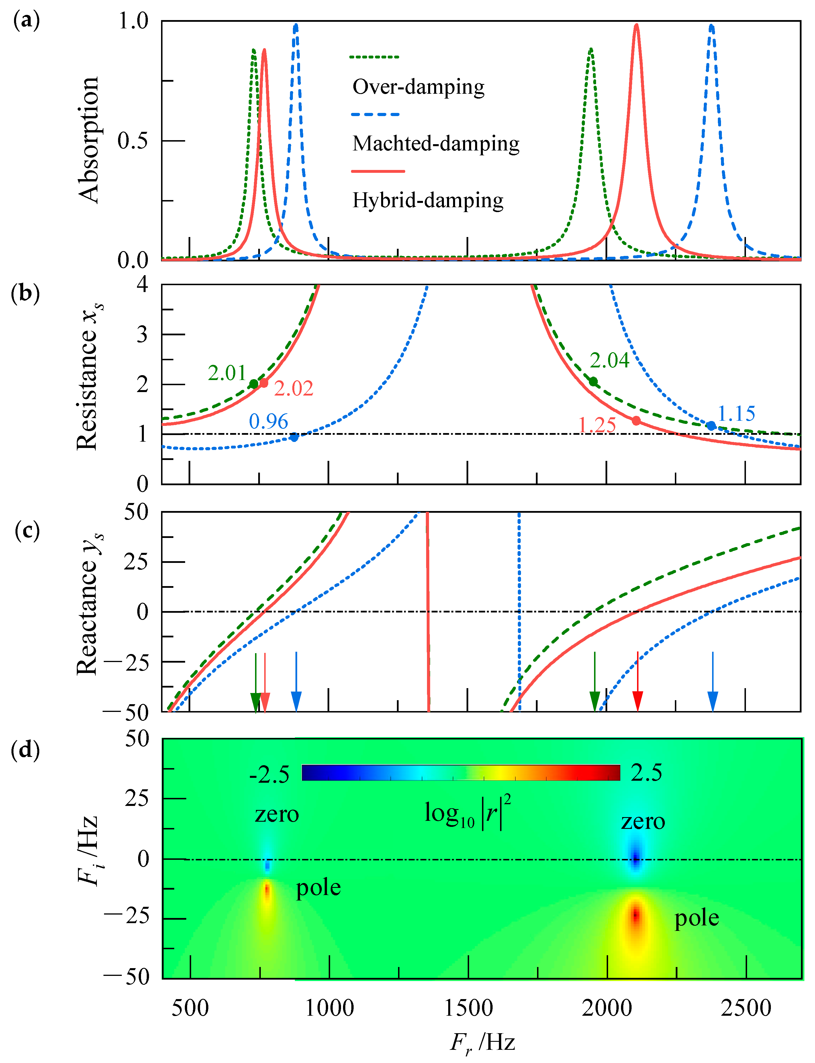
3. Compound HR Structure with Hybrid-Damping Modes

3.1. Structure of the Broadband Unit and Cell

As depicted in Figure 1a, the broadband HR structure incorporates eight compound HR cells to expand the absorption band, enabling the acquisition of high-order peaks with the external dimensions unchanged [20]. For an absorption cell, its relative specific impedance can be expressed as zs = Zs/ρ0c0 = xs + jys, where Zs is the surface specific impedance, ρ0c0 is the characteristic impedance of air, and xs, ys are the relative specific resistance and relative specific reactance, respectively. With ys = 0, the cell is in the resonance state and gains an absorption peak, and on this basis, the perfect absorption can be achieved with xs = 1. This impedance is called matched-damping impedance, and it will turn into over-damping and under-damping impedance when xs > 1 and xs < 1, respectively, both of which can result in a reduction in the peaks. In the case of over-damping cells, the peaks are all equipped with over-damping impedance and can obtain imperfect absorption. Furthermore, in a hybrid-damping cell, the peaks simultaneously exhibit over-damping and matched-damping impedance.
Figure 2a illustrates the sound absorption performances of the compound cells with various damping modes. The cell cavity lengths are l1 = 26 mm and l2 = 28 mm, and the cross-section area is a × b = 10 mm × 10 mm. For the matched-damping, over-damping and hybrid-damping cells, the hole diameters are d1 = 4.8 mm, 3.3 mm, 4.5 mm, and d2 = 2.3 mm, 1.7 mm, 1.7 mm, respectively. It can be observed that the results of the matched-damping cell achieve two nearly perfect absorption peaks at f1 = 900 Hz and f2 = 2480 Hz. According to the impedance-matched conditions, both peaks obtain impedances that are matched with that of air, i.e., the relative specific resistances xs ≈ 1, as shown Figure 2b,c. Owing to the decrease in the hole diameters, the acoustic resistances of the two peaks are increased to xs ≈ 2, resulting in a 10% decrement in the absorption coefficients. Furthermore, the peaks have shifted to f1 = 745 Hz and f2 = 1990 Hz attributed to the increased acoustic masses. In the hybrid-damping cell, the acoustic resistances for the two peaks are xs1 = 2.02 and xs2 = 1.25, so the first peak still maintains excellent low-frequency performance despite a minor deviation towards higher frequencies, whereas the second peak achieves almost 100% absorption.
Figure 2d presents the complex frequency plane representation of the hybrid-damping cell. The reflection coefficient can be plotted on the complex frequency plane by replacing the frequency as f’ = fr + jfi, where fr is the intrinsic frequency and fi is the imaginary frequency. The reflection coefficient, therefore, exhibits a complex conjugate zero and pole in a lossless system. As the loss is incorporated into the system, the zero and pole will be shifted down along the imaginary axis. When the zero is located on the real frequency axis, the intrinsic losses perfectly balance the energy leakage, resulting in perfect absorption, which is called the critical coupling condition. It can be seen that the first zero of the hybrid-damping cell is located beneath the real axis, indicating the over-damping mode of the peak, while the second zero falls on the real axis, attributed to the matched-damping impedance, thereby facilitating perfect absorption. Furthermore, the second peak exhibits a more significant leakage rate (distance) between the zero and pole, which can contribute to a wider bandwidth.
By coupling multiple over-damping peaks, the broadband absorption band can be obtained within the lower-frequency range, even achieving perfect absorption once again, which has been an effective method to reduce the structure thickness [21,23]. However, in order to fully utilize the coupling effect, the over-damping peaks impose stringent requirements on peak frequency, making it challenging to simultaneously adjust both the first and high-order peaks to their target positions. On this basis, the absorption performance can be significantly enhanced by the adoption of hybrid-damping modes, which exhibit a superiority in low-frequency broadband absorption by integrating the benefits of over-damping and matched-damping modes.

3.2. Calculation of Sound Absorption Coefficient

3.2.1. Theoretical Calculation

As a typical multiple-layer structure, the acoustic impedance of the cell in Figure 1a can be derived with the impedance transfer matrix of each layer. Each layer is composed of a circular hole di and an air cavity with length li and cross-sectional area Sc = a × b.
The specific impedance Zhi of the small hole can be expressed as [1]
Z h i = j ω ρ 0 σ i { t i [ 1 2 B 1 ( χ j ) ( χ j ) B 0 ( χ j ) ] 1 + Δ t } + 2 μ χ σ i d i
where j = 1 is the imaginary unit, σi = Shi/Sc is the area ratio of the small hole to the cavity, Shi is the area of the small hole, µ is the dynamic viscosity coefficient, and Δt is the impedance correction at the hole end, which is composed of two parts as Δti = Δt1 + Δt2. The first length correction Δt1 is caused by the pressure radiation at the discontinuity when the small hole radiates to the cavity, and the second one Δt2 comes from the radiation at the discontinuity from the small hole to the upper waveguide.
Δ t 1 = 0.41 [ 1 1.35 d i d c + 0.31 ( d i d c ) 3 ] d i
Δ t 2 = 0.41 [ 1 0.235 d i d n 1.32 ( d i d n ) 2 + 1.54 ( d i d n ) 3 0.86 ( d i d n ) 4 ] d i
where d c = 2 S c / π is the cavity equivalent diameter and d n = 2 S 0 / π is the equivalent diameter of the external waveguide.
The effective propagation wave numbers and characteristic impedance of the cavity are k i e = ω ρ i e c i e and Z i e = ρ i e / c i e , where ρ i e and c i e can be obtained by thermal viscous acoustics theory as
ρ i e = ρ 0 ν a 2 b 2 4 j ω { m = 0 n = 0 [ α m 2 β n 2 ( α m 2 + β n 2 + j ω ν ) ] 1 } 1
c i e = 1 P 0 { 1 4 j ω ( γ 1 ) ν a 2 b 2 m = 0 n = 0 [ α m 2 β n 2 ( α m 2 + β n 2 + j ω γ ν ) ] 1 }
where αm = (m + 1/2)π/a and βn = (n + 1/2)π/a, ν = μ/ρ0 and ν’ = κ/(ρ0Cv), with κ and Cv representing the thermal conductivity and specific heat at a constant volume, respectively. P0 = 101.325 kPa and γ = 1.4 are the air pressure and the ratio of specific heat.
The impedance transfer matrix of the small hole and the air cavity are then
T h i = [ 1 Z h i 0 1 ]
T c i = [ 1 j Z i e tan k i e l i j tan k i e l i / Z i e 1 ]
The sound pressure p1 and the mass velocity v1 on the cell surface are hence
[ p 1 v 1 ] = T h 1 T c 1 T h 2 T c 2 [ p e 0 ]
where pe is the sound pressure of the cavity bottom, and the corresponding mass velocity is zero. As a result, the specific surface impedance and the absorption coefficient of the cell are obtained as
Z a = 1 S c p 1 v 1
α = 1 | Z a ρ 0 c 0 Z a + ρ 0 c 0 | 2
where ρ0 = 1.25 kg/m3 and c0 = 343 m/s are the density and the sound velocity of air.

3.2.2. Finite Element Simulation

The numerical simulation is developed by using the commercial FEM package COMSOL MultiphysicsTM 6.0, in which the Pressure Acoustics module is adopted. The schematic diagram of the finite element model is illustrated in Figure 3. The domain of Narrow Region Acoustics is employed to characterize the viscous and thermal dissipation in the small holes and cavities, while the air before the unit is defined as the Pressure Acoustics domain. Since different losses of air medium are introduced in a homogenized way, this method requires less computational resources and can significantly improve efficiency compared with the Acoustic–Thermoacoustic module. The small holes employ the circular hole model, while the cavity utilizes the wide tube model. Due to the much larger impedance than that of air, hard boundaries are applied for all the cell cavity walls. The Floquet conditions are chosen on both sides of the metasurface unit for the periodic arrangement. A normal incident plane wave with unit amplitude is applied on the structure surface. The maximum size of the meshes for the cavity and holes is lower than 1/8 of the shortest incident wavelength, while the minimum mesh in the holes is of dv/2, where d v = 2 μ / ω ρ 0 is the viscous boundary-layer thickness. The absorption coefficient is obtained as α = 1 | r | 2 , where r is the complex reflection coefficient of the average sound pressure over the incident boundary.

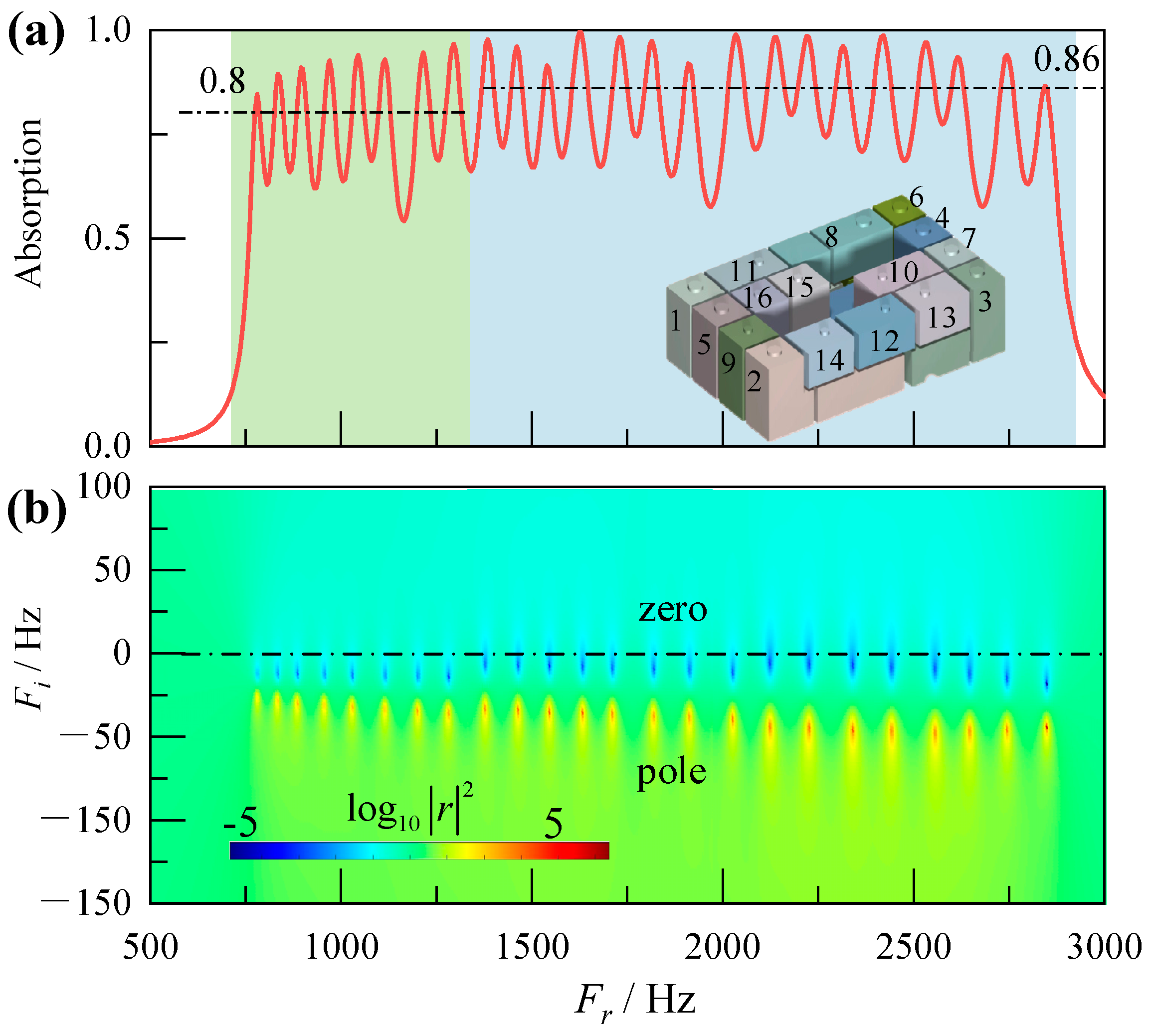
3.3. Broadband Absorption of Hybrid-Damping Unit

For broadband continuous absorption, a hybrid-damping HR structure, composed of 16 detuned cells, is designed with a thickness of only 21 mm. As shown in Figure 4a, the cells 1–8 are the hybrid-damping compound cells, of which the peak frequency can be adjusted by the cavity depth l1 and l2. The cells 9–16 are the single-cavity ones used to fill the valley of the spectrum of the compound cells. The hole diameters of the compound cells are d1 = 4 mm and d2 = 1.7 mm, while that of single-cavity cells is d0 = 2.2 mm. Most cells have a cavity cross-section of a × b = 10 mm × 10 mm, and to ensure optimal utilization of space, minor adjustments are made to the cross section of certain cells. The length of the cells has a large span from l1 = 54 mm to l16 = 10 mm.
The absorption coefficient of the HR structure is presented in Figure 4a, from which it can be observed that it obtains excellent performance in the range of 750–2900 Hz. Owing to the over-damping impedance, the first part of the band (green area), composed of the first peaks of cells 1–8, is extended to the low-frequency regime with the maximum and average absorption of 90% and 80%, respectively. The second part (blue area) can achieve 86% average absorption due to the weaker impedance, which includes the peaks of cells 9–16 and the second peaks of cells 1–8. As depicted in Figure 4b, it is evident that the first eight zeros are located below the real axis due to the over-damping impedance, while the remaining zeros are distributed near the real frequency axis, indicating higher absorption abilities. It should be noted that the absorption band exceeds nearly 3 octaves with a thickness of only 21 mm, 1/22 of the wavelength at f = 750 Hz, demonstrating the advantages of this ultra-thin structure in low-frequency broadband absorption and the significant engineering application potentials.

4. Band Expansion through Porous Materials

4.1. Porous Materials Arranged in Parallel

To further expand the band to high-frequency region, a composite structure has been designed, in which the melamine foams, as porous cells, are filled into the groove of the HR structure. When the foams are arranged in parallel with HR structures, the whole absorption band can be significantly broadened without any increase in structure thickness. Nevertheless, as a single cell in the broadband structure, the sound absorption performance of the foam undergoes considerable variations because the area of the foam is smaller than the incident area of the whole structure. The area ratio of the porous cell to the structure is defined as η = Sc/S0 with Sc = l × w, and the specific relative resistance of the porous cell is, therefore, xs = xs0/η, where xs0 is the inherent resistance of the melamine foam. Figure 5a demonstrates the absorption performance of the porous cell with different area ratios. The foam thickness is set as h = 20 mm, while the key parameters include the porosity ϕ = 0.95, tortuous factor   α = 1.07, flow resistance σ = 11,660 Pa·s/m2, viscous characteristic length Λ = 78.2 μm, and the thermal characteristic length Λ’ = 155.3 μm. It can be seen that as the area ratio gradually decreases, the peak of the porous cell becomes narrow. Especially when the area ratio is η = 1/9 and 1/12, its absorption performance closely resembles that of resonant structures, nearly losing its broadband characteristics. On the other hand, the decreased area ratio will result in an increase in the cell’s specific resistance. When the specific resistance increases to be matchable with that of air, the peak can approximately achieve 100% absorption with the area ratio of η = 1/4. As the area ratio continues to decrease, the peak gradually diminishes due to the increased resistance.
Therefore, the foam requires a lower flow resistance for excellent absorption with a decreased area ratio. Based on the above analysis, the thicknesses of the two porous cells have been chosen to be h1 = 20 mm and h2 = 12 mm, respectively. Figure 5b shows the absorption coefficients of the composite structure, HR structure and the porous cells. It can be seen that the two cells exhibit two peaks near 3500 Hz and 5500 Hz, with absorption coefficients approximating 71% and 82%, respectively. By incorporating porous cells, the absorption band is significantly broadened from 3000 Hz to 6000 Hz, while the absorption performance of the original HR structure remains almost unaffected. This remarkable ultra-broadband absorption performance alleviates the stringent requirements for the upper porous layer, so its thickness can be reduced as much as possible.

4.2. Porous Materials Arranged in Series

In order to further improve the absorption performance beyond 6000 Hz, a composite metasurface is obtained by placing a melamine foam, as a porous layer, on the structure’s surface. Given that the layer’s area corresponds exactly to the incident area, i.e., η = 1, its acoustic resistance can be incrementally enhanced to optimize the absorption performance for the high-frequency sounds. As depicted in Figure 6a, the influences on the sound absorption performance of the foam thickness are first pronounced. The parameters of the foam here are different from those of the porous cells, which are the porosity ϕ = 0.97, tortuous factor   α = 1.02, flow resistance σ = 19,780 Pa·s/m2, viscous characteristic length Λ = 90.3 μm, and the thermal characteristic length Λ’ = 178.5 μm. As the thickness increases, the absorption coefficient experiences a notable enhancement, accompanied by a gradual shift in the peak frequency towards lower frequencies. At a thickness of 10 mm, the foam exhibits an average absorption of 80% in the frequency range above 6000 Hz. However, when the thickness is 20 mm, although the absorption performance is enhanced, its thickness is almost the same as that of the HR structure. This doubles the thickness of the structure, which is not desirable.
The foam with a thickness of 10 mm is, therefore, adopted as the porous layer. As shown in Figure 6b, the metasurface achieved an average absorption over 85% across the frequency range of 750–10,000 Hz. The low-frequency sound can penetrate the porous layer and be absorbed by the HR structure behind it. Owing to the additional resistance of the porous layer, the overall resistance of the metasurface is augmented, leading to a decrease in the absorption peaks and a smoother absorption spectrum. When the high-frequency sound waves strike the metasurface, the HR structure loses the absorption ability and functions as a rigid wall, which reflects all incoming sound waves. Consequently, the sound wave is absorbed by the porous layer, thus maintaining its original absorption performance.

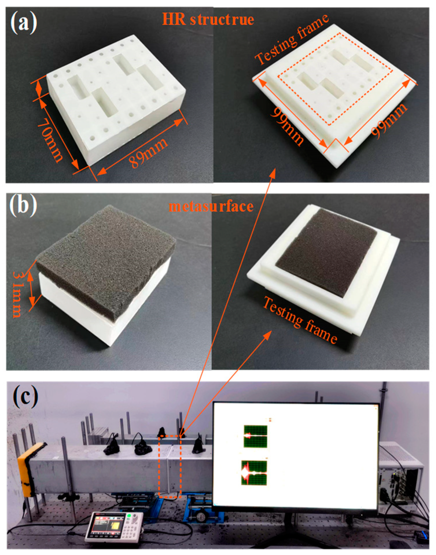
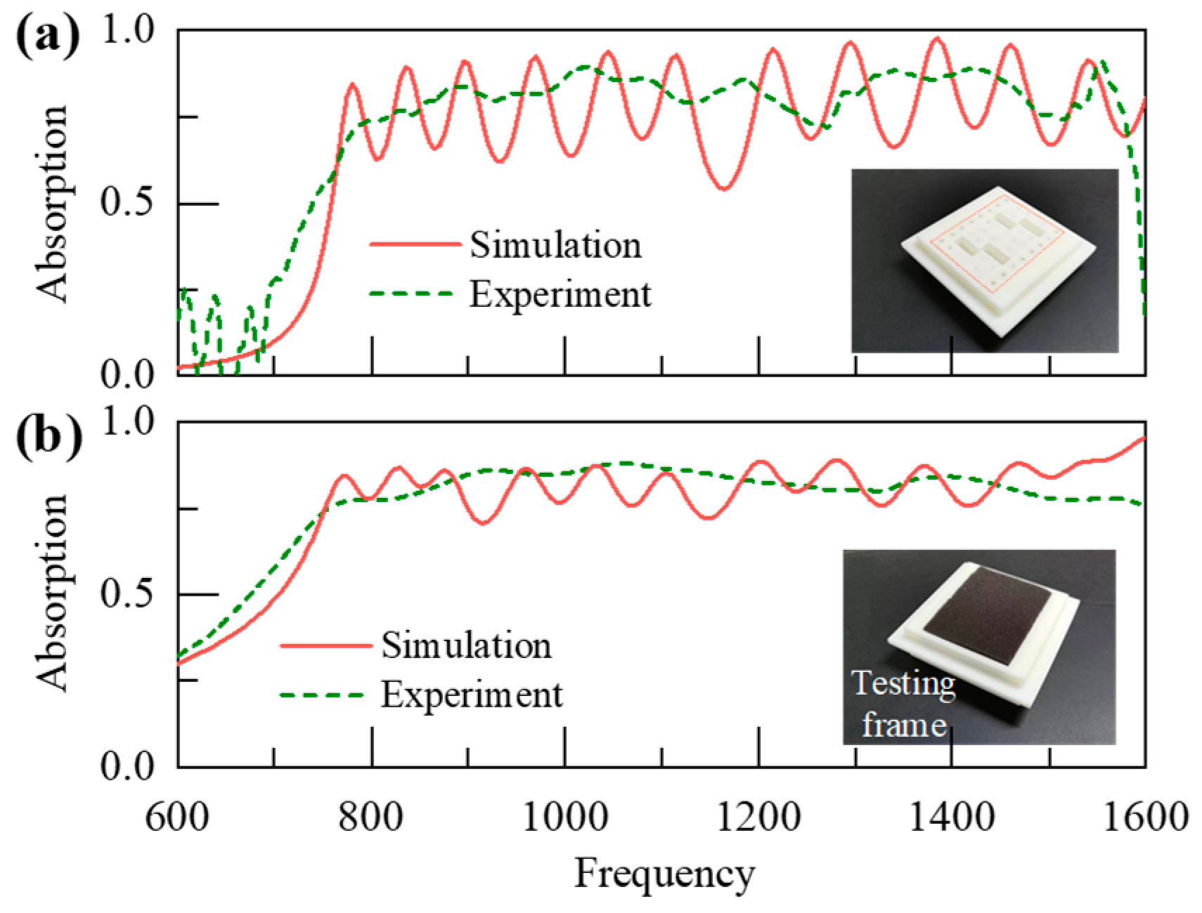
5. Experiment Validation

The samples of the HR structure were fabricated by 3D printing technology with ABS plastic, as shown in Figure 7a. The sample is composed of two basic units, as shown in Figure 1a, and has a dimension of 89 mm × 70 mm × 21 mm. The metasurface sample is achieved by placing the foams inside the HR structure. The impedance tube has a side length of 100 mm, in which only the plane wave can propagate below 1600 Hz, by which the test frequency range is limited and cannot cover the whole target band here. Due to the smaller size of the sample area compared to the tube area, the sample is positioned within a testing frame to fill the gap between the tube and the sample. The assembly’s incident surface is kept flat, and the surrounding area of the sample is ensured as a rigid wall. Consequently, the sample’s specific surface impedance can be obtained, and the sound absorption coefficient is calculated accordingly. To ensure that the foam remains firmly in the metasurface sample during the testing process, it has been adhered to the frame using glue applied along its perimeter.
The experimental results of the HR structure and metasurface are shown in Figure 8a,b. It can be observed that the HR structure obtains a smoother spectrum with 82% average absorption in the experimental result, while 78% average absorption is achieved in the simulation result but with obvious fluctuations. This error of absorption performance can mainly be attributed to the manufacturing errors of small hole diameters and the energy dissipation of air itself. Considering that the precision of 3D printing technology is ±0.1 mm, the sample may obtain smaller holes with stronger damping, by which the absorption can be enhanced. Furthermore, owing to the inherent viscosity, the air medium itself can still cause some attenuation during the propagation of sound waves, which can broaden the peak bandwidth and lead to a smoother spectrum. In Figure 8b, with the assistance of the porous layer, the metasurface achieves a much flatter absorption spectrum. Both experimental and simulation results exhibit 81% average sound absorption, albeit with minor fluctuations observed solely in the simulation results. The absorption fluctuations are further suppressed by incorporating the porous layer. It is evident that the experimental results can verify the effectiveness of simulation works, so the predicted absorption performance is also credible across the range of 1600–10,000 Hz.

6. Conclusions

In this study, we introduced an ultra-thin acoustic composite metasurface, which can achieve above 85% continuous absorption of over 750–10,000 Hz with a thickness of 31 mm. A 20 mm-thick compound HR structure was first designed with the hybrid-damping modes, by which the band was broadened by about 70% and the high-order peaks were optimized to obtain 100% absorption. This advancement serves as a solid foundation for the achievement of compact metasurfaces. By gradually incorporating the parallel porous cells and series layer, the absorption spectrum can be expanded to 10,000 Hz. Compared to the porous foams of the same thickness, the performance of this metasurface is obviously improved below 1600 Hz. The utilization ratio of porous materials in this structure has been significantly reduced to about 35%, allowing the low-frequency advantages of the metamaterial to be fully exploited. The metasurface would offer a new approach to obtain ultra-broadband absorption with a thin structure and show great potential in modern equipment.

Author Contributions

Conceptualization, C.L.; Methodology, C.L.; Software, Z.X.; Validation, Z.X.; Formal analysis, X.L.; Writing—original draft, C.L.; Writing—review & editing, X.L.; Supervision, C.L.; Funding acquisition, C.L. All authors have read and agreed to the published version of the manuscript.

Funding

This work was supported by the Aeronautical Science Foundation of China under Grant No. 20220015070001, the National Natural Science Foundation of China (NSFC) under Grant No. 52105120, and the China Postdoctoral Science Foundation under Grant No. 2021M692552.

Institutional Review Board Statement

Not applicable.

Informed Consent Statement

Not applicable.

Data Availability Statement

The original contributions presented in the study are included in the article, further inquiries can be directed to the corresponding author.

Conflicts of Interest

The authors declare no conflict of interest.

References

  1. Arenas, J.P.; Crocker, M.J. Recent Trends in Porous Sound-Absorbing Materials. Sound Vib. 2010, 44, 12–18. [Google Scholar]
  2. Cao, L.; Fu, Q.; Si, Y.; Ding, B.; Yu, J. Porous Materials for Sound Absorption. Compos. Commun. 2018, 10, 25–35. [Google Scholar] [CrossRef]
  3. Assouar, B.; Liang, B.; Wu, Y.; Li, Y.; Cheng, J.C.; Jing, Y. Acoustic Metasurfaces. Nat. Rev. Mater. 2018, 3, 460–472. [Google Scholar] [CrossRef]
  4. Yang, M.; Sheng, P. Sound Absorption Structures: From Porous Media to Acoustic Metamaterials. Annu. Rev. Mater. Res. 2017, 47, 83–114. [Google Scholar] [CrossRef]
  5. Palma, G.; Mao, H.; Burghignoli, L.; Göransson, P.; Iemma, U. Acoustic Metamaterials in Aeronautics. Appl. Sci. 2018, 8, 971. [Google Scholar] [CrossRef]
  6. Mei, J.; Ma, G.; Yang, M.; Yang, Z.; Wen, W.; Sheng, P. Dark Acoustic Metamaterials as Super Absorbers for Low-Frequency Sound. Nat. Commun. 2012, 3, 756–757. [Google Scholar] [CrossRef] [PubMed]
  7. Li, J.; Wang, W.; Xie, Y.; Popa, B.I.; Cummer, S.A. A Sound Absorbing Metasurface with Coupled Resonators. Appl. Phys. Lett. 2016, 109, 091908. [Google Scholar] [CrossRef]
  8. Lee, T.; Iizuka, H. Heavily Overdamped Resonance Structurally Engineered in a Grating Metasurface for Ultra-Broadband Acoustic Absorption. Appl. Phys. Lett. 2018, 113, 101903. [Google Scholar] [CrossRef]
  9. Li, Y.; Assouar, B.M. Acoustic Metasurface-Based Perfect Absorber with Deep Subwavelength Thickness. Appl. Phys. Lett. 2016, 108, 063502. [Google Scholar] [CrossRef]
  10. Zhou, J.; Zhang, X.; Fang, Y. Three-Dimensional Acoustic Characteristic Study of Porous Metasurface. Compos. Struct. 2017, 176, 1005–1012. [Google Scholar] [CrossRef]
  11. Ma, F.; Wang, C.; Du, Y.; Zhu, Z.; Wu, J.H. Enhancing of Broadband Sound Absorption through Soft Matter. Mater. Horizons 2022, 9, 653–662. [Google Scholar] [CrossRef] [PubMed]
  12. Jiménez, N.; Huang, W.; Romero-García, V.; Pagneux, V.; Groby, J.P. Ultra-Thin Metamaterial for Perfect and Quasi-Omnidirectional Sound Absorption. Appl. Phys. Lett. 2016, 109, 121902. [Google Scholar] [CrossRef]
  13. Kumar, S.; Lee, H.P. Labyrinthine Acoustic Metastructures Enabling Broadband Sound Absorption and Ventilation. Appl. Phys. Lett. 2020, 116, 134103. [Google Scholar] [CrossRef]
  14. Dupont, T.; Leclaire, P.; Panneton, R.; Umnova, O. A Microstructure Material Design for Low Frequency Sound Absorption. Appl. Acoust. 2018, 136, 86–93. [Google Scholar] [CrossRef]
  15. Mahesh, K.; Kumar Ranjith, S.; Mini, R.S. Inverse Design of a Helmholtz Resonator Based Low-Frequency Acoustic Absorber Using Deep Neural Network. J. Appl. Phys. 2021, 129, 174901. [Google Scholar] [CrossRef]
  16. Huang, S.; Zhou, Z.; Li, D.; Liu, T.; Wang, X.; Zhu, J.; Li, Y. Compact Broadband Acoustic Sink with Coherently Coupled Weak. Sci. Bull. 2019, 65, 373–379. [Google Scholar] [CrossRef]
  17. Liu, C.R.; Wu, J.H.; Yang, Z.; Ma, F. Ultra-Broadband Acoustic Absorption of a Thin Microperforated Panel Metamaterial with Multi-Order Resonance. Compos. Struct. 2020, 246, 112366. [Google Scholar] [CrossRef]
  18. Jiménez, N.; Romero-García, V.; Pagneux, V.; Groby, J.P. Rainbow-Trapping Absorbers: Broadband, Perfect and Asymmetric Sound Absorption by Subwavelength Panels for Transmission Problems. Sci. Rep. 2017, 7, 13595. [Google Scholar] [CrossRef] [PubMed]
  19. Peng, X.; Ji, J.; Jing, Y. Composite Honeycomb Metasurface Panel for Broadband Sound Absorption. J. Acoust. Soc. Am. 2018, 144, EL255–EL261. [Google Scholar] [CrossRef]
  20. Liu, C.R.; Wu, J.H.; Chen, X.; Ma, F. A Thin Low-Frequency Broadband Metasurface with Multi-Order Sound Absorption. J. Phys. D Appl. Phys. 2019, 52, 105302. [Google Scholar] [CrossRef]
  21. Liu, Y.; Ren, S.; Sun, W.; Lei, Y.; Wang, H.; Zeng, X. Broadband Low-Frequency Sound Absorbing Metastructures Based on Impedance Matching Coiled-up Cavity. Appl. Phys. Lett. 2021, 119, 101901. [Google Scholar] [CrossRef]
  22. Ryoo, H.; Jeon, W. Broadband Sound Absorption Using Multiple Hybrid Resonances of Acoustic Metasurfaces. Int. J. Mech. Sci. 2022, 229, 107508. [Google Scholar] [CrossRef]
  23. Liu, C.; Yang, Z.; Liu, X.; Wu, J.H.; Ma, F. Ultra-Broadband Acoustic Absorption with Inhomogeneous High-Order Fabry-Pérot Resonances. APL Mater. 2023, 11, 101122. [Google Scholar] [CrossRef]
  24. Shao, C.; Zhu, Y.; Long, H.; Liu, C.; Cheng, Y.; Liu, X. Metasurface Absorber for Ultra-Broadband Sound via over-Damped Modes Coupling. Appl. Phys. Lett. 2022, 120, 083504. [Google Scholar] [CrossRef]
  25. Mei, Z.; Li, X.; Lyu, Y.; Sang, J.; Cheng, X.; Yang, J. Broadband Sound Absorption Based on Impedance Decoupling and Modulation Mechanisms. J. Acoust. Soc. Am. 2023, 154, 3479–3486. [Google Scholar] [CrossRef]
  26. Zhou, Z.; Huang, S.; Li, D.; Zhu, J.; Li, Y. Broadband Impedance Modulation via Non-Local Acoustic Metamaterials. Natl. Sci. Rev. 2022, 9, nwab171. [Google Scholar] [CrossRef]
  27. Yang, J.; Lee, J.S.; Kim, Y.Y. Multiple Slow Waves in Metaporous Layers for Broadband Sound Absorption. J. Phys. D Appl. Phys. 2017, 50, 015301. [Google Scholar] [CrossRef]
  28. Zhu, X.F.; Lau, S.K.; Lu, Z.; Jeon, W. Broadband Low-Frequency Sound Absorption by Periodic Metamaterial Resonators Embedded in a Porous Layer. J. Sound Vib. 2019, 461, 114922. [Google Scholar] [CrossRef]
  29. Yuan, T.; Song, X.; Xu, J.; Pan, B.; Sui, D.; Xiao, H.; Zhou, J. Tunable Acoustic Composite Metasurface Based Porous Material for Broadband Sound Absorption. Compos. Struct. 2022, 298, 116014. [Google Scholar] [CrossRef]
  30. Zhao, H.; Wang, Y.; Yu, D.; Yang, H.; Zhong, J.; Wu, F.; Wen, J. A Double Porosity Material for Low Frequency Sound Absorption. Compos. Struct. 2020, 239, 111978. [Google Scholar] [CrossRef]
  31. Li, Y.; Lin, Y.; Yao, S.; Shi, C. Low-Frequency Broadband Sound Absorption of the Metastructure with Extended Tube Resonators and Porous Materials. Appl. Acoust. 2024, 217, 109827. [Google Scholar] [CrossRef]
  32. Yang, M.; Chen, S.; Fu, C.; Sheng, P. Optimal Sound-Absorbing Structures. Mater. Horizons 2017, 4, 673–680. [Google Scholar] [CrossRef]
  33. Long, H.; Shao, C.; Liu, C.; Cheng, Y.; Liu, X. Broadband Near-Perfect Absorption of Low-Frequency Sound by Subwavelength Metasurface. Appl. Phys. Lett. 2019, 115, 1–12. [Google Scholar] [CrossRef]
  34. Xie, S.; Li, Z.; Yan, H.; Yang, S. Ultra-Broadband Sound Absorption Performance of a Multi-Cavity Composite Structure Filled with Polyurethane. Appl. Acoust. 2022, 189, 108612. [Google Scholar] [CrossRef]
  35. Yan, J.; Li, Y.; Peng, Y.; Yao, S. Acoustic Metasurface Embedded with Thin-Walled Plate Based on Phase Modulation for Multi-Angle Broadband Sound Absorption. Thin-Walled Struct. 2024, 199, 111839. [Google Scholar] [CrossRef]
  36. Cheng, B.; Gao, N.; Huang, Y.; Hou, H. Broadening Perfect Sound Absorption by Composite Absorber Filled with Porous Material at Low Frequency. J. Vib. Control 2022, 28, 410–424. [Google Scholar] [CrossRef]
Figure 1. (a) Basic unit of the metasurface composed of an HR structure, two porous cells and a porous layer. The unit has an incident area S0 = L × W = 68 mm × 44 mm, and the thickness of the porous layer and the HR structure are H1 = 10 mm and H2 = 21 mm, respectively. The numbers from 1 to 16 denote the cells with first-order peak frequency from lower to higher. The cells 17 and 18 are the porous cells. (b) The sound absorption coefficients of the metasurface and the melamine foam with the same thickness.
Applsci 14 09290 g001
Figure 2. (a) Sound absorption coefficients, (b) relative specific resistance and (c) relative specific reactance of the compound cell with different damping modes. The arrows represent the peak frequencies and the reactance zeros of the compound cells. (d) The complex frequency plane representation of the hybrid-damping cell.
Applsci 14 09290 g002
Figure 3. The schematic diagram of the finite element model for the metasurface unit.
Applsci 14 09290 g003
Figure 4. (a) Sound absorption coefficients and (b) the complex frequency plane representation of the broadband HR structure with hybrid-damping modes.
Applsci 14 09290 g004
Figure 5. Sound absorption coefficients of (a) the melamine foam with different area ratio η, and (b) the composite structure, porous cells and HR structure.
Applsci 14 09290 g005
Figure 6. Sound absorption coefficients of (a) the melamine foam with different thicknesses and (b) the metasurface, HR structure, porous cells and porous layer.
Applsci 14 09290 g006
Figure 7. The samples of (a) the broadband HR structure and (b) the metasurface. (c) The impedance tube testing system.
Applsci 14 09290 g007
Figure 8. The experimental and simulated sound absorption coefficients of (a) the broadband HR structure and (b) the metasurface.
Applsci 14 09290 g008
Disclaimer/Publisher’s Note: The statements, opinions and data contained in all publications are solely those of the individual author(s) and contributor(s) and not of MDPI and/or the editor(s). MDPI and/or the editor(s) disclaim responsibility for any injury to people or property resulting from any ideas, methods, instructions or products referred to in the content.

