1. Introduction
In recent years, numerous researchers have explored various methods through which to enhance the performance of frame structures under seismic excitation. Methods involving the coupling of structures to a specific device have garnered particular interest. Such couplings can be achieved in series or in parallel. Base isolation [
1] is among those requiring a series coupling with the frame structure. This technique involves connecting the structure with an oscillating base, which can be positioned either at the base of the structure or at different intermediate levels ([
2,
3,
4,
5,
6,
7,
8]).
Among the series connections of external devices to a structure that is to be protected, one extensively studied method is coupling with devices acting as tuned mass dampers (TMD) [
9]. Typically, TMDs necessitate a small mass to be adequately effective. However, under seismic excitation, the use of a small mass may compromise the effectiveness of the TMD. This challenge can be effectively addressed by coupling the TMD with an inerter device, thus augmenting its inertial forces, as demonstrated in [
10]. The resulting device, known as the tuned mass damper inerter (TMDI), has been extensively investigated in various studies [
11,
12,
13,
14,
15,
16]. Some of these studies specifically focused on enhancing the efficiency of base isolation [
17]. Various other coupling devices connected in parallel have been studied in the scientific literature. For example, external exoskeletons rigidly connected to the frame structure [
18,
19,
20], hysteretic mass damper inerters (HMDI) [
21,
22], and rocking walls [
23,
24,
25,
26] are among the instances that have been explored.
Another more recent device is the vibro-impacting nonlinear energy sink (VI-NES). This comprises a mass that can move along a path with limited clearance. During this motion, the mass impacts on the limits of the clearance, thereby dissipating the mechanical energy. The VI-NES has been studied as a device capable of improving the seismic response of frame structures in [
27,
28,
29,
30]. Typically, the VI-NES is positioned on a frame structure story and fixed to it. Consequently, the impacting mass cannot be very high as it directly affects the structural elements of the story.
This paper proposes a protection mechanism based on a coupling with an auxiliary structure that is equipped with a vibro-impacting nonlinear energy sink—one that is rigidly connected to the first story of the frame structure. The frame structure to be protected is modeled by a low-dimensional 2-DOF model, which is obtained by means of an established dynamical equivalence criterion [
4]. Due to the rigid connection between the frame and external structures, the resulting low-dimensional model has three degrees of freedom: two that describe the motion of a frame structure that is rigidly connected to an external structure, and one that captures the motion of the vibro-impacting mass. An ideal model assuming instantaneous impact was adopted for the vibro-impacting mass.
This established model was used to conduct an parametric analysis, where the several parameters that characterize the external structure, a vibro-impacting mass, and the frame structure to be protected were varied. Three earthquake records were utilized to excite the structure. The seismic effectiveness of the coupling with the external structure was assessed by introducing two gain coefficients, which were defined as the ratio of the displacements of the coupled and stand-alone uncoupled frame structures. The results of the parametric analyses were presented in gain maps, and they represent the contour plot of the gain coefficients in a designated parameter plane. It should be stressed that, since this is considered a preliminary investigation (which is essential before implementing the findings in practical engineering applications), only a limited number of earthquake records were used in the analyses. The selection of only three earthquake records with different spectral characteristics enabled an initial assessment of whether the seismic response of a frame structure can be enhanced through rigid coupling with a smaller structure equipped with a vibro-impacting mass. However, a more extensive inquiry, encompassing a significantly larger dataset of earthquake records, was crucial for establishing design guidelines or for investigating the seismic response in a real case study, as was conducted in [
31].
The results confirmed that a coupling with an external structure equipped with a vibro-impacting mass significantly reduces the displacements and drifts of the frame structure across a broad range of values for the parameters characterizing the external protection system.
2. Mechanical System
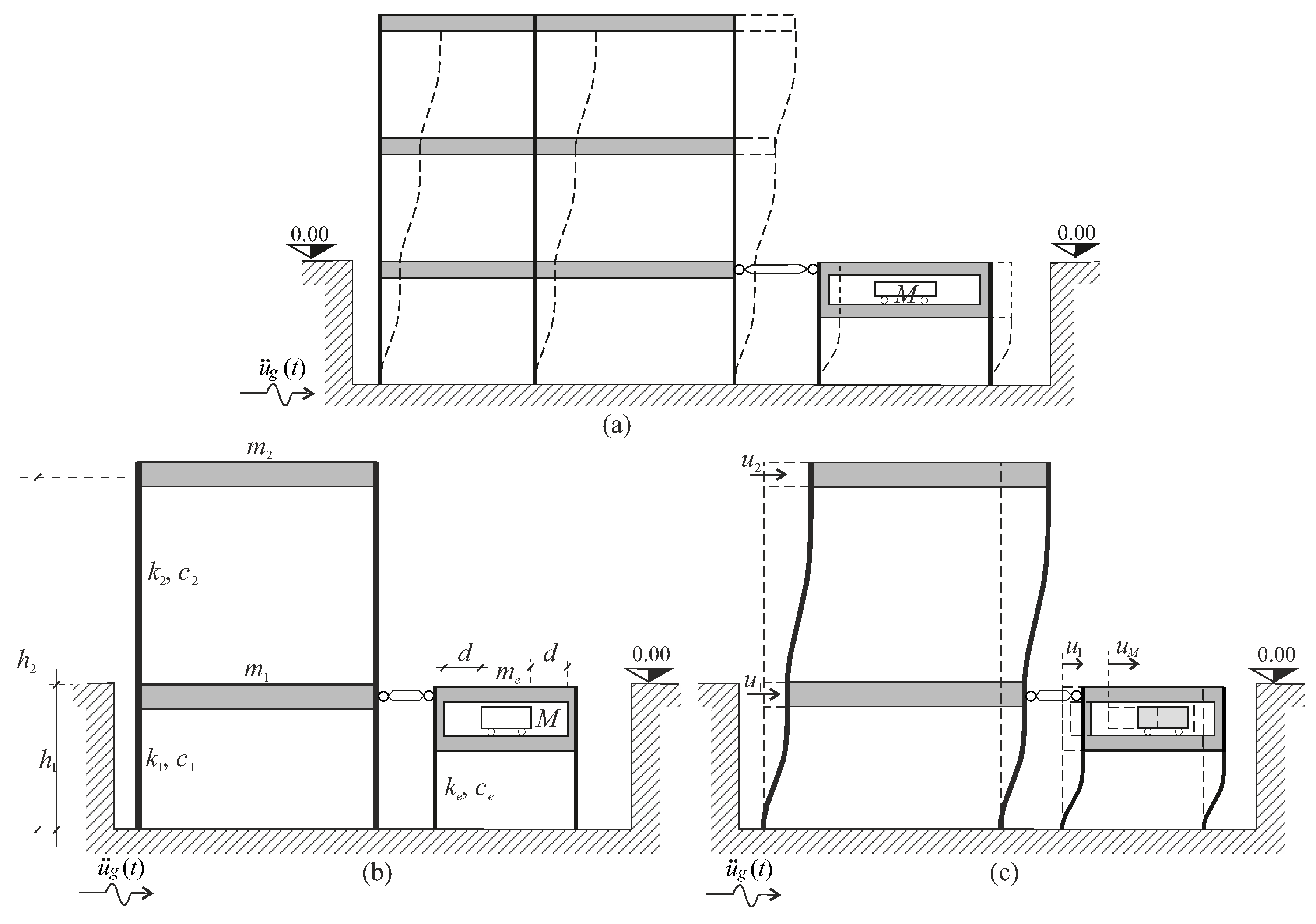
The studied mechanical system comprises a multi-degree-of-freedom (M-DOF) frame structure that is rigidly coupled to an external structure, which has its own stiffness and inertial mass, and is equipped with a vibro-impacting nonlinear energy sink (VI-NES). The external structure has a single story on which the VI-NES is positioned. The connection between the frame and external structures was assumed to be at the first story of the frame structure. In the case of a frame structure with an underground level, the external structure could be entirely beneath the ground level, thus avoiding interference with the aesthetic of the superstructure (i.e., the part of the structure above the connection level) (
Figure 1a).
The rigid connection between the frame and external structures allowed for modifications of the dynamical characteristics of the frame structure. Specifically, the stiffness and mass of the protection system (i.e., the external structure and VI-NES) directly contributed to the stiffness and mass of the first story of the structure that was to be protected, thereby altering its spectral characteristics. It is worth noting that, in many studies, the VI-NES is directly placed on a frame structure story and rigidly connected to it. Consequently, the impacting mass cannot be too large as it directly loaded onto the structural elements of that story. The proposed scheme of the protection system allows for the utilization of a higher impacting mass since it is placed on an external structure. Simultaneously, it introduces two new parameters, the mass and stiffness of the external structure, thus allowing for a more accurate optimization of the coupled structure.
2.1. Mechanical Model
To model the coupled system, the multi-degree-of-freedom frame structure was represented by a two-degree-of-freedom (2-DOF) equivalent system, which corresponds with a two-story shear-type frame structure. The mechanical characteristics (mass and stiffness) of the 2-DOF system were determined using the dynamic equivalence procedure proposed in [
3,
4,
32]. This dynamic equivalence yielded the mass
, stiffness
, and damping
(
) of the two equivalent stories, thus resulting in a low-dimensional mechanical model that effectively captured the main dynamics of the M-DOF frame structure. In contrast, the external structure was modeled as a 1-DOF mechanical system, where the VI-NES was embedded in its inertial mass (
Figure 1b). The protection system is characterized by mass
, stiffness
, and damping
, while
M represents the mass of the vibro-impacting mass (see
Figure 1b).
In total, the full coupled system is described by three Lagrangian parameters. Specifically,
and
represent the two degrees of freedom of the frame structure, whereas
is associated with the motion of the vibro-impacting mass (
Figure 1c). It is worth noting that the external structure embedding the vibro-impacting mass did not require any additional Lagrangian parameters as it was rigidly connected to the structure to be protected.
The Lagrangian parameter
corresponds to the displacement of the first floor, which is the floor where the protection system is connected to the structure. Similarly,
describes the displacement of the top story of the frame structure. In this manner, the quantity
represents the drift of the superstructure. The three equations of motion for the coupled mechanical system were obtained through a direct approach, and they can be expressed as follows:
where
is the ground acceleration. In Equation (
1), which represents the dynamical equilibrium associated with the Lagrangian parameter
, it is noteworthy that, due to the rigid connection between the structure and the protection system, the mass
, stiffness
, and damping
simply add to
,
, and
, respectively. The quantities
with
are the coefficients of the symmetric Rayleigh damping matrix of the stand-alone frame structure. Such a Rayleigh damping matrix is obtained by
In Equation (
4), the coefficients
and
are obtained assuming that the relative damping coefficients of both modes of the stand-alone frame structure have the same value, which are denoted as
. Finally, the damping
is obtained by treating the external structure as a 1-DOF system with a relative damping of
. Specifically,
, where
.
2.2. Ideal Impact Model
Equation (
3) describes the motion of the vibro-impacting mass
M. Since this paper aims to present a preliminary investigation into the effectiveness of the proposed protection system in reducing the seismic effects on a frame structure and does not delve into the details of the design of the protection system, an ideal model of the impacting mass was adopted. In the scientific literature, many refined models of impacting mass exist, such as the nonlinear elastic (Hertz) and viscoelastic (Tsuji, Kuwabara) models [
33,
34,
35]. A comparative study was conducted in [
36] to assess the effectiveness of a vibro-impacting nonlinear energy sink (VI-NES) in reducing seismic effects when it is directly connected to a frame structure story. The comparison involved different impact models, including the ideal one.
The main differences between an ideal model and a refined model is the time required to perform an impact. In the ideal model, the impact occurs instantly, whereas the refined models propose different ways through which to evaluate the duration of an impact. Such an estimated duration, in material that is sufficiently stiff, is of a small length, and it is always significantly less than a second. For this reason, it was deemed that the ideal model provides satisfactory results for a preliminary study. The results discussed in [
36] confirmed such an assumption.
As represented in
Figure 1, the mass
M with velocity
impacted the frame structure that possesses the mass
and velocity
. In the adopted ideal impact model, the post-impact velocities can be obtained as a function of the pre-impact velocities by solving the equations
where the superscript (−) denotes the pre-impact quantities, and the superscript (+) denotes the post-impact quantities. Equation (
5) provides the post-impact relative velocity between the impacting mass
M and the external structure
as a function of the corresponding pre-impact relative velocity through the restitution coefficient
r. It should be noted that, due to the rigid connection, the external structure has the same velocity as the first story of the main structure. Equation (
6) accounts for the conservation of horizontal momentum before and after the impact.
3. Parametric Analysis
The effectiveness of the proposed protection system was evaluated through a parametric analysis, which was performed by the varying several of the parameters that characterize the coupled system.
3.1. Parameters Characterizing the External Structure and the VI-NES
Stiffness ratio between the external structure and the first story of the frame structure:
Ratio between the elastic force
due to the clearance
d and the inertial force
due to the peak ground acceleration (PGA) of the earthquake:
Mass ratio between the vibro-impacting mass and the frame structure:
The restitution coefficient
r in Equation (
5).
It should be noted that, for the analyses, the mass of the external structure was set to .
3.2. Parameters Characterizing the Frame Structures Used in the Analyses
In the parametric analyses, two different multi-story frame structures were utilized, and their main characteristics are presented in
Table 1. In each multi-story frame structure, the mass, stiffness, and height of the stories were assumed to be constant at every level. The values in the last column, Main Period, represent the periods corresponding to the first vibration mode of the reference structures, which are modeled as multi-degree-of-freedom shear-type frame structures. This information was included as it constituted one of the essential inputs required for applying the dynamic equivalence criterion proposed in [
4].
By applying such a dynamic equivalence criterion to the frame structures in
Table 1, the characteristics of the corresponding 2-DOF models used in the analyses shown in
Table 2 were derived.
3.3. Gain Coefficients
To evaluate the effectiveness of the protection system in reducing the seismic effects on the frame structure, two different gain coefficients were introduced. They read as follows:
Here, the drift
denotes the difference in displacements provided by the uncoupled 2-DOF model, representing the seismic response of the uncoupled frame structure. The coefficient
informs about the effects of the coupling of the story connected to the protection system, whereas
is a metric for the effect of the coupling on the drift of the superstructure. According to Equation (
10), the values of
and
(when less than unity) indicate an effective performance of the protection system, as they signify a reduction in the displacement (and drift) of the coupled structure compared to that of the uncoupled structure.
The parametric analysis involved evaluating the gain coefficients and for each set of variable parameters and a single earthquake base motion, respectively. These values were then plotted in a specific parameter plane, thus resulting in gain maps.
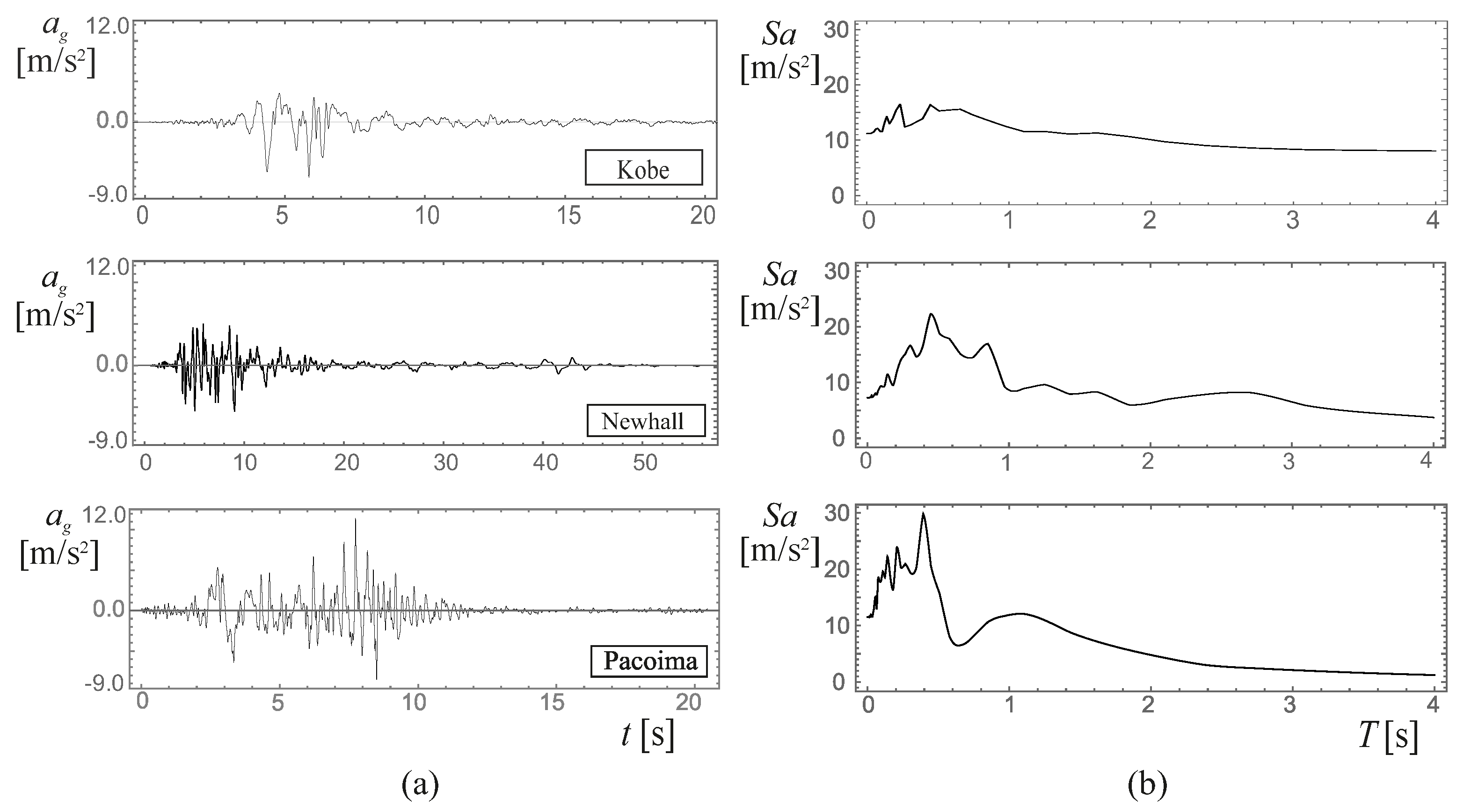
4. Seismic Excitation
A set of three earthquake records was used as excitation for the seismic analyses. The selection of the records was performed taking into account the differences in the spectral characteristics of the earthquake records. The intentional selection of three earthquake records, each demonstrating distinct spectral characteristics, enabled an initial evaluation of whether the seismic response of a frame structure can be enhanced with the proposed protection system. However, while adequate for the current analysis, and considering the preliminary nature of this investigation, the dataset of earthquake records should be significantly expanded for the examination of a real structure and for design purposes.
Figure 2 displays the time histories of the selected records in the left column and the corresponding pseudo-acceleration elastic spectra in the right column. The earthquake records considered were as follows:
- (a)
Kobe, 1995, Japan earthquake, Takarazuka station, ground level, position of the station: 34.8090 N, 135.3440 W;
- (b)
Northridge, Newhall, 1994, California earthquake, LA County Fire station no. 24279, 360 deg, position of the station: 34.387 N, 118.530 W;
- (c)
Pacoima, 1971, San Fernando, California earthquake, station no. 279, comp S16E, position of the station: 34.335 N, 118.3967 W.
In the following, each record is referred to by the underlined name from the above list. The results were obtained through a numerical integration of the equations of motion (Equations (
1)–(
3)), and this was achieved by considering the impact conditions specified in Equations (
5) and (
6).
The results are presented in gain maps, which are contour plots of the gain coefficients (Equation (
10)) in the parameter plane
(refer to Equations(
7) and (
8)). In the light gray regions of the map, the gain coefficient is below unity, indicating the efficacy of the protection system in reducing the seismic response of the frame structure. Conversely, in the dark gray regions, the gain coefficients exceed unity, thus indicating a lack of advantage in using the protection system.
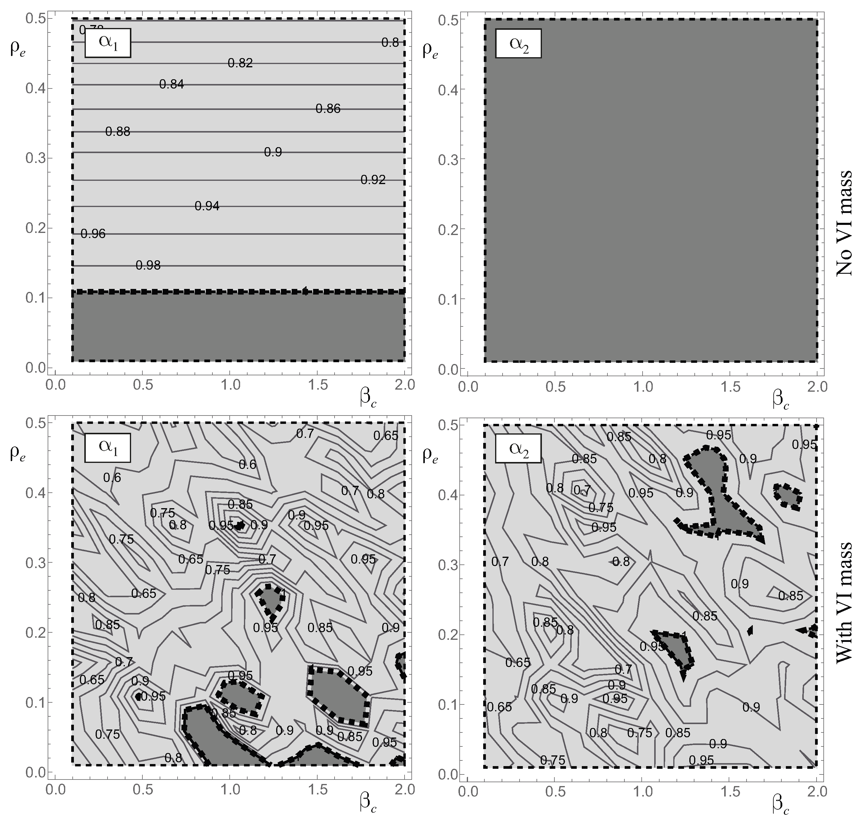
4.1. The Role of the Stiffness of the External Structure and the Clearance of the VI-NES
The initial analysis aims to examine the influence of the parameters
and
. Maps of the gain coefficients
and
are generated, maintaining constant characteristics for the frame structure (Frame 1, as detailed in
Table 2), along with fixed coefficients
and
. The excitation is provided by the Kobe earthquake record.
Figure 3 displays gain maps for two distinct coupled systems. The maps in the first row pertain to a frame structure that was coupled with an external structure with a total mass equal to
. Those in the second row correspond to a frame structure coupled with an external structure of mass
, which was equipped with a vibro-impacting mass
M. As the total mass of the two systems remained the same, comparing the results of these two cases revealed the advantage of having a moving (and impacting) mass rather than a fixed one.
When the mass is fixed, a reduction is observed only in the displacements of the story directly connected to the external structure, as indicated by the advantage region (light gray region) in the map. Conversely, in this system, there is no reduction in the drift of the superstructure, as evidenced by the dark gray region that encompasses the entire map. It should be noted that, given the fixed mass, the clearance of the vibro-impacting mass does not impact the behavior of the system. Consequently, the two maps could be represented by a single section each. However, presenting the results as separate maps is necessary for the purpose of comparison with the case featuring the vibro-impacting mass.
The utilization of VI-NES significantly enhances the seismic behavior of the coupled structure. This improvement is evident in the bottom maps of
Figure 3, where the advantage regions now encompass nearly the entire parameter plane in both the
and
maps. The two maps show that the vibro-impacting mass can significantly reduce the displacement of the connection floor with a
reduction in
compared to the
reduction observed in the previous case. Additionally, the drift of the superstructure is reduced by approximately
compared to the drift of the uncoupled frame structure. Both maps show points of a relative minimum (i.e., points where the maximum reduction of displacements occurs). The minima in the
and
maps were not perfectly coincident, although they were quite close to each other. A suitable choice of the parameters
and
would allow for optimizing the performance of the coupled system.
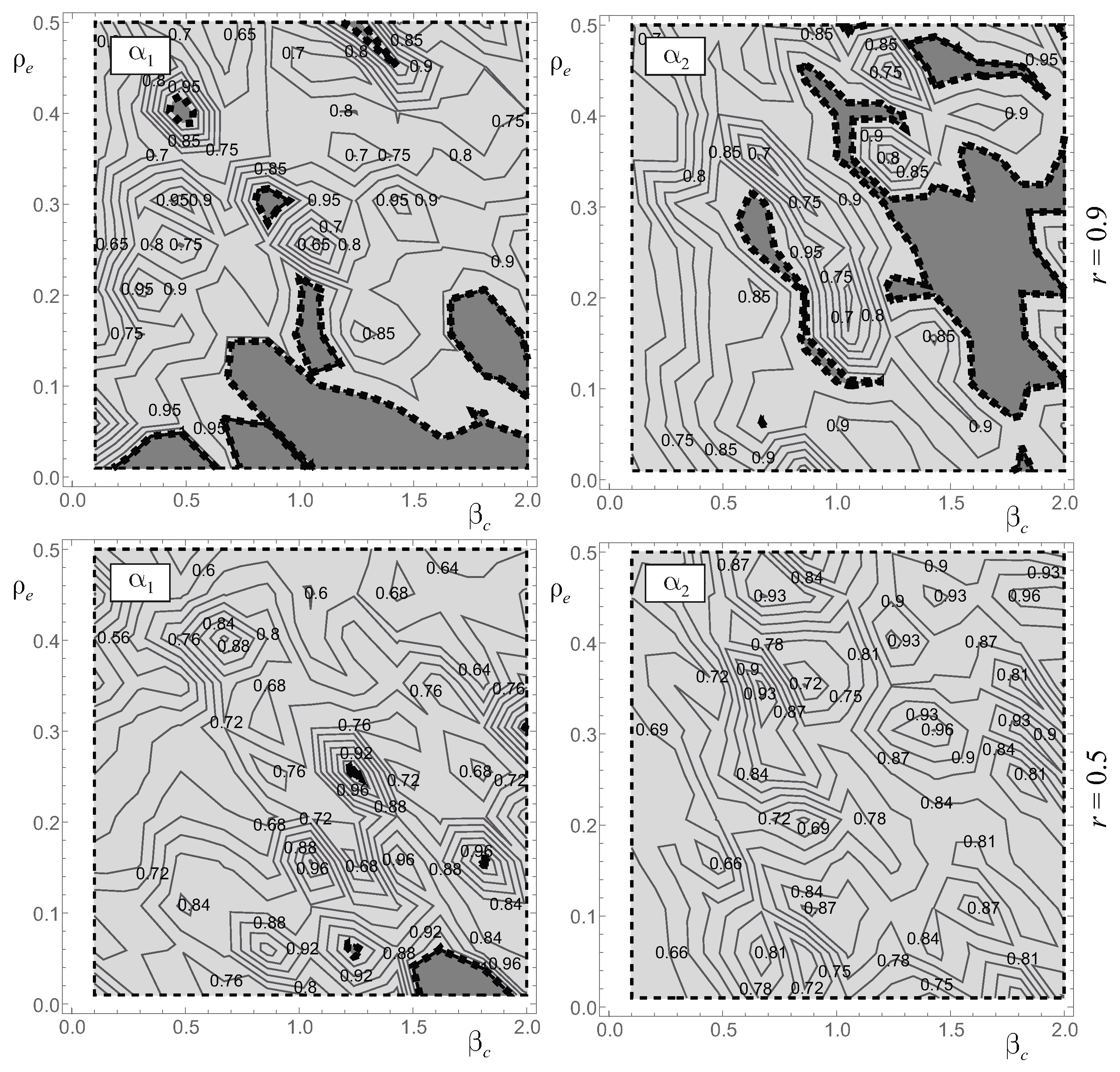
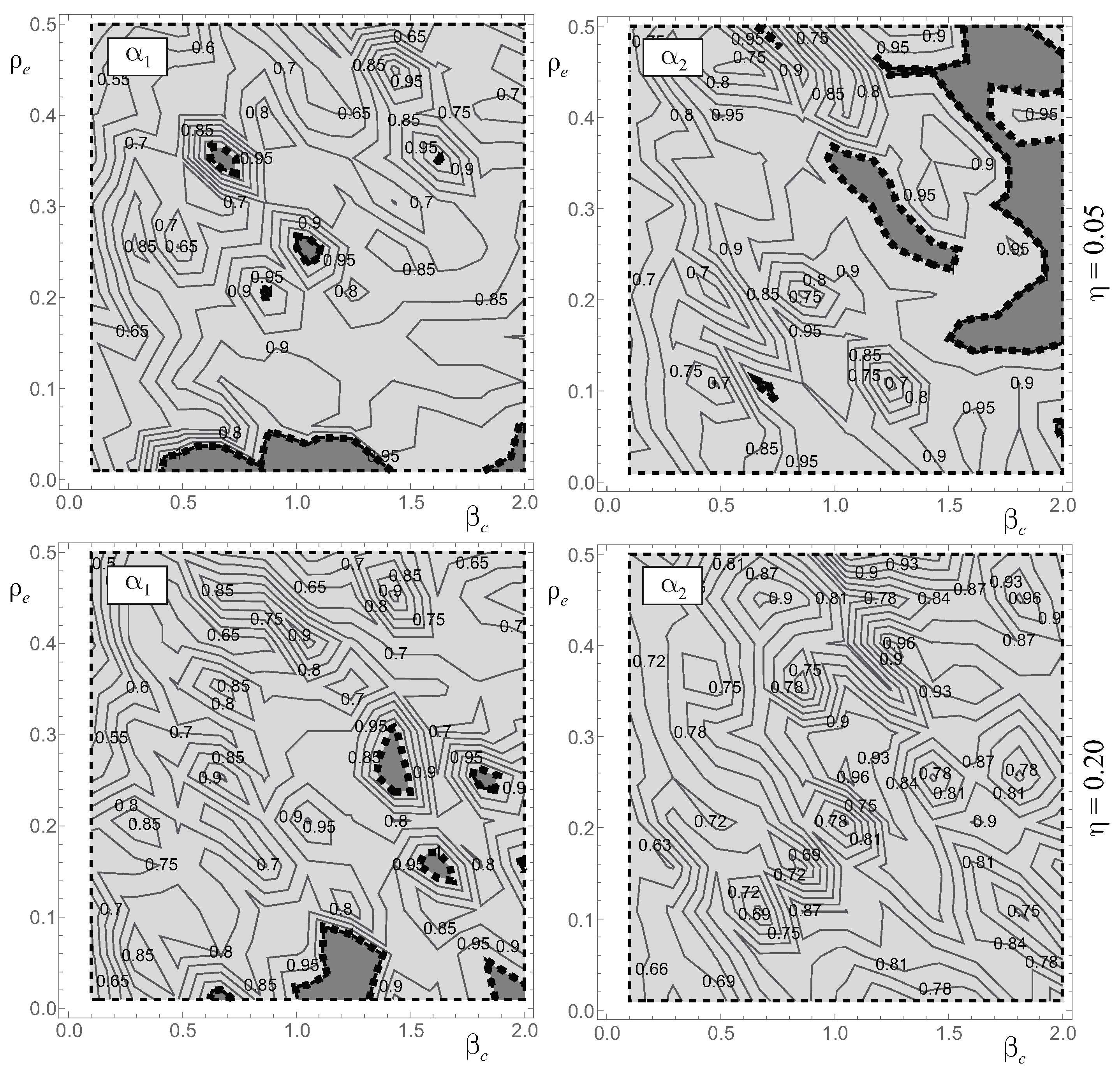
4.2. The Role of the Restitution Coefficient and the Mass of the VI-NES
This section analyzes the influence of the restitution coefficient
r first and then the mass
M of the VI-NES. Given that this paper is an initial study aimed at assessing the effectiveness of the proposed external device when equipped with VI-NES in reducing seismic effects in frame structures, the restitution coefficient is treated as a variable parameter, thus following the approach outlined in [
27]. The results related to
r displayed in
Figure 4 refer to Frame 1 (see
Table 2), the constant
M (
), and the excitation provided by the Kobe earthquake record. The maps in the top row of
Figure 4 were obtained for
, whereas those in the bottom row are for
.
The reduction of the restitution coefficient, corresponding to an increase in the energy dissipation of the VI-NES, significantly affected the gain maps. The primary impact of a decrease in r was observed in the extent of the advantage regions (light gray areas) rather than the values of the gain coefficients. Specifically, for , the maps revealed a larger advantage region that encompassed almost the entire parameter plane. This suggested a greater number of combinations of parameter values for which the protection device proved effective. However, while the positions of the relative minima of the gain coefficients were influenced by r, a decrease in r did not result in significant reductions in the minimum values of and . Upon examining the graphs in the first column, the minimum values of were for and for . Similarly, the minimum value of changes from for and for .
Figure 5 investigates the influence of the mass of the VI-NES
M through a variation of
. The top row of
Figure 5 includes the maps obtained for
, and the bottom row includes those for
. The comparison among the respective maps shows that the increase of
M was more beneficial for the superstructure because it mostly results in a wider advantage region in the
map obtained for
. The comparison of the values of the gain coefficients between maps shows that the increase of
M leads to larger values of
, which correspond to larger displacements of the connection story (the first story of the frame structure). The drift of the superstructure, conversely, benefits from an increase in
M, as the values of
obtained for
are generally smaller than those obtained for
.
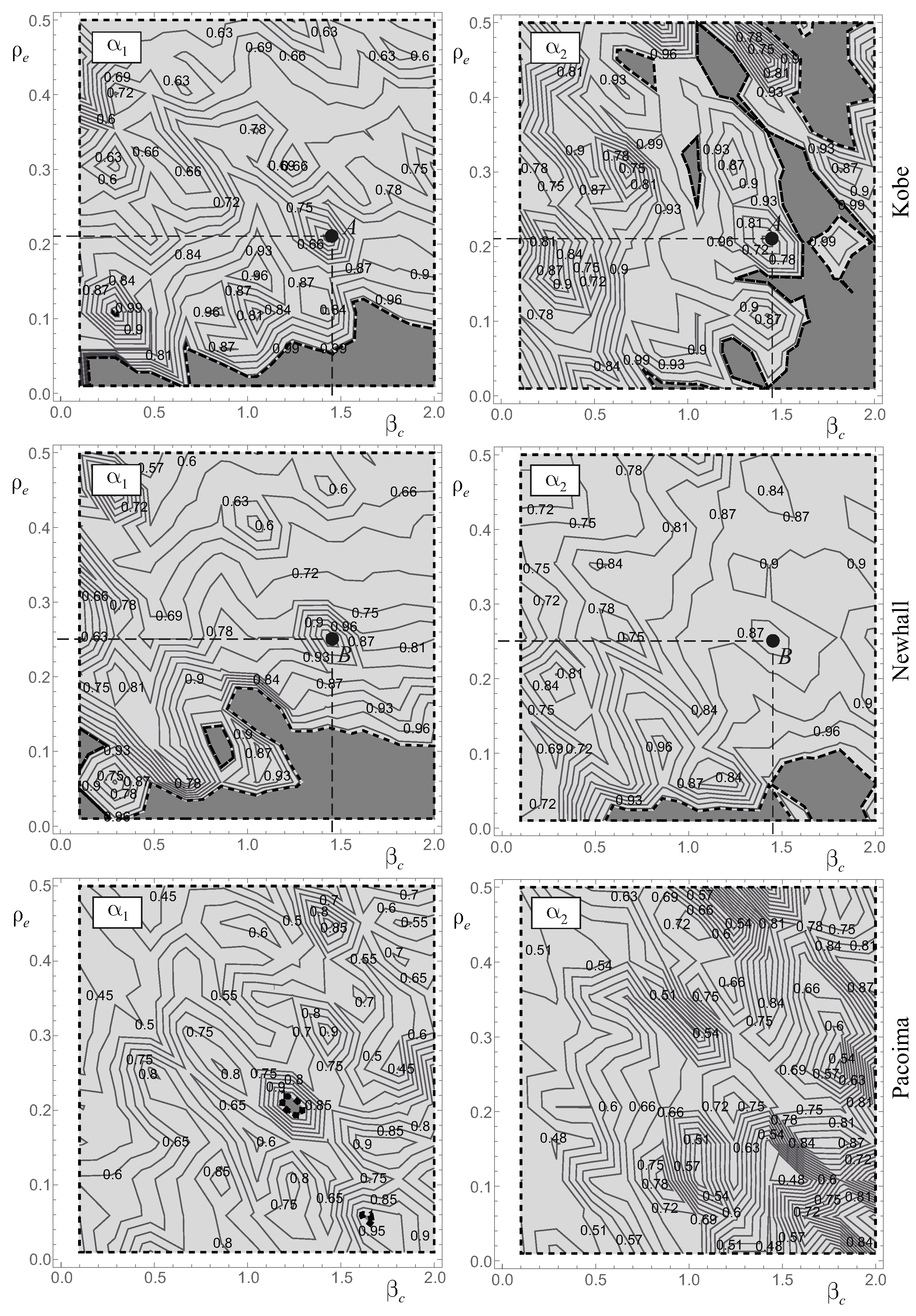
4.3. Comparison of Results from Various Earthquake Records
This section explores the comparison of results obtained with the three previously presented earthquake records (Kobe, Newhall, and Pacoima) for the two frame structures detailed in
Table 1 and
Table 2. The analysis was carried out under a constant
M (
) and
. In
Figure 6, gain maps for both coefficients related to Frame 2 are depicted; each row represents results from a different earthquake.
As expected, the values of the gain coefficient significantly depended on the earthquake records. The size of the advantage regions, the minimum values of and , and the position of the relative minimum points all varied according to the used record. Overall, the best seismic behavior (i.e., the smallest displacements) of the coupled system was observed under the Pacoima earthquake. In this case, the advantage regions covered the entire parameter plane, and the protection system reduced the displacements of the structure (both and ) by up to of those of the uncoupled structure.
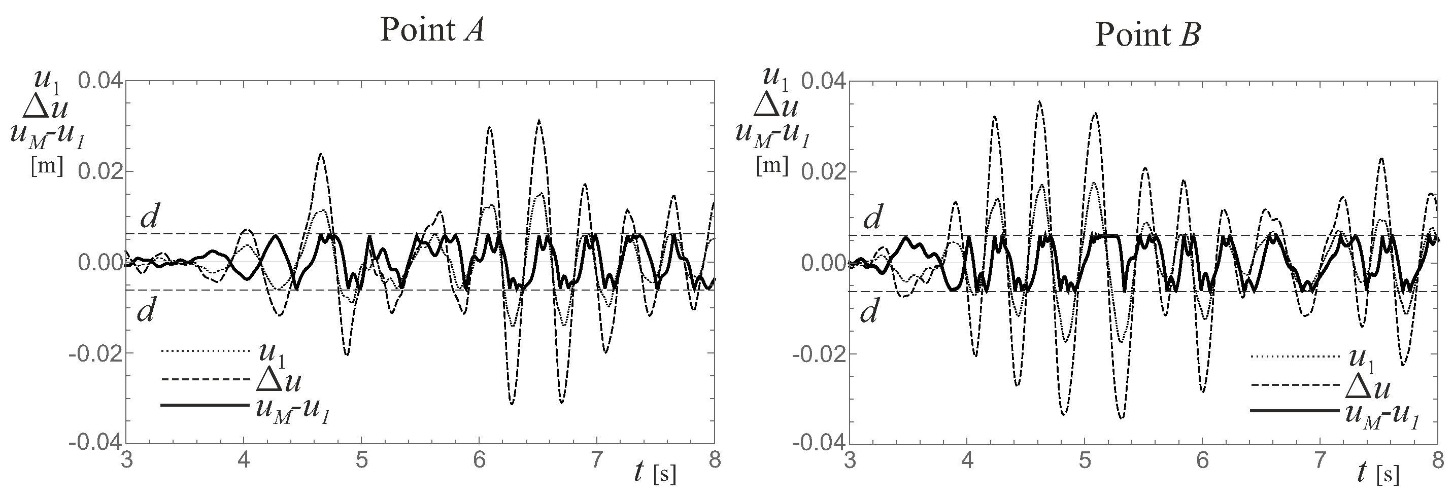
Figure 7 presents the analysis of the time histories of the coupled systems characterized by the values of
and
at points
A and
B marked in
Figure 6. Such analysis is intended to provide a deeper understanding of the protection system’s behavior in reducing the displacements of the frame structure. These points were carefully chosen to be in proximity to the relative minimum points of both the
and
maps in correspondence with the same values of
. The graph on the left corresponds to point
A, while that on the right pertain to point
B. Both graphs depict the time histories of the displacement of the connection story
(dotted line) and drift of the superstructure
(dashed line) together with the relative motion of the vibro-impacting mass
(solid line). The horizontal dashed lines correspond to the clearance
d of the VI-NES, thereby representing the upper threshold of the displacement of the vibro-impacting mass at which an impact occurs. Since the two graphs were derived for the same value of
, the value of
d was also consistent between the two cases. In correspondence with the initial impacts of the vibro-impacting mass, its motion was almost in a counterphase with the displacements of the frame structure. Therefore, the protection system functions similarly to a tuned mass damper. After the initial impacts, the vibro-impacting mass remained slightly out of phase with the motion of the frame structure, thus limiting the displacements of the frame structure and providing energy dissipation through the impacts.
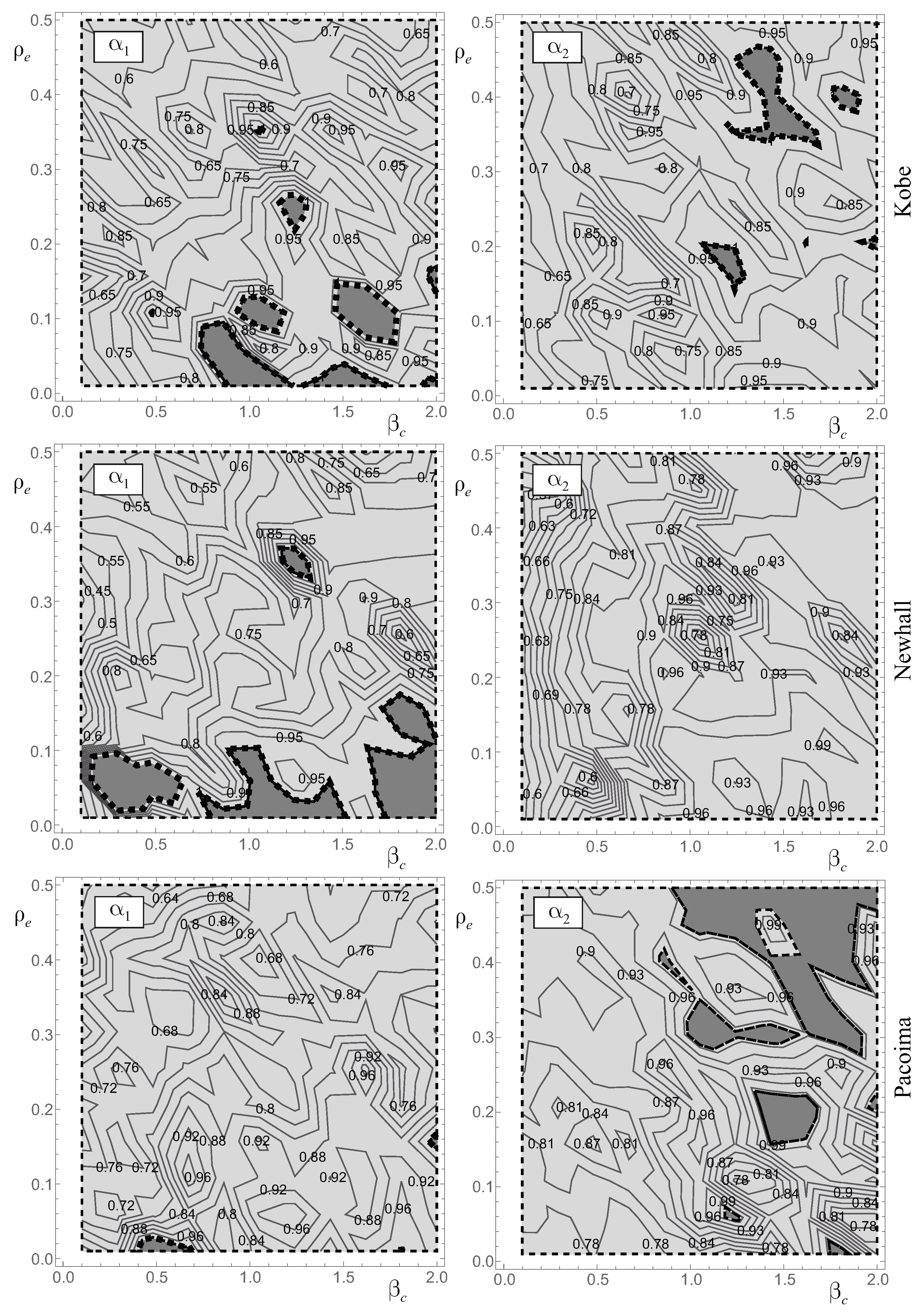
Finally,
Figure 8 displays the
and
gain maps of Frame 1. The maps in each row correspond to a different earthquake. Also for Frame 1, the gain maps strongly depend on the characteristics of the earthquake record, thereby affecting the extension of the advantage regions, the minimum values of the gain coefficients, and their positions. Unlike the results presented for Frame 2, in this case, the smallest displacements were obtained under the Newhall earthquake record.
Although the results in
Figure 6 and
Figure 8 consider the same protection system (
and
), the gain coefficients for Frame 1 were slightly higher than those for Frame 2. This difference could be attributed to the varying height between Frame 1, which consists of four stories, and Frame 2, a three-story frame (see
Table 1). One might reasonably expect that the effectiveness of the protection system, which was consistently connected to the first story of the frame, would decrease with an increase in the number of stories. While this limitation was present in the use of the proposed protection system, the findings of this paper suggest that connections at various story levels could be analyzed using the same approach presented here.
5. Conclusions
This paper explores the feasibility of designing a seismic protection system based on a vibro-impacting nonlinear energy sink. In contrast to the existing literature, the vibro-impacting mass was positioned on an external structure with limited height, and it was connected to the first story of the frame structure to be protected. The coupled system is represented by a low-dimensional structural model with only three degrees of freedom. The mechanical characteristics of the reduced model were determined using a dynamic equivalence procedure that was previously developed by one of the authors of this paper. Given that this paper primarily focuses on an initial feasibility assessment of the proposed protection system, a simplified, ideal model that assumes an instantaneous impact was employed for the vibro-impacting mass.
A comprehensive parametric analysis was conducted involving variations in several parameters that characterize the external structure, the vibro-impacting mass, and the frame structure intended for protection. Three earthquake records were employed to excite the structure. The seismic effectiveness of coupling with the proposed protection system was evaluated using two gain coefficients, which were defined as the ratio between the displacements of the coupled and uncoupled frame structures. Values below unity for these coefficients indicated an advantage in using the proposed protection system. The results of the parametric analyses were presented in gain maps, thereby illustrating the contour plots of the gain coefficients in specific parameter planes.
The results obtained from the frame structure coupled with the proposed protection system were compared to those achieved using a protection system with a fixed (non-vibro-impacting) mass. The comparison aimed to clarify the performance of the vibro-impacting mass. The findings revealed that the vibro-impacting mass effectively reduced the displacement of both the connected story and the superstructure in contrast to the protection system with a fixed mass. In the specific scenario considered, it was feasible to reduce the displacements of the connection story by an additional 20% compared to a structure without a protection device. More notably, there was a significant reduction in the drift of the superstructure, a benefit not observed when the vibro-impacting mass was not taken into account. Increasing the mass of the vibro-impacting nonlinear energy sink demonstrated effectiveness in safeguarding both the connection story and the superstructure, each in distinct ways. The augmentation in mass resulted in an additional 10% reduction in displacements for the connection story. Simultaneously, it extended the advantage region for the superstructure. Furthermore, the analyses demonstrated the relation between the effectiveness of the vibro-impacting mass and the restitution coefficient, as well as the stiffness of the external structure. A decrease in the restitution coefficient led to an expansion of the advantage regions but only to a limited reduction of the gain coefficients. An increase in the stiffness ratio between the external structure and the first story of the frame structure generally resulted in a decrease in the value of the gain coefficients. A judicious selection of these two parameters enabled the optimization of the proposed protection system’s performance.
The effectiveness of the proposed protection system was constrained by opting to limit the connection height to the first floor of the frame structure. This decision was driven by considerations of both aesthetics and economics. However, future studies focusing on taller structures could explore the relationship between the efficacy of the proposed protection system and the height of the connection. It should also be considered that this investigation indicates the proposed protection method as a viable means through which to enhance the seismic safety of a frame structure, but it does not provide clear indications on the parameter values for a real structure. The determination of such parameters would necessitate analyses to be conducted with a larger set of earthquake records. The importance of employing a larger set of earthquake records is clearly conveyed by the significant differences between the results obtained for the two considered structures subjected to the same seismic excitation.
Author Contributions
Conceptualization, A.D.E. and A.C.; Methodology, A.D.E. and A.C.; Investigation, A.D.E. and A.C.; Writing—original draft, A.D.E. and A.C.; Writing—review & editing, A.D.E. and A.C. All authors have read and agreed to the published version of the manuscript.
Funding
This research received no external funding.
Data Availability Statement
The data, models, or code generated or used during the study are available from the corresponding authors on request. The data are not publicly available due to privacy.
Conflicts of Interest
The authors declare no conflicts of interest.
References
- Kelly, J. Base isolation: Linear theory and design. Earthq. Spectra 1995, 6, 223–244. [Google Scholar] [CrossRef]
- Chey, M.; Chase, J.; Mander, J.B.; Carr, A. Innovative seismic retrofitting strategy of added stories isolation system. Front. Struct. Civ. Eng. 2013, 7, 13–23. [Google Scholar] [CrossRef]
- Fabrizio, C.; Di Egidio, A.; de Leo, A. Top disconnection versus base disconnection in structures subjected to harmonic base excitation. Eng. Struct. 2017, 152, 660–670. [Google Scholar] [CrossRef]
- Fabrizio, C.; de Leo, A.; Di Egidio, A. Tuned mass damper and base isolation: A unitary approach for the seismic protection of conventional frame structures. J. Eng. Mech. 2019, 145, 04019011. [Google Scholar] [CrossRef]
- Wang, S.J.; Hwang, J.S.; Chang, K.C.; Lin, M.H.; Lee, B.H. Analytical and experimental studies on midstory isolated buildings with modal coupling effect. Earthq. Eng. Struct. Dyn. 2013, 42, 201–219. [Google Scholar] [CrossRef]
- Pagliaro, S.; Di Egidio, A. Archetype dynamically equivalent 3-d.o.f. model to evaluate seismic performances of intermediate discontinuity in frame structures. J. Eng. Mech. 2022, 148, 04022004. [Google Scholar] [CrossRef]
- Di Egidio, A.; Pagliaro, S.; Contento, A. Seismic Performances of Frame Structures with Hysteretic Intermediate Discontinuity. Appl. Sci. 2023, 13, 5373. [Google Scholar] [CrossRef]
- Villaverde, R.; Mosqueda, G. Aseismic roof isolation system: Analytic and shake table studies. Earthq. Eng. Struct. Dyn. 1999, 28, 217–234. [Google Scholar] [CrossRef]
- Den Hartog, J.P. Mechanical Vibrations, 4th ed.; McGraw-Hill: New York, NY, USA, 1956. [Google Scholar]
- Marian, L.; Giaralis, A. Optimal design of a novel tuned mass-damper-inerter (TMDI) passive vibration control configuration for stochastically support-excited structural systems. Probabilistic Eng. Mech. 2014, 38, 156–164. [Google Scholar] [CrossRef]
- Brzeski, P.; Kapitaniak, T.; Perlikowski, P. Novel type of tuned mass damper with inerter which enables changes of inertance. J. Sound Vib. 2015, 349, 56–66. [Google Scholar] [CrossRef]
- Pietrosanti, D.; De Angelis, M.; Basili, M. Optimal design and performance evaluation of systems with Tuned Mass Damper Inerter (TMDI). Earthq. Eng. Struct. Dyn. 2017, 46, 1367–1388. [Google Scholar] [CrossRef]
- De Domenico, D.; Ricciardi, G. An enhanced base isolation system equipped with optimal tuned mass damper inerter (TMDI). Earthq. Eng. Struct. Dyn. 2018, 47, 1169–1192. [Google Scholar] [CrossRef]
- De Domenico, D.; Impollonia, N.; Ricciardi, G. Soil-dependent optimum design of a new passive vibration control system combining seismic base isolation with tuned inerter damper. Soil Dyn. Earthq. Eng. 2018, 105, 37–53. [Google Scholar] [CrossRef]
- Giaralis, A.; Taflanidis, A. Optimal tuned mass-damper-inerter (TMDI) design for seismically excited MDOF structures with model uncertainties based on reliability criteria. Struct. Control Health Monit. 2018, 25, e2082. [Google Scholar] [CrossRef]
- Pietrosanti, D.; De Angelis, M.; Basili, M. A generalized 2-DOF model for optimal design of MDOF structures controlled by Tuned Mass Damper Inerter (TMDI). Int. J. Mech. Sci. 2020, 185, 105849. [Google Scholar] [CrossRef]
- De Domenico, D.; Deastra, P.; Ricciardi, G.; Sims, N.D.; Wagg, D.J. Novel fluid inerter based tuned mass dampers for optimised structural control of base-isolated buildings. J. Frankl. Inst. 2019, 356, 7626–7649. [Google Scholar] [CrossRef]
- Di Egidio, A.; Pagliaro, S.; Contento, A. Elasto-plastic short exoskeleton to improve dynamic and seismic performances of frame structures. Appl. Sci. 2022, 12, 10398. [Google Scholar] [CrossRef]
- Scudieri, G. Adaptive building exoskeletons, a biomimetic model for the rehabilitation of social housing. Int. J. Archit. Res. 2015, 9, 134–143. [Google Scholar] [CrossRef]
- Boake, T. Diagrid Structures: Systems-Connections-Details; Birkhauser: Basel, Switzerland, 2014. [Google Scholar]
- Di Egidio, A.; Pagliaro, S.; Contento, A. Seismic benefits of deformable connections between a frame structure and an external structure with inerter. Eng. Struct. 2022, 256, 113025. [Google Scholar] [CrossRef]
- Di Egidio, A.; Contento, A. Seismic Benefits from Coupling Frame Structures with a Hysteretic Mass Damper Inerter. Appl. Sci. 2023, 13, 5017. [Google Scholar] [CrossRef]
- Aghagholizadeh, M.; Makris, N. Earthquake response analysis of yielding structures coupled with vertically restrained rocking walls. Earthq. Eng. Struct. Dyn. 2018, 47, 2965–2984. [Google Scholar] [CrossRef]
- Pagliaro, S.; Aloisio, A.; Di Egidio, A.; Alaggio, R. Rigid block coupled with a 2 d.o.f. system: Numerical and experimental investigation. Coupled Syst. Mech. 2020, 6, 539–562. [Google Scholar]
- Di Egidio, A.; Pagliaro, S.; Fabrizio, C. Combined use of rocking wall and inerters to improve the seismic response of frame structures. J. Eng. Mech. 2021, 147, 04021016. [Google Scholar] [CrossRef]
- Di Egidio, A.; Pagliaro, S.; Fabrizio, C.; de Leo, A. Seismic performance of frame structures coupled with an external rocking wall. Eng. Struct. 2020, 224, 111207. [Google Scholar] [CrossRef]
- Nucera, F.; Vakakis, A.F.; McFarland, D.M.; Bergman, L.A.; Kerschen, G. Targeted energy transfers in vibro-impact oscillators for seismic mitigation. Nonlinear Dyn. 2007, 50, 651–677. [Google Scholar] [CrossRef]
- Nucera, F.; McFarland, D.; Bergman, L.; Vakakis, A. Application of broadband nonlinear targeted energy transfers for seismic mitigation of a shear frame: Computational results. J. Sound Vib. 2010, 329, 2973–2994. [Google Scholar] [CrossRef]
- Ahmadi, M.; Attari, N.; Shahrouzi, M. Structural seismic response mitigation using optimized vibro-impact nonlinear energy sinks. J. Earthq. Eng. 2015, 19, 193–219. [Google Scholar] [CrossRef]
- Gendelman, O. Analytic treatment of a system with a vibro-impact nonlinear energy sink. J. Sound Vib. 2012, 331, 4599–4608. [Google Scholar] [CrossRef]
- Wei, X.; Fu, B.; Wu, W.; Liu, X. Effects of Vertical Ground Motion on Pedestrian-Induced Vibrations of Footbridges: Numerical Analysis and Machine Learning-Based Prediction. Buildings 2022, 12, 2138. [Google Scholar] [CrossRef]
- Fabrizio, C.; de Leo, A.; Di Egidio, A. Structural disconnection as a general technique to improve the dynamic and seismic response of structures: A basic model. Procedia Eng. 2017, 199, 1635–1640. [Google Scholar] [CrossRef]
- Kuwabara, G.; Kono, K. Restitution coefficient in a collision between two spheres. Jpn. J. Appl. Phys. 1997, 26, 1230–1233. [Google Scholar] [CrossRef]
- Tsuji, Y.; Tanaka, T.; Ishida, T. Lagrangian numerical simulation of plug flow of cohesionless particles in a horizontal pipe. Powder Technol. 1992, 71, 239–250. [Google Scholar] [CrossRef]
- Antypov, D.; Elliott, J. On an analytical solution for the damped Hertzian spring. Europhys. Lett. 2011, 94, 50004. [Google Scholar] [CrossRef]
- Lo Feudo, S.; Job, S.; Cavallo, M.; Fraddosio, A.; Piccioni, M.; Tafuni, A. Finite contact duration modeling of a Vibro-Impact Nonlinear Energy Sink to protect a civil engineering frame structure against seismic events. Eng. Struct. 2022, 259, 114137. [Google Scholar] [CrossRef]
| Disclaimer/Publisher’s Note: The statements, opinions and data contained in all publications are solely those of the individual author(s) and contributor(s) and not of MDPI and/or the editor(s). MDPI and/or the editor(s) disclaim responsibility for any injury to people or property resulting from any ideas, methods, instructions or products referred to in the content. |
© 2024 by the authors. Licensee MDPI, Basel, Switzerland. This article is an open access article distributed under the terms and conditions of the Creative Commons Attribution (CC BY) license (https://creativecommons.org/licenses/by/4.0/).


