Article

Natural Frequency Response of FG-CNT Coupled Curved Beams in Thermal Conditions

by
Amir R. Masoodi
1,*,
Moein Alreza Ghandehari
1,
Francesco Tornabene
2,* and
Rossana Dimitri
2
1
Department of Civil Engineering, Ferdowsi University of Mashhad, Mashhad 9177948974, Iran
2
Department of Innovation Engineering, University of Salento, 73100 Lecce, Italy
*
Authors to whom correspondence should be addressed.
Appl. Sci. 2024, 14(2), 687; https://doi.org/10.3390/app14020687
Submission received: 18 December 2023 / Revised: 8 January 2024 / Accepted: 11 January 2024 / Published: 13 January 2024
(This article belongs to the Section Nanotechnology and Applied Nanosciences)

Abstract

:
This study investigates the sensitivity of dynamic properties in coupled curved beams reinforced with carbon nanotubes (CNTs) to thermal variations. Temperature-dependent (TD) mechanical properties are considered for poly methyl methacrylate (PMMA) to be strengthened with single-walled CNTs (SWCNTs), employing the basic rule of mixture to define the equivalent mechanical properties of nanocomposites. The governing equations of motion are derived using a first-order shear deformation theory (FSDT) and Hamilton’s principle, accounting for elastic interfaces modeled using elastic springs. A meshfree solution method based on a generalized differential quadrature (GDQ) approach is employed to discretize the eigenvalue problem and to obtain the frequency response of the structure. The proposed numerical procedure’s accuracy is verified against predictions in the literature for homogeneous structural cases under a fixed environmental temperature. The systematic investigation assesses the impact of various geometric and material properties, including curvature, boundary conditions, interfacial stiffness, and CNT distribution patterns, on the vibrational behavior.

1. Introduction

Among novel structural systems in civil engineering, coupled beams have increasingly been used in the last decades for highways, subgrades, and other facilities. This kind of system consists of beams with a straight or curved geometry, connected by an elastic layer, with a linear, non-linear, and plastic behavior. Despite the large amount of studies from the literature focusing on the structural behavior of single beams [1,2,3,4], some static and dynamic aspects for coupled beam systems have already been explored in the pioneering works by Seelig and Hoppmann [5] and Dublin and Friedrich [6], drawing increased attention from researchers in the recent years. These studies focused on static and dynamic behavior [7,8,9], transverse vibration [10], and forced vibration [11], using viscously damped interlayer [8,12] among others. Among the most recent works, we can find studies focusing on the dynamic response of coupled curved beams, including both singly curved [13,14,15,16] and doubly curved systems [17,18,19].
The earliest research on the vibrational behavior of beams resting on an elastic foundation was performed by Mathews [20,21] and Eisenberger [22], involving one or two foundation parameters. Several researchers have recently been concerned with obtaining the natural frequencies of a curved beam with different geometries, loading, boundary conditions, and elastic foundations [23,24,25,26,27,28,29,30]. Although few studies have assessed the vibration of homogeneous coupled beams [31,32,33,34,35,36], research has focused on the effect of nanomaterials on the frequency behavior of these systems. Recently, Han et al. [37] have presented an exact solution to define the dynamic characteristics of double-beam systems using an improved Wittrick–Williams algorithm. The vibrational behavior of a double-beam system connected to a viscoelastic layer was also studied [38]. Additionally, numerical studies have been performed to determine the damping properties of a system using two beams [39].
Advanced nanomaterials and their application have also motivated many studies to investigate their possible application in civil (structural and geotechnical) engineering, to create more efficient and sustainable materials [40,41]. Among them, single-layered hollow tubes are largely used as single-walled carbon nanotubes with diameter 0.4 to 2 mm [42]. Functionally graded materials (FGMs) have been also proposed for their high performance, capacity, and low weight with an overall improvement of the mechanical behavior of the structure due to a non-uniform distribution of the material along different directions. Among them, functionally graded carbon nanotubes (FG-CNTs) represent the most common type of nanocomposite used in many structural members, such as beams, plates, and shells [43,44,45,46,47,48,49,50,51]. Ong et al. [52] investigated the dynamic response of double-beam systems in which CNTs were used as the reinforcing phase in the structure with different distribution patterns. In the further work [53], the authors focused on the natural frequency of FG-CNT reinforced double beam systems in a thermal environment, where FG-CNTs stand for the reinforcing phase. The dynamic behavior of nanocomposite coupled beam systems is still being considered by different researchers. In such a context, many scientists have continued to investigate the dynamic responses of structures over the past few decades, accounting for different analytical solutions such as GDQ and DSC [54,55,56,57,58]. The GDQ approach is a semi-analytical solution method with a fast convergence rate, as largely demonstrated in many applications of beams, plates, and shells [59,60,61,62,63,64,65,66,67,68,69,70,71,72] for different curved geometries, both in a static and dynamic sense. It is crucial to satisfy the boundary conditions accurately in order to obtain reliable and accurate solutions. It is worth mentioning that there is only one boundary condition that must be satisfied at each boundary point of a second-order differential equation describing a Timoshenko beam. For this reason, in a GDQ method, the discrete boundary conditions can be placed at the boundary points.
Starting with the literature overview, the vibrational behavior of curve coupled beams seems to be an interesting and relevant topic of structural engineering, possibly introducing a beneficial and efficient procedure for investigating their dynamic behavior, especially for nanomaterial reinforcements. This corresponds to the main purpose of the present work, which considers the effect of temperature on the frequency response of the selected systems, involving thermal-dependent mechanical properties for each phase. Notably, our novelty lies in the exploration of temperature-dependent (TD) mechanical properties, specifically focusing on poly methyl methacrylate (PMMA) strengthened with single-walled CNTs (SWCNTs). The unique aspect is the application of the basic rule of mixture to define equivalent mechanical properties for nanocomposites with TD characteristics. The equivalent mechanical properties of the composite material reinforced with CNTs are determined using a simple rule of mixture, where the governing equation of the beam is obtained by means of the Hamiltonian principle, which is then solved in discrete form based on the GDQ method. A validation study is performed against the reference literature to show the correctness and accuracy of the proposed procedure, where a systematic investigation examines the sensitivity of the frequency response to different input parameters, for both thermal-dependent and independent mechanical parameters of the composite material. Our analysis extends beyond the existing literature by comprehensively assessing the vibrational behavior of the structure under these varied conditions.

2. CNT Beams Material Properties

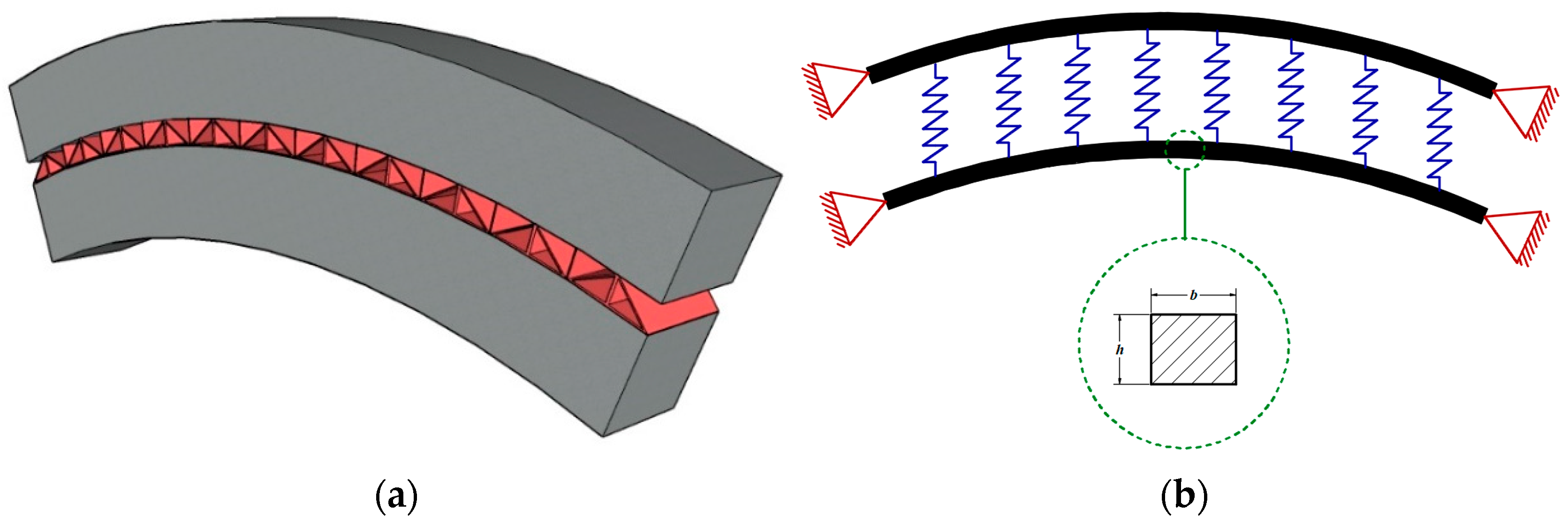
Let us consider a coupled curved CNT beam, with two curved beams connected with a layer of linear springs. The geometry of beams is described by a radius R, length L, central angle θ, and transverse width and height, b and h, respectively, of the beam section. Different combinations of boundary conditions can be considered per beam, namely, clamped–clamped (C-C), clamped–simply supported (C-S), clamped–free (C-F) or simply–simply supported (S-S). Figure 1 shows a simply supported (S-S/S-S) curved system with θ = 45 ° made of a composite material reinforced with CNTs.
More specifically, the selected example considers a PMMA matrix and SWCNTs (10,10) as the reinforcement phase. Five types of reinforcement patterns are used here, including a uniform distribution of CNTs (UD-CNTs), as well as FG distributions of CNTs of type V, Λ, O, and X, as depicted in Figure 2.
From an analytical standpoint, for example, a Λ−type variation of a function in the z direction can be defined as [29]
F ( z ) = ( 1 2 z h ) n             h 2 z h 2
In the particular case of CNTs volume fraction varying with a Λ distribution, it is
V C N T ( z ) = ( n + 1 ) ( 1 2 z h ) n V C N T
which reverts to a linear distribution throughout the thickness for n = 1, namely
V C N T ( z ) = ( 1 2 z h ) V C N T
Based on the assumption of linear distribution, the mathematical definitions of all the selected CNT patterns along the z direction are summarized in Table 1.
Based on the role of mixture, we determine the equivalent mechanical properties of the reinforced beam as follows [29]:
V C N T + V M a t r i x = 1
E 11 = η 1 V C N T E 11 C N T + V M a t r i x E M a t r i x
E 22 = η 2 V C N T E 22 C N T + V M a t r i x E M a t r i x
G 12 = η 3 V C N T G 12 C N T + V M a t r i x G M a t r i x
υ C N T = υ C N T V C N T + υ M a t r i x V M a t r i x
ρ C N T = ρ C N T V C N T + ρ M a t r i x V M a t r i x
where V C N T and V M a t r i x refer to the CNTs and matrix volume fraction, respectively; E 11 C N T , E 22 C N T and G 12 C N T indicate the normal and shear elasticity moduli of SWCNTs; E M a t r i x and G M a t r i x stand for the elasticity moduli of the matrix, respectively; η i ( i = 1 , 2 , 3 ) is a factor that considers the size-dependent material properties.

3. Theory and Formulation

The theoretical background of the selected in-plane vibration problem stems from the FSDT curved beam assumptions, while neglecting the deflections and rotations, and assuming a distribution of linear elastic normal springs at the interfaces. Thus, the kinematic field of the reference layer for each curved beam is defined as
D 1 i ( x i , z , t ) = d 1 i ( x i , t ) + z Φ i ( x i , t ) D 2 i ( x i , z , t ) = d 2 i ( x i , t )
where D 1 i and D 2 i define the displacement components of an arbitrary point in the longitudinal ( x i ) and thickness ( z ) directions, respectively, whereas d 1 i and d 2 i refer to the displacement field of the neutral axis in the longitudinal ( x i ) and thickness (z) directions, respectively. For details about the geometrical definition of this system in its bottom and upper parts can be found in [1]. The relation between the strain components of an arbitrary point and the reference neutral strain field is defined as
{ ε x i γ x z i } = [ ϕ 1 i ϕ 2 i 0 0 0 ϕ 3 i ] { ε x i 0 η x i γ x z i 0 }
with
ϕ 1 i = 1 1 + Υ i ,   ϕ 2 i = z 1 + Υ i
where ε x i and γ x z i are normal and shear strain components, ε x i 0 and γ x z i 0 are the normal and shear neutral strain components, and η x i represent the curvature of beams on the reference surface, with Υ i = z R i . Based on the FDST assumptions for cylindrical panels, the kinematic relations are defined for each i th beam as
{ ε x i 0 η x i γ x z i 0 } = { x i 1 R i 0 1 R i x i 1 0 0 x i } { d 1 i Φ i d 2 i }
For an FG material, we consider the following constitutive relations:
{ σ x i τ x z i } = [ E ( z ) 0 0 E ( z ) 2 ( 1 + ν ( z ) ) ] { ε x i γ x z i }
where σ x i is the normal stress, τ x z i is the shear stress, and E and ν are elastic modulus and Poisson’s ratio of the beam, respectively. Therefore, forces and moments can be calculated by employing the integration of stresses in the z-direction.
[ N x i Q x i M x i ] = b i h i 2 h i 2 { σ x i τ x z i z σ x i } d z
Forces and moments can be, thus, defined as
N x i = ε x i 0 A 11 i + η x i B 11 i Q x i = γ x z i 0 A 55 i M x i = ε x i 0 B 11 i + η x i D 11 i
in which
A 11 i = b i h i 2 h i 2 ϕ 1 i E ( z ) d z ,   B 11 i = b i h i 2 h i 2 ϕ 2 i E ( z ) d z D 11 i = b i h i 2 h i 2 ϕ 3 i E ( z ) d z ,   A 55 i = κ b i h i 2 h i 2 ϕ 1 i E ( z ) 2 ( 1 + ν ) d z
In these equations, N x i , Q x i and M x i are normal and shear force and moments and κ is the shear factor which is equal to 5 6 . By using the Hamilton’s law and Gauss-Green theory, we obtain the following governing equations for the arched system (see more details in [16]):
A 11 t o p ( d 2 F 1 d x 2 + 1 R 1 d F 3 d x ) + B 11 t o p d 2 F 2 d x 2 + A 55 t o p ( 1 R 1 d F 3 d x F 1 R 1 2 + F 2 ) = I 0 ω 2 2 F 1 t 2 + I 1 ω 2 2 F 2 t 2
A 55 t o p ( d 2 F 3 d x 2 1 R 1 d F 1 d x + d F 2 d x ) + A 11 t o p ( 1 R 1 d F 1 d x + 1 R 1 2 d F 3 d x ) + B 11 t o p 1 R 1 d F 2 d x + K s ( F 3 F 6 ) = I 0 ω 2 2 F 3 t 2
B 11 t o p ( d 2 F 1 d x 2 + 1 R 1 d F 3 d x ) + D 11 t o p d 2 F 2 d x 2 A 55 t o p ( d F 3 d x F 1 R 1 + F 2 ) = I 1 ω 2 2 F 1 t 2 + I 2 ω 2 2 F 2 t 2
A 11 b o t t o m ( d 2 F 4 d x 2 + 1 R 2 d F 6 d x ) + B 11 b o t t o m d 2 F 5 d x 2 + A 55 b o t t o m ( 1 R 2 d F 6 d x F 4 R 2 2 + F 5 ) = I 0 ω 2 2 F 4 t 2 + I 1 ω 2 2 F 5 t 2
A 55 b o t t o m ( d 2 F 6 d x 2 1 R 2 d F 4 d x + d F 5 d x ) + A 11 b o t t o m ( 1 R 2 d F 4 d x + 1 R 2 2 d F 6 d x ) + B 11 b o t t o m 1 R 2 d F 5 d x + K s ( F 6 F 3 ) = I 0 ω 2 2 F 6 t 2
B 11 b o t t o m ( d 2 F 4 d x 2 + 1 R 2 d F 6 d x ) + D 11 b o t t o m d 2 F 4 d x 2 A 55 b o t t o m ( d F 6 d x 1 R 2 F 4 + F 5 ) = I 1 ω 2 2 F 4 t 2 + I 2 ω 2 2 F 5 t 2
In these equations, F i ( i = 1 6 ) is used as a symbol to indicate the reference layer displacements for each beam, whereas the inertial terms I j and I j are obtained as follows:
{ I 0 , I 1 , I 2 , I 3 } = α i h i 2 h i 2 ρ { 1 , z , z 2 , z 3 } d z
I 0 = I 0 + I 1 R i ,   I 1 = I 1 + I 2 R i ,   I 2 = I 2 + I 3 R i

4. Solution Approach

It is well known from the literature that the GDQ method was introduced by Shu [73] to solve the partial equation in fluid mechanics, but is was then developed for many engineering practices [74,75,76,77,78]. To obtain a simple expression for weighting coefficients, Shu used the Lagrange interpolated polynomials. These coefficients can be calculated from the following expression:
W j ( x ) = w ( x ) ( x x i ) w ( 1 ) ( x ) , j = 1 , 2 , , N
in which
w ( x ) = i = 1 N ( x x i ) ,   w ( 1 ) ( x ) = i = 1 , i j N ( x j x i )
To determine the weighting coefficients together with their first and higher order of derivatives, the following expressions can be used:
c j i ( 1 ) = { w ( 1 ) ( x j ) ( x j x i ) w ( 1 ) ( x j ) , w h e n i j k = 1 , j k N c j k ( 1 ) , w h e n i j
for the first order derivative, where
w ( 1 ) ( x j ) = i = 1 , j i N ( x j x i ) ,   i = j = 1 , 2 , , N
For higher order derivatives, instead, it is
c j i ( n ) = { n ( c j j ( n 1 ) c j i ( 1 ) c j i ( n 1 ) x j x i ) , w h e n i j k = 1 , j k N c j k ( n ) , w h e n i j
In this study, we use a direct way to import boundary conditions. The grid points related to the boundary conditions are removed and their effect on the other grid points (internal points) is ignored. Such boundary conditions are defined mathematically as
For   C - C :   d 1 i = d 2 i = Φ i = 0 For   S - S :   d 1 i = d 2 i = M x i = 0 For   F - F :   N x i = Q x z i = M x i = 0
The natural frequencies of the system can be calculated by using the following equation:
| S M e f f ω 2 M e f f | = 0
Here, S M e f f and M e f f refer to the effective stiffness and mass matrices related to the internal points. These matrices can be obtained as
[ S M e f f ] = [ S M I ] [ S M I B ] [ S M B ] 1 [ S M B I ]
[ M e f f ] = [ M I ]
where S M I is the stiffness matrix related to the internal points, S M I B is the internal stiffness matrix associated with boundary conditions, and S M B is the boundary condition stiffness matrix.

5. Validation and Convergence Study

A numerical algorithm has been developed to compute the natural frequencies of coupled curved CNT beams, where the accuracy of results has been checked against frequency predictions in the literature [13], based on a finite element method (FEM) for different boundary conditions. The geometry of the S-S curved beam is defined as R = 0.75 m, A = 4 m2, I = 0.01 m4, and R/h = 4, whereas the C-C example features the geometrical properties R = 0.6366 m, A = 1 m2, I = 0.0016 m4, and R/h = 6. The mechanical properties of the structure are set as E = 70 GPa, υ = 0.4166, ρ = 2777 kg/m3, and κ = 0.85, in line with Ref. [13]. Table 2 summarizes the dimensionless frequency for the curved beam obtained in this research compared to results from Ref. [13]. Based on the results, the frequencies computed with our approach are very close to predictions from Ref. [13], thus confirming the accuracy of the proposed formulation.
At the same time, Sobhani and Masoodi [16] applied the finite element approach to the vibration of coupled arched beams, connected elastically by a layer of springs at the interface, for different boundary conditions. Table 3 validates our method for coupled arched beams with the results from Ref. [16]. In this example, the geometry of the beams is defined as Li = 10, R1 = R2 = 7.5, and h1 = h2 = b1 = b2 = 0.1. Material properties are E = 200 GPa, υ = 0.34, ρ = 7850 kg/m3, and κ = 0.87, and mid-layer stiffness is 16,000. Based on Table 3, it is worth observing the very good correspondence among our results and the literature [16] for all boundary conditions.
In accordance to Babaei [30], we studied the free vibration of FG-CNTRC curved beams on nonlinear elastic foundations, and a convergence study was done to obtain the optimum value of grid points (N) in GDQM. Based on results, it was found that nine grid points is sufficient to ensure the accuracy of the frequency results for CNT beams. Table 4 also indicates the first three dimensionless frequency ( ω L 2 h ρ 0 E 0 ) for the CNT curved beam, while comparing successfully them with our results, under the following assumptions for the properties of CNTs and size-dependent coefficient
V C N T = 0.12 η 1 = 0.137 , η 2 = 1.022 , and η 3 = 0.715 V C N T = 0.17 η 1 = 0.142 , η 2 = 1.626 , and η 3 = 1.138 V C N T = 0.28 η 1 = 0.141 , η 2 = 1.585 , and η 3 = 1.109
E 11 C N T = 5646.6 GPa , E 22 C N T = 7080 GPa , and G 12 C N T = 1944.5 GPa ρ C N T = 1400 kg cm 2 , and υ C N T = 0.175 E M a t r i x = 2.5 GPa , ρ M a t r i x = 1150 kg cm 2 , and υ M a t r i x = 0.34
Table 5 also shows the results in terms of first two dimensionless frequency of curved beams resting on the elastic foundation. The stiffness of the springs is equal to 100 E M a t r i x h 3 / L 4 . The geometry of the curved beam is defined as L / R = 0.1 and L / h = 20 .

6. Parametric Investigation

In this section, several examples have been solved to investigate the vibration properties of the system. For all examples, PMMA and SWCNTs (10,10) are used as matrix and reinforcement phase, respectively. More specifically, for CNTs we assume the following properties:
E 11 C N T = 600 GPa , E 22 C N T = 10 GPa , and G 12 C N T = 17.2 GPa ρ C N T = 1400 kg cm 2 , and υ C N T = 0.19 V C N T = 0.12 , 0.17 , 0.28
The PMMA instead features the following Young’s modulus, density and Poisson’s ratio:
E M a t r i x = 2.5 GPa , ρ M a t r i x = 1190 kg cm 2 , and υ M a t r i x = 0.30
The following efficiency parameters are set as
V C N T = 0.12 η 1 = 1.2833 , η 2 = η 3 = 1.0556 V C N T = 0.17 η 1 = 1.3414 , η 2 = η 3 = 1.7101 V C N T = 0.28 η 1 = 1.3238 , η 2 = η 3 = 1.7380
The stiffness of the interfacial springs is related to the mechanical and geometrical properties of the beams, as follows:
K = k s × A B M L 2
where K is the interfacial stiffness, k s refers to the stiffness factor, and A B M can be determined as
A B M = E 2 ( 1 ν ) d z
where E and v stand for the Young’s modulus and Poisson’s ratio of the pure PMMA matrix beam which was made by matrix, respectively. For such a case, the dimensionless frequency of the structure is determined as
ω ¯ = ω R I B M A B M
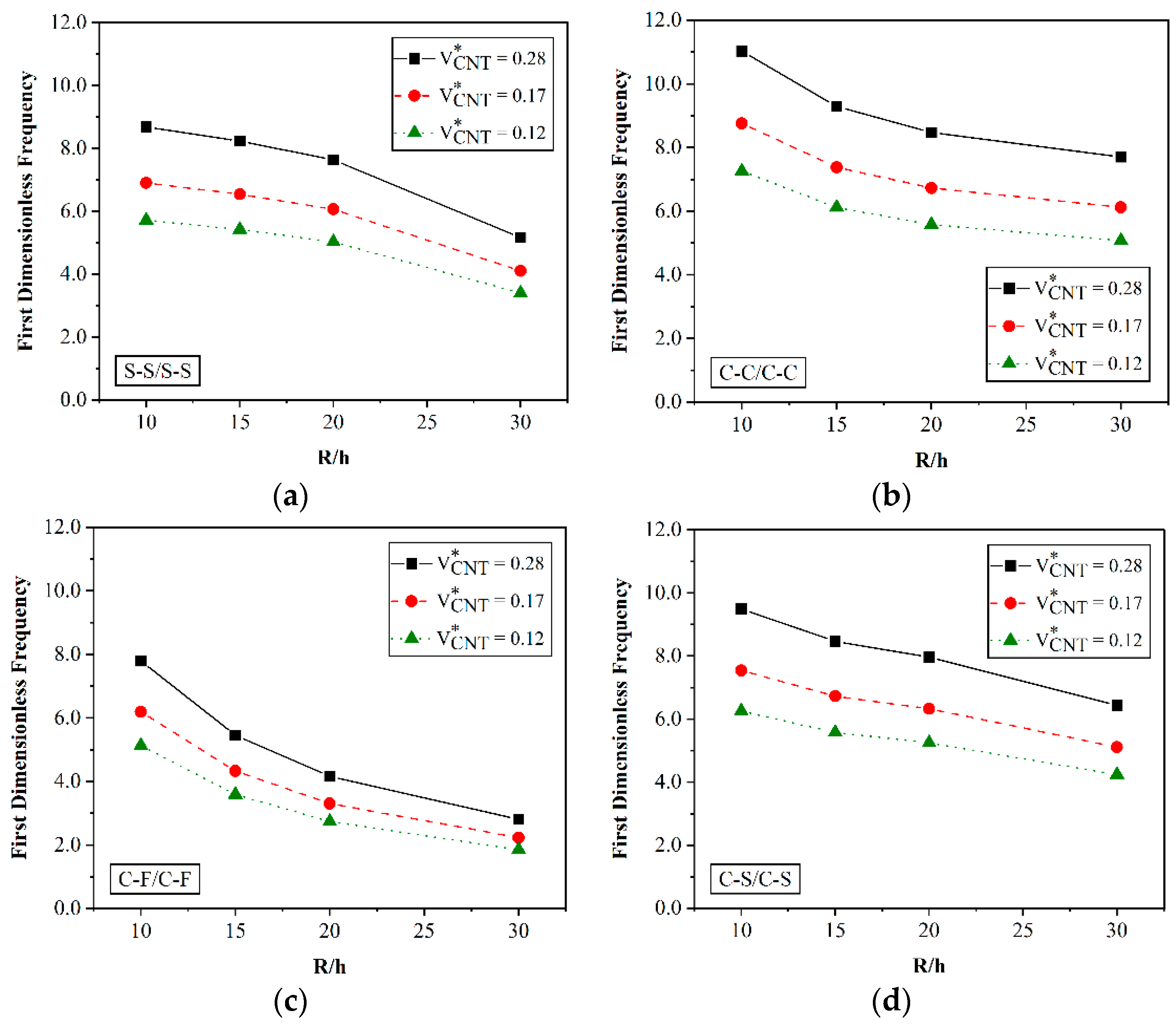
where the inertial quantity IBM of the beam is obtained as ρ d z . Figure 3 shows the effect of the rational radius-to-height quantity of the beam on the first dimensionless frequency of the coupled curved beams. To this end, four values of 10, 15, 20, and 30 are considered for R / h , while setting the stiffness factor equal to 100. The geometrical properties of the beams are θ = 45 ° , R1 = R2 = 10, and L 1 = L 1 = 2 R sin ( θ 2 ) . To investigate the effect of the CNT content, three different values of volume fraction are employed for CNTs, namely, V C N T = 0.12, 0.17, and 0.28. A uniform distribution of CNTs is employed throughout the beam for comparative purposes, under the same assumption of CNT volume fraction for each arm of the specimen. The frequency response is obtained for a system with S-S/S-S, C-C/C-C, C-S/C-S, and C-F/C-F boundary conditions. The results show that the frequency of the system decreases for an increased value of R / h . This is true for all boundary conditions and all CNT volume fractions. Also, for this example, we investigate the effect of the CNT volume on the frequency response of the system. Based on the results in Figure 3, a higher value of CNT volume fraction yields higher frequencies. For example, for a system with S-S/S-S boundary conditions and a fixed value of R / h = 10 , the first dimensionless frequency of the system increases from about six to nine by increasing V C N T from 0.12 to 0.28.
By comparing the rate of reduction of frequencies for an increased R/h, we can deduce that the CNTs volume fraction does not affect the reduction rate. In addition, the reduction rate for S-S/S-S, C-C/C-C, and C-S/C-S boundary conditions is nonlinear, whereas it becomes approximately linear for a C-F/C-F example. Such effect of BCs can be observed from a comparative evaluation of the plots in Figure 3. It can be also noticed that the frequency results associated with clamped boundary conditions are higher compared to other boundary conditions, in the following decreasing order: C-C/C-C > C-S/C-S > S-S/S-S > C-F/C-F.
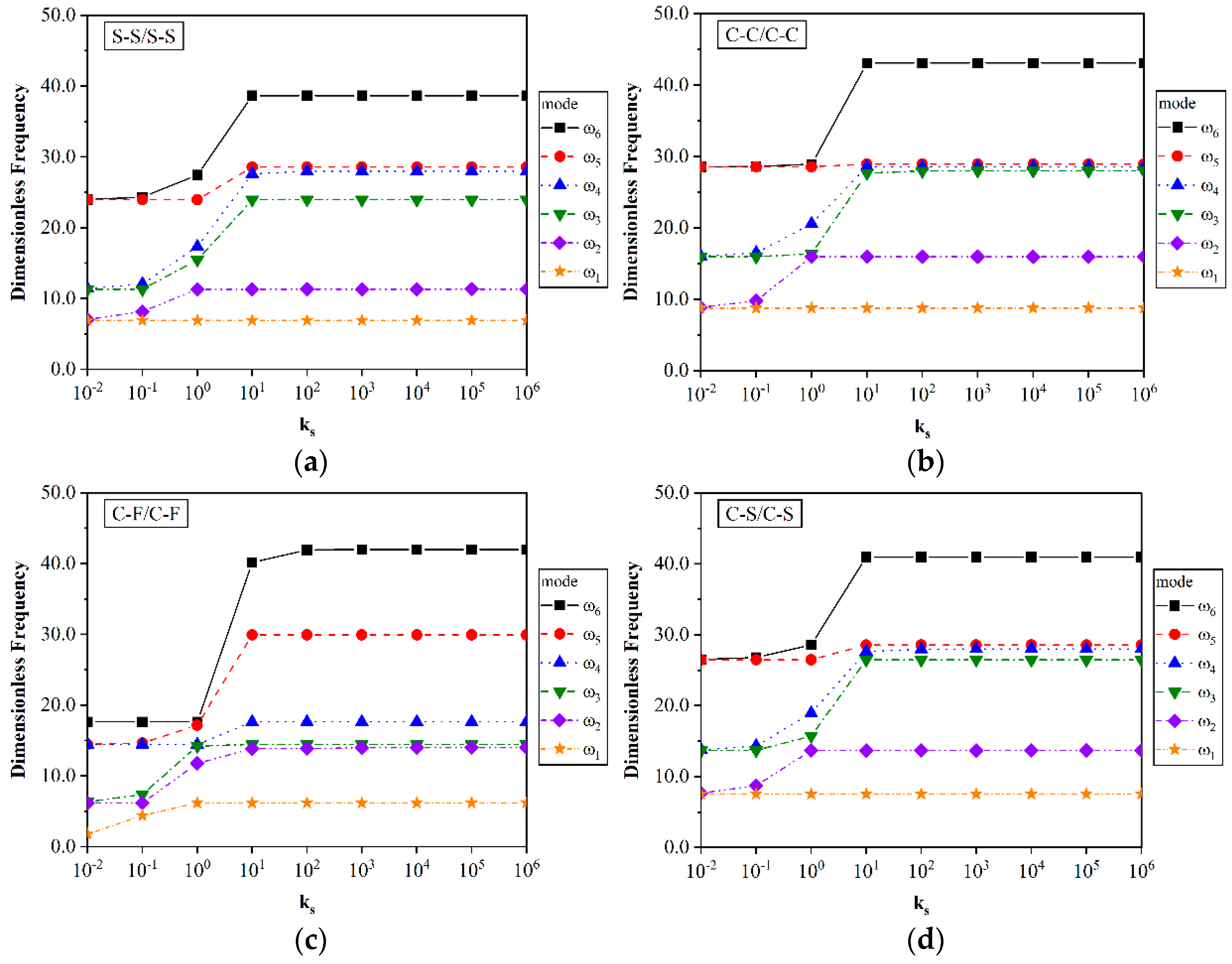
Figure 4 shows the effect of the interfacial stiffness on the first six frequencies of the system, here defined by means of the coefficient ABM which is obtained from the matrix properties. Nine different values are here considered as the stiffness factor, from 0.01 up to 106, whereas the CNTs volume fraction is assumed equal to 0.17 for a uniform distribution of CNTs. The geometry of beams is kept the same as in previous example, while assuming R/h is equal to 10. As already commented in the previous example, the higher values of frequencies are related to the system with C-C/C-C boundary conditions. For all boundary conditions, except C-F/C-F, the stiffness of the interfacial springs does not affect the first dimensionless frequency of system. Such sensitivity becomes more evident for higher modes of frequencies. The frequencies of the system increased for an increased interfacial stiffness up to a certain value of k s , above which frequencies remain constant. From this figure, it seems that the effect of the interfacial stiffness on the frequency response has a direct relationship with boundary conditions and mode frequency.
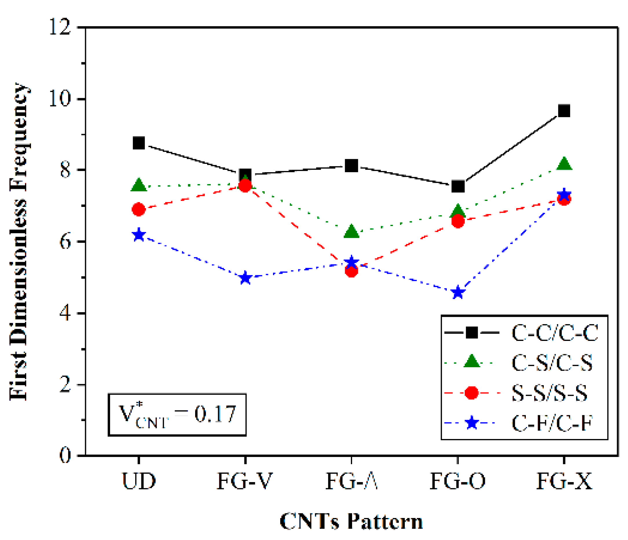
Figure 5 shows the effect of the CNTs pattern on the first mode frequency of the system, with the same geometry discussed before, and for an interfacial stiffness equal to 100. The volume of CNTs is 0.17 and CNTs are assumed to be distributed linearly in the same pattern in both beams (UD). Based on this figure, the effect of the distribution pattern is related to the boundary condition of the system. In all BCs, except for S-S/S-S, the highest value of the first dimensionless frequency is associated with the FG-X pattern. The lowest values of frequencies are associated with the Λ distribution (for S-S/S-S and C-S/C-S boundary conditions), and to circular CNTs distribution (for C-C/C-C or C-F/C-F boundary conditions). Based on a comparative evaluation of the frequencies, we get the following sequencies of frequency for each selected boundary condition and different distribution patterns of the reinforcement phase:
For a C-C/C-C system: FG-X > UD > FG-Λ > FG-V > FG-O,
For a C-S/C-S system: FG-X > UD ≈ FG-V > FG-O > FG-Λ,
For a S-S/S-S system: FG-V > UD > FG-X > FG-O > FG-Λ,
For a C-F/C-F system: FG-X > UD > FG-Λ > FG-V> FG-O.
Furthermore, for V and O distribution patterns of CNTs, the boundary conditions do not affect the first frequency of the system. This statement is true for C-C/C-C, S-S/S-S, and C-S/C-S boundary conditions.
Table 6 represent the frequency values for different CNTs volume fractions in the system. In this example, the CNT volume fraction at the top beam remains constant at 0.12, whereas V C N T at the bottom beam increases from 0.12 to 0.28. CNTs are uniformly distributed along the beams and the stiffness factor is equal to 100. The geometry of the beams is the same as in the previous example. Based on Table 6, the frequencies of the system slightly increase by increasing the CNT volume in the bottom beam. It also seems that there are no differences in the system frequencies for an increased number of CNTs at the top beam and bottom beam. In other words, it is not important which beam contains a higher volume of CNTs to increase the frequency response of the system.
Table 7 shows the frequency response of the system when only the bottom beam is reinforced by CNTs, and the top beam is made totally by PMMA. The volume fraction in the bottom beam varies from zero to 0.28 with an X-type functional graduation, where the condition V C N T = 0 corresponds to a pure matrix material. The geometrical properties of the beams are θ = 45 ° , R1 = R2 = 10, R/h = 10, and L 1 = L 2 = 2 R sin ( θ 2 ) , with a stiffness factor equal to 100. For an increased volume fraction of CNTs from zero to 0.12 in the bottom beam, the frequencies of the system increase for all boundary conditions, while keeping constant for volume fractions from 0.12 to 0.28. This means that the volume of CNTs as reinforcement at the bottom beams can affect the frequencies of the system when the top beam remains unreinforced. Based on the same table, there is no difference in the frequency system when the top or bottom beam is reinforced with CNTs.
Figure 6 shows the effect of curvature on the first dimensionless frequencies of the system. The CNTs volume fraction is 0.17 and distributed uniformly along the beams, under the same geometrical assumptions R1 = R2 = 10, R/h = 10, L 1 = L 2 = 2 R sin ( θ 2 ) , and k s equal to 100. In this example, six values of θ are employed, where the frequencies of the system are computed for three different types of boundary condition. Note that by increasing θ , the first frequency of the system decreases. For example, for C-C/C-C systems with a curvature factor of 15°, the frequency value is about thirty-nine and it tends to the unit value for θ = 180°.
In this section, we investigate the thermal-dependent vibration of the system. There are several studies in which the effect of temperature variation on the structural behavior has been investigated [79,80]. Thus far, the mechanical properties of SWCNTs (10,10) and PMMA have been represented at room temperature (300 °K). For other environmental temperatures, we consider the following expressions to define the thermal-dependent mechanical properties for SWCNTs:
E C N T 11 = 6.565376 1.76156 ( T T 0 ) + 1.13347 ( T T 0 ) 2 0.32260 ( T T 0 ) 3 + 0.03193 ( T T 0 ) 4 TPa E C N T 22 = 8.22710 2.19725 ( T T 0 ) + 1.41176 ( T T 0 ) 2 0.40125 ( T T 0 ) 3 + 0.03964 ( T T 0 ) 4 TPa G C N T 12 = 1.10442 + 1.88427 ( T T 0 ) 1.47623 ( T T 0 ) 2 + 0.49029 ( T T 0 ) 3 0.05829 ( T T 0 ) 4 TPa ρ C N T = 1400 k g c m 2   and   ν C N T = 0.175
where T and T0 represent the environment and room temperatures, respectively. The thermal-dependent Young’s modulus for PMMA can be obtained at any temperature by employing the following equation:
E M a t r i x ( T ) = { 3.52 0.0034 ( 300 + Δ T ) } GPa
The density and Poisson’s ratio in PMMA are also 1150 kg/m3 and 0.34, respectively, in thermal environment. Table 8 summarizes the variation of the mechanical properties for a SWCNT (10,10) and PMMA, with an overall monotonic decrease of all properties for an increased temperature.
It is worth observing that the mechanical properties of a pure PMMA matrix are more affected by temperature than the corresponding composite SWCNT (10,10). It is observed that the mechanical properties of PMMA and SWCNT decreases as the temperature increases. The following size-dependent parameters are here used in the rule of mixture to obtain the equivalent properties of beams in a thermal environment:
V C N T = 0.12 η 1 = 0.137 , η 2 = 1.022 , a n d η 3 = 0.715 V C N T = 0.17 η 1 = 0.142 , η 2 = 1.626 , a n d η 3 = 1.138 V C N T = 0.28 η 1 = 0.141 , η 2 = 1.585 , a n d η 3 = 1.109
In this section, we ignore the possible effect of αΔT in the theoretical formulation, where we compute the dimensionless frequencies as
ω ¯ = ω R I B M A B M
where IBM and ABM are computed at a room temperature (T = 300 °K). Table 9 presents the first ten dimensionless frequencies of the system made of a pure PMMA matrix. Results show that an increased environmental temperature does not affect the frequency response of S-S/S-S and C-C/C-C structures.
Table 10 summarizes the first six frequencies of the system at different temperatures. Five values of temperature (300°, 400°, 600°, 800°, and 1000 °K) are assumed to evaluate the thermal sensitivity of the vibration response. The fraction volume of CNTs in both beams kept equal to 0.12 under the assumption of uniform distribution for the reinforcement phase. The geometry properties of the beam are still assumed as R1 = R2 = 10, R/h = 10, and L 1 = L 2 = 2 R sin ( θ / 2 ) . The stiffness factor and the curvature angle are assumed equal to 100 and 45°, respectively. Despite the expected decrease in frequency for an increased environment temperature, we do not observe any meaningful variation in the vibration response of the selected system, since both curved beams are subjected to the similar temperature simultaneously, therefore, the frequency of the total system does not change.
In the last example, we study the vibration response of the structural system in thermal conditions, such that the temperature of one beam maintains constant to 300° and the temperature on the other beam varies from 300° to 1000°. In both beams, the CNT volume fraction is equal to 0.12 and a uniform distribution is assumed for the reinforcement phase. All geometrical properties of the beam, together with ks and θ, are assumed the same as in the previous example. In Table 11, we summarize the frequency response of the system. Results show that by increasing the bottom beam temperature from 300 to 1000, the frequencies of the system slightly decrease. For example, for a S-S/S-S system, when Tbottom = 400°, the first frequency is equal to 5.6356 and reduces to 5.5142 when Tbottom = 1000°. An increased temperature at the top beam induces a variation in the structural behavior, when the temperature of the bottom beam is kept constant to 300 °K. Based on Table 11, an increased temperature at the top beam yields an increased frequency response of the system, whereas the contrary occurs for an increased temperature at the bottom beam, which decreases the frequency response.
7. Conclusions

This paper has studied the vibrational behavior of nanocomposite coupled curved beams under a temperature variation, with an elastic interface modeled as an elastic distribution of elastic springs both in the normal and tangential direction. Each arm of the coupled specimen is made of a PMMA matrix reinforced with SWCNTs with a considerable and effective improvement in the vibrational response of the system. The equivalent temperature-dependent mechanical properties of the nanocomposite material have been obtained based on the well-known rule of mixture and approximate temperature-dependent formulation. Various distribution patterns of the reinforcement phase have been considered throughout the specimen, whose natural frequencies are determined by applying the GDQ technique as useful tool to discretize the governing differential equations of the problem, here determined according to a FSDT. A comparative analysis of the results against further theoretical predictions in the literature has confirmed the correctness and accuracy of the proposed procedure, where a large parametric investigation has evaluated the sensitivity of the vibrational response to different key input parameters, both in a geometric and mechanical sense—primarily, the curvature and the boundary conditions, along with the CNT distribution patterns, the interfacial stiffness, and the thermal dependence of the mechanical properties. It was observed that there is strong agreement between the obtained results and the responses from previous research (less than 5%). Some specific results can be pointed out:
  • The system frequency declines with an increased value of R/h. This holds true for all boundary conditions and various volume fractions of CNTs.
  • In all boundary conditions, except C-F/C-F, variations in the stiffness of the interfacial springs do not considerably influence the first dimensionless frequency of the system.
  • As the volume fraction of CNTs in the bottom beam rises from zero to 0.12, the system frequencies increase across all boundary conditions. However, they remain constant for volume fractions ranging from 0.12 to 0.28.
  • Elevating the temperature at the upper beam leads to an augmented frequency response of the system. Conversely, raising the temperature at the lower beam diminishes its frequency response.
These theoretical studies on the natural frequency response of FG-CNT coupled curved beams in thermal conditions have practical implications for optimizing structural design, material selection, and performance in aerospace, automotive, and related applications. The insights gained also contribute to vibration control, energy harvesting, and structural health monitoring.

Author Contributions

Conceptualization, F.T. and R.D.; Methodology, A.R.M., M.A.G., F.T. and R.D.; Validation, M.A.G., F.T. and R.D.; Formal analysis, A.R.M., M.A.G., F.T. and R.D.; Investigation, A.R.M. and R.D.; Data curation, F.T. and R.D.; Writing—original draft, A.R.M. and M.A.G.; Writing—review & editing, F.T. and R.D.; Supervision, F.T. and R.D. All authors have read and agreed to the published version of the manuscript.

Funding

This research received no external funding.

Data Availability Statement

The data presented in this study are available in article.

Conflicts of Interest

The authors declare no conflict of interest.

References

  1. Rezaiee-Pajand, M.; Rajabzadeh-Safaei, N. An explicit stiffness matrix for parabolic beam element. Lat. Am. J. Solids Struct. 2016, 13, 1782–1801. [Google Scholar] [CrossRef]
  2. Rezaiee-Pajand, M.; Rajabzadeh-Safaei, N.; Hozhabrossadati, S.M. On the damping influence on the dynamic analysis of functionally graded beams resting on elastic foundation by Green’s function method. Mech. Based Des. Struct. Mach. 2021, 51, 1666–1683. [Google Scholar] [CrossRef]
  3. Yue, X.G.; Sahmani, S.; Luo, H.; Safaei, B. Nonlocal strain gradient-based quasi-3D nonlinear dynamical stability behavior of agglomerated nanocomposite microbeams. Arch. Civ. Mech. Eng. 2023, 23, 1–18. [Google Scholar] [CrossRef]
  4. Pan, S.; Dai, Q.; Safaei, B.; Qin, Z.; Chu, F. Damping characteristics of carbon nanotube reinforced epoxy nanocomposite beams. Thin-Walled Struct. 2021, 166, 108127. [Google Scholar] [CrossRef]
  5. Seelig, J.M.; Hoppmann, W.H. Normal Mode Vibrations of Systems of Elastically Connected Parallel Bars. J. Acoust. Soc. Am. 1964, 36, 93–99. [Google Scholar] [CrossRef]
  6. Dublin, M.; Friedrich, H.R. Forced responses of two elastic beams interconnected by spring-damper systems. J. Aeronaut. Sci. 1956, 23, 824–829. [Google Scholar] [CrossRef]
  7. Simsek, M.; Cansiz, S. Dynamics of elastically connected double-functionally graded beam systems with different boundary conditions under action of a moving harmonic load. Compos. Struct. 2012, 94, 2861–2878. [Google Scholar] [CrossRef]
  8. Huang, J.; Liang, Z.; Zang, Q. Dynamics and swing control of double-pendulum bridge cranes with distributed-mass beams. Mech. Syst. Signal Process. 2015, 54–55, 357–366. [Google Scholar] [CrossRef]
  9. Li, Y.X.; Xiong, F.; Xie, L.Z.; Sun, L.Z. State-space method for dynamic responses of double beams with general viscoelastic interlayer. Compos. Struct. 2021, 268, 113979. [Google Scholar] [CrossRef]
  10. Li, Y.X.; Sun, L.Z. Transverse Vibration of an Undamped Elastically Connected Double-Beam System with Arbitrary Boundary Conditions. J. Eng. Mech. 2015, 142, 04015070. [Google Scholar] [CrossRef]
  11. Zhao, X.; Chen, B.; Ying-hui, L.; Zhu, W.D.; Nkiegaing, F.J.; Shao, Y. Forced vibration analysis of Timoshenko double-beam system under compressive axial load by means of Green’s functions. J. Sound Vib. 2019, 464, 115001. [Google Scholar] [CrossRef]
  12. Gu, L.; Qin, Z.; Chu, F. Analytical analysis of the thermal effect on vibrations of a damped Timoshenko beam. Mech. Syst. Signal Process. 2015, 60, 619–643. [Google Scholar] [CrossRef]
  13. Rezaiee-Pajand, M.; Rajabzadeh-Safaei, N. Static and dynamic analysis of circular beams using explicit stiffness matrix. Struct. Eng. Mech. 2016, 60, 111–130. [Google Scholar] [CrossRef]
  14. Dimitri, R.; Tornabene, F.; Reddy, J.N. Numerical study of the mixed-mode behavior of generally-shaped composite interfaces. Compos. Struct. 2020, 237, 111935. [Google Scholar] [CrossRef]
  15. Rezaiee-Pajand, M.; Rajabzadeh-Safaei, N. Stress-driven nonlinear behavior of curved nanobeams. Int. J. Eng. Sci. 2022, 178, 103724. [Google Scholar] [CrossRef]
  16. Sobhani, E.; Masoodi, A.R. Differential quadrature technique for frequencies of the coupled circular arch–arch beam bridge system. Mech. Adv. Mater. Struct. 2022, 30, 770–781. [Google Scholar] [CrossRef]
  17. Tornabene, F.; Viscoti, M.; Dimitri, R. Static Analysis of Anisotropic Doubly-Curved Shell Subjected to Concentrated Loads Employing Higher Order Layer-Wise Theories. CMES-Comput. Model. Eng. Sci. 2023, 134, 1393–1468. [Google Scholar] [CrossRef]
  18. Tornabene, F.; Viscoti, M.; Dimitri, R. Free vibration analysis of laminated doubly-curved shells with arbitrary material orientation distribution employing higher order theories and differential quadrature method. Eng. Anal. Bound. Elem. 2023, 152, 397–445. [Google Scholar] [CrossRef]
  19. Tornabene, F.; Viscoti, M.; Dimitri, R.; Rosati, L. Dynamic analysis of anisotropic doubly-curved shells with general boundary conditions, variable thickness and arbitrary shape. Compos. Struct. 2023, 309, 116542. [Google Scholar] [CrossRef]
  20. Mathews, P. Vibrations of a beam on elastic foundation II. ZAMM-J. Appl. Math. Mech./Z. Für Angew. Math. Und Mech. 1959, 39, 13–19. [Google Scholar] [CrossRef]
  21. Mathews, P. Vibrations of a beam on elastic foundation. ZAMM-J. Appl. Math. Mech./Z. Für Angew. Math. Und Mech. 1958, 38, 105–115. [Google Scholar] [CrossRef]
  22. Eisenberger, M. Vibration frequencies for beams on variable one-and two-parameter elastic foundations. J. Sound Vib. 1994, 176, 577–584. [Google Scholar] [CrossRef]
  23. Li, Z.; Xu, Y.; Huang, D. Analytical solution for vibration of functionally graded beams with variable cross-sections resting on Pasternak elastic foundations. Int. J. Mech. Sci. 2021, 191, 106084. [Google Scholar] [CrossRef]
  24. Jena, S.K.; Chakraverty, S.; Malikan, M. Vibration and buckling characteristics of nonlocal beam placed in a magnetic field embedded in Winkler–Pasternak elastic foundation using a new refined beam theory: An analytical approach. Eur. Phys. J. Plus 2020, 135, 1–18. [Google Scholar] [CrossRef]
  25. Chaabane, L.A. Analytical study of bending and free vibration responses of functionally graded beams resting on elastic foundation. Struct. Eng. Mech. Int. J. 2019, 71, 185–196. [Google Scholar]
  26. Deng, H.; Cheng, W.; Zhao, S. Vibration and buckling analysis of double-functionally graded Timoshenko beam system on Winkler-Pasternak elastic foundation. Compos. Struct. 2017, 160, 152–168. [Google Scholar] [CrossRef]
  27. Batihan, A.Ç.; Kadioğlu, F.S. Vibration analysis of a cracked beam on an elastic foundation. Int. J. Struct. Stab. Dyn. 2016, 16, 1550006. [Google Scholar] [CrossRef]
  28. Shen, H.-S.; Xiang, Y. Nonlinear analysis of nanotube-reinforced composite beams resting on elastic foundations in thermal environments. Eng. Struct. 2013, 56, 698–708. [Google Scholar] [CrossRef]
  29. Yas, M.H.; Samadi, N. Free vibrations and buckling analysis of carbon nanotube-reinforced composite Timoshenko beams on elastic foundation. Int. J. Press. Vessel. Pip. 2012, 98, 119–128. [Google Scholar] [CrossRef]
  30. Babaei, H. Free vibration and snap-through instability of FG-CNTRC shallow arches supported on nonlinear elastic foundation. Appl. Math. Comput. 2022, 413, 126606. [Google Scholar] [CrossRef]
  31. Seelig, J.; Hoppmann, I. Impact on an Elastically Connected Double Beam System; Rensselaer Polytechnic Institute: Troy, NY, USA, 1963. [Google Scholar]
  32. Hamada, T.R.; Nakayama, H.; Hayashi, K. Free and forced vibrations of elastically connected double-beam systems. Bull. JSME 1983, 26, 1936–1942. [Google Scholar] [CrossRef]
  33. Rao, S. Natural vibrations of systems of elastically connected Timoshenko beams. J. Acoust. Soc. Am. 1974, 55, 1232–1237. [Google Scholar] [CrossRef]
  34. Vu, H.; Ordonez, A.; Karnopp, B. Vibration of a double-beam system. J. Sound Vib. 2000, 229, 807–822. [Google Scholar] [CrossRef]
  35. Oniszczuk, Z. Free transverse vibrations of elastically connected simply supported double-beam complex system. J. Sound Vib. 2000, 232, 387–403. [Google Scholar] [CrossRef]
  36. Fortney, P.J.; Shahrooz, B.M.; Rassati, G.A. The Next Generation of Coupling Beams. Compos. Constr. Steel Concrete V. 2016. [Google Scholar] [CrossRef]
  37. Han, F.; Dan, D.; Cheng, W. An exact solution for dynamic analysis of a complex double-beam system. Compos. Struct. 2018, 193, 295–305. [Google Scholar] [CrossRef]
  38. Han, F.; Dan, D.; Cheng, W. Exact dynamic characteristic analysis of a double-beam system interconnected by a viscoelastic layer. Compos. Part B Eng. 2019, 163, 272–281. [Google Scholar] [CrossRef]
  39. Fei, H.; Danhui, D.; Wei, C.; Jubao, Z. A novel analysis method for damping characteristic of a type of double-beam systems with viscoelastic layer. Appl. Math. Model. 2020, 80, 911–928. [Google Scholar] [CrossRef]
  40. Zhao, Z.; Qi, T.; Zhou, W.; Hui, D.; Xiao, C.; Qi, J.; Zheng, Z.; Zhao, Z. A review on the properties, reinforcing effects, and commercialization of nanomaterials for cement-based materials. Nanotechnol. Rev. 2020, 9, 303–322. [Google Scholar] [CrossRef]
  41. Utsev, T.; Tiza, T.M.; Mogbo, O.; Singh, S.K.; Chakravarti, A.; Shaik, N.; Singh, S.P. Application of nanomaterials in civil engineering. Mater. Today Proc. 2022, 62, 5140–5146. [Google Scholar] [CrossRef]
  42. Cwirzen, A. Introduction to concrete and nanomaterials in concrete applications. Carbon Nanotub. Carbon Nanofibers Concr.-Advant. Potential Risks 2021, 1–58. [Google Scholar]
  43. Tran, T.T.; Dinh, K.N.; Ismail, E. Dynamic response of FG-CNTRC beams subjected to a moving mass. Vietnam J. Sci. Technol. 2022, 60, 853–868. [Google Scholar]
  44. Wang, Y.; Zhang, Z.; Chen, J.; Fu, T. Low-velocity impact response of agglomerated FG-CNTRC beams with general boundary conditions using Gram–Schmidt–Ritz method. J. Braz. Soc. Mech. Sci. Eng. 2022, 44, 1–20. [Google Scholar] [CrossRef]
  45. Cho, J.; Kim, H. Numerical Optimization of CNT Distribution in Functionally Graded CNT-Reinforced Composite Beams. Polymers 2022, 14, 4418. [Google Scholar] [CrossRef] [PubMed]
  46. Garg, A.; Chalak, H.; Zenkour, A.; Belarbi, M.-O.; Sahoo, R. Bending and free vibration analysis of symmetric and unsymmetric functionally graded CNT reinforced sandwich beams containing softcore. Thin-Walled Struct. 2022, 170, 108626. [Google Scholar] [CrossRef]
  47. Kumar, P.; Kumar, A. Stability analysis of imperfect functionally graded CNTs reinforced curved beams. Mech. Based Des. Struct. Mach. 2022, 1–22. [Google Scholar] [CrossRef]
  48. Yang, Z.; Liu, A.; Lai, S.-K.; Safaei, B.; Lv, J.; Huang, Y.; Fu, J. Thermally induced instability on asymmetric buckling analysis of pinned-fixed FG-GPLRC arches. Eng. Struct. 2022, 250, 113243. [Google Scholar] [CrossRef]
  49. Pan, S.; Feng, J.; Safaei, B.; Qin, Z.; Chu, F.; Hui, D. A comparative experimental study on damping properties of epoxy nanocomposite beams reinforced with carbon nanotubes and graphene nanoplatelets. Nanotechnol. Rev. 2022, 11, 1658–1669. [Google Scholar] [CrossRef]
  50. Safaei, B.; Moradi-Dastjerdi, R.; Behdinan, K.; Qin, Z.; Chu, F. Thermoelastic behavior of sandwich plates with porous polymeric core and CNT clusters/polymer nanocomposite layers. Compos. Struct. 2019, 226, 111209. [Google Scholar] [CrossRef]
  51. Qin, Z.; Pang, X.; Safaei, B.; Chu, F. Free vibration analysis of rotating functionally graded CNT reinforced composite cylindrical shells with arbitrary boundary conditions. Compos. Struct. 2019, 220, 847–860. [Google Scholar] [CrossRef]
  52. Ong, O.Z.S.; Ghayesh, M.H.; Losic, D.; Amabili, M. Coupled dynamics of double beams reinforced with bidirectional functionally graded carbon nanotubes. Eng. Anal. Bound. Elem. 2022, 143, 263–282. [Google Scholar] [CrossRef]
  53. Zhao, J.-L.; Chen, X.; She, G.-L.; Jing, Y.; Bai, R.-Q.; Yi, J.; Pu, H.-Y.; Luo, J. Vibration characteristics of functionally graded carbon nanotube-reinforced composite double-beams in thermal environments. Steel Compos. Struct. 2022, 43, 797–808. [Google Scholar]
  54. Gibigaye, M.; Yabi, C.P.; Degan, G. Free vibration analysis of dowelled rectangular isotropic thin plate on a Modified Vlasov soil type by using discrete singular convolution method. Appl. Math. Model. 2018, 61, 618–633. [Google Scholar] [CrossRef]
  55. Akgöz, B.; Mercan, K.; Demir, Ç.; Civalek, Ö. Static analysis of beams on elastic foundation by the method of discrete singular convolution. Int. J. Eng. Appl. Sci. 2016, 8, 67–73. [Google Scholar] [CrossRef]
  56. Parida, S.; Mohanty, S.C. Free vibration and buckling analysis of functionally graded plates resting on elastic foundation using higher order theory. Int. J. Struct. Stab. Dyn. 2018, 18, 1850049. [Google Scholar] [CrossRef]
  57. Civalek, O. Discrete singular convolution method for the free vibration analysis of rotating shells with different material properties. Compos. Struct. 2017, 160, 267–279. [Google Scholar] [CrossRef]
  58. Ersoy, H.; Mercan, K.; Civalek, Ö. Frequencies of FGM shells and annular plates by the methods of discrete singular convolution and differential quadrature methods. Compos. Struct. 2018, 183, 7–20. [Google Scholar] [CrossRef]
  59. Mojiri, H.; Salami, S.J. Free vibration and dynamic transient response of functionally graded composite beams reinforced with graphene nanoplatelets (GPLs) resting on elastic foundation in thermal environment. Mech. Based Des. Struct. Mach. 2022, 50, 1872–1892. [Google Scholar] [CrossRef]
  60. Zhang, P.; Schiavone, P.; Qing, H. Stress-driven local/nonlocal mixture model for buckling and free vibration of FG sandwich Timoshenko beams resting on a nonlocal elastic foundation. Compos. Struct. 2022, 289, 115473. [Google Scholar] [CrossRef]
  61. Al-Shujairi, M.; Mollamahmutoğlu, Ç. Buckling and free vibration analysis of functionally graded sandwich micro-beams resting on elastic foundation by using nonlocal strain gradient theory in conjunction with higher order shear theories under thermal effect. Compos. Part B Eng. 2018, 154, 292–312. [Google Scholar] [CrossRef]
  62. Tang, Y.; Ding, Q. Nonlinear vibration analysis of a bi-directional functionally graded beam under hygro-thermal loads. Compos. Struct. 2019, 225, 111076. [Google Scholar] [CrossRef]
  63. Li, X.; Li, L.; Hu, Y.; Ding, Z.; Deng, W. Bending, buckling and vibration of axially functionally graded beams based on nonlocal strain gradient theory. Compos. Struct. 2017, 165, 250–265. [Google Scholar] [CrossRef]
  64. Abediokhchi, J.; Kouchakzadeh, M.A.; Shakouri, M. Buckling analysis of cross-ply laminated conical panels using GDQ method. Compos. Part B Eng. 2013, 55, 440–446. [Google Scholar] [CrossRef]
  65. Tang, H.; Li, L.; Hu, Y. Buckling analysis of two-directionally porous beam. Aerosp. Sci. Technol. 2018, 78, 471–479. [Google Scholar] [CrossRef]
  66. Tornabene, F.; Dimitri, R. A numerical study of the seismic response of arched and vaulted structures made of isotropic or composite materials. Eng. Struct. 2018, 159, 332–366. [Google Scholar] [CrossRef]
  67. Javani, M.; Kiani, Y.; Eslami, M.R. Application of generalized differential quadrature element method to free vibration of FG-GPLRC T-shaped plates. Eng. Struct. 2021, 242, 112510. [Google Scholar] [CrossRef]
  68. Gholami, R.; Ansari, R. Nonlinear harmonically excited vibration of third-order shear deformable functionally graded graphene platelet-reinforced composite rectangular plates. Eng. Struct. 2018, 156, 197–209. [Google Scholar] [CrossRef]
  69. Shin, Y.-J.; Kwon, K.-M.; Yun, J.-H. Vibration analysis of a circular arch with variable cross-section using differential transformation and generalized differential quadrature. J. Sound Vib. 2008, 309, 9–19. [Google Scholar] [CrossRef]
  70. Fariborz, J.; Batra, R. Free vibration of bi-directional functionally graded material circular beams using shear deformation theory employing logarithmic function of radius. Compos. Struct. 2019, 210, 217–230. [Google Scholar] [CrossRef]
  71. Babaei, H.; Kiani, Y.; Eslami, M.R. Large amplitude free vibration analysis of shear deformable FGM shallow arches on nonlinear elastic foundation. Thin-Walled Struct. 2019, 144, 106237. [Google Scholar] [CrossRef]
  72. Kolahi, M.R.S.; Moeinkhah, H.; Rahmani, H. Numerical study of the non-linear vibrations of electrically actuated curved micro-beams considering thermoelastic damping. Commun. Nonlinear Sci. Numer. Simul. 2021, 103, 106009. [Google Scholar] [CrossRef]
  73. Shu, C. Generalized Differential-Integral Quadrature and Application to the Simulation of Incompressible Viscous Flows including Parallel Computation. Ph.D. Thesis, University of Glasgow, Glasgow, UK, 1991. [Google Scholar]
  74. Shu, C. Differential Quadrature and Its Application in Engineering; Springer: Berlin, Germany, 2000. [Google Scholar]
  75. Elboughdiri, N.; Reddy, C.S.; Alshehri, A.; Eldin, S.M.; Muhammad, T.; Wakif, A. A passive control approach for simulating thermally enhanced Jeffery nanofluid flows nearby a sucked impermeable surface subjected to buoyancy and Lorentz forces. Case Stud. Therm. Eng. 2023, 47, 103106. [Google Scholar] [CrossRef]
  76. Wakif, A.; Shah, N.A. Hydrothermal and mass impacts of azimuthal and transverse components of Lorentz forces on reacting Von Kármán nanofluid flows considering zero mass flux and convective heating conditions. Waves Random Complex Media 2022, 1–22. [Google Scholar] [CrossRef]
  77. Ghandehari, M.A.; Masoodi, A.R.; Panda, S.K. Thermal frequency analysis of double CNT-reinforced polymeric straight beam. J. Vib. Eng. Technol. 2023, 1–17. [Google Scholar] [CrossRef]
  78. Ghandehari, M.A.; Masoodi, A.R. Employing GDQ method for exploring undamped vibrational performance of CNT-reinforced porous coupled curved beam. Adv. Nano Res. 2023, 15, 551–565. [Google Scholar]
  79. Elboughdiri, N.; Ghernaout, D.; Muhammad, T.; Alshehri, A.; Sadat, R.; Ali, M.R.; Wakif, A. Towards a novel EMHD dissipative stagnation point flow model for radiating copper-based ethylene glycol nanofluids: An unsteady two-dimensional homogeneous second-grade flow case study. Case Stud. Therm. Eng. 2023, 45, 102914. [Google Scholar] [CrossRef]
  80. Zhang, K.; Shah, N.A.; Alshehri, M.; Alkarni, S.; Wakif, A.; Eldin, S.M. Water thermal enhancement in a porous medium via a suspension of hybrid nanoparticles: MHD mixed convective Falkner’s-Skan flow case study. Case Stud. Therm. Eng. 2023, 47, 103062. [Google Scholar] [CrossRef]
Figure 1. A scheme of the coupled system, (a) general scheme, (b) simply supported (S-S/S-S) configuration of the coupled curved beam.
Applsci 14 00687 g001
Figure 2. Different types of CNTs patterns in the beam section.
Applsci 14 00687 g002
Figure 3. Effect of R/h on first dimensionless frequency of system in varied volume of CNTs and different boundary conditions: (a) S-S/S-S, (b) C-C/C-C, (c) C-F/C-F, (d) C-S/C-S.
Applsci 14 00687 g003
Figure 4. Effect of the interfacial stiffness on the first six dimensionless frequencies of the system with different boundary conditions: (a) S-S/S-S, (b) C-C/C-C, (c) C-F/C-F, (d) C-S/C-S.
Applsci 14 00687 g004
Figure 5. First dimensionless frequency of the system for different patterns and boundary conditions, for a fixed volume fraction of CNTs equal to 0.12.
Applsci 14 00687 g005
Figure 6. Effect of θ on the first dimensionless frequency of system in different boundary conditions.
Applsci 14 00687 g006
Table 1. Mathematical definition of different CNTs patterns throughout the thickness.
Pattern TypeDistribution Factor
UD V C N T
FG-V( 1 + 2 z h ) V C N T
FG-Λ( 1 2 z h ) V C N T
FG-O 2 ( 1 2 | z | h )   V C N T
FG-X( 4 | z | h ) V C N T
Table 2. Dimensionless frequency of the homogenous curved beam.
ModeS-SC-C
This StudyRef. [13]This StudyRef. [13]
129.275729.285036.704536.7160
233.299533.321042.265642.2780
367.113667.202082.236882.3610
479.957880.049084.494384.5650
5107.835108.169122.311122.722
Table 3. Natural frequencies of coupled homogenous curved beams.
ModeC-C/C-CC-S/C-SS-S/S-SC-F/C-F
This StudyRef. [16]This StudyRef. [16]This StudyRef. [16]This StudyRef. [16]
110.93110.9328.66248.66246.70196.70232.93782.9378
211.34211.3429.16849.16847.33457.33493.52713.5271
320.62020.62118.03118.03215.54515.5464.57574.5756
420.86020.86118.30418.30415.86015.86111.00311.003
537.38037.38233.30633.30629.52829.53011.42311.424
Table 4. Dimensionless frequency of CNT curved beam with S-S boundary condition (L/R = 0.2 and L/h = 25).
CNTs
Pattern
V C N T This StudyRef. [30]
ω1ω2ω3ω4ω5ω1ω2ω3
UD0.1233.091053.060895.5477137.195178.95531.637353.661794.5798
0.1739.751765.6635119.925173.818227.91238.085766.2890118.645
0.2849.318375.6428133.685189.651245.80847.613777.3944133.310
FG-O0.1231.147543.321783.5019124.939167.51029.808843.482779.4926
0.1737.303752.9235103.529156.791211.89135.807153.265799.2077
0.2846.469163.0713119.963177.582236.51945.004164.6479117.180
FG-X0.1234.499958.4039101.363142.768184.10033.109159.2156101.272
0.1741.523172.9407128.366182.309236.09739.929673.3581127.006
0.2851.270083.6055143.256200.258257.27849.552383.0986138.326
Table 5. Dimensionless frequency of CNT curved beam with S-S boundary condition on elastic foundation.
V C N T CNTs
Pattern
This StudyRef. [30]
ω1ω2ω1ω2
0.17FG-O20.932147.182521.480348.6612
FG-X28.273964.316227.017064.3032
Table 6. The first six dimensionless frequency of the system when the CNTs volume of one beam of system changed.
V C N T Modes
12345678910
V C N T in both beams is 0.12
0.127.257213.21723.1823.67823.95235.68446.19446.35248.47861.03
V C N T at the top side of both beams is 0.12 and varies at the bottom beam
0.178.045214.64423.4626.54628.23439.52646.42853.03856.24667.324
0.289.356216.97323.57430.79835.45645.70246.47860.97269.56470.608
V C N T at the bottom side of both beams is 0.12 and varies at the top beam
0.178.045214.64423.4626.54628.23439.52646.42853.03856.24667.324
0.289.356216.97323.57430.79835.45645.70246.47860.97269.56470.608
Table 7. Dimensionless frequency for system which one of beams is made by matrix and another beam reinforced by different volumes of CNTs.
V C N T Modes
12345678910
Totally Matrix Beam
01.19172.1683.81063.88943.92685.8487.58447.61967.94629.996
bottomTop Beam Made by pure Matrix
0.123.80445.21787.63069.625611.43915.21916.91319.02219.15620.510
0.173.80666.27447.640011.31111.67515.22419.02219.17319.50121.104
0.283.80827.55007.998811.41814.53215.22519.02219.20120.18622.138
topBottom Beam Made by pure Matrix
0.123.80445.21787.63069.625611.43915.21916.91319.02219.15620.510
0.173.80666.27447.640011.31111.67515.22419.02219.17319.50121.104
0.283.80827.55007.998811.41814.53215.22519.02219.20120.18622.138
Table 8. Properties of PMMA and SWCNT (10,10) at different temperatures.
TEMatrixE11E22G12
°KGPaTPaTPaTPa
3002.505.64667.0801.9445
4002.165.56796.98161.9704
6001.485.50626.90391.9578
8000.805.42536.80261.9813
10000.125.28146.62191.9454
Table 9. Effect of the environmental temperature on frequencies of S-S/S-S and C-C systems with beams made of pure PMMA matrix.
ModeS-S/S-SC-C/C-C
Temperature (°K)Temperature (°K)
30040060080010003004006008001000
10.92580.92590.92580.92580.92581.17331.17331.17331.17331.1733
21.51331.51331.51331.51331.51332.12762.12762.12762.12762.1276
33.19683.19683.19683.1973.19683.75663.75663.75663.75663.7566
43.75663.75663.75663.75663.75663.83383.83383.83383.83383.8338
53.83183.83183.83183.83163.83183.84763.84763.84763.84763.8476
65.14745.14745.14725.14725.14725.72325.72325.72325.72325.7232
77.18427.18447.18407.18407.18427.46207.46207.46207.46207.4620
87.51167.51167.51167.51147.51147.51167.51167.51167.51167.5116
97.59647.59667.59627.59627.59647.78447.78447.78447.78447.7844
109.40249.40289.40249.40249.40269.76629.76629.76629.76629.7662
Table 10. Effect of the environment temperature on the frequency response of the S-S and C-C system.
ModeS-S/S-SC-C/C-C
Temperature (°K)Temperature (°K)
30040060080010003004006008001000
15.63566.01207.19989.689224.6027.14587.62329.129412.28631.196
29.22009.835811.77915.85240.25012.97813.84516.58122.31456.656
319.49320.79424.90433.51485.09422.85024.37229.17839.23098.294
422.84824.37229.17639.22697.84023.33624.89629.81240.124101.87
523.32424.88229.79840.100101.8223.49025.05830.00840.384102.54
631.40833.50840.12654.000137.1134.96037.29444.66460.108141.58
743.85446.78256.02675.398140.4945.46648.50458.08678.170150.78
845.68848.73658.34078.414145.3845.69048.73858.34678.428152.62
946.25049.34059.09079.520158.2947.52450.69860.71481.708169.18
1057.44661.28473.39298.768191.2359.70663.69476.278102.65198.48
Table 11. Dimensionless frequency of the system in the condition that the bottom beam temperature increased.
BCsmodeTtop beam= 300 °KTbottom beam= 300 °K
Tbottom beam (°K)Ttop beam (°K)
30040060080010003004006008001000
S-S/S-S15.63565.61205.58785.55905.51425.63566.03767.26249.826825.168
29.22009.18129.14189.09449.02129.22009.877611.88116.07741.172
319.49319.41119.32719.22819.07219.49320.88425.12033.99087.022
422.84822.73422.58422.38022.03622.84824.45429.34039.51299.016
523.32423.24423.19423.16023.13223.32425.00630.14440.928105.02
631.40831.27631.14230.98230.73231.40833.64840.47454.764140.12
743.85443.66643.47243.22842.83043.85446.97856.49876.408140.61
845.68845.44445.12844.71044.05245.68848.88658.62678.936145.90
946.25046.11046.04045.99845.9646.2549.60659.83281.262159.43
1057.44657.20456.95856.6656.19857.44661.54474.024100.15193.62
C-C/C-C17.14587.1167.08547.04866.9927.14587.65569.208812.4631.912
212.97812.92412.86912.80112.69812.97813.90416.72522.62857.948
322.85022.73422.58822.38422.04222.85024.45629.34439.52499.452
423.33623.25623.20623.16822.98223.33625.0230.15840.944104.84
523.49023.3923.2923.17023.13823.49025.16430.27040.958105.16
634.96034.81434.66434.48434.20634.96037.45445.05260.954141.76
745.46645.18444.8344.38443.67645.46648.61058.25278.400151.48
845.69045.58445.53245.47045.34845.69049.03859.15880.308155.92
947.52447.32847.14246.93046.64447.52450.91861.26682.946170.71
1059.70659.45659.19858.88858.40859.70663.96476.938104.08200.04
Disclaimer/Publisher’s Note: The statements, opinions and data contained in all publications are solely those of the individual author(s) and contributor(s) and not of MDPI and/or the editor(s). MDPI and/or the editor(s) disclaim responsibility for any injury to people or property resulting from any ideas, methods, instructions or products referred to in the content.