Abstract
The root residual stress during gear machining has a significant impact on the bending fatigue performance of the gear. The process parameters of gear hobbing (hob speed, axial feed speed, and radial cutting depth) directly affect the residual stress of the tooth root. To investigate the relationship between the process parameters of hobbing and the residual stress of the tooth root respectively, an analysis of an orthogonal and single factor was conducted in the hobbing experiment, taking into account the interactions among factors, which revealed the influence rule and primary–secondary relationship of the process parameters on the residual stress of the tooth root. The importance coefficients of the process parameters on the residual stress of the tooth root were calculated using the Least Absolute Shrinkage and Selection Operator (LASSO) method. The results indicate that the residual tensile stress at the tooth root increases with an increase in the hob speed and axial feed speed within the selected range but decreases with an increase in the radial cutting depth. The influence of the process parameters on the residual stress of the tooth root can be ranked as follows: hob speed (importance coefficient 0.460), axial feed speed (importance coefficient 0.278), and radial cutting depth (importance coefficient 0.262). This research provides a basis for improving the residual stress of the tooth root and enhancing the anti-fatigue manufacturing of gears, thus holding significant research value.
1. Introduction
The gear is a crucial component in transmitting motion and power, and its performance directly impacts the service life, reliability, and overall performance of major equipment [1]. The manufacturing process for a high-performance gear formation is mainly divided into two main steps: semi-finishing gear machining and finishing gear grinding [2]. Hobbing, as the initial processing step from a blank tooth to a gear, plays a vital role in determining the quality and performance of the gear. Residual stress is a critical factor affecting gear performance. Residual tensile stress will promote crack initiation and reduce the bending fatigue strength of the tooth root, while residual compressive stress can enhance the bending fatigue strength of the tooth root by slowing down crack propagation [3]. Therefore, if the residual compressive stress could be either preset at the tooth root or reduced by improving the process parameters of hobbing, it would significantly contribute to increasing the bending fatigue life of the gear.
In recent years, there have been numerous studies conducted on the residual stress of the gear grinding process in gear finishing technology. Liang et al. [4] studied the distribution pattern of residual stress in the helical bevel gears of heavy vehicles under different grinding parameters and calculated the residual stress of helical bevel gear grinding based on the mechanothermal coupling finite element simulation method. The findings revealed that the convex surface of the gear, parallel to the grinding direction, exhibited the lowest residual compressive stress, and tensile stress occurred on the tooth surface, while compressive stress was observed on the subsurface during the grinding process. Wang et al. [5] proposed a calculation model for residual stress in spiral bevel gears based on generative grinding and discovered that different grinding parameters at each point on the spiral bevel gear, under the same grinding conditions (grinding speed, generative speed, grinding depth), affected the distribution of residual stress on the tooth surface. Yi et al. [6] adopted the thermo-elastoplastic coupling structural analysis method, considering the tangential grinding force and grinding parameters, to calculate the residual stress distribution caused by the movement of the heat source, and their results indicated that residual stress would be generated along the profile when the grinding temperature exceeded 300 °C. Wang et al. [7] established a model for the tooth surface of face gear grinding based on the machine tool structure and the meshing mechanism with a large radius disc wheel. The findings revealed that the residual stress in face gear grinding is influenced by the grinding contact width, grinding contact length, and the number of dynamic effective grinding edges. Yu et al. [8] proposed a method, based on motion analysis of form grinding and a thermodynamic coupling finite element simulation calculation, to calculate the residual stress on the tooth surface of spur gear form grinding and analyzed the correlation law between the grinding parameters and the residual stress. The results indicated that the grinding wheel feed depth increasing resulted in a decrease in residual tensile stress on the tooth surface during form grinding. Xiao et al. [9] established a grinding model considering the position of abrasive particles and analyzed the distribution of residual stress during grinding, finding that both feed speed and cutting depth had an impact on the profile and axial residual stress. It can be seen from the above that different grinding process parameters have different effects on the residual stress of the gear, and the process parameters are an effective method for controlling residual stress. The existing research results also show that appropriate residual stress can be obtained by selecting appropriate process parameters, so as to improve the fatigue life of parts [10]. In particular, improving the residual stress of parts through machining is an effective method for realizing anti-fatigue manufacturing [11].
In terms of the aspect of the first processing process of tooth making, several scholars have conducted research on the influence of machining parameters on surface residual stress. Gao et al. [12] studied the effect of machining parameters on the surface residual stress by establishing a simulation model of friction disk gear pinion shaping. After optimizing the machining parameters by this method, the residual compressive stress at the tooth base increased by 203.13%, which significantly improved the fatigue life of the friction disk gear. Zachert et al. [13] examined the tangential, radial, and axial residual stresses of large gears during milling through different processing parameters and revealed that milling speed, feed rate per tooth, and milling width all affected the residual stresses on gears. Ueda et al. [14] explored the residual stress in the tooth shape direction during ultra-high-speed hobbing, and the results indicated that when 800 m/min, the residual tensile stress increased with the cutting speed; nevertheless, when 1000 m/min, the residual compressive stress dominated and increased with the cutting speed. These findings demonstrate that process parameters significantly impact the residual stress of gears during the first machining process from the tooth embryo to the gear.
Analytical methods and finite element simulation methods are commonly used to study machining residual stress. However, these methods simplify the coupling factors of actual machining and cannot cover all the actual conditions, which will significantly impact the research results. Therefore, the most intuitive way to obtain real machining results is through the experimental method. Niu et al. [15] conducted a study on the influence of process parameters on machining residual stress using experimental methods and analyzed the formation law of machining residual stress. Wu et al. [16] investigated the impact of different process parameters on the residual stress of machining through the experimental method and analyzed the conditions for obtaining residual compressive stress. Wu et al. [17] studied the mapping relationship between process parameters and residual stress using experimental methods. These examples demonstrate that the test method has been widely utilized in examining the relationship between process parameters and residual stress.
In conclusion, existing research on residual stress in gears primarily focuses on the influence of grinding process parameters on the residual stress of the gear during the final machining and rarely considers the influence of process parameters on the residual stress in the first machining process of gear making. Therefore, it is crucial to investigate the influence of process parameters on the residual stress in the first process of tooth making. Gear hobbing is the first process of gear making, and the residual stress of the tooth root is the key factor affecting the performance of the gear. As a consequence, this paper aims to explore the influence rule, relationship, and interaction between gear hobbing process parameters and root residual stress through experimental analysis. The findings from this study will serve as a foundation for enhancing root residual stress and improving the manufacturing technology of gears to withstand fatigue.
2. Kinematic Relation of Gear Hobbing
Gear hobbing machining is based on the principle of a generating method, and the tooth shape is formed by the meshing movement between the hob and the workpiece. The gear hobbing movement is equivalent to the meshing movement of the gear pair with staggered axes, including the rotation of the hob and the generative motion of the workpiece. The principle diagram of gear hobbing is shown in Figure 1a [18]. Reference [19] clearly explains the spatial relative position and motion relationship between the hob and workpiece during hobbing machining, as shown in Figure 1. OhXhYhZh is the fixed coordinate system of the hob, which rotates continuously with the hob around the Xh axis during the machining process; O1X1Y1Z1 is the hob installation coordinate system, which rotates an installation angle around the Y2 axis relative to the tool frame coordinate system according to the gear helix angle and hob thread lift angle; O2X2Y2Z2 is the tool rest coordinate system, parallel to the table coordinate system O3X3Y3Z3, which is the stationary reference coordinate system of the hobs and workpieces, respectively; OgXgYgZg is the fixed coordinate system of workpieces, which rotates around the Zg axis with the hob linkage during the hobbing process [19].
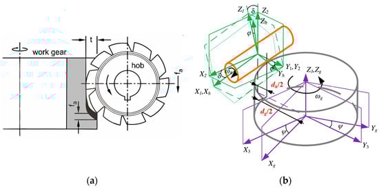
Figure 1.
(a) Principle diagram of hobbing [18]; (b) schematic diagram of spatial relative position and motion relationship between hob and gear [19,20].
The process parameters of gear hobbing can determine the relative motion relationship between the hob and gear during machining. The parameters are shown in Table 1, and the calculation formulas for each parameter are shown in Equations (1)–(5).

Table 1.
Relative position and motion parameters of hob and workpiece space.
is the pitch diameter of the hob, is the pitch diameter of the gear, and the radial installation distance of the hob is
In order to ensure that the hob helix direction coincides with the gear tooth direction, the hob installation angle is the algebraic difference between the gear helix angle and the hob helix lift angle :
The hob axial feed rate and feed speed are a pair of related process parameters. Determine the axial feed rate (mm/r) (the axial feed distance of the hob in one rotation of the table) during the process design, and then determine the axial feed speed (mm/min) according to the rotation speed of the hob and the table. N is the number of hob heads, and Z is the number of gear teeth.
As a function of the hob’s axial displacement and gear rotation phase angle with respect to hob rotation phase angle , the relation is shown in Equations (4) and (5). When the hob is rotating, the displacement is fed along the axis of the gear, and the “+” is taken when the process is straight-rolling, and the “−” is taken when the process is reverse-rolling. F is the axial feed speed. The workpiece that is relative to the hob synchronously rotates at angle, including the development angle and differential angle of the two components:
According to the analysis of the kinematic relation of gear hobbing, there are three types of working motions involved: the rotary motion of the hob, the feed motion of the hob along the shaft of the gear, and the rotary motion maintaining the meshing relationship between the gear and the hob. The above formula indicates that the rotary motion of the gear is dependent on the rotary motion of the hob, so it can be treated as a variable with the hob speed. Reference [21] analyzed the cutting conditions of a radial–axial feed strategy in gear hobbing machining, revealing that increasing the cutting times (radial cutting depth), cumulative cutting length, and average cutting length would result in a higher tool load. This also indicates that the depth of radial cutting in hobbing machining will also affect the machining quality of the gear. Therefore, it can be concluded that the hob speed, axial feed speed, and radial cutting depth are the primary parameters affecting the hobbing process.
Due to the gear transmission system tending to be lightweight, the bending strength of the tooth root becomes a critical constraint, and the fatigue fracture of the tooth root is actually more hazardous than the failure of the tooth surface. Additionally, the residual stress plays a significant role in affecting the bending fatigue performance of the tooth root. Therefore, the hobbing machining experiment focuses on investigating the impact of three process parameters (hob speed, axial feed speed, and radial cutting depth) on the residual stress of the tooth root.
3. Experimental Process and Method of Gear Hobbing
3.1. Experimental Conditions
The gear hobbing machine used in this study is a KE180-type gear hobbing machine from Kashifuji Company in Japan. The processing is carried out by means of sequential rolling. The machining test device and machining process are shown in Figure 2, the gear model and the processed gear are shown in Figure 3, and the basic parameters of the hob and gear are shown in Table 2. The gear material is 20CrMnTi, which has excellent high-temperature strength, prominent thermal stability, and remarkable fatigue resistance. The material is widely used in mechanical transmission gears in agriculture, automobile, marine, and aerospace industries [22,23], and the chemical composition [22] is shown in Table 3.
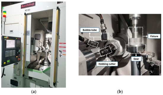
Figure 2.
Gear hobbing ((a) test device; (b) processing process).
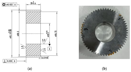
Figure 3.
Machining gear ((a) gear model; (b) finished gears).
Table 2.
Basic parameters of hob and gear.
Table 3.
Tempering chemical component of 20CrMnTi for test (mass score, %).
3.2. Test Scheme
According to the analysis of the kinematic relationship of hobbing machining in Section 2, the machining parameters (hob speed, axial feed speed, and radial cutting depth) were only changed during the experiment to explore the law of the influence of hobbing machining technology on the residual stress of the tooth root. Orthogonal test is a commonly used test optimization analysis method. The advantages of orthogonal experimental design include small experimental size and comprehensive experimental results, but the multi-level study on a single factor is not intuitive and comprehensive. Single-factor experimental design can compensate for the shortcomings of orthogonal experimental design, as the effect of different levels on a factor can be visually observed [24]. Therefore, for this experiment, both the single-factor experimental design and the orthogonal experimental design were used, with three factors and four levels in each case. The orthogonal test scheme is shown in Table 4, and the single-factor test scheme is shown in Table 5.
Table 4.
Orthogonal experiment scheme.
Table 5.
Single-factor experiment scheme.
3.3. Residual Stress Measurement
- (1)
- Measurement Position Determination
According to the analysis, when the load acts on the highest point of the meshing zone of a single pair of teeth, the bending stress generated by the tooth root is the largest. The dangerous cross-section of the bending stress of the tooth root can be determined by the 30° tangent method [25]. The dangerous cross-section of the bending stress of the tooth root is shown in Figure 4. The residual stress on the tooth root has a significant impact on the bending fatigue performance of the tooth root. When the gear is meshing, the superposition of the residual stress at the tooth root and the contact stress is more likely to produce bending fatigue [26]. Therefore, the residual stresses of the gear root were characterized by measuring the residual stresses of the contact point position on the gear with a 30° tangent.
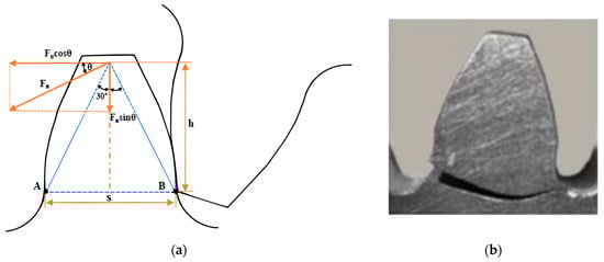
Figure 4.
Dangerous cross-section of tooth root bending stress ((a) schematic diagram; (b) actual picture) [25,26,27].
- (2)
- Residual Stress Measurement
Residual stress measurement methods usually include drilling method (destroying the workpiece), strain gauge method, X-ray method, and other technologies, among which X-ray diffraction method is the most convenient and reliable, and it does not undermine the workpiece residual stress measurement method. The measurement method used in this study is the isotropic fixed method [28].
In the study, DS-21L laboratory high-power X-ray residual stress tester was used to measure the residual stress at the root of the gear hobbing machining. The measuring instrument has automatic peak searching and positioning functions, which only need to fix the gear to prevent the gear from rolling during the measurement process. The measuring device and measuring scheme for residual stress at the root of gear are shown in Figure 5. The settings of important parameters for measuring residual stress at the root of the tooth are shown in Table 6. It should be noted that all gears in the machining test have undergone error detection and meet the machining accuracy requirements.
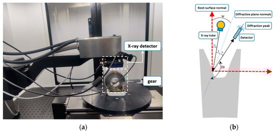
Figure 5.
Measuring device and measuring scheme for residual stress at the root of the tooth ((a) root residual stress measurement process; (b) schematic diagram of measuring residual stress at tooth root).
Since the surface of the root of the gear after hobbing is not smooth and flat, there are numerous hobbing marks [29,30], which make the measurement position inevitably affected by the machining tool marks. Therefore, in order to ensure the accuracy of the results, three positions of A, B, and C were selected for measurement along the outer circle of each gear at a distance of 120°, and the average value as the root residual stress of this gear was taken; considering the phenomenon of stress release, the middle position of each measurement position is selected as the measurement point. Reflection or absorption may occur during the measurement process, which may affect the measurement result. Therefore, absorbing materials were used at the measurement position to block the reflection, thereby eliminating the influence of reflection on the measurement result [31].
Table 6.
Settings of important parameters for measuring residual stress at root.
Table 6.
Settings of important parameters for measuring residual stress at root.
| Parameter Name | Parameter | Parameter Name | Parameter |
|---|---|---|---|
| Target material | Cr, Ka | Wave length | 2.291 |
| Tube voltage | 60 kV | Bragg cape | 156.41° |
| Tube current | 50 mA | Beta Angle number | 9 |
| Minimum spot size | 0.1 mm | Maximum beta sngle | 25° |
| X-ray elastic constant | S1 = 1.28 × 10⁻⁶ MPa−1 S2/2 = 5.92 × 10⁻⁶ MPa−1 | Executive standard | ASTM-E915-2010 EN15305-2008 [32] |
4. Results and Discussion
4.1. Orthogonal Test Analysis
Through the analyses of the above methods, the residual stress measurement results of the tooth root in the orthogonal test are shown in Table 7.
Table 7.
Orthogonality experiment results for residual stress at tooth root.
Before the scientific tests, four levels of hob speeds, axial feed speeds, and radial cutting depths were selected in advance, as shown in Table 8. The significant degree of influence of each gear hobbing parameter on the residual stress at the root of the tooth was compared by range R. The analysis results are shown in Table 9, and the main effect trend is shown in Figure 6. The greater the range R is, the more significant the influence of the process parameters on the residual stress of the tooth root is. It can be concluded that the importance of the process parameters on the residual stress of the tooth root is, successively, hob speed, axial feed speed, and radial cutting depth. In each process parameter range, the best process parameter combination is low hob speed, low axial feed speed, and small path cutting depth. Just as the results of the analysis of factors affecting the quality of gear hobbing in reference [33], it is believed that the process parameters having a greater impact on the quality of gear hobbing are hob speed, axial feed speed, and radial cutting depth.
Table 8.
Table of the different levels of orthogonal test factors.
Table 9.
Range analysis of residual stress of tooth root during hobbing.
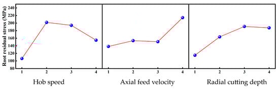
Figure 6.
Main effect of residual root stress.
In order to further quantify the importance of various process parameters on the residual root stress, the Least Absolute Shrinkage and Selection Operator (LASSO) is used to evaluate the process parameters. LASSO [34] is a statistical method for feature selection, which has the advantages of more efficient feature selection, better robustness, and stronger interpretation in data importance analysis. It is widely used and has significant effects in process parameter feature importance analysis, which could also provide the feature importance value. Therefore, LASSO is selected to analyze the importance of the process parameters of hobbing to the residual stress of the tooth root.
In the LASSO [35] algorithm, for the sample data set , the linear regression model is shown in Formula (6):
define the LASSO evaluation as Formula (7):
is the adjustment parameter, and is the least squares method, which through the control of the value achieves the objective function’s least squares results.
Restrict the condition function as a penalty function, and add the regular term to the objective function, as shown in Formula (8).
is the penalty coefficient (regularization coefficient); therefore, the weight meeting the objective function can reflect the importance of the feature:
As shown in Figure 7, the importance values of hob speed, axial feed speed, and radial cutting depth to the residual stress at the root of the tooth are, respectively, 0.460, 0.278, and 0.262, and the analysis results are consistent with the range analysis results.
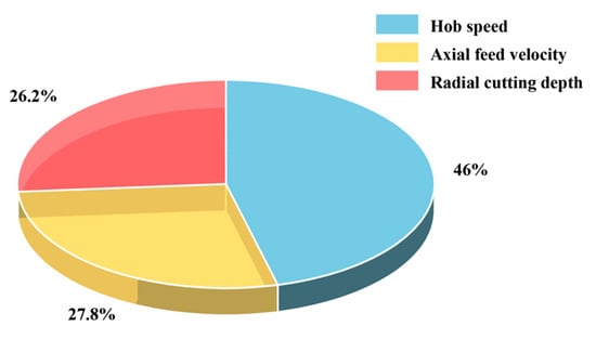
Figure 7.
Importance of gear hobbing machining parameters.
Since the measurement of residual stress in the tooth root is conducted after machining, the influence of the interaction between the process parameters must be considered. Based on the test results presented in Table 7, the influence of the interaction of gear hobbing process parameters on the residual stress at the root of the tooth is obtained, as shown in Figure 8. In the figure, the horizontal coordinate is the two-way combination of three process parameters: hob speed, axial feed speed, and radial cutting depth, and the vertical coordinate is the residual stress value of the tooth root. If the residual tensile stress that is generated during gear machining exceeds 150 MPa, it may affect the performance. Therefore, the value of the residual stress is divided from 150 MPa in this study, so that the influence of the process parameters on the residual stress of the tooth root can be more clearly distinguished.
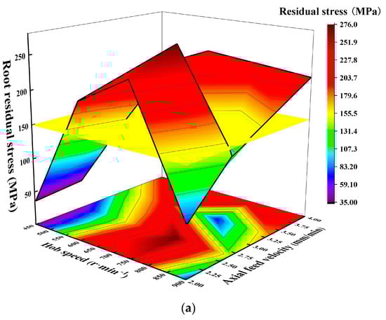
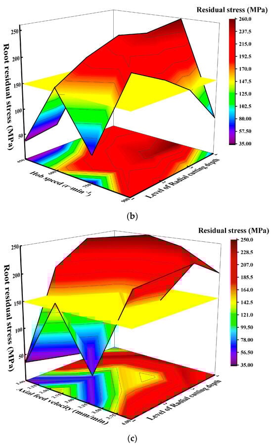
Figure 8.
(a) The effect of interaction of gear hobbing process parameters on residual root stress (interaction diagram of hob speed and axial feed velocity). (b) The effect of interaction of gear hobbing process parameters on residual root stress (interaction diagram of hob speed and radial cutting depth). (c) The effect of interaction of gear hobbing process parameters on residual root stress (interaction diagram of axial feed speed and radial cutting depth).
According to the findings presented in Figure 8a, under the interaction effect of the hob speed and axial feed speed on the residual stress of tooth root, the residual tensile stress is lowest in the range of 2–2.75 axial feed speed when the hob speed is low. With the increase in hob speed and axial feed speed, the residual tensile stress will increase. The reason is that the increase in hob speed and axial feed speed will elevate the cutting force and the cutting temperature, resulting in the phenomenon of regional heating concentration, which together lead to the increase in residual tensile stress. Additionally, it is evident from the results that the influence of the hob speed on the residual stress of the tooth root is obviously greater compared to the axial feed speed. The reason is that the increase in hob speed results in a rapid rise in cutting temperature, and the speed of the temperature increase brought on by the hob speed is much higher than the temperature increase rate brought on by the axial feed speed rate, which is the main source of the increase in cutting temperature. Consequently, the hob speed plays a more prominent role in determining the residual stress at the root of the teeth, aligning with the findings from the simulation of a high-speed hobbing process mentioned in reference [36].
According to the findings presented in Figure 8b, the interaction effect between the hob speed and radial cutting depth on tooth root residual stress is similar to that in Figure 8a. Under the condition of low hob speed, the residual tensile stress decreases with the decrease in radial cutting depth. When the hob speed is 750 r·min−1 and the radial cutting depth is maximum, the residual tensile stress is the highest. However, when the hob speed is 750 r·min−1 and the radial cutting depth is the smallest, there is also a small residual tensile stress, clearly indicating that the interaction effect of process parameters on the residual stress of the tooth root is prominent.
According to the findings presented in Figure 8c, under the interaction between the axial feed speed and the radial cutting depth on the residual stress at the root of the tooth, when the axial feed speed is slower than 3.5 mm/min, the residual tensile stress decreases with the decrease in radial cutting depth. The size of the axial feed speed is directly related to the cutting area and chip thickness, which will affect the cutting temperature and the machining quality of hobbing. According to the simulation in reference [36], when the axial feed speed increases, the cutting temperature does not increase obviously, which leads to a lower residual tensile stress. Furthermore, the radial cutting depth also has a certain influence on the cutting force and cutting temperature. A smaller cutting depth will increase the horizontal radial feed times, resulting in the accumulation of residual stress. As a consequence, it can be concluded that the axial feed speed plays a dominant role when the axial feed speed is slower than 3.5 mm/min and the radial cutting depth is smaller.
4.2. Single-Factor Experimental Analysis
Through the measurement of the above methods, the measurement results for the root residual stress of the single factor test are shown in Table 10.
Table 10.
Single-factor experiment results for residual stress at tooth root.
In order to further research the influence of each process parameter on the residual stress of the tooth root, a single-factor experiment was carried out. The influence trends of the hob speed, axial feed speed, and radial cutting depth on the residual stress at the root are shown in Figure 9. According to the findings presented in Figure 9a, with the increase in the hob speed, the residual stress value of the tooth root gradually increases, indicating that the residual tensile stress increases. With the increase in the hob speed, there will be more heat generated in the cutting zone, resulting in more drastic chip deformation and an increased chip compression ratio. Additionally, the chip temperature is significantly higher than the temperature of the corresponding separation position on the gear, which is due to the large deformation of the workpiece material and the great friction between the hob and the gear in the second deformation area, which is called the greatest heat concentration area [20]. The temperature variation in the cutting area affects the bond between the chip and the gear, with a higher temperature facilitating stronger bonding. Therefore, with the hob speed increases, the chip with a high heat load separates from the gear, leading to a rise in residual tensile stress on the gear surface.
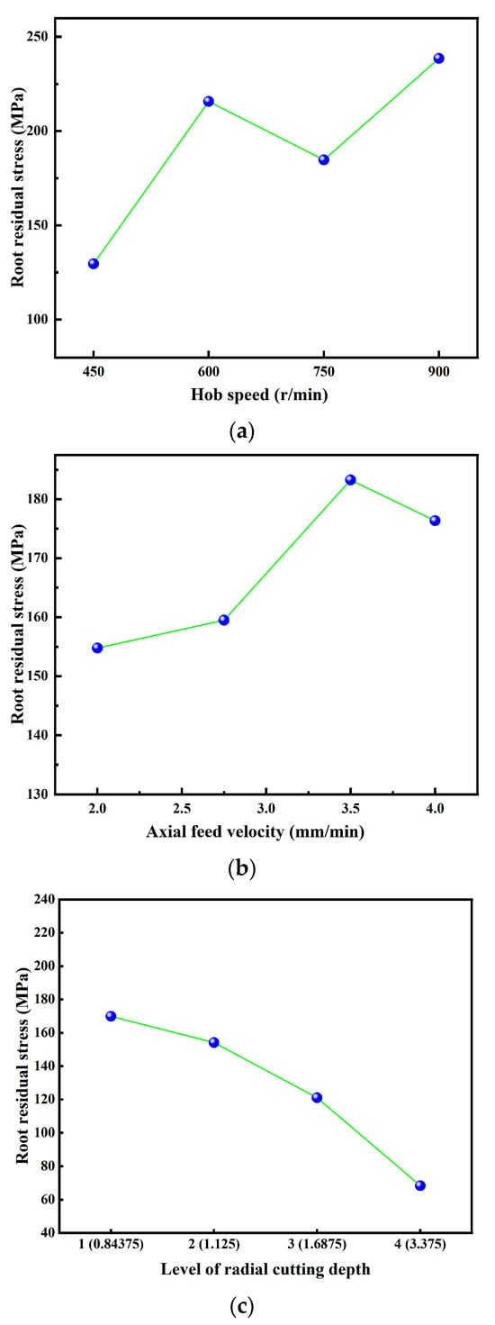
Figure 9.
(a) Single-factor test results of gear hobbing (effect of hob speed on residual stress at tooth root). (b) Single-factor test results of gear hobbing (effect of axial feed velocity on residual stress at tooth root). (c) Single-factor test results of gear hobbing (effect of radial cutting depth on root residual stress).
According to the findings presented in Figure 9b, with the increase in the hob axial feed speed, the residual stress value of the tooth root gradually increases, indicating the residual tensile stress increases, but the overall range is between 150 and 190 MPa. The main reason for this phenomenon is that when the axial feed speed increases, the volume of material that is cut by the cutter teeth per unit of time will increase, resulting in a gradual rise in the cutting force and cutting temperature, which jointly increase the force and cutting temperature. Moreover, the dominant factor in this increase is the cutting temperature. It is noteworthy that the range of variation in residual stress is relatively small, which is due to the axial feed speed having a lesser impact on the cutting stress. It has been proven by finite element simulation in reference that the effect of the axial feed speed on the cutting stress is not obvious [37], which explains the small variation range of the residual stress in this experiment.
According to the findings presented in Figure 9c, with the gradual increase in the radial cutting depth, the residual stress value of the tooth root gradually decreases, indicating that the residual tensile stress decreases. The increase in the radial cutting depth corresponds to a decrease in horizontal feed times, which in turn reduces the cumulative cutting length and load, resulting in a reduction in residual stress [21]. Liu et al. [38] support that in multiple cuts, the previous cuts usually produce accumulated strain/stress and temperature on the surface of the part, which will be carried to the subsequent cutting or final cutting and continue to affect the cutting force, process temperature, and deformation zone, ultimately impacting the final residual stress on the part. Ma et al. [39] further emphasize that the final residual stress is affected by the processing history. Li et al. [40] demonstrate that the depth of each cut also affects the distribution of residual stress. Therefore, with the increase in the radial cutting depth in the process of hobbing, the horizontal feed times will be decreased, which will reduce the accumulation of residual stress at the root of the tooth during the machining process, resulting in a lowering of the residual tensile stress.
5. Conclusions
In this paper, the effect of hobbing process parameters (hob speed, axial feed speed, and radial cutting depth) on the residual stress of the tooth root was researched by an orthogonal test and a single-factor test. Based on the above analysis results, the following conclusions were drawn:
- The process parameters of hobbing have a significant influence on the residual stress of the root, and the importance is successively given to the hob speed, axial feed speed, and radial cutting depth. In each process parameter range, the best process parameter combination is low hob speed, low axial feed speed, small path cutting depth.
- The influence of the hob speed on the residual stress of the tooth root is the greatest. According to the LASSO feature importance analysis, the respective importance values assigned to the hob speed, axial feed speed, and radial cutting depth in relation to the residual stress of the tooth root are 0.460, 0.278, and 0.262, which are consistent with the range analysis results.
- Under the cutting conditions of the experiment, the residual stress of the tooth root was measured as residual tensile stress. According to the analysis of the single-factor experiment, with the increase in the hob speed and axial feed speed, the residual tensile stress of the tooth root shows an increasing trend. With the increase in the radial cutting depth, the residual tensile stress at the tooth root exhibits a decreasing trend.
- If the residual compressive stress is to be obtained, the process parameters of hobbing should be optimized. It is necessary to replace the empirical method of process parameter selection with calculation algorithm.
Author Contributions
Conceptualization, Y.W. and H.X.; methodology, Y.W. and H.X.; software, H.X.; validation, Y.W. and H.X.; formal analysis, Y.W., H.X., H.S., G.W. and Z.W.; investigation, H.X., H.S., G.W. and Z.W.; resources, Y.W. and H.X.; data curation, Y.W. and H.X.; writing—original draft preparation, H.X.; writing—review and editing, Y.W.; visualization, Y.W. and H.X.; supervision, Y.W.; project administration, Y.W.; funding acquisition, Y.W. All authors have read and agreed to the published version of the manuscript.
Funding
This research was funded by National Defense Basic Scientific Research program of China, grant number JCKY2019427D002.
Institutional Review Board Statement
Not applicable.
Informed Consent Statement
Not applicable.
Data Availability Statement
Data are contained within the article.
Conflicts of Interest
The authors declare no conflicts of interest.
References
- Liu, H.; Zhang, B.; Zhu, C.; Wei, P. State of Art of Gear Contact Fatigue Theories. J. Mech. Eng. 2022, 58, 95–120. [Google Scholar]
- Sun, S.L.; Wang, S.L.; Wang, Y.W.; Lim, T.C.; Yang, Y. Prediction and optimization of hobbing gear geometric deviations. Mech. Mach. Theory 2018, 120, 288–301. [Google Scholar] [CrossRef]
- Ulutan, D.; Ozel, T. Machining induced surface integrity in titanium and nickel alloys: A review. Int. J. Mach. Tools Manuf. 2011, 51, 250–280. [Google Scholar] [CrossRef]
- Liang, Z.; Huang, D.; Zhou, T.; Li, H.; Liu, X.; Wang, X. Distribution Characteristic and Simulation Analysis on Grinding Residual Stress of Spiral Bevel Gears. J. Mech. Eng. 2018, 54, 183–190. [Google Scholar] [CrossRef]
- Wang, Y.Z.; Zhang, W.; Liu, Y. Analysis model for surface residual stress distribution of spiral bevel gear by generating grinding. Mech. Mach. Theory 2018, 130, 477–490. [Google Scholar] [CrossRef]
- Yi, J.; Jin, T.; Deng, Z.H.; Zhou, W. Estimation of residual stresses in gear form grinding using finite element analysis and experimental study based on grinding force and heat flux distribution models. Int. J. Adv. Manuf. Technol. 2019, 104, 849–866. [Google Scholar] [CrossRef]
- Wang, Y.Z.; Chu, X.M.; Huang, Y.Z.; Su, G.Y.; Liu, D.W. Surface residual stress distribution for face gear under grinding with a long-radius disk wheel. Int. J. Mech. Sci. 2019, 159, 260–266. [Google Scholar] [CrossRef]
- Yu, S.; Wen, J.; Tang, J.Y. Calculation and experimental verification of residual stress on tooth surface of spur gear form grinding. J. Mech. Transm. 2020, 44, 73–77. [Google Scholar]
- Xiao, Y.L.; Wang, S.L.; Ma, C.; Wang, S.B.; Yi, L.L.; Xia, C.J.; Dong, J.P. Measurement and modeling methods of grinding-induced residual stress distribution of gear tooth flank. Int. J. Adv. Manuf. Technol. 2021, 115, 3933–3944. [Google Scholar] [CrossRef]
- Zhou, J.Z.; Huang, S.; Zuo, L.D.; Meng, X.K.; Sheng, J.; Tian, Q.; Han, Y.H.; Zhu, W.L. Effects of laser peening on residual stresses and fatigue crack growth properties of Ti-6Al-4V titanium alloy. Opt. Lasers Eng. 2014, 52, 189–194. [Google Scholar] [CrossRef]
- Jiao, F.; Niu, Y.; Zhao, B. Research Progress of Residual Stress in Milling of Difficult-to-machine Materials. Surf. Technol. 2017, 46, 267–273. [Google Scholar]
- Gao, H.J.; Li, X.; Wu, Q.; Zhang, W.H.; Dai, G.W.; Zhang, G.H. The optimization of friction disc gear-shaping process aiming at residual stress and machining deformation. Rev. Adv. Mater. Sci. 2021, 60, 921–935. [Google Scholar] [CrossRef]
- Christoph, Z.; René, G.; Daniel, S.; Jens, B.; Thomas, B. Evaluation of the influence of different milling parameters and tool wear on the rim zone of a 5-axis milled large gear. Procedia CIRP 2022, 108, 43–48. [Google Scholar] [CrossRef]
- Ueda, Y.; Sakurai, N.; Takagi, T.; Ishizu, K.; Yan, J.W. Exploratory investigation of chip formation and surface integrity in ultra-high-speed gear hobbing. Cirp Ann.-Manuf. Technol. 2022, 71, 89–92. [Google Scholar] [CrossRef]
- Niu, Y.; Jiao, F.; Zhao, B.; Tong, J. Experiment of Machining Induced Residual Stress in Longitudinal Torsional Ultrasonic Assisted Milling of Ti-6Al-4V. Surf. Technol. 2019, 48, 41–51. [Google Scholar]
- Wu, Q.; Xie, D.J.; Si, Y.; Zhang, Y.D.; Li, L.; Zhao, Y.X. Simulation analysis and experimental study of milling surface residual stress of Ti-10V-2Fe-3Al. J. Manuf. Process. 2018, 32, 530–537. [Google Scholar] [CrossRef]
- Wu, S.; Liu, H.; Zhang, R.; Zhang, X.; Ge, Y. Prediction of Surface Integrity Parameters of Shot Peening Based on Orthogonal Experiment and Data-driven. Surf. Technol. 2021, 50, 86–95. [Google Scholar]
- Dong, X.; Liao, C.; Shin, Y.C.; Zhang, H.H. Machinability improvement of gear hobbing via process simulation and tool wear predictions. Int. J. Adv. Manuf. Technol. 2016, 86, 2771–2779. [Google Scholar] [CrossRef]
- Chen, Y.; Cao, H.; Li, X.; Chen, P. The Model of Spatial Forming with Multi-cutting-edge for Cylindrical Gear Hobbing and Its Application. J. Mech. Eng. 2016, 52, 176–183. [Google Scholar] [CrossRef]
- Yang, X.; Cao, H.J.; Chen, Y.P.; Zhu, L.B.; Li, B.J. An analytical model of chip heat-carrying capacity for high-speed dry hobbing based on 3D chip geometry. Int. J. Precis. Eng. Manuf. 2017, 18, 245–256. [Google Scholar] [CrossRef]
- Tross, N.; Löpenhaus, C.; Klocke, F. Analysis of the cutting conditions for radial-axial infeed strategies in gear hobbing. Procedia CIRP 2019, 79, 68–73. [Google Scholar] [CrossRef]
- Yang, L.J.; Wang, L.; Liu, Q.; Tian, X.L. Grinding performance of a new micro-crystalline corundum wheel when form-grinding automobile gears. Int. J. Adv. Manuf. Technol. 2018, 96, 857–870. [Google Scholar] [CrossRef]
- Winkler, K.J.; Schurer, S.; Tobie, T.; Stahl, K. Investigations on the tooth root bending strength and the fatigue fracture characteristics of case-carburized and shot-peened gears of different sizes. Proc. Inst. Mech. Eng. Part C J. Mech. Eng. Sci. 2019, 233, 7338–7349. [Google Scholar] [CrossRef]
- Singh, L.; Khan, R.A.; Aggarwal, M.L. Empirical modeling of shot peening parameters for welded austenitic stainless steel using grey relational analysis. J. Mech. Sci. Technol. 2012, 26, 1731–1739. [Google Scholar] [CrossRef]
- Sendlbeck, S.; Fromberger, M.; Otto, M.; Stahl, K. Effect of the ISO 6336-3:2019 Standard Update on the Specified Load Carrying Capacity Against Tooth Root Breakage of Involute Gears. Gear Technol. 2022, 39, 44–54. [Google Scholar]
- Conrado, E.; Gorla, C.; Davoli, P.; Boniardi, M. A comparison of bending fatigue strength of carburized and nitrided gears for industrial applications. Eng. Fail. Anal. 2017, 78, 41–54. [Google Scholar] [CrossRef]
- He, H.F.; Zhou, Y.; Liu, H.L.; Zhu, C.C.; Xiao, B.; Zhang, T.H. Study on gear bending fatigue considering gradient characteristics: Numerical analysis and experiments. Eng. Fract. Mech. 2023, 277, 19. [Google Scholar] [CrossRef]
- Guo, J.; Fu, H.; Pan, B.; Kang, R. Recent progress of residual stress measurement methods: A review. Chin. J. Aeronaut. 2021, 34, 54–78. [Google Scholar] [CrossRef]
- Klocke, F.; Gorgels, C.; Stuckenberg, A. Investigations on Surface Defects in Gear Hobbing. Procedia Eng. 2012, 19, 196–202. [Google Scholar] [CrossRef]
- Chen, Y.P.; Liu, X.; Yang, X.; Yang, Y. Investigation on Geometrical Morphology of Tooth Surface Finished by Green High-Speed Dry Hobbing for Gear Precision Machining. Int. J. Precis. Eng. Manuf.-Green Technol. 2023, 10, 1141–1154. [Google Scholar] [CrossRef]
- Liang, D.; Meng, S.; Chen, Y.; Hua, C.L. Experimental Analysis of Residual Stress and Bending Strength of Gear Tooth Surface after Shot Peening Treatment. Shock Vib. 2020, 2020, 10. [Google Scholar] [CrossRef]
- Shi, X.h.; Epco, T. Introduction to the Latest European and American Standard Test Methods for Residual Stress Measurement by X-ray Diffraction. Phys. Test. Chem. Anal. Part A Phys. Test. 2011, 47, 623. [Google Scholar]
- Wu, D.Y.; Yan, P.; Guo, Y.; Zhou, H.; Yi, R.Z. Helical Gear Machining Quality Estimation Based on Processing Parameters Importance Analysis. In Proceedings of the 2020 10th Institute of Electrical and Electronics Engineers International Conference on Cyber Technology in Automation, Control, and Intelligent Systems (CYBER), Xi’an, China, 10–14 October 2020; pp. 301–306. [Google Scholar]
- Li, F.W.; Lai, L.F.; Cui, S.G. On the Adversarial Robustness of LASSO Based Feature Selection. IEEE Trans. Signal Process. 2021, 69, 5555–5567. [Google Scholar] [CrossRef]
- Lockhart, R.; Taylor, J.; Tibshirani, R.J.; Tibshirani, R. A Significance Test for The LASSO. Ann. Stat. 2014, 42, 413–468. [Google Scholar] [CrossRef]
- Zhou, L.; Cao, H.; Chen, Y.; Yang, X. Process Simulation Model and Performance Analysis of High-speed Dry Gear Hobbing Based on Deform 3D. China Mech. Eng. 2015, 26, 2705–2710. [Google Scholar]
- Yang, X.; Cao, H.; Chen, Y.; Zhang, C.; Zhou, L. Whole Process Cutting Heat Transfer Model for High-speed Dry Hobbing. J. Mech. Eng. 2015, 51, 189–196. [Google Scholar] [CrossRef]
- Liu, Y.; Xu, D.D.; Agmell, M.; Ahadi, A.; Stahl, J.E.; Zhou, J.M. Investigation on residual stress evolution in nickel-based alloy affected by multiple cutting operations. J. Manuf. Process. 2021, 68, 818–833. [Google Scholar] [CrossRef]
- Ma, Y.; Zhang, J.F.; Feng, P.F.; Yu, D.W.; Xu, C. Study on the evolution of residual stress in successive machining process. Int. J. Adv. Manuf. Technol. 2018, 96, 1025–1034. [Google Scholar] [CrossRef]
- Li, B.Z.; Jiang, X.H.; Yang, J.G.; Liang, S.Y. Effects of depth of cut on the redistribution of residual stress and distortion during the milling of thin-walled part. J. Mater. Process. Technol. 2015, 216, 223–233. [Google Scholar] [CrossRef]
Disclaimer/Publisher’s Note: The statements, opinions and data contained in all publications are solely those of the individual author(s) and contributor(s) and not of MDPI and/or the editor(s). MDPI and/or the editor(s) disclaim responsibility for any injury to people or property resulting from any ideas, methods, instructions or products referred to in the content. |
© 2024 by the authors. Licensee MDPI, Basel, Switzerland. This article is an open access article distributed under the terms and conditions of the Creative Commons Attribution (CC BY) license (https://creativecommons.org/licenses/by/4.0/).