Abstract
The article is devoted to the study of ultrasonic agglomeration of PM 2.5 in homogeneous and inhomogeneous ultrasonic fields. The possibility of increasing the efficiency of ultrasonic agglomeration by initiating acoustic streams in a resonant inhomogeneous ultrasonic field is shown. A inhomogeneous ultrasonic field with zones of high and low sound pressure levels formed using a bending-oscillating disk transmitter made it possible to initiate acoustic vortex-type streaming that promotes the movement of particles into the nodal areas of a standing wave and between them. Due to the formation of a inhomogeneous ultrasonic field, the efficiency of particle collection is increased: for PM 2.5, the efficiency reaches 95%; PM 1.5—92%; PM 0.5—85%. The results were obtained under the following conditions: concentration 2 × 10⁻² g/m3, sound pressure level 165 dB, flow rate 6.2 m3/h. For comparison, when a homogeneous ultrasonic field is formed in the agglomeration chamber (under similar conditions), the efficiency of particle capture by inertial gas cleaning equipment does not exceed the following: for PM 2.5—89%; PM 1.5—85%; and PM 0.5—76%. The obtained research results made it possible to propose a design for an agglomeration chamber that can greatly increase the productivity of ultrasonic flow processing.
1. Introduction
The main efforts of environmental services are aimed at ensuring high-quality purification of ambient air polluted by industrial production and man-made natural phenomena. This is due to the fact that the presence and uncontrolled distribution of aerosols of various substances in the air has a negative impact on humans, flora and fauna [1,2]. It is generally accepted that the most dangerous particles are those measuring 2.5 microns or less, since the respiratory system introduces such particles into the bloodstream and accumulates toxic material in human organs [3,4]. The extremely dangerous nature of fine aerosols has been confirmed by numerous studies, in particular those conducted by L. Calderon-Garciduenas, A. Solt, C. Enriquez-Roldan and others. As a result of these studies, a connection has been established between long-term exposure to fine aerosols and sudden deaths of healthy children and young people [5]. The proof of such a correlation explains the exceptional importance of finding ways to protect people and developing systems for purifying air from fine aerosols.
All existing cleaning systems (separators) based on the inertial collection method practically do not capture particles smaller than 2.5 microns [6,7,8,9], and systems capable of capturing such particles (filters and electric precipitators) are characterized by low dust capacity or operate with the formation of very harmful particles. environment and human health nitrogen oxides and ozone.
The most effective way to solve the problem is the use of high-intensity ultrasonic vibrations, the effect of which on aerosols causes processes of convergence and agglomeration of small particles into large ones. This process is called ultrasonic agglomeration [10,11]. Fine particles combined due to ultrasonic action can subsequently be easily captured by conventional gas cleaning devices [12,13].
However, as follows from results of studies by various authors (J.A. Gallego-Juarez, R.R. Andres, C. Sheng), ultrasonic agglomeration loses its advantages when aggregating particles smaller than 2.5 μm for their subsequent removal, while providing a significant increase in efficiency (up to 99%) in the removal of particles larger than 2.5 μm, as per [14,15,16].
The reason for this lies in the very physical principles underlying the sonic agglomeration process. It is known that the impact of ultrasonic vibrations on gas media generates two types of nonlinear effects affecting dispersed particles in gases:
- (1)
- Effects arising due to the phenomena of momentum transfer of the gas phase between particles;
- (2)
- Effects arising due to oscillatory motions of solid particles of different sizes relative to each other.
The first group of effects contributes to the hydrodynamic mechanism (first described by W. Koenig in 1891) of particle agglomeration, when equivalent forces of hydrodynamic interaction (arising as a result of mutual distortion of flow fields around particles) bring particles closer to each other and promote their agglomeration. In this case, the probability of collision of particles is proportional not only to the interaction force of particles, but to their concentration, primarily (and, in fact, to the distance between particles) [17].
The second group of effects is realized in the orthokinetic mechanism (first described by O. Brandt, H. Freund, E. Hiedemann), which consists of the fact that the particle does not oscillate with the gas phase synchronously, while it slides relative to the gas phase and oscillates with a smaller amplitude of displacement than the gas itself. The sweep effect is related to the inertia of the particle [18]. The ratio of the particle oscillation amplitude to the gas oscillation amplitude is called the drag coefficient. The drag coefficient depends on the particle size, and particle collision occurs due to the fact that particles of different sizes oscillate with different amplitudes (with non-zero amplitude relative to each other) and randomly collide and aggregate. For fine particles smaller than 2.5 μm, the drag coefficient modulus is close to 1, i.e., all particles oscillate almost in-phase with approximately equal amplitude, regardless of the sound pressure value. Accordingly, the orthokinetic interaction is weakly realized particle [18].
In addition, for particles to aggregate, the distance between them should not exceed the displacement amplitude of gas molecules in the sound field. For these reasons, the low probability of particle collision, especially at low concentrations (large distances between particles) leads to the fact that, even at the maximum permissible sound pressure level (before the destruction of the formed agglomerates), increasing the efficiency of agglomeration of particles smaller than 2.5 μm due to ultrasonic vibrations becomes virtually impossible. For example, in [19] it is shown that ultrasonic coagulation studies were carried out under conditions of high mass concentration of particles in the range from 0.2 to 5 g/m3. Such conditions are typical during the production of any product and its capture in the form of highly dispersed particles. At the same time, due to ultrasonic exposure, the cleaning efficiency increased from 30–50% to only 40–85%.
However, research results indicate that at relatively low concentrations (less than 0.2 g/m3, which is typical for industrial emissions, for example at thermal power plants), the efficiency of agglomeration will be very low, the degree of agglomeration will not exceed 2–3.
Various agglomeration systems utilizing standing wave aerosol impacts are proposed to address this problem.
It is known that Gallego-Juárez et al. developed a semi-industrial pilot-scale system combining an electrostatic precipitator and an acoustic agglomeration chamber to remove submicron particles (average particle size 0.8 µm) from a flue gas flow [20]. In this system, four ultrasonic transducers were arranged at the bottom of the agglomeration chamber, and the standing wave sound field was generated perpendicular to the gas flow to ensure agglomeration. The disadvantage of this design is low efficiency at low concentration. This is due to the fact that during generation of the standing wave the particles almost do not interact with each other even within the node areas.
Miura et al. developed several types of airborne ultrasonic transducers that generate powerful sound waves in the air [21,22]. Among them is an ultrasonic radiator in which a rigid wall was attached around the circumference of a circular transversely vibrating plate. This ultrasonic radiator shapes an intense standing wave sound field into a cylindrical sealed space perpendicular to the plane of the circular transversely vibrating plate. Therefore, the fine particles can be retained in enclosed space in which the powerful sound field is formed. Using this sound wave agglomeration equipment, the effect of fine particle concentration on agglomeration was studied, and the agglomeration effect was higher at higher particle concentrations. However, ultrasonic wave agglomeration for PM 2.5 achieved an agglomeration efficiency of no more than 63%. This is due to large distances between particles, at which the ultrasonic interaction processes do not take place.
This determines the urgent need to find new ways to further increase the efficiency of ultrasonic agglomeration of particles smaller than 2.5 μm.
Understanding the actual mechanisms of ultrasonic agglomeration suggests that, if it is impossible to further increase the sound pressure level (the value of direct impact on the particles), the probability of collision of small particles can be increased by giving them additional movements that contribute to their collision and aggregation.
In [19,23], it was proposed to increase the efficiency of agglomeration by swirling the flow with dispersed particles at the entrance to the agglomeration chamber. Due to this, a swirling flow is created in the agglomeration chamber and the particles (under the influence of centrifugal forces) are pushed to the outer part of the vortex. As the authors state, an area of increased concentration is created there and this area is affected with maximum efficiency. This approach makes it possible to increase the efficiency of agglomeration; however, due to the small size of the particles and the high degree of their entrainment by the swirling flow, the action of centrifugal forces is not effective enough. Therefore, this approach does not allow efficient implementation of acoustic agglomeration.
Therefore, it is proposed additional impact on small particles in the ultrasonic field through the use utilization of secondary effects arising under certain conditions of generation of high-intensity ultrasound impact. One of such secondary intensifying effects is the so-called “ultrasonic wind”. This is a second-order effect due to momentum transfer, represented by the Reynolds voltage. Theoretical studies of acoustic flows are well developed [24,25] and carefully modeled [26,27].
However, when ultrasonic (US) impact is implemented in an open space or a long gas duct, the radiation pressure generated enables the particles to be moved only in one direction without significant increase in efficiency of interaction between particles [28]. For this reason, in order to increase the efficiency of small-particle interaction in the maximum ultrasonic field in terms of sound pressure level, it is essential to generate the motion of particles in different directions, so that their mutual movement and interaction is realized. In addition, it is required to increase the concentration of particles in certain areas by moving them to significantly increase the efficiency of particle agglomeration, especially at their low concentration [8,11,20,23,29].
This can be provided by generation of vortex flows, because only vortex flows will increase the efficiency of interaction (aggregation) of particles due to the following factors:
- Increasing the speed of mutual movement of particles of different sizes.
- Increasing duration of interaction of particles due to their confinement in vortex areas;
- Generating zones with increased concentration of particles.
There are known attempts to achieve this by initiating vortex acoustic flows near obstacles or reflectors. Such approaches can improve the efficiency of coagulation. But due to the fact that acoustic flows are not created in the entire volume of the agglomeration chamber, but in a small near-wall region, the maximum increase in efficiency is not ensured [30].
For this reason, this work proposes a new approach, which consists of creating in the entire volume of the agglomeration chamber a sequence of adjacently located elementary acoustic flows of the vortex type, corresponding in scale to the zones of pressure drop in the oscillatory process. This allows the volume of the agglomeration chamber to be filled as much as possible with vortex flows and increases the efficiency of agglomeration. Therefore, the research results presented below are focused on identification of conditions for generation of vortex flows in ultrasonic fields with the maximum sound pressure level of ultrasonic impact. Comparative studies of the process of agglomeration of particles with a size of 2.5 μm in the presence of vortex flows and without them allows to establish the actual values of increasing the efficiency of ultrasonic agglomeration due to vortex formation of gas-dispersion flow by acoustic streaming.
2. Materials and Methods
2.1. Test Bench
To study the agglomeration process of 2.5 μm particles and to conduct comparative studies in the presence of vortex flows and without them, a bench implementing ultrasonic agglomeration and subsequent capture of aggregated particles was used. The test bench consists of agglomeration chamber (Figure 1) and sequentially installed cyclone based on the design of VNIIOGAZ CN-15 with a capacity of 10 m3/h. The cyclone outlet tube is connected to the air handling unit.
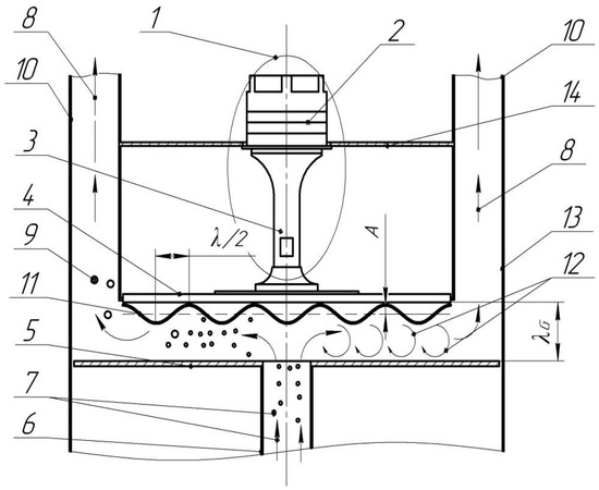
Figure 1.
Schematic diagram of the ultrasonic agglomeration chamber: 1—ultrasonic vibrating system; 2—piezoelectric transducer; 3—concentrator; 4—disk radiator; 5—reflector; 6—inlet tube; 7—polluted gas; 8—outgoing gas-dispersion flow (to cyclone); 9—aggregated particles; 10—outlet tubes; 11—amplitude distribution; 12—vortex flows; 13—housing; 14—radiator flange; λG—distance between radiator and reflector.
The developed and manufactured agglomeration chamber of the bench (RF Patent No. 2759506) is suitable for implementation of various conditions and modes of exposure to high-intensity ultrasonic vibrations due to the application of different types of ultrasonic transducers, and owing to the possible resonance amplification of vibrations by changing the distance between radiator and reflector [29].
Two ultrasonic oscillating systems (No. 1, Figure 1) with disk radiators (No. 4, Figure 1) of two different types creating uneven or uniform distribution of vibrations for ultrasonic impact with and without flow generation were used as a source of ultrasonic impact in the agglomeration chamber. A reflector (No. 5, Figure 1) with a centrally placed inlet tube (No. 6, Figure 1) is installed across the disk radiator.
The process of particle aggregation in the agglomeration chamber takes the following course. The gas flow enters the tube (No. 6, Figure 1) installed in the center of the reflector (No. 5, Figure 1). After that, the gas-dispersion flow spreads uniformly from the central area to the periphery. In the process of propagation, the flow is affected by ultrasonic vibrations generated between the surfaces of radiator (No. 4, Figure 1) and the reflector (No. 5, Figure 1). The gas flow (No. 8, Figure 1) and aggregated particles (No. 9, Figure 1) are discharged through outlet tubes (No. 10, Figure 1).
The design of the agglomeration chamber allows us to adjust the height of the reflector position to achieve fine-tuning of the resonance mode (standing wave mode in a gas medium). When the distance between the radiator and the reflector ensures the generation of a standing wave, the effectiveness of the treatment is increased by means of increasing the sound pressure level.
The test bench was equipped with measuring and auxiliary equipment. A noise meter Ecofizika-110A («OKTAVA-ElektronDizayn», Moscow, Russia), with microphone—VMK-401 («Vibropribor», Yaroslavl, Russia) and microphone preamplifier R200-27 («OKTAVA-ElektronDizayn», Moscow, Russia) was used to measure the main parameter (i.e., sound pressure level). The TIPAS-1 (IPCET SB RAS, Biysk, Russia) aerosol dispersion characteristics measuring instrument, which enables monitoring the aerosol parameters, was used to measure the dispersion properties of the aerosol. TIPAS-1 consists of two units:
- The first unit implements the optical method of small-angle scattering (radiator, reflector) and is designed to measure micron aerosol particle sizes and concentrations in the range of 1–100 µm and 0.009–8.0 g/m3;
- The second unit implements the optical spectral transparency method (radiator and reflector) and is designed to measure submicron aerosol particle sizes and concentrations in the range of 0.1–2 µm and 0.009–8.0 g/m3.
Sampling to determine the mass concentration of particles was carried out at the inlet of the agglomeration chamber and at the outlet of the cyclone. The dispersed particles were supplied by pneumatic atomizer (Patriot HVLP 1.8, China) of ejection type installed in front of the inlet of the agglomeration chamber.
A laser plane plotter is installed in the chamber to track particle trajectories (BOSCH GLL 2-20 G, China). The laser plane passes through the axis of symmetry of the radiator. The camera (high-speed camera “Videosprint” G4/NG, VIDEOSKAN, Moscow, Russia) is focused on the laser plane and enables video recording of the particles travelling between the radiator and the reflector. The directions of gas flows are determined indirectly by trajectories of light-scattering (tracer) particles. To determine particle trajectories, the “Trackpy” library (Python package for particle tracking, v.0.6.1) was used.
The amplitude of vibrations of the radiator surface was measured using a VM1-5 non-contact vibrometer based on the capacitive method. To measure the amplitude of oscillations on the radiating surface, a three-dimensional positioning system was used, on the carriage of which a meter sensor was installed.
2.2. Ultrasonic Transducers
Today, several approaches to generating inhomogeneous fields are known and can be applied in practice. They can be divided into two groups: the use of inhomogeneities in the medium in which acoustic vibrations propagate, and inhomogeneities in the distribution of vibrations of the ultrasonic radiator itself. An approach based on the use of inhomogeneities in the properties of the medium is described in [31]. The authors have developed a stochastic model that can generate the fluctuation part of the propagation field due to random changes in speed in the propagation medium. The main difficulty that arises in the practical implementation of this approach is the difficulty of determining the inhomogeneities of the environment and maintaining their long-term stability. However, this approach can be used in further research.
The second approach to generating inhomogeneous fields uses the homogeneity of oscillations of the radiators themselves [32,33]. The radiator in this case is a matrix of piezoelectric transducers. Such a radiator, due to the difference in phase and amplitude of oscillations, makes it possible to generate a non-uniform field. However, the power of the created acoustic fields turns out to be small. Therefore, we took this principle as a basis and developed more powerful ultrasonic radiators for generating uniform and non-uniform fields, described below.
Two ultrasonic radiators consisting of a piezoelectric Langevin transducer and a disk-shaped bending and oscillating radiator were used for the research. At the same time, due to excitation of oscillations on the non-basic mode, oscillation maxima and minima are generated on the frontal surface of the radiator, interchanging at a distance from each other corresponding to half the wavelength of bending oscillations in the radiator material [23,34]. To generate an inhomogeneous ultrasonic field and its impact on the gas-dispersion flow, a bending-oscillating disk radiator with a flat frontal surface (hereinafter referred to as the flat radiator) was used. In turn, to generate a homogeneous ultrasonic field, a radiator with phase-equalizing collars with a height equal to half of the wavelength in the gas (hereinafter referred to as a step-function radiator) was used.
Figure 2 shows diagrams explaining the principle of operation of the two types of disk radiators used for comparative studies. The radiators were made with equal-sized radiation surfaces and with the test frequencies as close to each other as possible.
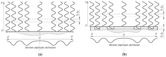
Figure 2.
Diagrams of generation of ultrasonic radiation using bending and oscillating ultrasonic disk radiators: (a) radiator with a flat frontal surface (flat radiator); (b) radiator with phase-aligning collars (step-function radiator).
As follow from Figure 2a, the neighboring annular domains of the disk generate equal-amplitude oscillations in antiphase. Such a radiator enables the generation of an inhomogeneous ultrasonic field, in which vortex flows between the regions oscillating in counter-phase can be formed. In this version of the radiator, the characteristic dimensions of the vortices generated will be determined by the wavelength of ultrasonic vibrations in the gas medium, and their number—by the number of neighboring areas of the ultrasonic field oscillating in counterphase and the distance between the radiator and the reflector [23,29].
To ensure phase synchronism (generation of homogeneous ultrasonic field) of vibrations emitted into the gas medium from each annular domain, the front surface of this type of radiators has a stepwise profile (Figure 2b). The arrangement and size of the projections on the front surface determine the key parameters of the ultrasonic field generated by the radiator. Therefore, to generate a uniform ultrasonic field, step-type transitions are made in the node circle zones with a height equal to half of the wavelength of ultrasonic vibrations in the gas medium. Thus, generation of a uniform ultrasonic field is ensured both when the reflector is installed at a resonant distance from the oscillating surface of the radiator and when it is not available.
It is known that the lower the frequency of exposure, the easier it is to create a high sound pressure level. Therefore, when conducting experimental studies, the frequency of exposure was chosen at the level of the upper limit of audibility of the human ear ≥ 22 kHz (at this frequency, exposure with the sound pressure levels indicated in this article is safe).
Figure 3 shows the vibration distributions and pictures of the fabricated radiators of both types.
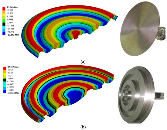
Figure 3.
Modal shape distribution of vibrations and photo of ultrasonic disk radiators: (a) flat radiator; (b) step-function radiator.
Each piezoelectric transducer connected to the radiator is equipped with an electronic generator for its power supply, which maintains constant amplitude of oscillations. Ultrasonic disk radiators are made of Grade2 titanium.
The plate radiators (flexural–oscillating disks) used in the work are specially designed so that at the required oscillation frequency, excitation is carried out only on one circular (concentric) flexural mode of oscillation. For this purpose, the disk profile is made of a step-variable section. The front side of the disk determines the direction of radiation, and the back side provides the required distribution of vibration amplitudes.
Analysis of the operation of the radiator and adjustment of the dimensions of the radiator are performed based on the simulation results (using modal analysis).
It is known that the excitation of complex uncontrolled vibration modes leads to an increase in mechanical stress and damage to the radiator. To ensure stable operation of the radiator and eliminate changes in the oscillation shape, the frequencies of the nearest oscillation modes are separated from the frequency of the main oscillation mode by at least 200 Hz.
When assembling and setting up a disk radiator, the ring mode of oscillation is determined visually using indicator powder [35].
- (1)
- To do this, the radiator is excited using a generator (supply voltage 20 volts).
- (2)
- Indicator powder is applied to the surface of the radiator (must be installed horizontally).
- (3)
- The generator frequency is changed in the range F (calculated) ±10%. When resonance is established on the desired vibration mode, the indicator powder moves to the zeros of vibration due to vibrations.
- (4)
- Next, the resulting distribution of vibration zeros is compared with the distribution of zeros obtained using modal analysis in the ANSYS system.
The technical specifications of the ultrasonic transducers are presented in Table 1.

Table 1.
Specifications of ultrasonic transducers.
3. Results
3.1. Calculation of Sound Pressure Distribution in Coagulation Chamber
The ultrasonic field parameters were estimated in order to establish conditions of the most effective impact and comparative analysis of sound pressure level distributions generated by means of different radiators, provided the distance from the radiator to the reflector (for both flat surface and step-function type radiators) at which the occurrence of the standing wave is ensured.
Modeling of vibration distribution was carried out by means of finite element analysis using ‘Harmonic Acoustics’ harmonic acoustic analysis module. During modeling, the boundary conditions were set on the basis of obtained experimental data regarding parameters of developed and manufactured ultrasonic radiators (frequency of vibrations and vibration amplitudes distribution of the radiating surface). The surfaces of the internal walls of the chamber are specified as reflecting boundaries with a certain absorption level. By comparing the results of modeling with the values of sound pressure level measured experimentally, the level of absorption of ultrasonic vibrations by the walls of agglomeration chamber was determined, which amounted to 11%. This value is accepted in further calculations.
3.2. Analysis of Sound Pressure Distribution
The sound pressure level distributions for both radiators are shown in Figure 4. It follows from presented results that there is a sound pressure level between the radiator and the reflector (160–172 dB) sufficient for particle agglomeration. The distance (wavelength λG = 15 mm) at which the maximum sound pressure level is reached is also determined.
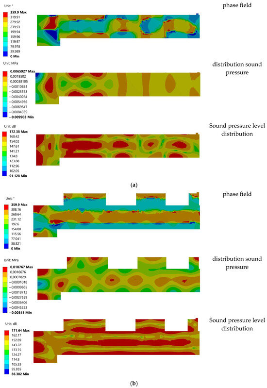
Figure 4.
Sound pressure level distribution phase field and distribution sound pressure inside the agglomeration chamber: (a) flat radiator; (b) step-function radiator.
It established that the sound pressure level between the reflector and the radiator when using the step function radiator is 168–171 dB, a uniform ultrasonic field is generated therein, and when a flat radiator is used it is 168–172 dB, the generated field is inhomogeneous, the areas of the minimum sound pressure level, which are located near the zeros of vibrations of the disk radiator, are clearly pronounced.
As follows from the presented results, for a step radiator, the sound pressure amplitude gradient has a non-zero component only along the acoustic axis. This means that the equivalent force that can initiate the “sonic wind” is also directed along the acoustic axis. However, since the reflector located opposite the radiator serves as an obstacle to the “sound wind”, no acoustic flows are actually formed in the air gap with a step radiator. In this case, the equivalent force leads to the formation of a static pressure gradient in the gas, counteracting the force (a single vortex flow may occur due to the inhomogeneity of the field along the perimeter of the radiator).
It follows that the step radiator is not capable of creating conditions that further increase the efficiency of particle agglomeration. Choosing a certain distance between the radiator and the reflector can lead to an increase in the sound pressure level due to the phenomenon of resonance. However, even with a resonant layer thickness (15 mm), the created sound field will not ensure effective agglomeration of particles due to their short residence time in the gas gap.
For a flat radiator, the sound pressure amplitude gradient (and since there is absorption of vibrations, there will also be a phase gradient) has non-zero components along all coordinate axes. In this case, depending on the position of the observed point in space, the amplitude gradient can be directed at different angles (from 0 to 2π) to the surface of the radiator. This means that the equivalent volume force capable of initiating the “sonic wind” has similar directions, creating a vortex motion. In this case, the surface of the radiator and reflectors do not interfere with the movement of the gas flow and, therefore, the occurrence of acoustic flows with a flat radiator is possible.
According to the presented distributions, there is an amplitude gradient and a phase gradient. In turn, due to the presence of gradients, an equivalent volume force arises acting on the gas phase. The amplitude gradient determines the potential component of the force. And the phase gradient determines the vortex component of the force. In turn, the vortex component is proportional to the vector product of the phase gradient and the amplitude gradient. Since the sound volume is limited, the potential component causes a constant change in pressure. And the vortex component is the emergence of speed. In this case, the center of the vortex emergence will be located in the zones where the vector product of the phase gradient and the amplitude gradient is maximum (including the angle between the phase change and the amplitude change is maximum).
3.3. Particle Path Analysis
At the first stage, the paths of particles in the agglomeration chamber were analyzed using the developed test bench. Particle paths were tracked on the basis of frame-by-frame tracking of tracer particles filmed with a camera. The output power of the generator was set so that the sound pressure level for both types of disks used was at least 165 dB. The resulting frame images are shown in Figure 5.
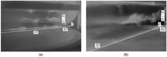
Figure 5.
Particle distribution in the agglomeration chamber: (a) flat radiator; (b) step-function radiator.
Based on the analysis of the obtained particle path data, diagrams of paths travelled by particles in the agglomeration chamber using both types of radiators were plotted (Figure 6 and Figure 7).
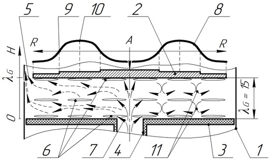
Figure 6.
Diagram of particle paths in the agglomeration chamber when using a flat radiator: 1—chamber body; 2—radiator; 3—reflector; 4—inlet tube; 5—annular domain for emission of the sounded gas-disperse flow; 6—areas of agglomerates formation; 7—gas-dispersion flow; 8—distribution of amplitudes of vibrations of the disk radiator; 9—zeros of vibrations of the radiator; 10—areas of maximum vibration amplitudes; 11—vortex areas.
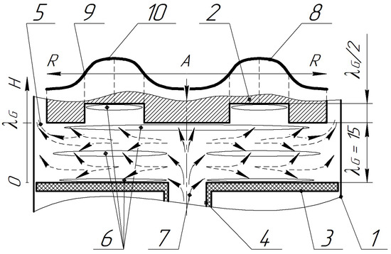
Figure 7.
Diagram of particle paths in the agglomeration chamber when using a step-function radiator: 1—chamber body; 2—radiator; 3—reflector; 4—inlet tube; 5—annular domain for emission of the sounded gas-disperse flow; 6—areas of agglomerates formation; 7—gas-dispersion flow; 8—distribution of amplitudes of vibrations of the disk radiator; 9—zeros of vibrations of the radiator; 10—areas of maximum vibration amplitudes.
When using a flat radiator (at distances of 7.5 and 15 mm), a standing wave is generated with two and three nodal planes of particle velocity, respectively, into which solid particles move, agglomerate and where they are contained. Herewith, intense vortex flows generated due to adjacent regions of the ultrasonic field oscillating in counter-phase originate. As a result, the particles are captured by the vortex motion both within one node areas and between them through the low sound pressure level zones located in the vicinity of (opposite to) the zeros of oscillations of the disk radiator. In this case, in addition to the agglomeration of particles in the node areas of vibrational velocity their additional reciprocal vortex movement and interaction with each other take place, which further results in an increase in the efficiency of agglomeration
Changing the distance to a greater or lesser extent, relative to the resonance distance, results in origination of a traveling wave and disappearance of node areas. At the same time, vortex flows are practically not generated, reducing the efficiency of agglomeration. It is also established that at a distance equal to λ, the intensity of vortex flows is higher than at a distance equal to λG/2. At the distances equal to ¼ λG and ¾ λG, conditions at which the sound pressure level reaches its minimum value become effective.
For comparison, Figure 7 shows a flow diagram for a radiator generating a uniform ultrasonic field.
As in the previous case, when a step-function radiator is used, a standing wave with two and three nodal planes of vibrational velocity into which the solid particles travel, agglomerate and are retained, respectively, is generated when the distance between the radiator and the reflector is 7.5 mm, as well as when the distance is 15 mm.
Further particle agglomeration does not occur due to containment of already formed particles in the standing wave nodes. At the same time, there is no mutual movement of particles within the nodal zone without any additional forced gas flow. Continuous supply of aerosol results in additional increase in the size of particles retained by the ultrasonic field in the node areas. At the same time, the vortex flows are not observed.
3.4. Estimation of Particle Capture Efficiency Based on Gas-Dispersion Flow and Ultrasonic Impact Parameters
To identify the possibility of increasing the capture efficiency using the developed stand, experimental studies were carried out. Research has made it possible to determine the influence of various factors (flow rate of gas-dispersed flow, sound pressure level, mass concentration) on the efficiency of agglomeration of dispersed particles. The efficiency of agglomeration was assessed by comparing the sizes of the initial particles entering the inlet of the agglomeration chamber with the sizes of particles entering the inlet of the cyclone (sampling was carried out in the pipe that connects the cyclone and the agglomeration chamber).
To assess the contribution of ultrasonic agglomeration to the efficiency of the process of collecting dispersed particles, during research, the efficiency of collecting particles entering the inlet of the agglomeration chamber was determined.
The capture efficiency was calculated using the following equation η:
where Noutlet is a particle concentration at the cyclone outlet, g/m3, Ninlet is a particle concentration at the agglomeration chamber inlet, g/m3.
In order to determine the contribution of effects arising from ultrasonic exposure to the process of particle agglomeration, a control experiment was conducted without ultrasonic exposure. In all experiments, the hydrodynamic parameters of the gas-dispersed flow and the characteristics of the particles were the same. This made it possible to exclude the influence of factors related to the properties of particles (adhesion, extrusion, etc.) and flow parameters (hydrodynamic turbolization, etc.).
To exclude the influence of other effects arising in the sound field on the agglomeration efficiency (for example, the appearance of higher and lower harmonics, distortion of the waveform at high sound pressure levels), the parameters of ultrasonic exposure for both types of radiators within the same experiment were the same.
3.5. Determining the Optimum Gas Flow Rate
At the next stage, the gas-dispersion flow rate, at which the maximum efficiency of particle capture is ensured, both with and without acoustic impact was determined.
The studies were conducted under the following conditions: the sound pressure level was 165 dB; and initial mass concentration Ninlet = 2 × 10⁻² g/m3. The gas flow rate varied from 2.5 to 10 m3/h. Microtalc Jetfine T1 CA with particle diameter d50 = 1 μm, d95 = 3 μm was used as a dispersed material in the research.
The bulk density of microtalc is 0.9 g/cm3; the true density is 2.8 g/cm3. The studies were carried out at an air temperature of 22 degrees (the temperature was measured at the chamber exit and did not change during the experiments; the radiators were thermostatted) and a relative humidity of 35%.
During the research, it was established that the protrusions and depressions of the stepped disk radiator create disturbances in the gas-dispersed flow, therefore the influence of the created disturbances on the efficiency of particle collection was determined. Therefore, a control experiment (without ultrasonic influence) was carried out using both types of radiators (the radiators were not excited).
Figure 8 shows the dependence of particle capture efficiency on gas flow rate and the dependence of the particle size at the outlet of the agglomeration chamber on the flow rate.
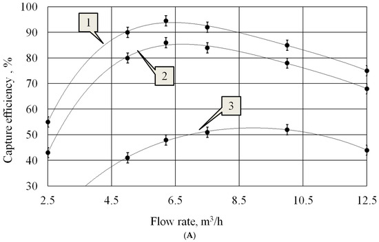
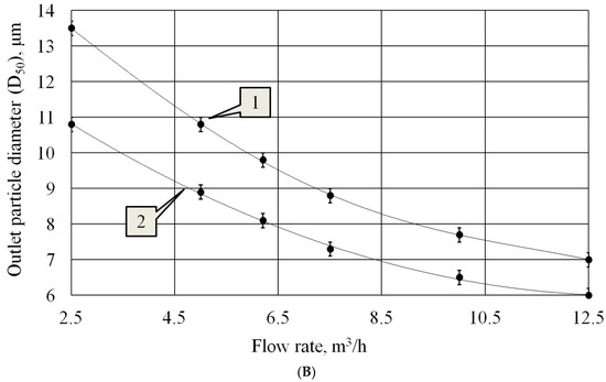
Figure 8.
Dependences of particle capture efficiency on gas flow rate (A) and the dependence of the particle size at the outlet of the agglomeration chamber on the flow rate (B): 1—flat radiator; 2—step radiator; 3—without ultrasonic influence.
The dependence of the efficiency of particle collection on the velocity of the gas-dispersed flow is extreme. The presence of the extremum is due to the mutually opposite dependence of the size of the formed particle agglomerates and the efficiency of particle collection in the cyclone on the air flow speed. As the flow speed increases, the efficiency of the cyclone increases due to an increase in the centrifugal force acting on the particles in the cyclone (Figure 8A). However, at the same time, the size of the aggregates formed in the agglomeration chamber decreases due to a decrease in the residence time of the particles in the ultrasonic field (Figure 8B). This leads to a limitation in the growth of the efficiency of the agglomeration chamber—cyclone system.
It follow form the obtained curves that the best gas flow rate, at which the maximum capture efficiency is provided, is 6.2 m3/h both when using flat and step disk radiator.
However, without ultrasonic impact, the optimum flow rate was 8–10 m3/h, which corresponds to the optimum flow rate for a cyclone.
It has been established that the vortices formed when installing a stepped disk do not affect the agglomeration of particles. The obtained values of capture efficiency are presented in Table 2.
Table 2.
Capture efficiency without ultrasound.
As can be seen from the table, the difference in the collection efficiency values does not exceed the measurement error. Thus, it was found that without ultrasonic exposure, the type of radiator does not affect the collection efficiency. The results obtained made it possible to ignore the influence of the disk stages on the gas flow velocity field. Therefore, for the case without ultrasonic exposure, only one graph is shown, based on average efficiency values for both types of disks.
With a further increase in gas flow (above 6.2 m3/h), in the presence of ultrasonic influence, the capture efficiency begins to decrease. This is due to the fact that reducing the size of the formed agglomerates (due to a further reduction in the residence time of particles in the agglomeration chamber) becomes a determining factor affecting efficiency.
When the flow rate exceeds 8–10 m3/h, the decrease in efficiency increases. This can be explained by the additional influence of the cyclone itself, the effectiveness of which is reduced due to increased turbulization of the flow, which leads to mixing of the flow in the cyclone, reducing stratification
This indicates that the efficiency of particle agglomeration has a greater influence on the capture efficiency than establishing the optimum gas flow rate.
Thus, the efficiency of particle agglomeration under the impact of ultrasonic vibrations depends on the gas flow rate (on duration of ultrasonic exposure). It is obvious that the longer the period of ultrasonic exposure, the higher the efficiency of agglomeration.
In addition, analysis of the relationships presented in Figure 8B showed that there is a nonlinearity in agglomeration efficiency versus flow rate. In the case of using a stepped radiator, nonlinearity is associated with an increase in the probability of collision of large particles held at the nodes of a standing wave with newly arrived particles.
An increase in flow speed leads to the separation of large particles from the nodal areas and their entrainment into the cyclone.
When using a flat radiator, nonlinearity is associated both with the factor described above and with a decrease in the intensification of agglomeration due to acoustic flows. In this case, the movement of particles between nodal regions by acoustic flows is reduced. As a result, with increasing gas flow, the agglomeration efficiency curves for both types of radiators approach each other.
Further studies were conducted with an optimum flow rate of 6.2 m3/h.
3.6. Effect of Sound Pressure Level on Particle Capture Efficiency
To determine the influence of the sound pressure level on the capture efficiency and particle size at the outlet of the agglomeration chamber, dedicated experimental studies were carried out at a concentration of Ninlet = 2 × 10⁻² g/m3. Figure 9 shows the obtained dependencies.
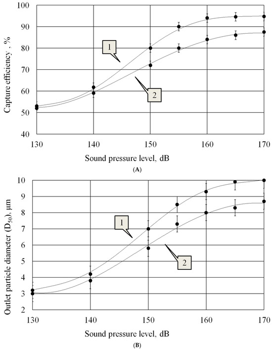
Figure 9.
Dependence of the capture efficiency on the sound pressure level (A) and the dependence of the particle size at the outlet of the agglomeration chamber on the sound pressure level (B): 1—flat radiator; 2—step radiator.
It follows form analysis of the obtained curves that at the initial sound pressure level L = 130 dB the capture efficiency practically does not depend on the used radiator type, there is almost no efficiency gain due to vortex flows, which indicates their insufficient development and influence.
As the sound pressure level increases, an increase in particle capture efficiency is observed. At the same time, the increase in efficiency is more significant when exposed to inhomogeneous field. This is due to the intensification of vortex flows with increasing sound pressure level.
The growth of the capture efficiency continues until the sound pressure level reaches the values of 165 dB, herewith for the step radiator the efficiency is less than 90%. In turn, the vortex acoustic flows generated by the flat radiator at the sound pressure level of 165 dB allow increasing the capture efficiency by 6%.
It is known that when exposed to gas flows or in a non-uniform ultrasonic field, large agglomerates begin to disintegrate due to the influence of acoustic flows [36]. It can be seen from Figure 9B that particle size does not increase significantly above 160 dB SPL. Therefore, we can conclude that no further increase in particle size is observed due to the destruction of agglomerates.
3.7. Effect of Mass Concentration on Particle Capture Efficiency
To determine the influence of particle mass concentration on the capture efficiency and particle size at the outlet of the agglomeration chamber, experimental studies were carried out at a sound pressure level of 165 dB. The curves below (Figure 10) were obtained as a result of these studies.
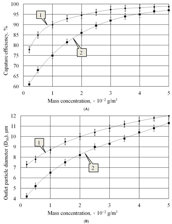
Figure 10.
Dependence of capture efficiency on particle mass concentration (A) and the dependence of the particle size at the outlet of the agglomeration chamber on the mass concentration of particles (B): 1—flat radiator; 2—step radiator.
As follow from the presented curves, at concentrations up to Ninlet = 2 × 10⁻² g/m3 the particle capture efficiency increases significantly. At the same time, the capture efficiency is higher when using a flat radiator, due to increased efficiency of particle agglomeration. At concentrations of Ninlet = 3 × 10⁻² g/m3 and above, the increase in efficiency slows down, and at concentrations above Ninlet = 4 × 10⁻² g/m3 the capture efficiency becomes almost the same with both types of radiators. This happens because at the specified concentrations the distances between particles appear sufficient for realization of orthokinetic and hydrodynamic mechanisms of particle agglomeration, and the influence of vortex flows has little effect on increasing the particle collision probability.
Analysis of the dependencies presented in Figure 10B shows that the impact of a flat radiator on particles leads to a significant increase in particles already at a concentration of Ninlet = 0.2 × 10⁻² g/m3, while particles with a size of 2.5 μm increase to a size of 7.4 μm. At the same time, due to the impact of a stepped radiator on the particles, the agglomerates at the exit from the agglomeration chamber increase to only 4.2 microns. Such a significant difference in the sizes of agglomerates is due to an additional intensifying factor: acoustic flows arising in a non-uniform ultrasonic field generated by a flat radiator. This allows particles to interact not only within the nodal regions, as happens when exposed to a uniform field generated by a stepped radiator, but also to interact with particles moving from one nodal region to another.
As the concentration increases, the difference between the sizes of the formed agglomerates decreases and, at a concentration of Ninlet = 5 × 10⁻² g/m3, it is less than 10%.
3.8. Determination of Fractional Efficiency
To confirm the efficiency of capturing particles of different sizes, experimental studies were carried out using a mixture of microtalc of different grades (Jetfine T1 CA d50 = 1 μm, Luzenac St30 d50 = 6 μm, Luzenac H50 d50 = 9 μm) which had polydisperse composition. Comparative experiments were carried out at initial particle concentration Ninlet = 2 × 10⁻² g/m3, at three different modes of agglomeration chamber operation: exposure with a flat radiator; exposure with a step-function radiator; without ultrasonic exposure. As a result, the fractional efficiency data shown in Figure 11A were obtained. Figure 11B shows the dependence of the particle size at the outlet of the agglomeration chamber on the particle size at the inlet of the coagulation chamber.
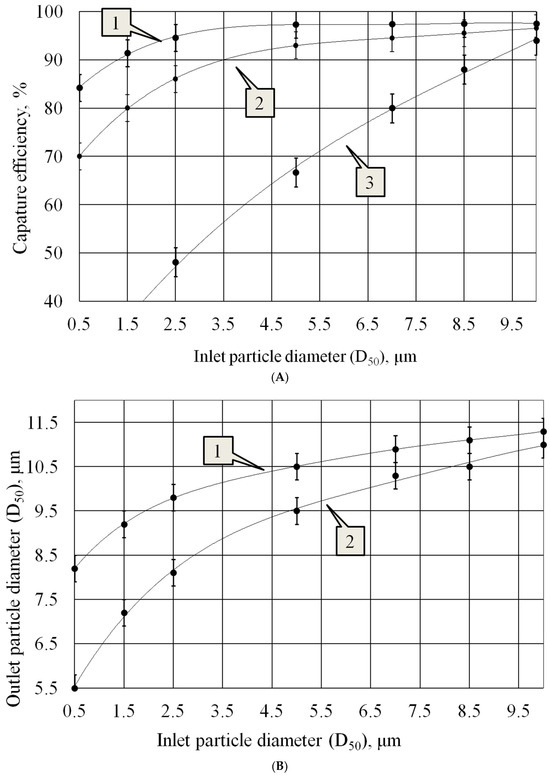
Figure 11.
Fractional efficiency (A) and the dependence of the particle size at the outlet of the agglomeration chamber on the particle size at the inlet of coagulation chamber (B): 1—flat radiator; 2—step radiator; 3—without ultrasonic influence.
The analysis of the obtained curves shows the following:
- Particle capture efficiency without ultrasonic impact (curve 3, Figure 11A) is significantly lower than with exposure to it.
- When using a step-function radiator (curve 2, Figure 11A), when a standing wave is generated, the particles hardly interact with each other within the node areas, and at very low concentration the agglomeration efficiency is reduced to zero.
- The use of a flat radiator (curve 1, Figure 11A) enables generation of vortex flows between adjacent regions oscillating in counter-phase, which significantly increases the interaction of particles located in nodal zones.
- The dependences presented in Figure 11B allow us to conclude that when exposed to a flat radiator, the maximum increase in agglomeration efficiency is achieved on the smallest particles
Thus, the results of experimental studies have confirmed that increasing the efficiency of ultrasonic agglomeration can be reached owing to generation of acoustic streaming in the form of vortex flows. In this case, the efficiency of capturing particles of 2.5 µm in size increases by 6%—from 89% to 95%; particles of 1.5 µm in size by 7%—from 85% to 92%; and particles of 0.5 µm in size by 9%—from 76% to 85%.
3.9. Increasing the Productivity of Gas-Dispersed Flow Processing
The considered design of the agglomeration chamber can significantly increase the efficiency of coagulation, which subsequently increases the efficiency of capturing dispersed particles.
However, the processing capacity of the gas-dispersed flow of such a chamber (with a disk diameter of 320 mm) is no more than 10 m3/h. To increase productivity, the authors proposed the design of an agglomeration chamber with several parallel oscillating plates, which are installed at a resonant distance from each other and implement the identified optimal conditions and modes of ultrasonic exposure. A sketch of the proposed agglomeration chamber is shown in Figure 12.
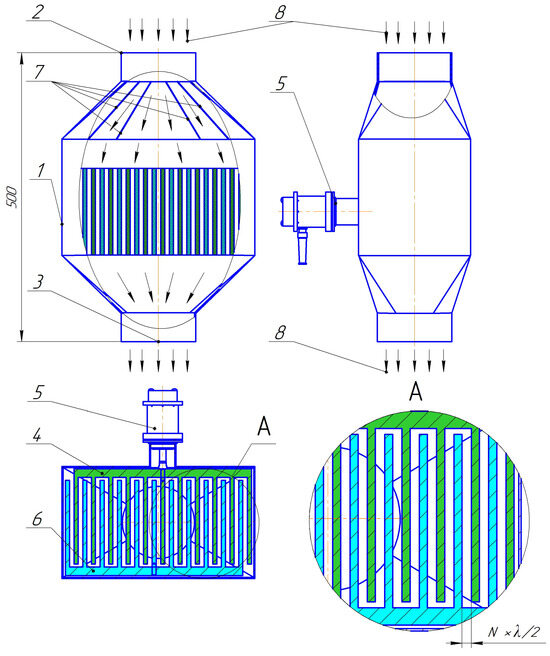
Figure 12.
Design of the ultrasonic agglomeration chamber: 1—housing; 2—inlet pipe; 3—outlet pipe; 4—radiator; 5—ultrasonic piezoelectric transducer; 6—reflector; 7—flow distributors; 8—gas flow; N = 1 … 3; λ—wavelength.
The module is based on an ultrasonic oscillatory system (No. 5, Figure 12) with a plate radiator (No. 4, Figure 12), which are installed in the housing (No. 1, Figure 12). A reflector is installed opposite the radiator (No. 6, Figure 12). The sketch and vibration shape of the plate radiator are shown in Figure 13.
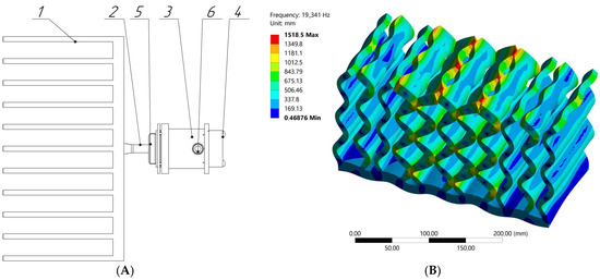
Figure 13.
Ultrasonic oscillatory system: (A) sketch of an ultrasonic oscillatory system; (B) vibration mode of the radiating element; 1—radiating element; 2—piezoelectric transducer; 3—housing; 4—fan; 5—flange; 6—power cable.
The radiator of the oscillatory system is made in the form of parallel plates (No. 1, Figure 13). The plates undergo bending vibrations (Figure 13B). When installing an oscillating system and a reflector in the agglomeration chamber, the distance between the plates of the radiator and reflector is equal to the wavelength of ultrasonic vibrations in the air.
With a resonant distance between the plates of the radiator and reflector in the air gap, conditions are created for the emergence of intense acoustic flows and vortices that promote the coagulation of dispersed particles and the deposition of their aggregates.
In general, the module works as follows. A gas flow containing highly dispersed particles enters the inlet pipe (No. 2, Figure 12). Further, along the direction of gas movement, flow distributors are installed (No. 7, Figure 12), which evenly distribute the gas-dispersed flow throughout the chamber volume.
Next, highly dispersed particles enter the area of ultrasonic influence—the gaps between the plates of the ultrasonic radiator (No. 4, Figure 12) and reflector (No. 6, Figure 12). In this area, high-intensity ultrasonic action occurs on particles and liquid droplets in a thin gas gap.
This design of the agglomeration chamber makes it possible to increase the productivity of processing a gas-dispersed flow in proportion to the area of the radiator.
4. Conclusions
The studies of the agglomeration process of particles of 2.5 µm and less in the ultrasonic field generated by oscillating disk radiators in resonant gaps were carried out in terms of this paper. The conducted studies and presented results of agglomeration of particles of 2.5 µm and less in a uniform field of ultrasonic vibrations confirmed that there is no technical possibility to implement the process with an efficiency of more than 89% for particles smaller than 2.5 µm.
To solve this problem, a new concept of increasing the efficiency of agglomeration through generation of alternating zones in the resonance gaps, in which particles oscillate in counter-phase through the use of bending oscillating ultrasonic disk radiators was proposed.
The studies carried out made it possible to identify the conditions and modes of ultrasonic exposure under which the efficiency of agglomeration increases. It has been established that acoustic streams initiated by a inhomogeneous ultrasonic field make it possible to move particles within the nodal regions of a standing wave and between nodal regions. This increases the efficiency of interaction between particles.
Due to the formation of a inhomogeneous ultrasonic field, the efficiency of particle collection is increased: for PM 2.5, the efficiency reaches 95%; PM 1.5—92%; PM 0.5—85%. The results were obtained under the following conditions: concentration 2 × 10⁻² g/m3, sound pressure level 165 dB, and flow rate 6.2 m3/h. For comparison, when a homogeneous ultrasonic field is formed in the agglomeration chamber (under similar conditions), the efficiency of particle capture by inertial gas cleaning equipment does not exceed: for PM 2.5—89%, PM 1.5—85% and PM 0.5—76%.
To increase productivity, the authors proposed the design of an agglomeration chamber with several parallel oscillating plates, which are installed at a resonant distance from each other and implement the identified optimal conditions and modes of ultrasonic exposure.
Author Contributions
V.N.K.: supervision, conceptualization, reviewing and editing; A.V.S.: methodology, validation, investigation, reviewing and editing; V.A.N.: formal analysis, methodology, software, investigation, validation, reviewing and editing; S.A.T.: investigation, reviewing and editing. All authors have read and agreed to the published version of the manuscript.
Funding
This research was funded by Russian Science Foundation (project No. 19-19-00121).
Institutional Review Board Statement
Not applicable.
Informed Consent Statement
Not applicable.
Data Availability Statement
Data are contained within the article.
Conflicts of Interest
The authors declare no conflicts of interest.
References
- Lu, X.; Zhang, S.; Xing, J.; Wang, Y.; Chen, W.; Ding, D.; Hao, J. Progress of air pollution control in China and its challenges and opportunities in the ecological civilization era. Engineering 2020, 6, 1423–1431. [Google Scholar] [CrossRef]
- Miller, L.; Xu, X. Ambient PM2.5 human health effects—Findings in China and research directions. Atmosphere 2018, 9, 424. [Google Scholar] [CrossRef]
- Pope, C.A.; Ezzati, M.; Cannon, J.B.; Allen, R.T.; Jerrett, M.; Burnett, R.T. Mortality risk and PM 2.5 air pollution in the USA: An analysis of a national prospective cohort. Air Qual. Atmos. Health 2017, 11, 245–252. [Google Scholar] [CrossRef]
- Halonen, J.; Lanki, T.; Yli-Tuomi, T.; Tiittanen, P.; Kulmala, V.; Pekkanen, J. Particulate air pollution acute cardio respiratory hospital admissions and mortality among the elderly. Epidemiology 2009, 20, 143–153. [Google Scholar] [CrossRef]
- Calderón-Garcidueñas, L.; Solt, A.C.; Henríquez-Roldán, C.; Torres-Jardón, R.; Nuse, B.; Herritt, L.; Reed, W. Long-term Air Pollution Exposure Is Associated with Neuroinflammation, an Altered Innate Immune Response, Disruption of the Blood-Brain Barrier, Ultrafine Particulate Deposition, and Accumulation of Amyloid β-42 and α-Synuclein in Children and Young Adults. Toxicol. Pathol. 2008, 36, 289–310. [Google Scholar] [CrossRef]
- Fu, P.B.; Wang, F.; Yang, X.J.; Ma, L.; Cui, X.; Wang, H.L. Inlet particle-sorting cyclone for the enhancement of PM 2.5 separation. Am. J. Environ. Sci. 2017, 51, 1587–1594. [Google Scholar] [CrossRef]
- Hoekstra, A.J. Gas Flow Field and Collection Efficiency of Cyclone Separators. Ph.D. Thesis, Technical University Delft, Delft, The Netherlands, 2000. [Google Scholar]
- Leith, D.; Licht, W. The Collection Efficiency of Cyclone Type Particle Collectors-A New Theoretical Approach. AIChE Symp. 1972, 68, 196–206. [Google Scholar]
- Qian, F.; Wu, Y. Effects of the inlet section angle on the separation performance of a cyclone. Chem. Eng. Res. Des. 2009, 87, 1567–1572. [Google Scholar] [CrossRef]
- Riera, E.; González-Gomez, I.; Rodriguez, G.; Gallego-Juarez, J.A. Ultrasonic agglomeration and preconditioning of aerosol particles for environmental and other applications. In Power Ultrasonics; Elsevier: Amsterdam, The Netherlands, 2015; pp. 1023–1058. [Google Scholar] [CrossRef]
- Ng, B.F.; Xiong, J.W.; Wan, M.P. Application of acoustic agglomeration to enhance air filtration efficiency in airconditioning and mechanical ventilation (ACMV) systems. PLoS ONE 2017, 12, e0178851. [Google Scholar] [CrossRef]
- Chen, H.; Liu, W.; Li, J.; Xun, X.; Shen, X. Experimental Study on Acoustic Agglomeration of Fine Particles from Coal Combustion. In Proceedings of the 2010 International Conference on Digital Manufacturing and Automation, ICDMA, Changcha, China, 18–20 December 2010; Volume 1, pp. 702–705. [Google Scholar] [CrossRef]
- Fan, F.; Zhang, S.; Wang, W.; Yan, J.; Su, M. Numerical investigation of PM2.5 size enlargement by heterogeneous condensation for particulate abatement. Process Saf. Environ. Prot. 2019, 125, 197–206. [Google Scholar] [CrossRef]
- Gallego-Juarez, J.A.; Rodriguez, G.; Acosta, V.; Riera, E. Power ultrasonic transducer with extensive radiator for industrial processing. Ultrason. Sonochem. 2010, 17, 954–964. [Google Scholar] [CrossRef]
- Andres, R.R.; Acosta, V.M.; Lucas, M.; Riera, E. Modal analysis and nonlinear characterization of an airborne power ultrasonic transducer with rectangular plate radiator. Ultrasonic 2018, 82, 345–356. [Google Scholar] [CrossRef]
- Sheng, C.; Shen, X. Simulation of acoustic agglomeration processes of poly-disperse solid particles. Aerosol Sci. Technol. 2007, 41, 1–13. [Google Scholar] [CrossRef]
- König, W. Hydrodynamisch-akustische Untersuchungen. Über die Kräfte zwischen zwei Kugeln in einer schwingenden Flüssigkeit und über die Entstehung der Kundtschen Staubfiguren. Ann. Phys. Chem. 1891, 42, 549. [Google Scholar] [CrossRef]
- Brandt, O.; Freund, H.; Hiedemann, E. Zur Theorie der akustischen Koagulation. Kolloid-Z 1936, 77, 103–115. [Google Scholar] [CrossRef]
- Khmelev, V.N.; Shalunov, A.V.; Nesterov, V.A. Improving the separation efficient of particles smaller than 2.5 micrometer by combining ultrasonic agglomeration and swirling flow techniques. PLoS ONE 2020, 15, e0239593. [Google Scholar] [CrossRef]
- Gallego-Juarez, J.A.; Riera-Franco De Sarabia, E.; Rodriguez-Corral, G.; Hoffmann, T.L.; Gálvez-Moraleda, J.C.; RodrÍguez-Maroto, J.J.; Acha, M. Application of Acoustic Agglomeration to Reduce Fine Particle Emissions from Coal Combustion Plants. Environ. Sci. Technol. 1999, 33, 3843–3849. [Google Scholar] [CrossRef]
- Uchiyama, S.; Asami, T.; Miura, H. Development of an aerial ultrasonic sound source with a truncated cone-shaped reflective plate on a circular transverse vibrating plate. Acoust. Sci. Technol. 2022, 43, 43–49. [Google Scholar] [CrossRef]
- Motoi, R.; Asami, T.; Miura, H. Agglomeration of aerosol using intense standing wave field of cylindrical shape. In Proceedings of the 23rd International Congress on Acoustics: Integrating 4th EAA Euroregio 2019, Aachen, Germany, 9–13 September 2019. [Google Scholar] [CrossRef]
- Khmelev, V.N.; Shalunov, A.V.; Nesterov, V.A. Improving the performance of air purification efficiency from fine-dispersed particles by ultrasonic exposure in swirling flow. Int. J. Environ. Sci. Technol. 2020, 17, 3927–3934. [Google Scholar] [CrossRef]
- Nyborg, W.L. Acoustic Streaming. Phys. Acoust. 1965, 2 Pt B, 265–331. [Google Scholar]
- Lighthill, S.J. Acoustic Streaming. J. Sound Vib. 1978, 61, 391–418. [Google Scholar] [CrossRef]
- Hamilton, M.F.; AIlinskii, Y.; Zabolotskaya, E.A. Acoustic Streaming Generated by Standing Waves in Two-Dimensional Channels of Arbitrary Width. J. Acoust. Soc. Am. 2003, 113, 153–160. [Google Scholar] [CrossRef]
- Aktas, M.K.; Farouk, B. Numerical Simulation of Acoustic Streaming Generated by Finite-Amplitude Resonant Oscillations in an Enclosure. J. Acoust. Soc. Am. 2004, 116, 2822–2831. [Google Scholar] [CrossRef]
- Yong, S.; Sangmo, K. Acoustic Streaming. In Encyclopedia of Microfluidics and Nanofluidics; Springer: New York, NY, USA, 2014; pp. 25–33. [Google Scholar] [CrossRef]
- Bochenkov, A.S.; Golykh, R.N.; Nesterov, V.A.; Tertishnikov, P.P.; Khmelev, V.N.; Tsyganok, S.N.; Shalunov, A.V. Method of Ultrasonic Coagulation. Patent RF2759506, B01D 51/08, 15 November 2021. [Google Scholar]
- Yuen, W.T.; Fu, S.C.; Kwan Joseph, K.C.; Chao Christopher, Y.H. The use of nonlinear acoustics as an energy-efficient technique for aerosol removal. Aerosol Sci. Technol. 2014, 48, 907–915. [Google Scholar] [CrossRef]
- Lü, B.; Darmon, M.; Potel, C. Stochastic simulation of the high-frequency wave propagation in a random medium. J. Appl. Phys. 2012, 112, 054902. [Google Scholar] [CrossRef]
- Kumar, B.P.; Branner, G.R. Generalized analytical technique for the synthesis of unequally spaced arrays with linear, pla-nar, cylindrical or spherical geometry. IEEE Trans. Antennas Propag. 2005, 53, 621–634. [Google Scholar] [CrossRef]
- Tang, Y.; Li, Z.; Cui, Y.; Yang, C.; Lv, J.; Jiao, Y. Micro Non-Uniform Linear Array (MNULA) for Ultrasound Plane Wave Imaging. Sensors 2021, 21, 640. [Google Scholar] [CrossRef]
- Khmelev, V.N.; Shalunov, A.V.; Nesterov, V.A. Summation of high-frequency Langevin transducers vibrations for increasing of ultrasonic radiator power. Ultrasonics 2021, 114, 106413. [Google Scholar] [CrossRef]
- Khmelev, V.N.; Nesterov, V.A.; Shalunov, A.V. Increasing the uniformity of distribution of the oscillations of the disc ultrasound radiators for gas media. IOP Conf. Ser. Mater. Sci. Eng. 2020, 862, 062079. [Google Scholar] [CrossRef]
- Baillot, F.; Blaisot, J.; Boisdron, G.; Dumouchel, C. Behaviour of an air-assisted jet submitted to a transverse high-frequency acoustic field. J. Fluid Mech. 2009, 640, 305–342. [Google Scholar] [CrossRef]
Disclaimer/Publisher’s Note: The statements, opinions and data contained in all publications are solely those of the individual author(s) and contributor(s) and not of MDPI and/or the editor(s). MDPI and/or the editor(s) disclaim responsibility for any injury to people or property resulting from any ideas, methods, instructions or products referred to in the content. |
© 2024 by the authors. Licensee MDPI, Basel, Switzerland. This article is an open access article distributed under the terms and conditions of the Creative Commons Attribution (CC BY) license (https://creativecommons.org/licenses/by/4.0/).