1. Introduction
Composites with a light alloy metal matrix have remarkable strength, low density, and good corrosion resistance [
1,
2]. Due to the unique combinations of these properties, metal matrix composites (MMCs) are increasingly being used for various applications in the automotive and defense industries. Due to their high specific strength and stiffness, boron–aluminum composites are used in the most critical structural elements of aerospace equipment. In many applications, the operating conditions allow the appearance of plastic deformations. In addition, studies of the plasticity of composites are necessary for calculations of limit states of structural elements. This is the reason for the considerable interest in the development of theories of plastic deformation of composite materials.
A large number of publications devoted to the problems of the application of MMCs with an aluminum matrix in the aviation industry are reviewed [
3].
Metal matrix particulate composites are typically characterized by a metal matrix embedded with a distribution of particles, such as graphite, ceramic whiskers, intermetallics, or second-phase particles. These particles generally range in size from 10 µm to 200 µm and are spaced at similar intervals [
4].
Understanding the deformation plasticity behavior of MMCs is essential for optimizing their design and manufacturing processes to meet specific application requirements. The transfer of stress from the matrix to the fiber is recognized as the primary mechanism that influences the deformation and fracture behavior of these MMCs [
5].
The fracture strengths of various MMCs, prepared through different manufacturing techniques such as liquid metallurgy, powder metallurgy, and precipitation, have been extensively analyzed [
4]. These studies have revealed distinct trends in the strength versus volume fraction relationship, shedding light on the underlying fracture mechanisms and microstructural influences. Furthermore, investigations into the initial yield and collapse behavior of fiber-reinforced MMCs have provided valuable insights into the complex interplay between matrix plasticity, the fiber–matrix interface, and residual stresses [
6]. The findings from this study indicate that the loads required to induce failure in MMCs are significantly higher than those needed to initiate initial yielding, especially when accounting for residual stresses generated during manufacturing. Markopoulos et al. [
7] presented a framework for creating 3D statistically similar representative volume elements (SSRVEs) to assess the mechanical properties of AA7075 alloy composites reinforced with carbon fibers at various volume fractions. A numerical analysis showed that the elastic modulus increased with the fiber content, consistent with the rule of mixtures. However, significant differences were found between the simulated yield stresses and those predicted using the shear-lag model. Another study [
8] used the Discrete Element Model (DEM) to simulate fracture toughness tests on a dual material with a structured metal matrix composite (MMC) inside martensitic steel. Various MMC micro-lattices (gyroid, octet-truss, and FBCCZ) were analyzed for their energy absorption and crack resistance. Experimental tests validated the DEM, showing less than 10% error in stress intensity factors. The FBCCZ structure was found to absorb the most energy during crack propagation.
Thermal cycling effects on the mechanical properties of MMCs have also been studied, highlighting the role of material ratcheting in determining the inelastic deformation under cyclic loading conditions [
9]. Additionally, numerical simulations and experimental observations have elucidated the effects of reinforcement orientation on the tensile response of particle and whisker-reinforced MMCs, emphasizing the importance of microstructural alignment and bonding characteristics [
10]. Their findings emphasize the significant decrease in tensile stress levels with small deviations in whisker alignment, highlighting the importance of alignment control for optimizing mechanical properties.
Investigations into the stress–strain behavior in the initial yield stage of short-fiber-reinforced MMCs have led to the proposal of analytical expressions and novel methods for defining yield behavior, revealing the influence of material parameters (fiber volume fraction, fiber aspect ratio, fiber end distance, and matrix strain hardening coefficient) on deformation behavior [
11]. Moreover, studies on the inelastic deformation mechanisms of MMCs have provided insights into the contributions of plasticity and damage mechanisms to the overall deformation response [
12].
Phenomenological constitutive models incorporating damage mechanics and micromechanical behavior have been developed to describe the overall damage and elastoplastic deformation in fibrous MMCs with ductile matrices, offering valuable insights into the material behavior under various loading conditions [
13]. Furthermore, numerical simulations investigating the effects of fiber distribution and cross-sectional geometry on the deformation of MMCs have highlighted the influence of these geometrical variables on the constitutive response and deformation mechanisms [
14].
The mechanical characterization and modeling of non-linear deformation and fracture in fiber-reinforced MMCs have been investigated extensively, with experimental and computational analyses providing valuable insights into the anisotropic mechanical behavior and the development of constitutive models [
15]. The resulting models have demonstrated good agreement between predicted and measured stress–strain responses under various loading conditions, facilitating a deeper understanding of the material’s deformation behavior and failure mechanisms.
Several studies have contributed to the understanding of the mechanical behavior of MMCs under different loading conditions, addressing aspects such as stress transfer, creep behavior, and the impact of microstructural defects and damage evolution.
In the realm of elastic–plastic stress transfer, Khosoussi et al. [
16] developed an analytical approach for the elastic–plastic stress transfer analysis of short-fiber-reinforced MMCs under tensile loading. Their micromechanical model, considering an axisymmetric unit cell, successfully predicted plastic strain terms and stress transfer behavior, and it was validated by a finite element (FE) analysis. Studies on load transfer mechanisms in short-fiber-reinforced MMCs have provided valuable insights into the evolution of internal stresses and deformation behavior [
17], where the load transfer and deformation behavior in aluminum matrix composites reinforced with 2D-random alumina short fibers under different loading modes were investigated. Through neutron diffraction measurements and computational simulations, they elucidated the evolution of stress in the metallic matrix and provided insights into the macroscopic stress–strain behavior, enhancing the understanding of load transfer mechanisms in MMCs. Moreover, numerical modeling approaches were developed to simulate damage development, viscoplasticity, and stress–strain behavior in MMCs, incorporating complex material constitutive relationships and microstructural features [
18,
19]. Also, efforts have been made to understand the elastic–plastic stress transfer mechanisms in short-fiber-reinforced MMCs, with modified shear lag models being proposed to account for matrix plastic deformation and thermal residual stresses [
20]. It was shown that the efficiency of stress transfer in the elastic region decreases due to local plastic deformation in the matrix. In the presence of thermal residual stresses, varying degrees of plastic strain in the matrix lead to asymmetric stress–strain responses under tension and compression. Therefore, these results elucidate the role of matrix plasticity in altering stress transfer efficiency and its implications for the overall mechanical response of the composite material.
In terms of creep behavior, the authors of [
21] introduced an analytical model using circular functions to predict the creep behavior of fibrous composites under axial stress. This model provided simpler predictions of creep strain rates compared to existing methods and was validated against FEM results, showing uniform behavior and potential creep rupture at fiber ends. Reddy et al. [
22] further investigated the effect of the reinforcement fiber diameter on the elevated temperature bending creep deformation behavior of Ni nanocomposites using molecular dynamics simulations. They found that thinner fibers display superior creep properties and increased plasticity due to shear band interactions and work softening. In contrast, thicker fibers exhibit work hardening and tend to fracture through quasi-cleavage mechanisms. Xu et al. [
23] highlighted the significance of interface diffusion on the creep behavior of MMCs at high temperatures, proposing a micromechanics theory based on Eshelby’s solution to understand this phenomenon. Barbera et al. [
24] analyzed the creep–fatigue behavior of aluminum alloy-based MMCs, employing a direct simulation technique within the Linear Matching Method (LMM) framework to improve the understanding of failure mechanisms under varying loads and high temperatures.
The impact of microstructural defects and damage evolution has also been a significant area of research. In [
25], the elastic and plastic behaviors of the QE22 magnesium alloy reinforced with Saffil fibers and SiC particles were studied using scanning electron microscopy and the Halpin–Tsai–Kardos model. The findings reveal different fracture mechanisms between the matrix and the composite, emphasizing the role of a microstructural analysis in understanding composite behavior. The fracture of the matrix alloy primarily exhibited an intercrystalline nature, whereas the failure of the hybrid composite was transcrystalline. Han et al. [
26] explored the role of the aspect ratio of SiC reinforcement in Cu composites. They found that SiC whisker-reinforced Cu exhibits significantly higher strength, plasticity, and thermal conductivity compared to SiC particle-reinforced Cu due to better load transfer and crack bridging mechanisms. The authors of [
27] utilized computational homogenization to investigate the impact of pre-existing microstructural voids on the failure response of ceramic fiber-reinforced aluminum composites. Six virtual models of the composite microstructure, each with different volume fractions and spatial distributions of pre-existing voids, were analyzed to determine their failure responses under macroscopic normal and shear strains. The results indicate that for shear loading, small volume fractions of voids have a negligible impact on the failure response. However, these voids significantly reduce the composite’s mechanical strength under uniaxial and equi-biaxial normal strains. Their study highlighted the significant deterioration of composite mechanical strength due to voids under normal strains, demonstrating the importance of considering microstructural defects in material design. The authors of [
28] developed a theoretical model to describe the impact of interphase and load transfer on the mechanical behavior of CNT-reinforced MMCs. They found that the introduction of an interphase significantly enhances the overall strength of the composites, highlighting the roles of the matrix grain size, reinforcement content, and size in determining material properties.
Additional studies have further enriched the understanding of MMCs. Yokozeki et al. [
29] conducted low-velocity impact experiments on SiC-fiber/titanium matrix composites and developed finite element modeling to simulate the damage behavior of TMCs, considering plastic deformation and damages. Khoddam et al. [
30] proposed a design for a spiral fiber-reinforced metal matrix composite, aiming to enhance its mechanical strength with an analytical model to predict torsional behavior and torque–twist requirements during fabrication. Also, in reference [
16], an analytical method is proposed to study the elastic–plastic behavior of short-fiber-reinforced metal matrix composites under tensile loading. Using a micromechanical approach with an axisymmetric unit cell, the elastic solution is derived first. The matrix undergoes plastic deformation while the fiber remains elastic under normal loading. Successive elastic solutions determine the plastic strain in the matrix. The elastic–plastic stress transfer behavior is analyzed and compared with finite element analysis results, demonstrating the method’s capability to predict plastic strain and stress terms in the matrix. Malachowski et al. [
31] developed a numerical procedure for predicting the parameters of a yield criterion for metal matrix composites based on the known mechanical properties of the matrix and fibers. Mishra and Mahesh [
32] proposed a shear-lag and deformation-theory-based model for a metal matrix composite reinforced by continuous unidirectional fibers, accounting for fiber and matrix cracking, matrix plasticity, and fiber–matrix interfacial sliding. Zou et al. [
33] conducted a micromechanical analysis of a SiC/Ti6Al4V composite under complex stress states, highlighting mechanical property degradation under complex conditions. An analytical method is proposed in [
5] to study how short-fiber-reinforced metal matrix composites behave elastically and plastically under tension. Using a micromechanical approach with an axisymmetric unit cell, the study derives governing equations and boundary conditions and calculates an elastic solution using shear lag methods. The model considers plastic deformation in the matrix due to normal loading while the fiber remains elastic. The analysis examines how this plastic deformation affects stress transfer within the composite.
When carrying out a structural analysis of structural elements, the real properties of composite materials are replaced by the properties of equivalent homogeneous materials. The components of metal matrix composites have significantly different mechanical properties. The elastic properties of fibers can be anisotropic, but matrices are predominantly isotropic. The conditions for the onset of plasticity differ both quantitatively and qualitatively. Beyond elasticity, the stress–strain diagrams of the components obey different hardening laws. All of these differences significantly complicate the construction of plastic deformation models for equivalent homogeneous materials. A promising direction in the field of homogenization of composite materials is to perform a micromechanical numerical analysis of representative volumes of a composite based on the results of experimental studies of the properties of its components. This approach is used in this work to create physical relationships for the elastic–plastic deformation of boron–aluminum fiber composites. The advantage of conducting a numerical prediction of the plastic properties of composites is the possibility of analyzing a large number of variants of structure and properties of components. The approach proposed in this paper requires a minimal amount of experimental data and makes it possible to determine the parameters of the yield criterion and the characteristics of deformation diagrams for different types of loading. The cost-effectiveness of this approach makes it possible to use it for the optimal design of metal matrix composites.
2. Government Equation for Equivalent Homogeneous Orthotropic Materials
Modern technologies to produce fibrous metal matrix composites make it possible to create regular structures in which a periodically repeating representative volume element (RVE) can be distinguished. The characteristic dimensions of such software are comparable to the radius of the fibers, which is many orders of magnitude smaller than the dimensions of real structural elements made of composite materials. The concept of homogenization consists of replacing the real structure of the composite with an equivalent homogeneous material, and its state is characterized by the values of the stress and strain tensor components averaged over the volume of RVE [
34]:
Here, represent the components of the Cauchy stress tensor, represent the components of the linear strain tensor inside the RVE, represent the average stresses, and represent the average strain values for an equivalent homogeneous material.
The physical relations of the elastic–plastic deformation of composites are formulated relative to the average characteristics for an equivalent homogeneous material. Before the first plastic strains appear, Hooke’s law is used for an anisotropic body [
35]:
where
Aijkl represent components of the elastic tensor of equivalent homogeneous material.
Yield criterion. When a certain limiting state is reached, the first plastic deformations appear in the composite. For an equivalent orthotropic material, the criterion for the onset of plasticity is formulated in the form of an invariant quadratic form with respect to the average stresses [
31]:
Due to the symmetry of the stress tensor, the components of the fourth-rank tensor must satisfy the conditions
Bijkl =
Bjikl =
Bklij. Independent components
Bijkl determine the elastic limits for various types of complex stress states. The number of such independent components depends on the symmetry type of the equivalent homogeneous material. In particular, for an orthotropic material, criterion (3) contains nine components. For homogeneous orthotropic materials, Hill’s hypothesis of plastic incompressibility is widely used. This makes it possible to exclude the first invariant of the stress tensor from consideration and reduce the number of independent components to six in the yield criterion. However, Hill’s hypothesis is not applicable to composite materials, even if all of their components are incompressible. A theoretical explanation of this effect is given in [
31] based on the results of a micromechanical analysis of an orthogonally reinforced composite.
Plasticity model. To create physical relations of the plastic deformation of metal matrix composites, a quadratic yield function and its associated flow rule are introduced. In the initial unreformed plastic state, the yield function corresponds to the plasticity criterion (3). To reflect the anisotropy of hardening, a kinematic scheme of plasticity surface variation is used. In the proposed version of the plasticity function, it is possible to take into account different hardening rates when stretching in different directions and shearing in different planes. Within the framework of the homogenization concept, the plasticity function is formulated with respect to the tensors of average stresses and plastic strains:
Here,
represent so-called back stresses, which determine the displacement of the plasticity surface as a result of hardening. In contrast to traditional variants of the plasticity theory [
35], the tensor of the fourth rank
is introduced to account for the difference in the rate of hardening during different types of deformation. The components of this tensor are determined by the tangents of angles for the diagrams of stress–plastic strain dependences. For the development of new plastic deformations, two conditions of active loading must be fulfilled [
36]:
Then, the components of the tensor of plastic strain increments are determined by the associated flow law with accuracy up to the multiplier
:
These relations determine the direction of the vector of plastic strain increments perpendicular to the plasticity surface. Under active loading, stress increments cause new plastic deformations, but condition
F = 0 is satisfied, and the total differential of the plasticity function is equal to zero:
This condition, together with Formula (2), makes it possible to determine the scalar multiplier
for known increments of stresses:
Formula (8) sets the norm of the vector of plastic strain increments in explicit dependence on stress increments. If the stresses do not satisfy yield criterion F < 0 or the stress increments satisfy the inequality
, then
= 0. When the active loading conditions (5) are met, the components of the plastic deformation increment tensor are determined by taking into account the accumulated plastic deformations.
The presented plasticity model of an equivalent homogeneous material contains a number of material parameters. These include elastic constants in Hooke’s law (2) and tensor components in the plasticity criterion (3) and plasticity function (4). In addition, the plasticity function contains components of the tensor to account for differences in the rate of hardening under different types of stress states. The classical method of determining material parameters in a material model involves performing physical experiments. Even for homogeneous anisotropic materials, this method requires a large number of experiments and the fabrication of special samples. In the case of composites, the situation is also complicated by the variety of structures and types of reinforcement. A more rational approach for composites is a combined approach in which the physical properties of the components are determined experimentally, and homogenization is performed theoretically. In the present work, such an approach is implemented for an orthogonally reinforced metal matrix composite using a finite element homogenization procedure.
3. Numerical Homogenization in an Orthogonally Reinforced Composite
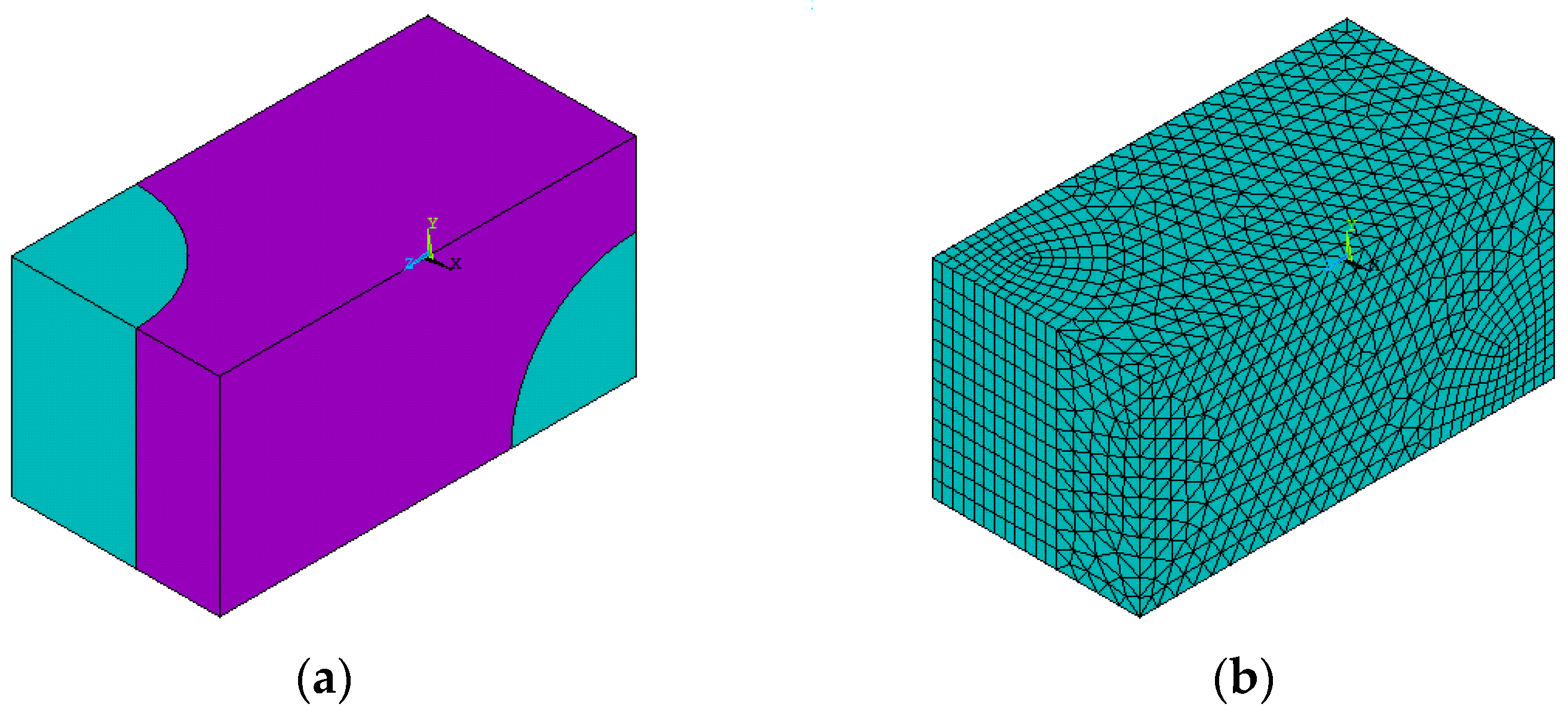
Let us consider a boron–aluminum composite reinforced with continuous fibers in two mutually perpendicular directions. Due to the regularity of the composite structure, it is sufficient to perform a micromechanical analysis of the periodically repeating representative volume element (RVE). The geometrical model of RVE is shown in
Figure 1a. The relative (related to the length of the edge parallel to the x-axis) dimensions of the sides of the parallelepiped are 1 × 1 × 2, and the radius of the fiber is 0.6.
The experimental basis for determining the effective characteristics of an equivalent homogeneous material is the mechanical properties of boron fibers and an aluminum matrix from [
34]. The elastic modulus and Poisson’s ratio of boron are 420 GPa and 0.3, and those for aluminum are 7.1 GPa and 0.34. To approximate the aluminum deformation diagram, a bilinear function was adopted with a yield strength of 262 MPa and a tangential modulus of 8.72 GPa.
All stages of numerical homogenization were performed using a structural analysis of RVEs with the finite element method in the ANSYS 2021 R1 software package. To create a finite element model (
Figure 1b), the higher-order 3D 20-node SOLID186 element was used. The geometrical model of the RVEs consists of two volumes belonging to the fibers and one to the matrix. When creating the finite element model, the corresponding material properties were set in the mesh attributes for these volumes. On the boundaries between the volumes, the conditions of continuity of nodal displacements were fulfilled. In “Mesh Tool”, the smart sizing option was used with “Fine 1”, and the parameters of the “Mesher Options” were set by the program choice option. The number of elements between the components of the structure was distributed as follows: fiber—2592; matrix—16,837 elements. All of the results presented in this work were obtained using a finite element model consisting of 19,429 elements and 36,138 nodes.
The homogenization of the elastic properties of the composite. For the composite structure under consideration, the equivalent homogeneous material is orthotropic. In this case, it is convenient to combine the coordinate planes of the Cartesian coordinate system with the symmetry planes of the composite. Using Voigt notation, the stress–strain relationship is represented in matrix form:
The mechanical properties of the composite in the directions of the OX and OY axes are the same; therefore, the matrix components satisfy the following equalities: = , = , = .
To determine the elastic characteristics of the composite, a special methodology for a numerical simulation of basic experiments was used [
37]. In each numerical experiment, a certain type of homogeneous stress state of an equivalent orthotropic material is modeled. For this purpose, a micromechanical analysis of the RVEs is performed under a specially designed system of boundary conditions on the surfaces of the RVEs (
Table 1). These boundary conditions are used only for the homogenization procedure, the purpose of which is to calculate the effective properties of an equivalent homogeneous material. These boundary conditions ensure that the stress–strain state inside the RVEs fully corresponds to the state that occurs in each RVE during the homogeneous deformation of the unbounded volume of the composite. For example, in a numerical experiment that simulates homogeneous stretching of an equivalent orthotropic material only in the x-axis direction, the boundary conditions are given in the first row of
Table 1. These conditions both specify such a change in the shape of the RVEs that the original rectangular parallelepiped remains rectangular after deformation, but only the edge parallel to the x-axis is elongated.
In each numerical experiment, the boundary conditions set one non-zero average value (10
−3) of the strain tensor. Based on the results of the micromechanical analysis, all of the characteristics of the stress state, including all of the components of the average stress tensor, are determined. Consecutive processing of the results of numerical modeling of basic experiments makes it possible to determine all components of the matrix (10), and after calculating the inverse matrix, the technical elastic constants of the composite can be found (
Table 2). Details of this process are given in
Appendix A.
The numerical prediction of the yield criterion parameters. For the considered orthotropic material in the coordinate system coinciding with the symmetry planes of mechanical properties, criterion (3) contains six independent constants and can be written in the following form:
To determine the parameters of criterion (11), it is necessary to know the yield strength under uniaxial tensile stresses in two directions,
and
, shear in two planes,
and
, and under simultaneous tension in two directions with equal stresses,
and
. Parameters
Cij are related to yield strengths by the following relations:
In the framework of the proposed approach, the determination of yield strengths is performed by a micromechanical analysis of RVEs. To this end, the stress states under the elastic deformation of the composite under uniaxial tensile, shear, and biaxial stretching were numerically modeled. For these basic experiments, average strain values were determined using the technical elastic constants given in
Table 2. The procedure for the formation of boundary conditions for finite element modeling of the basic experiments was developed in [
31]. The average value of the coordinate stress in the RVEs, at which the first plastic deformations appear in the aluminum matrix, is taken as the corresponding yield strength. The results of the performed numerical experiments are summarized in
Table 3, and the parameters of plasticity criterion (11) for the equivalent orthotropic material are given in
Table 4.
Testing using Sylvester’s criterion showed that quadratic form (11) is positive, definite, and defines a closed hyper surface in the six-dimensional space of coordinate stresses. In the three-dimensional space of normal stresses, this quadratic form defines an ellipsoid with the following principal semi axes: 419 MPa, 302 MPa, and 166 MPa. The strict convexity of the surfaces determined by yield criterion (3) and the plasticity function (4) make it possible to unambiguously determine the increments of plastic deformations using the associated flow law (6).
Numerical modeling of hardening processes. The proposed version of the physical relations of plastic deformations (4)–(9) makes it possible to model the anisotropy of translational hardening. Depending on the structure of the tensor , it is possible to take into account differences in stress–plastic strain diagrams under different loading programs. For composites with an orthogonal symmetry type, it is natural to keep the same assumptions about the structure of the tensor as were made for elastic property tensor (10) and plasticity criterion (11). Taking into account the difficulty of identifying the parameters of this tensor from the results of the physical experiments, we should limit ourselves to the diagonal form of its representation using Voigt notation. In such version of the physical relations for the considered composite, tensile diagrams in two directions and shear diagrams in two planes of symmetry of mechanical properties are necessary to identify the parameters of the hardening tensor.
In the framework of the proposed approach, all necessary diagrams are constructed based on the results of a micromechanical analysis of RVEs using the finite element method. To construct each diagram, a series of calculations with increasing values of total strains within the range of 0 to 5% were performed.
The system of boundary conditions for modeling elastic–plastic analysis was formed similarly to that given in
Table 1. For uniaxial stretching along the 0X axis, the displacements were set within 0 < u
x < 5 × 10
−2 on the
x = 1 surface, and for stretching along the 0Z axis, they were set within 0 < u
z < 10
−1 on the z = 2 surface. Shear modeling in the XY plane was performed by specifying displacements within 0 < u
y < 5 × 10
−2 on the
x = 1 surface, and for shear modeling in the XZ plane, displacements were specified within 0 < u
x < 10
−2 on the
z = 2 surface.
4. Results and Discussion
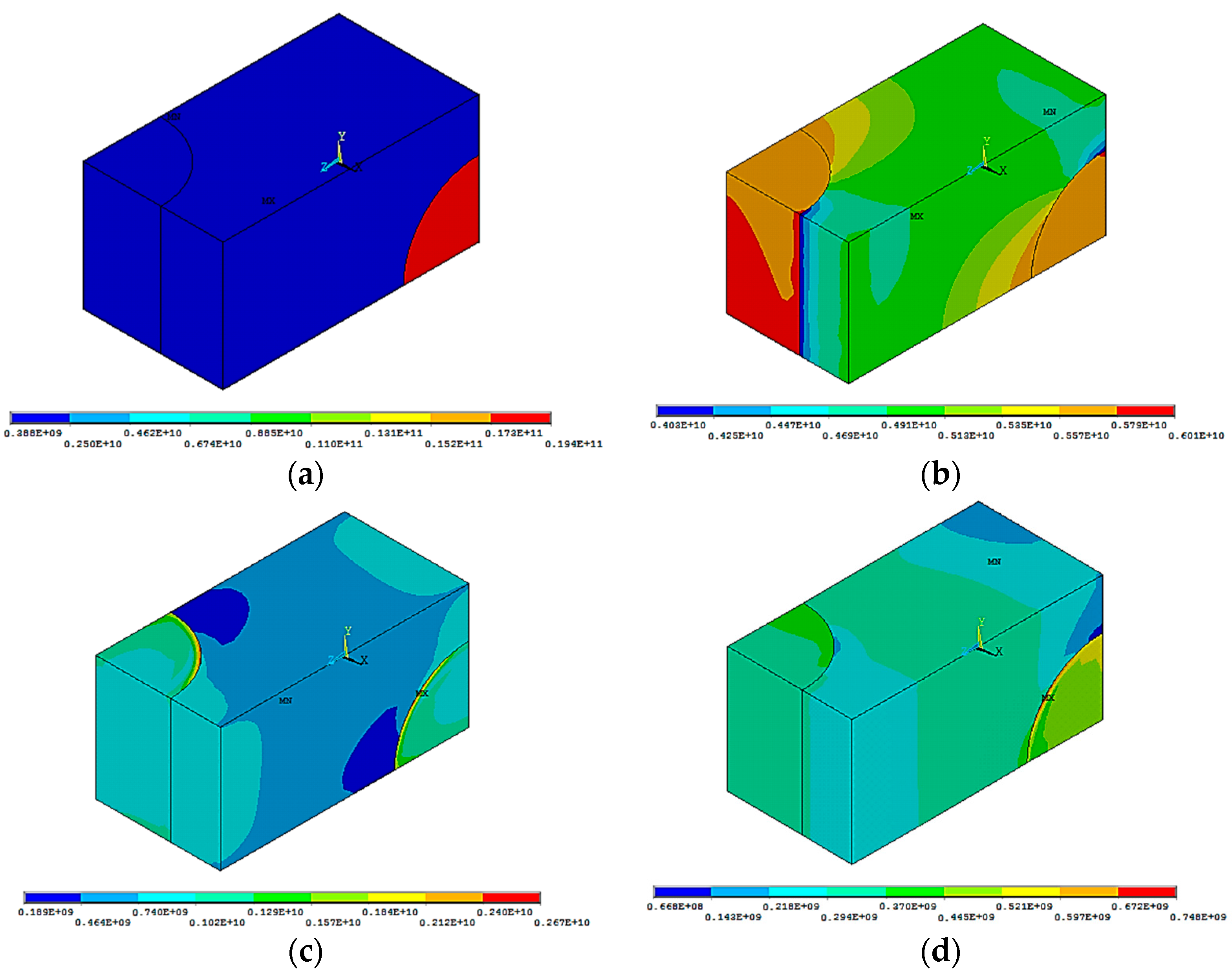
The results of finite element modeling of tension and shear processes are shown in
Figure 2 and
Figure 3. Distributions of equivalent (von Mises) stresses and plastic strains are given for the final steps of the deformation processes.
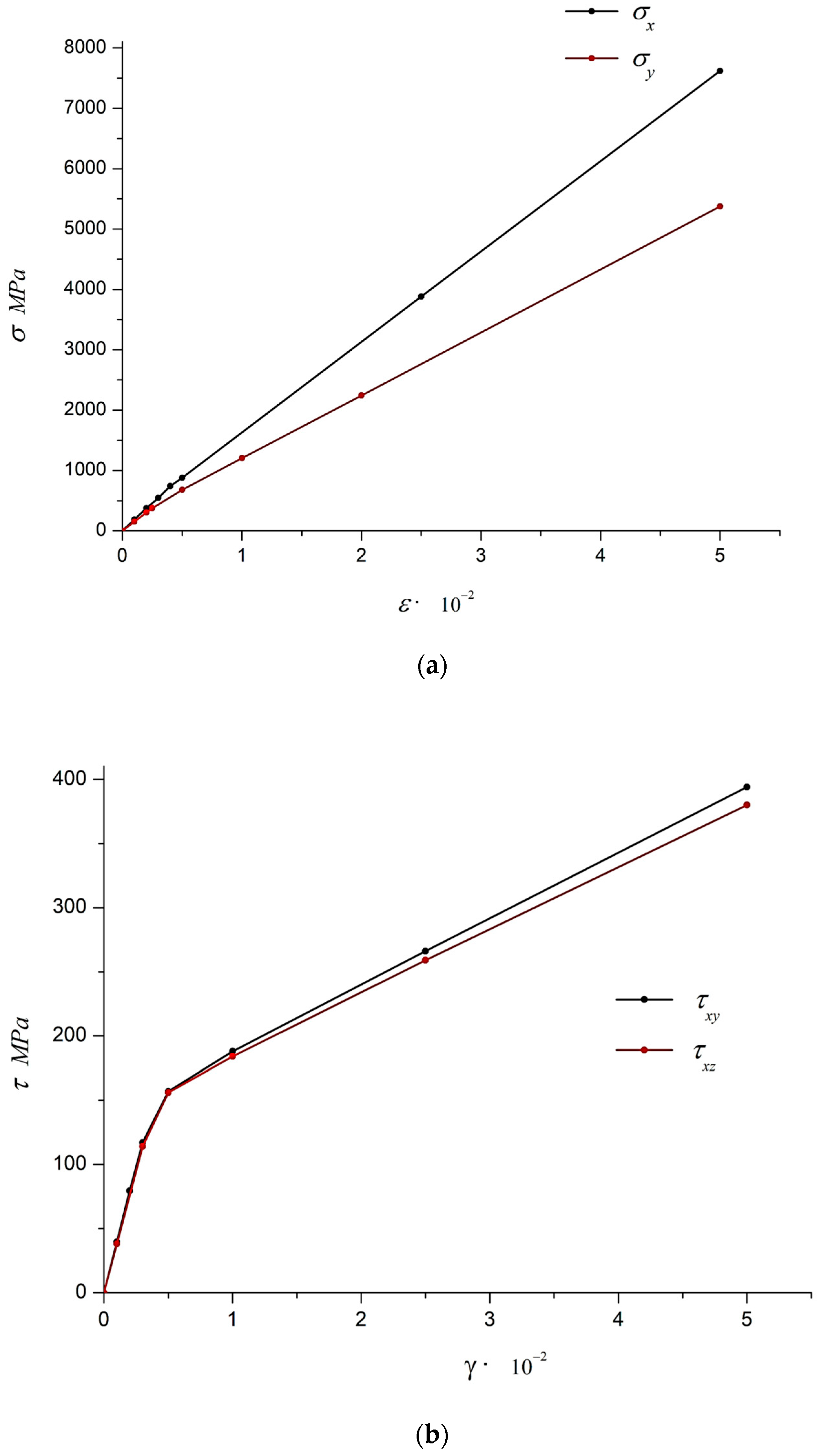
The average values of coordinate stresses in all numerical experiments were determined in the postprocessor of the ANSYS program complex. The processing of results for the numerical solution of elastic–plastic problems is presented in
Figure 4, which shows the calculated strain diagrams for stretching and shear.
The used form of plasticity function (4) in cases of uniaxial tension or pure shear leads to a stress–plastic strain diagram with linear hardening. In particular, for tension along the 0X axis, the hardening section is given by the following equation:
The above is calculated while taking into account that elastic deformation leads to a bilinear deformation diagram, and the approximation of the calculated diagram (
Figure 2a) allows one to determine the parameter
. As a result of processing all calculated deformation diagrams, all components of the hardening tensor were obtained, which are given in
Table 5.
Finite element modeling of plastic deformation processes of an orthogonally reinforced composite predicts significant anisotropy of translational hardening. Plasticity theories since Prager’s work [
36], in which the back stresses
are assumed to be equal to the plastic strains multiplied by a constant or by a scalar strain function, do not reflect this feature of composite materials.
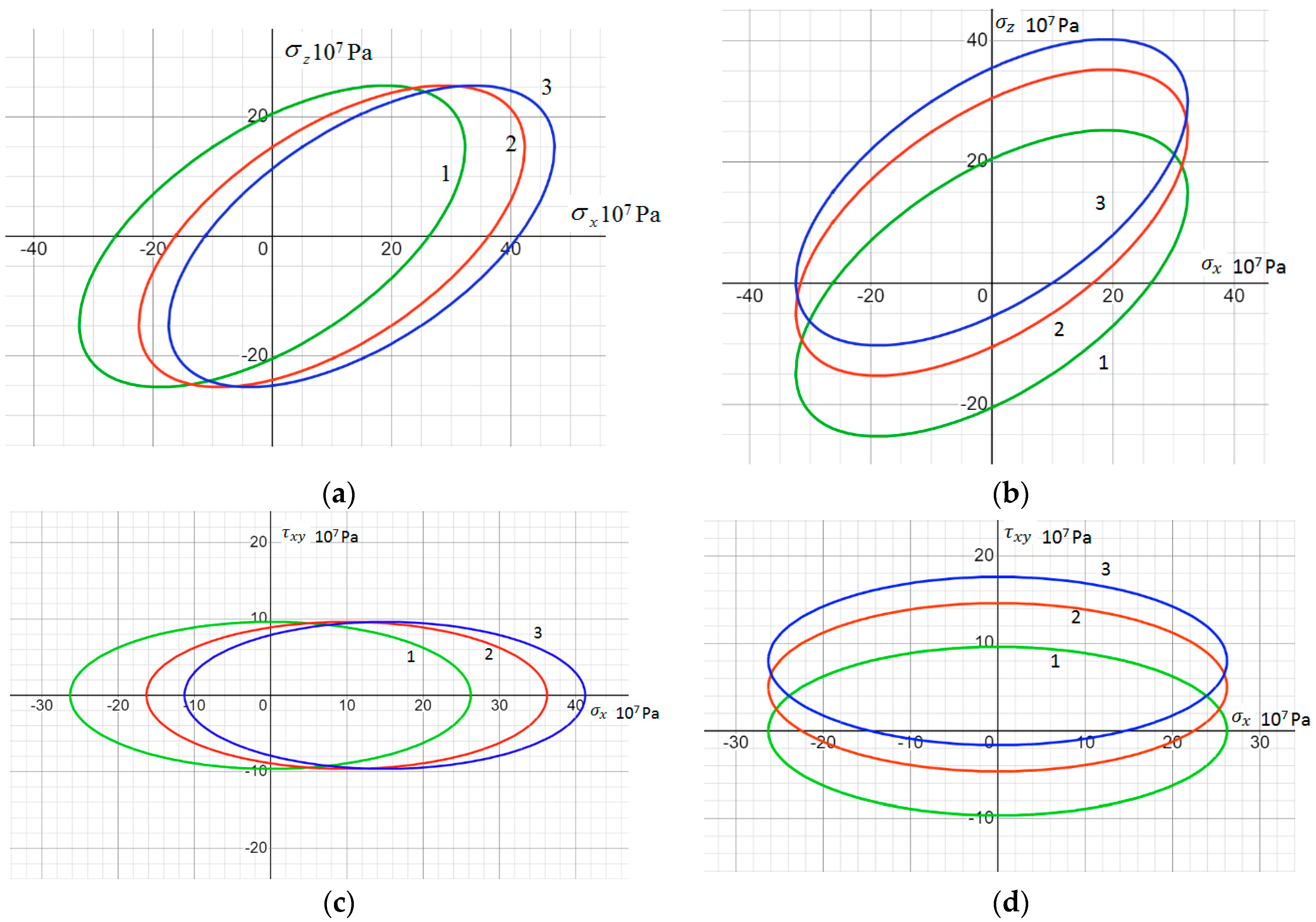
As a visual illustration of the shift in the plasticity surface,
Figure 5 shows its sections by planes corresponding to two non-zero coordinate stresses,
and
, at different values of the back stress,
(0—line 1; 10
7 Pa—line 2; 1.5 × 10
7 Pa—line 3).
The anisotropy of the plastic properties of a boron–aluminum composite is manifested not only in the difference in yield strengths in different directions, but also in the plasticity surface shift rate. As can be seen from the data in
Table 5, the ratio of the increment of back stresses to the increments of plastic deformations differs significantly depending on the type of deformed state.
5. Conclusions
In this paper, a new generalized quadratic yield function is proposed to describe plastic anisotropy in metal matrix composites. The peculiarity of the reflection of kinematic hardening is that the back stresses are specified using a special fourth-rank tensor. The components of this tensor make it possible to take into account the difference in the dependence of back stresses on plastic strains for different tensile directions and different shear planes. The proposed dependence for the back stress tensor satisfies the fundamental invariance requirement and can be used in an arbitrary system of orthogonal coordinates. The initial determination of the components of this tensor is naturally performed in the system related to the symmetry planes of the composite structure.
As an alternative to determining all material parameters of the mathematical model using physical experiments, this paper uses a numerical homogenization procedure. The mechanical characteristics of the matrix and fibers, as well as the geometric structure of the reinforcement, are taken as input data. The micromechanical analysis of RVEs was performed using the finite element method in the ANSYS software package. A series of numerical experiments were performed to predict the elastic properties of the composite, parameters of the yield criterion, and modeling of tensile and shear processes. The components of the additive stress tensor were determined as a result of processing the calculated strain diagrams. This made it possible to calculate all material parameters necessary for a structural analysis in finite element program complexes.
The methodology outlined in this paper is applicable to composites with a proper orthogonal reinforcement structure. In such cases, symmetry conditions can be used for a micromechanical analysis of the representative volume. For other variants of periodic structures, the periodicity boundary conditions should be applied. For stochastic reinforcement with short fibers, the proposed approach is also applicable, but then the representative volume should include a sufficiently large number of fibers. A promising direction for further research is to take into account the non-linear nature of matrix hardening, which is characteristic of new aluminum-based alloys. Possible clarification of the interaction scheme between the components of the composite may be the purpose of future works.
The created methodology allows for a theoretical prediction of the development of plastic deformations in metal matrix composites and for a computer analysis of the limit state of structural elements made of such materials to be carried out. The possibility to carry out multivariate calculations at the design stage provides a significant economic effect when choosing the optimal structure of the composite.


