Abstract
To further improve the braking energy recovery efficiency of battery electric vehicles and increase the range of the cars, this paper proposes a multi-mode switching braking energy recovery control strategy based on fuzzy control. The control strategy is divided into three modes: single-pedal energy recovery, coasting energy recovery, and conventional braking energy recovery. It takes the accelerator pedal and brake pedal opening as the switching conditions. It calculates the front and rear wheel braking ratio allocation coefficients and the motor braking ratio through fuzzy control to recover braking energy. The genetic algorithm (GA) is used to update the optimized affiliation function to optimize the motor braking allocation ratio through fuzzy control, and joint simulation is carried out based on the NEDC (New European Driving Cycle) and CLTC-P (China Light-duty Vehicle Test Cycle for Passenger vehicles) cycle conditions. The results show that the multi-mode braking energy recovery control strategy proposed in this paper improves the energy recovery rate and range contribution rate by 4% and 9.6%, respectively, and increases the range by 22.5 km under NEDC cycle conditions. It also improves the energy recovery rate and range contribution rate by 8.7% and 5.5%, respectively, and increases the range by 13 km under CLTC-P cycle conditions, which can effectively improve the energy recovery efficiency of the vehicle and increase the range of battery electric vehicles.
1. Introduction
With the rapid development of global science and technology and the economy, car ownership is also increasing year by year, and thus the energy problems faced are becoming increasingly serious. To better cope with the energy crisis and environmental issues, pure electric vehicles (EVs), as the most environmentally friendly vehicles, have been the focus of attention and development by major automobile manufacturers. However, pure electric vehicles still cannot be popularized on a large scale due to their limited range and long charging time. Therefore, how to effectively improve the energy utilization efficiency of pure electric vehicles and increase their range has become a key issue that needs to be solved urgently.
At present, the simplest and most efficient way to improve the energy utilization efficiency of pure electric vehicles is to add braking energy recovery technology to the vehicles. Vehicles need to slow down and brake frequently during daily driving, especially in the city. While conventional vehicles use hydraulic braking to convert kinetic energy into thermal energy through friction during braking [1], pure electric vehicles can recycle some of the energy generated during braking into the HV battery through electric motor braking, increasing the vehicle range and generating braking torque for deceleration braking [2]. At the same time, the intervention of motor braking torque also effectively reduces the friction between the components of the hydraulic braking system [3], which reduces the heat generated during the braking process and extends the service life of the components at the same time. Therefore, how to maximize the recovery of braking energy while ensuring safe and stable braking is the key issue of braking energy recovery technology [4]. However, the braking energy recovery control strategy commonly used in current pure electric vehicles generally exists as a single mode of operation, and due to harsh working conditions and other issues, cannot make full use of the regenerative braking torque generated by the pure electric vehicle motor, which leads to low braking energy recovery efficiency, in addition to not being able to effectively improve the range of the vehicle, leaving a large space for optimization.
Therefore, in this paper, a brake energy recovery control strategy that can effectively improve the braking energy recovery control efficiency of pure electric vehicles and increase the range of the vehicle is investigated, and a multi-mode brake energy control strategy with the accelerator pedal and brake pedal opening as the switching conditions is proposed. Since fuzzy control has a strong adaptability to environmental changes, which can make the control system maintain good performance even when the characteristics of the controlled object are changed or perturbed [5,6], fuzzy control is used to calculate the power of the motor mechanism in different modes. And the genetic algorithm is used to optimize the maximum range of the fuzzy control’s affiliation function variables to enhance the global search capability and adaptivity of the control strategy [7,8] to recover the braking energy with higher efficiency.
The research on braking energy recovery first started in 1999. Gao Y. and other scholars proposed three typical basic braking force distribution control strategies for hub motor-driven pure electric vehicles [9,10,11]. In 2001, Gao H. and other scholars further investigated the braking energy recovery control strategies based on neural network theory based on the use of switched reluctance motors for pure electric vehicles [12]. On this basis, Li J. and Jin X. and other scholars formulated the braking energy recovery strategy based on the multi-objective optimization method and the statistical method of incremental energy analysis [13,14], respectively, while Khaled I. designed the braking energy recovery strategy based on adaptive fuzzy control algorithm [15]. All these studies on early brake energy recovery control strategies can effectively recover the energy generated during vehicle braking, but the energy recovery efficiency is low and cannot effectively extend the vehicle range. In recent years, with the continuous development of the automotive industry and the gradual maturation of technology, how to optimize the distribution of braking force between the front and rear axles of pure electric vehicles and the distribution of electric and mechanical–hydraulic braking forces have become two key issues to improve the braking force energy recovery rate [16]. Chang J. et al. combined the current vehicle braking intensity and front and rear axle braking force distribution strategies to establish a braking energy recovery control strategy and optimized the control strategy through the PSO (Particle Swarm Optimization) algorithm [17]. Ma Z. et al. proposed an improved braking force recovery strategy based on an ideal braking force distribution curve for the regenerative braking system of pure electric vehicles [18]. Compared with other previous research, this control strategy considers braking stability more and covers a wider range of braking situations of the vehicle. With continuous research, fuzzy control is widely used due to its wide applicability, robustness, and simple structure. Li X. established a fuzzy braking energy recovery strategy based on a front-wheel drive for a pure electric vehicle using vehicle braking intensity, driving speed, and battery SOC (State of Charge) as inputs and regenerative braking force ratio coefficient as output [19]. Qin T. et al. used vehicle speed, braking intensity, battery SOC, and battery temperature as fuzzy control inputs and regenerative braking distribution percentage as output fuzzy regenerative braking control strategy [20]. The ideal braking force distribution curve and ECE (Economic Commission for Europe) regulations were used as boundaries to determine the range of braking force distribution for pure electric vehicles. Moreover, Wang Q. et al. proposed a composite control strategy based on the original fuzzy control by combining the I curve, the ECE regulation (M curve) curve, and the f-line group [21]. Zhao B. et al. designed a fuzzy control-based braking energy recovery control strategy under the high-speed driving conditions of new energy vehicles [14].
In this paper, a multi-mode switching brake energy recovery control strategy is proposed by analyzing the process of the driver operating the accelerator pedal and brake pedal during vehicle braking. The main contributions of this paper are as follows: (1) Based on the braking process of the vehicle, this paper further optimizes the existing multi-mode braking energy recovery control strategy and proposes a multi-mode braking energy recovery control strategy including single-pedal mode, conventional braking mode, and coasting mode. (2) A fuzzy controller is established to calculate the front and rear axle brake force distribution coefficients and the motor braking ratio in the single-pedal mode and conventional braking mode, respectively. The affiliation functions of the input and output variables of the fuzzy controller are optimized by genetic algorithm (GA) in conventional braking mode. (3) Simulation analysis is conducted based on two different cyclic conditions, NEDC and CLTC-P, respectively, which verifies that the multi-mode braking energy recovery control strategy proposed in this paper can effectively improve the braking energy recovery efficiency of the vehicle and increase the vehicle range.
The rest of the paper is as follows: in Section 2, the brake energy recovery control strategies in different modes are designed; in Section 3, the fuzzy controller is optimized by the Genetic Algorithm (GA) for conventional braking modes; in Section 4, the pure electric vehicle and the control strategy are modeled and analyzed in joint simulation; and in Section 5, the whole paper is summarized.
2. Brake Energy Recovery Control Strategy
By analyzing the process of braking the vehicle operated by the driver, the whole process can be divided into three stages: (1) the driver gradually releases the accelerator pedal stage; (2) the driver has no operation of both pedals stage; and (3) the driver depresses the brake pedal stage. If the driver puts away the accelerator pedal and lets the motor output motor power start decelerating, this part of the energy can be recovered to improve energy utilization, but it also shortens the braking distance and improves the vehicle’s safety.
2.1. Overall Control Strategy Design for Brake Energy Recovery
To meet the driver’s braking needs, it is necessary to formulate different braking force distribution strategies for each braking mode. First, according to the above analysis, the driver’s braking process will be divided into three modes of control system:
- (1)
- Single-pedal energy recovery mode:
When the driver gradually releases the accelerator pedal or reduces the opening of the accelerator pedal to decelerate the vehicle, the vehicle only utilizes the power of the electric mechanism to decelerate in this braking phase. It does not step on the brake pedal or participate in mechanical braking; so, it is a single-pedal energy recovery mode.
- (2)
- Glide energy recovery mode:
When the driver releases the accelerator pedal and does not step on the brake pedal, both pedal openings are 0. Therefore, according to the different driving conditions, the coasting brake stage is divided into two control modes: downhill and horizontal road. In this process, the driver does not operate the accelerator pedal and brake pedal, and the car is coasting; so, it is the coasting brake energy recovery mode.
- (3)
- Conventional energy recovery mode:
When the driver steps on the brake pedal, the vehicle’s mechanical braking system and electric mechanism power are involved in the vehicle’s deceleration process to respond to the driver’s braking needs as quickly as possible. This is the conventional braking energy recovery mode.
The switching logic of the three modes is shown in Figure 1.
Figure 1.
Mode switching logic schematic.
The design of the brake energy recovery control strategy is qualified according to the braking process:
- (1)
- The braking energy recovery control strategy is strictly based on the driver’s operational intent. It is the switching signal between the three modes and controls the vehicle’s braking system.
- (2)
- When the SOC of the vehicle’s HV battery is too high, continuing energy recovery will lead to overcharging, which will seriously impact the battery’s service life and performance. To reduce the adverse effects on the battery, when the battery SOC value reaches the maximum value (e.g., >90%), the vehicle will turn off the brake energy recovery system and no longer charge the battery.
- (3)
- To avoid the frequent switching of the motor between the two states of the generator and motor, which will reduce the service life of the motor and the HV battery, a 2 s idle period is added when entering the coasting brake energy recovery mode. The coasting brake mode is entered when the driver does not operate the brake pedal and the accelerator pedal for more than 2 s. At the same time, a 1 s gap is defined for each state switch to avoid multiple switching of different modes within 2 s.
- (4)
- To avoid the safety hazard of single-pedal mode in emergencies due to misuse, the vehicle can only activate the single-pedal brake energy recovery mode when the accelerator pedal opening is below the minimum value (e.g., <10%).
2.2. Single-Pedal Brake Energy Recovery Control Strategy
2.2.1. Power Calculations for Electric Machines
According to the external characteristic curve of the motor, the relationship between motor braking torque and motor speed can be expressed as follows [22]:
where is the maximum output torque of the motor, is the maximum speed of the motor and is the current speed of the motor.
The torque output from the motor is transferred to the wheels after passing through the gearbox and transmission system, and the wheel torque can be expressed as follows:
where is the wheel braking torque, is the reduction gear ratio and is the transmission efficiency.
Then, the wheel braking force is as follows:
where is the reduction gear ratio, is the transmission efficiency, and is the effective radius of drive wheels.
Substituting the motor braking torque into the above equation, the braking force of the motor can be obtained as follows:
Regardless of the mode, the energy recovered from braking is ultimately converted to electrical energy and stored in the vehicle’s HV battery. During this process, the battery voltage and charging current will change with the continuous transfer of energy, affecting the energy recovery rate; so, the battery charging power also limits the motor’s maximum power.
The formula for the maximum charging power of the battery is as follows:
where and are the maximum charging power of the HV battery at constant current and constant voltage charging, respectively; is the maximum charging current, is the maximum charging voltage, is the battery voltage; and is the battery internal resistance.
The equation for the relationship between battery charging power and motor braking torque is as follows [23]:
where is the motor braking torque.
The power equation for the battery charging power limit of the motor mechanism can be obtained by association as follows:
where is the motor speed; is the primary reducer ratio is the transmission efficiency, and is the wheel radius.
In summary, the maximum braking force of the motor is as follows:
2.2.2. Power Calculations for Electric Machines
Fuzzy control is an intelligent control theory. It is mainly suitable for dealing with nonlinear relationships and does not require the establishment of an accurate mathematical model; so, it has been widely used in engineering and technology [20,24]. Figure 2 shows a schematic diagram of the fuzzy control process.
Figure 2.
Fuzzy control principles.
As shown in Figure 3, the relationship between the input variables and the output variables can be obtained by constructing the affiliation function graph of two input variables and one output variable: the electric mechanism power distribution ratio has a more significant correlation with the accelerator pedal opening, with the gradual increase in the opening of the accelerator pedal leading to a smaller the output electric mechanism power distribution coefficient; the vehicle speed has a minor effect on the brake power distribution coefficient, with the gradual increase in the vehicle speed influencing the electric mechanism power. The influence of vehicle speed on the brake power distribution coefficient is more minor, with the gradual increase in vehicle speed leading to a greater distribution coefficient of the electric mechanism.
Figure 3.
Fuzzy control of the affiliation function: (a) accelerator pedal opening affiliation function; (b) vehicle speed affiliation function; (c) brake force distribution affiliation function.
The fuzzy rules are mainly formulated based on the actual driving experience and the relationship between the input and the output variables, and the output of the fuzzy control is the power distribution coefficients of the motorized mechanism, which follows the control logic derived from the above control. The fuzzy subsets of the input variables of the fuzzy controller and accelerator pedal opening are defined as {L, M, H}, which represent {low, medium, high}. The fuzzy subsets of the vehicle speed, v, are defined as {L, M, H}, which represent {low, medium, and high speeds}; the output variable is the power distribution coefficient of the motorized mechanism, k, and the fuzzy subsets are defined as {L, M, H}, which represent {low, medium, and high}. A total of nine fuzzy rules are formulated, as shown in Table 1.
Table 1.
Single-pedal mode fuzzy rule table.
To ensure the driver’s driving experience while the vehicle is in motion, the motor output is limited to 30% of the maximum motor power. It cannot exceed the maximum braking power restricted by the ECE regulations. Therefore, the formula for the braking force output in single-pedal mode is as follows:
where is the motorized power; and is the motorized power distribution coefficient mainly derived from the above fuzzy control.
2.3. Conventional Brake Energy Recovery Control Strategy
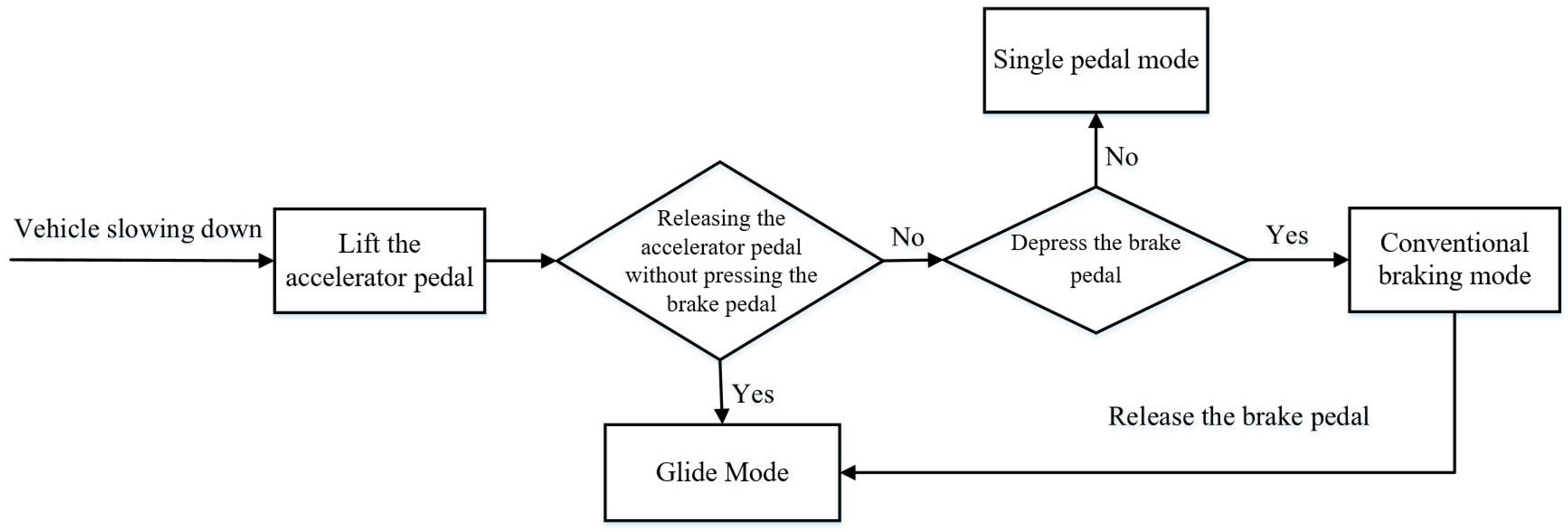
The vehicle’s energy recovery system switches to conventional braking mode when the driver depresses the brake pedal. Under traditional braking, the braking force required by the vehicle is generally categorized into four types: small braking force, small and medium braking force, medium and large braking force, and large braking force. To ensure the safety and stability of the vehicle braking process, the braking force provided by the motor brake can only meet the small braking force situation. In contrast, the small and medium braking forces, medium and large braking forces, and large braking forces all need to participate in the hydraulic brake.
According to the I curve (see Section 2.3.1 (1)), ECE regulation curve (see Section 2.3.1 (2)), f line group (see Section 2.3.1 (3)), and coordinate axis to determine the safe braking region, the region has fully considered the braking theory, regulatory requirements, vehicle driving and braking energy recovery efficiency, and other factors; so, it can ensure braking safety and stability while improving braking energy recovery.
2.3.1. Front and Rear Axle Brake Force Distribution
- (1)
- Ideal front and rear axle brake force distribution I-curve:
In battery electric vehicles, in the braking dead process, the vehicle’s front and rear wheels will appear in three situations: (1) the front wheels first hold dead drag slip, followed by the rear wheels, and then hold dead; (2) the rear wheels first hold dead drag slip, followed by the front wheels, and then hold dead; (3) the front and rear wheels at the same time hold dead.
When the wheels appear, the front wheels first hold dead slippery; although the vehicle’s front wheels hold dead and lose steering ability, this situation can still ensure the stability of the braking; when the rear wheels first hold dead slippery, although the front wheels do not hold dead, they can still steer but are prone to the tailgate out of control phenomenon; when the vehicle’s braking force and its adhesion are equal to the wheel on the road surface, the coefficient of adhesion of the utilization of the maximum at this point. Not only can it ensure the steering ability of the vehicle, but it can also ensure the safety and stability of braking.
During the braking of the vehicle, the vehicle is subjected to the force of gravity and the vertical reaction force of the front and rear axles, and the force balance equation in the vertical direction is as follows:
where is the ground normal reaction force on the front wheels, is the ground normal reaction force on the rear wheels, is the mass of the vehicle, and is the acceleration of gravity.
This can be obtained by analyzing the forces at the tangent points of the front and rear wheels to the ground:
where is the distance from the center of mass to the front axle of the vehicle; is the distance from the center of mass to the rear axle of the vehicle; is the acceleration of the vehicle; and is the height of the center of mass of the vehicle.
The braking strength z is as follows:
The ground force on the front and rear wheels of the vehicle during braking can be obtained after association as follows:
where is the force of the ground on the front wheel and is the force of the ground on the rear wheel. is the braking strength.
In the actual driving process of the vehicle, the braking of the vehicle is also related to the adhesion coefficient of the driving surface. In different adhesion coefficients of the road surface, the vehicle’s braking force on the front and rear wheels should meet the following formula:
where φ is the pavement adhesion coefficient.
In vehicles in the braking process, when the front and rear wheels of the vehicle are simultaneously on hold on the road surface, adhesion coefficient utilization is the largest, which can ensure the stability and safety of the vehicle when braking. Accordingly, it can be obtained as follows:
In the above equation, and are the braking forces for the front and rear axles of the vehicle, respectively.
In summary, the expression for the ideal I-curve can be obtained as follows:
- (2)
- ECE regulation front brake force distribution requirement curve:
The ECE R13 regulation is an essential regulatory standard for vehicle braking systems. It specifies the technical requirements and test methods for vehicle braking devices to ensure the vehicles’ safety, reliability, and performance in terms of braking meet specific standards. The regulation provides detailed technical specifications and standards for designing, manufacturing, and testing vehicle braking systems. It aims to ensure the safety and performance of vehicles in braking meet specific standards and improve driving safety. It is a high reference for the regulation’s significance.
The ECE R13 braking regulations require that the front wheels utilize the position of the coefficient of adhesion curve to be above the rear wheels, which utilize the coefficient of adhesion curve; the vehicle front and rear wheel braking force coefficient of adhesion curves, as well as braking strength and road friction coefficients between the expressions, are as follows [25]:
where is the braking strength, is the front wheel attachment coefficient, is the rear wheel attachment coefficient, and is the road friction coefficient.
The equation for the front and rear wheel braking force curves for the ECE braking regulations can be obtained by association as follows:
The collation gives the ECE R13 regulatory limit curve equation as follows:
- (3)
- The f-line set brake force distribution requirement curve:
The f-line group is the vehicle with different coefficients of adhesion road braking; the rear wheels are not locked, while the front wheels are locked. On the front wheel braking force relationship curve, the front wheels should be locked to meet the formula [21]:
where is the vehicle’s front brake force and is the vehicle’s rear brake force, , which, when brought into the above equation, gives the line group equation as follows:
To synthesize the joint road surfaces and their coefficients of adhesion in daily driving, take 
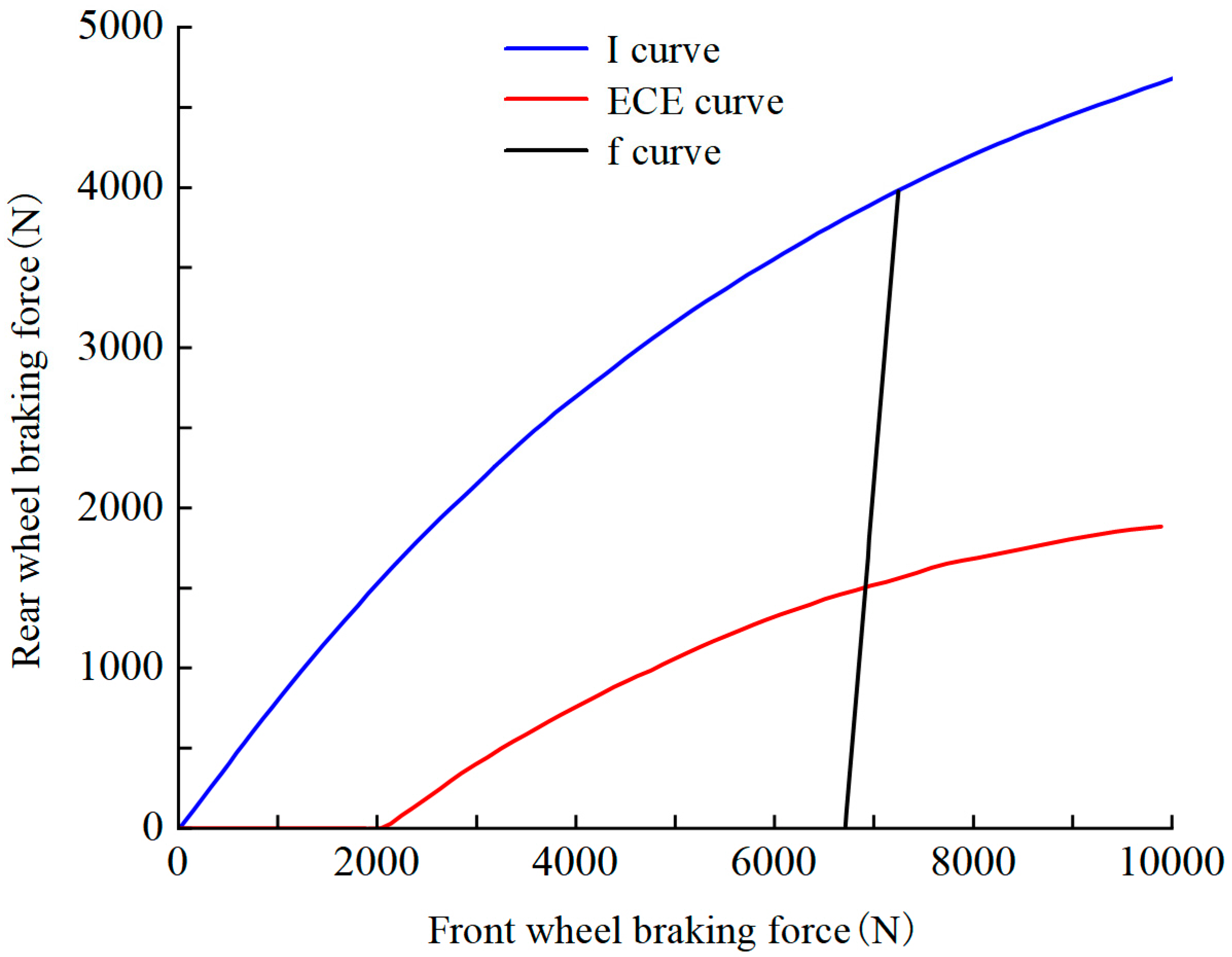
. In summary, to ensure the safety and stability of vehicle braking, the vehicle’s front and rear axle braking force distribution should be carried out in the closed interval surrounded by the I-curve, the f-line group, and the ECE regulation restriction curve, as shown in Figure 4.
Figure 4.
I-curves, f-line sets, ECE regulation limit curves.
As can be seen from Figure 4, when the braking intensity is a slight braking force demand, the rear axle braking force is zero, and the braking force is all assigned to the front axle. At this point, one can obtain the vehicle braking front and rear axle braking force and braking strength of the relationship between these, which, when brought into the calculation, can be derived as = 0.125:
When , at this time, for small and medium braking power demand, the calculation can be obtained as = 0.525. When 0.125 < z ≤ 0.525, the front and rear axle braking power along the curve of the AB section for the distribution, and the vehicle front and rear axle braking power should meet the following formula:
When , there is a medium-large braking force demand, which, through the calculation, can be derived as = 0.7. When 0.525 < z < 0.7, the front and rear axle braking forces are distributed along the f-line (BC section). At this time, the vehicle’s front and rear axle braking forces are as follows:
where is the slope of the straight line of the BC section, and and are the front and rear axle braking forces at point C, respectively.
When , z ≥ 0.7, the vehicle is in emergency braking condition, the front and rear axle braking forces are distributed according to the I curve (CD section), and the vehicle front and rear axle braking forces should satisfy the following equation:
In summary, the vehicle’s front and rear axle braking force distribution during conventional brake energy recovery is as follows:
(1) When 0 < z ≤ 0.125, the vehicle needs less braking power; the front and rear axle braking power is distributed along the OA section of the curve, and the braking power is distributed to the front axle, provided by the motor. Brake energy recovery is performed to charge the HV battery when the battery’s SOC value and vehicle speed meet the conditions.
(2) When 0.125 < z ≤ 0.525, the vehicle needs medium–low-intensity braking power, the braking power of the front and rear axles is distributed along the curve AB, and under the premise of ensuring braking safety and stability, hydraulic braking is the auxiliary braking power, and as much braking power as possible is distributed to the front axle motor braking for energy recovery.
(3) When 0.525 < z < 0.7, the vehicle needs medium–high-intensity braking force. The front and rear axle braking forces are now distributed along the curve BC section. To ensure braking safety and stability, the braking force is mainly provided by the hydraulic brake; at the same time, the motor brake takes into account the recovery of braking energy.
(4) When z ≥ 0.7, this time for emergency braking conditions, the vehicle needs high-strength braking force to stop as soon as possible. The front and rear axle braking power is distributed along the curve CD section, provided by hydraulic braking power.
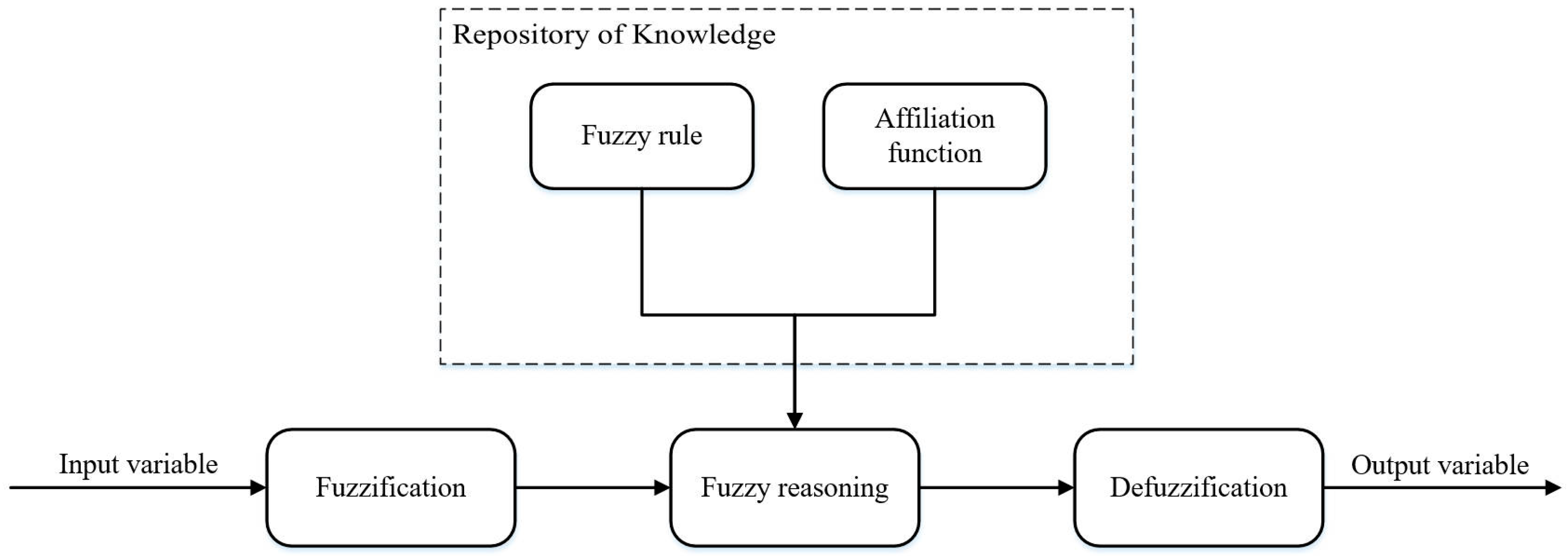
2.3.2. Power Distribution Strategy for Fuzzy Controlled Motorized Mechanisms in Conventional Mode
The braking energy recovery allocation ratio is related to the braking intensity z, vehicle initial speed v, and HV battery’s SOC value. To ensure the safety and stability of vehicle braking, the braking energy recovery allocation ratio should be gradually reduced with a gradual increase in vehicle speed. When the battery SOC reaches the threshold value of 90%, the braking energy recovery function is turned off to prevent overcharging, and the braking intensity is proportional to the braking energy recovery allocation ratio.
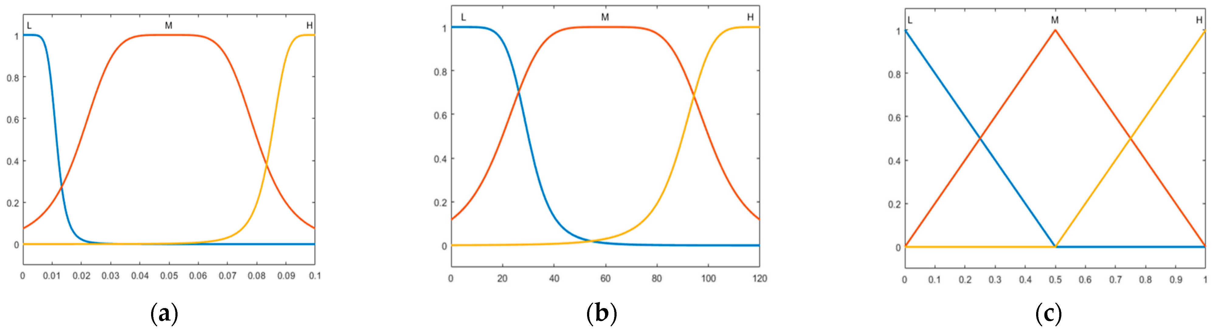
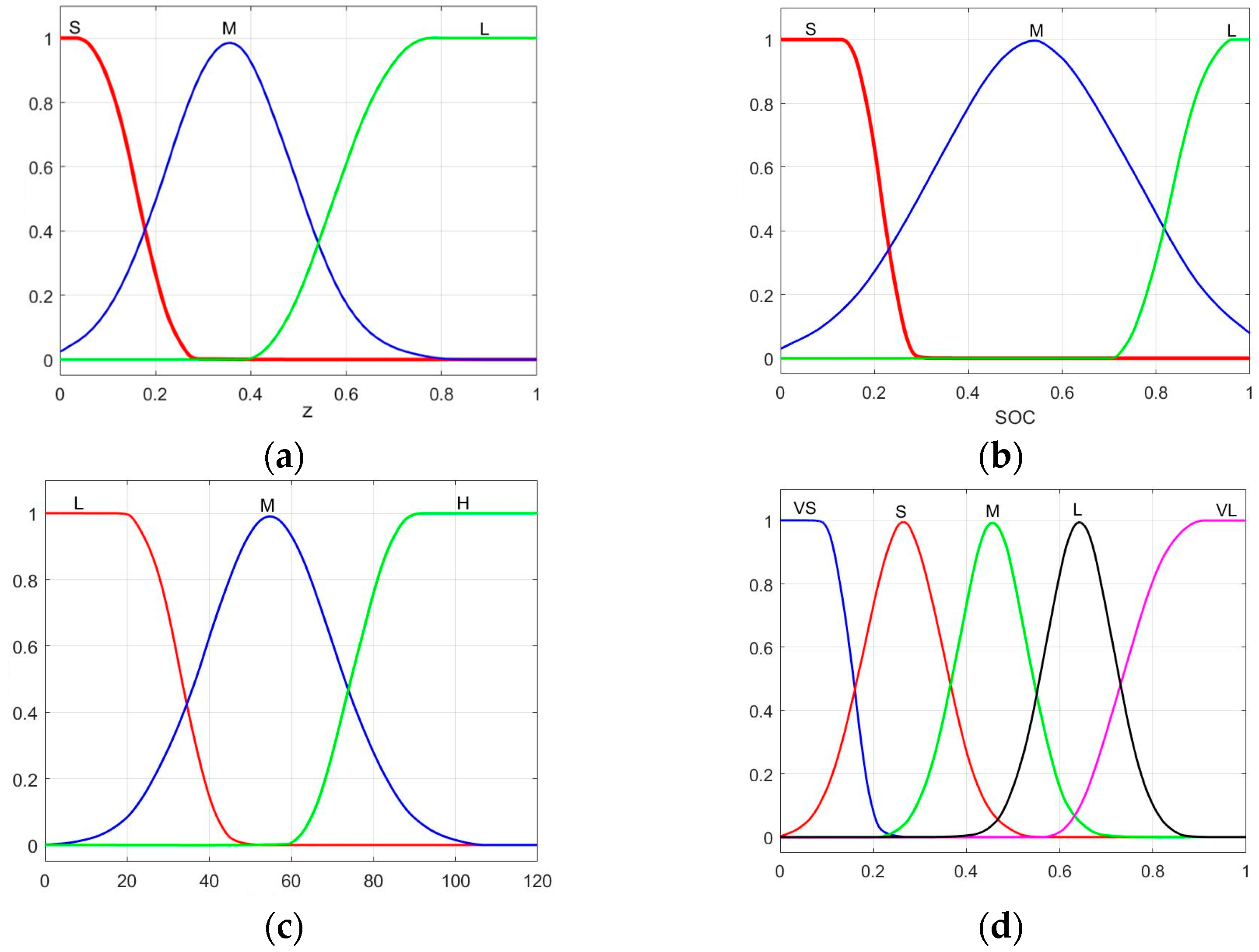
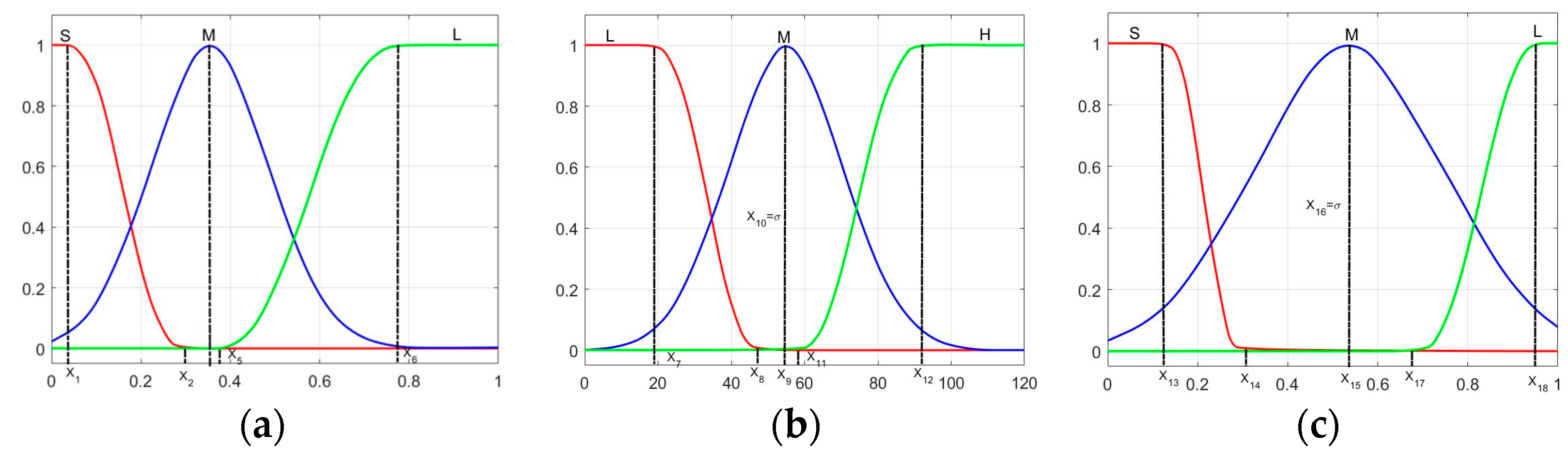
Among them, the domain of the input variable brake strength is [0, 1], the genus function S is selected as the ZMF (Z Membership Function) type, M is selected as the GAUSSMF (Gaussian Membership Function) type, L is selected as the SMF (S Membership Function) type, and the distribution is shown in Figure 5a. The domain of the battery’s SOC is [0, 1], the genus function S (Small) is chosen as the ZMF type, M (Medium) is chosen as the GAUSSMF type, L (Large) is chosen as the SMF type, and the distribution is shown in Figure 5b. The speed domain is [0, 120], the genus function M is selected as the GAUSSMF type, the genus function H is selected as the SMF type, and the distribution is shown in 
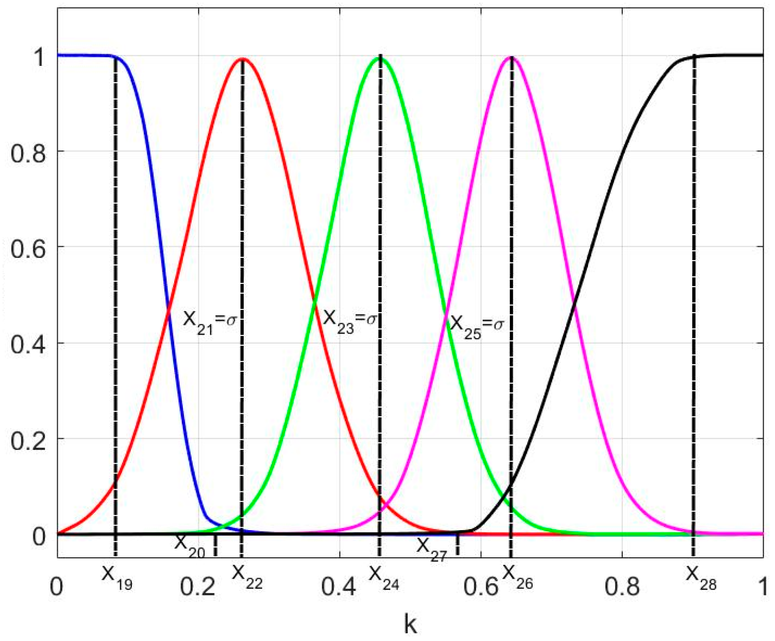
Figure 5c. The domain of the output variable motorized power ratio k is [0, 1], and the affiliation function VS (Very small) is selected as the ZMF type. S, M, and L are selected as GAUSSMF types. VL (Very large) is chosen as the SMF type; the distribution is shown in Figure 5d.
Figure 5.
The plot of fuzzy control affiliation function: (a) brake strength affiliation function; (b) battery SOC relative function; (c) velocity dependence function; (d) motor braking proportional affiliation function.
The fuzzy controller has three input variables, braking strength z, battery power SOC, and vehicle speed v; and one output variable, the proportion of motorized power k. The fuzzy subsets of the input variable, braking strength z, are defined as {S, M, L}, which stand for {small, medium, and large}. The fuzzy defined subsets of the battery power SOC are defined as {S, M, L}, which stand for {low, medium, and high power}, respectively; The fuzzy subset of vehicle speed v is defined as {L, M, H}, which represents {low, medium, high}; the output variable is the power distribution coefficient k of the motor mechanism, and the fuzzy subset is defined as {VS, S, M, L, VL}, which represents {very small, small, medium, large, and very large}. A total of 27 fuzzy rules are formulated, as shown in Table 2.
Table 2.
Conventional braking mode fuzzy rule table.
2.3.3. Control Strategy for Energy Recovery of Coasting Brake
This study of coasting brake energy recovery control strategy is divided into two scenarios: horizontal road coasting and downhill road coasting.
- (1)
- Brake energy recovery control strategy for horizontal road skidding:
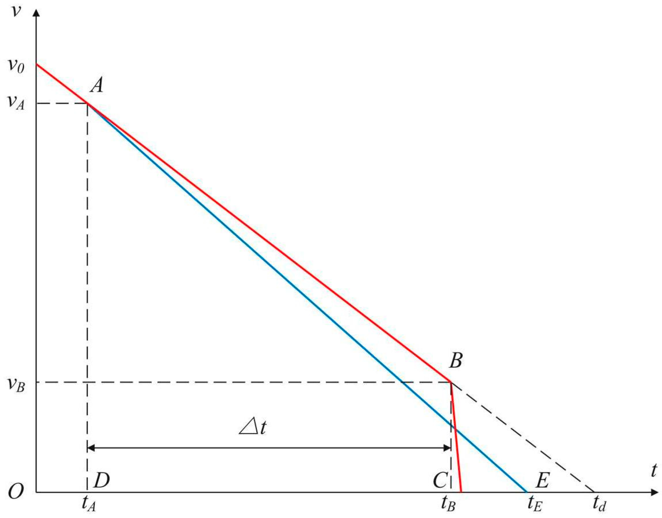
Figure 6 shows the analysis of the vehicle coasting mode. The red line in the figure is the coasting curve of the vehicle, and when energy recovery is not added, it can be seen that the driver gradually releases the accelerator pedal from the initial speed, and when it reaches point A, the vehicle speed is , leading it to start coasting. When reaching point B, the vehicle speed is . The driver steps on the brake pedal to stop the vehicle. The blue line in the figure is the vehicle’s coasting curve after joining the coasting brake’s energy recovery, starting from point A to enter the coasting and energy recovery, until point E, where the vehicle stops.
Figure 6.
Vehicle skidding mode analysis diagram.
From the above analysis, the deceleration of the vehicle when the vehicle does not incorporate energy recovery is and the deceleration of the vehicle when it incorporates energy recovery is . Based on the forces on the vehicle, the following formula can be obtained:
The expression for can be deduced from the slope as follows:
The equation can be derived when the glide displacement is the same in both scenarios:
Bringing in DC, one can solve for DE:
The expression for is as follows:
In summary, the expression for the power of the motor mechanism can be obtained as :
According to the constraints on the brake energy recovery control strategy in Section 2.1 of this paper, the motor will only recover brake energy when the system detects that both the brake pedal and accelerator pedal are not operated for 2 s. Therefore, it is 2 s. In addition, the amount of motor power supplied by the motor is also limited by the restrictions imposed by the ECE regulations and the motor’s external characteristic curves. Therefore, it can be deduced that the motor outputs braking power in the horizontal road scenario as follows:
- (2)
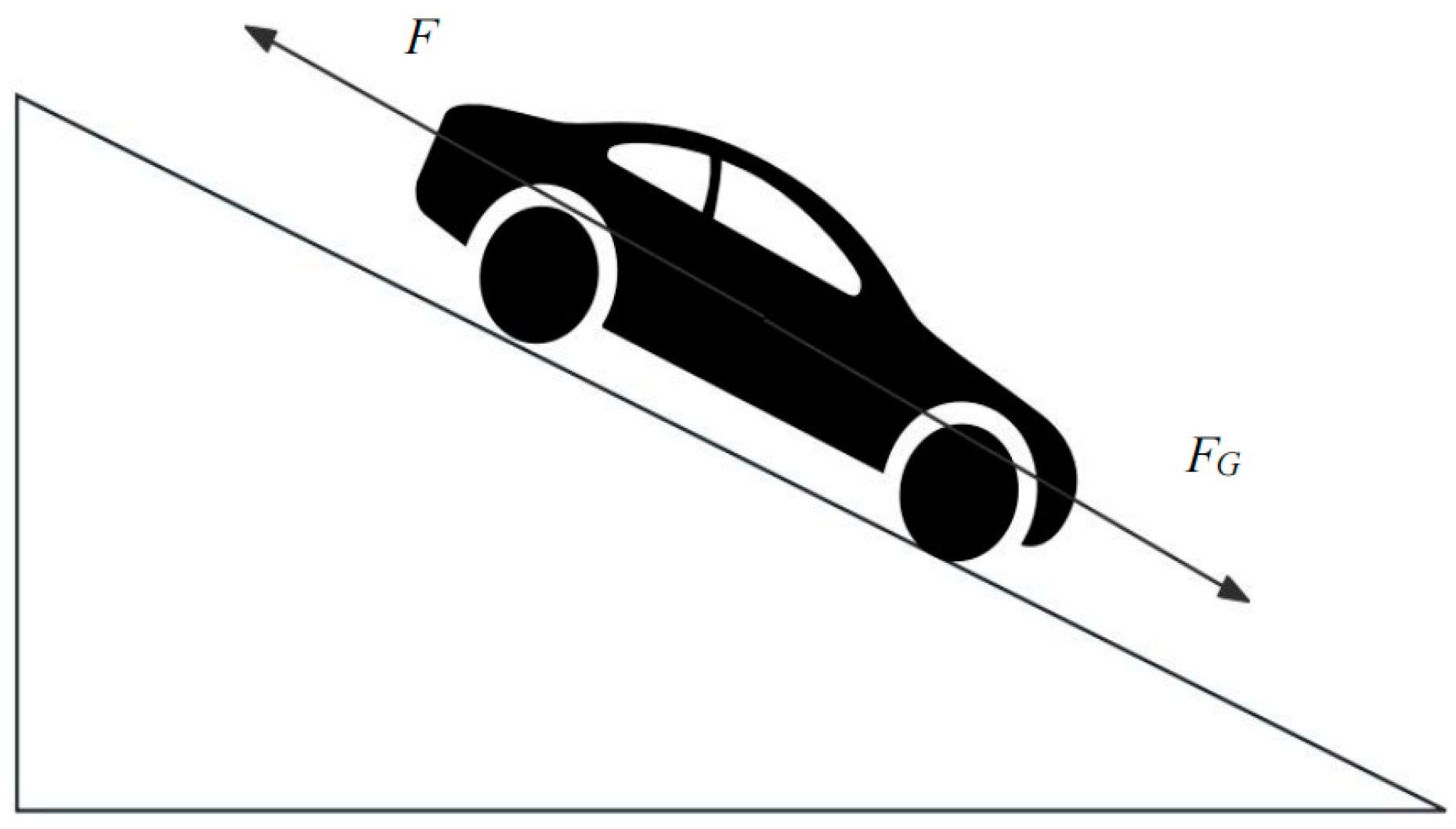
- Brake energy recovery control strategy for downhill road coasting:
Figure 7 shows the force analysis of the vehicle during the downhill coasting scenario; is the component force of the car’s gravity, and F is the combined driving resistance force (air resistance, rolling resistance, etc.) on the car. Set the slope angle as . The ECE braking regulations front and rear wheel braking force curve equation changes to the formula shown in Equation (34):
Figure 7.
Vehicle downhill force analysis diagram.
The acceleration of the vehicle downhill at this point is as follows:
where is the terminal velocity of the vehicle skidding, is the initial velocity of the vehicle skidding, is the acceleration of the vehicle skidding, and is the vehicle skidding time.
To achieve a uniform speed downhill, after the driver releases the brake pedal and accelerator pedal, the motor is first allowed to output a fixed motor mechanism power to decelerate along with the driving resistance, and the initial and final speeds of the vehicle skidding in a short period are determined. The vehicle force at this time is as follows:
where is the resistance of the vehicle, is the component force of gravity of the vehicle in the direction of travel, and electricity is the fixed electric mechanism power provided by the motor.
The braking force required for the vehicle to achieve a uniform downhill speed is as follows:
Setting to 0.9 times the initial speed of the driver when he releases the brake and accelerator pedals, the simplification gives the required braking force for the final downhill scenario as follows:
3. Optimization of Control Strategies Based on Genetic Algorithms
Although fuzzy control can better deal with nonlinear variable problems, the formulation of the affiliation function and fuzzy rules in fuzzy control is too dependent on the knowledge and experience of experts in the field. Although the formulated affiliation function and fuzzy rules can be applied to the established fuzzy controllers, they still have certain limitations. Moreover, the number of input and output variables in fuzzy control may increase dramatically with the increase in system complexity, which leads to the design and debugging of the affiliation function and fuzzy rules becoming more complicated. The conventional braking mode has the highest frequency of use and braking energy recovery in daily driving. Therefore, the fuzzy controller designed in the traditional braking energy recovery mode is optimized by introducing a genetic algorithm to recover as much energy as possible to ensure stable and safe braking in the conventional braking mode.
3.1. Principles of Genetic Algorithms
Genetic algorithms take the chromosome coding of the optimization object as the object and carry out iterative optimization search through the genetic operation with speculative genetic algorithms in the iterative process, generally through the chromosome coding, population initialization, fitness function design, genetic operation, and control parameter design of five processes [26,27,28].
- (1)
- Chromosome coding: Chromosome coding is a prerequisite for updating the iteration of a genetic algorithm. Each set of solutions of the optimization object is regarded as a chromosome when coding, and each feature of the solution is viewed as a gene on the chromosome. Converting the feature data of the optimization object into a chromosome composed of genes is the coding process.
- (2)
- Population initialization: After the coding method is determined, the string structure data is generated by a random function to represent the individual population, and the specific number of the population is determined by the size of the data set of the optimization object, and the initialization of the population can be carried out in the range of the distribution of the globally optimal solution in the space when the distribution range of the global optimal solution in the space is determined.
- (3)
- Design of fitness function: The central role of the fitness function is to determine the individual’s adaptation to the environment, to distinguish the advantages and disadvantages of the individuals in the population, the probability of survival of the individual in the population is positively correlated with the adaptation to the environment, and the fitness function is mainly defined according to the objective function of the optimization object.
- (4)
- Genetic operation: Genetic operation mainly includes selection, crossover, and mutation. Selection is based on the fitness function value, by the corresponding rules, from the parent group to select the better individuals to generate offspring individuals. Crossover is the process of two paired chromosomes exchanging alleles to produce two new chromosomes. Mutation is the process by which genes on a chromosome change into other alleles according to the probability of mutation.
- (5)
- Control parameter: The control parameter mainly sets the conditions for the algorithm’s termination. When the algorithm updates the iteration number to reach the maximum parameter set or the difference in the fitness function of each generation reaches the allowable error range, the genetic algorithm stops running and outputs the optimal solution.
3.2. Genetic Algorithm for Fuzzy Controller Optimization
Currently, there are three standard optimization methods for fuzzy controllers: one is to optimize the formulated fuzzy rules; the second is to optimize the fuzzy control input and output variables’ affiliation functions; and the third is to optimize both simultaneously. In this paper, the second optimization method is used to iteratively optimize the affiliation functions of the input and output variables. The optimization process is shown in Figure 8.
Figure 8.
Fuzzy control optimization process.
- (1)
- Selection of optimization variables
This paper mainly selects the optimization variables based on the characteristic parameters of the fuzzy controller’s affiliation function, which refer to each affiliation function’s inflection points and boundary points. The input variables of the fuzzy controllers designed in the conventional brake energy recovery control strategy use ZMF-, GAUSSMF-, and SMF-type affiliation functions. Equation (39) shows the expression of the GAUSSMF-type affiliation function, which has two characteristic parameters of mean = 0.5 and standard deviation = 0.2.
Equation (40) and Equation (41) are expressions for ZMF-type and SMF-type affiliation functions, respectively, with two characteristic parameters, a and b, for ZMF-type and two characteristic parameters, c and d, for SMF-type.
The ZMF-type affiliation function expression is as follows [29]:
The SMF-type affiliation function expression is as follows:
Since all three input variables of the fuzzy controller use ZMF-type, GAUSSMF-type, and SMF-type affiliation functions, respectively, there are six optimization parameters for each input variable, totaling 18 optimization parameters. The location of the optimization variables for each input affiliation function is selected, as shown in Figure 9.
Figure 9.
Input optimization variable position selection: (a) brake strength affiliation function optimization variables; (b) vehicle speed affiliation function optimization variables; (c) SOC affiliation function optimization variables.
Fuzzy controller output variables using a ZMF-type, three GAUSSMF-type, and an SMF-type affiliation function for ten optimized variables. The output variable affiliation function optimized variable position selection, as shown in Figure 10.
Figure 10.
Output optimization variable position selection.
In summary, 28 optimization variables were selected from the input and output variables. After the optimization variables are chosen, the value range of each optimization variable is constrained to avoid excessive cross-overlapping between different fuzzy subset affiliation functions, and the value range of optimization variables is shown in Table 3.
Table 3.
Optimization variable value range table.
- (2)
- Chromosome code
The standard coding methods are binary coding and floating-point coding. Binary coding is due to mapping errors in the discretization, resulting in the iterative search for the optimal space becoming larger so that the performance and efficiency of the algorithm optimization are reduced. Therefore, this paper uses the floating-point coding method to encode the optimization variables. The length of the encoding is the same as the number of variables, and the encoding formula is as follows [30]:
where is the optimization variable; is the minimum value of the optimization variable; is the maximum value of the optimization variable, is a random number between [0, 1]; and is the gene position on the chromosome.
- (3)
- Design of the fitness function
The genetic algorithm’s fitness function measures the degree to which the individuals in the population are close to the global optimal solution to the problem. The fitness function usually varies from the optimization objective function, which converts the objective function value to the fitness value of the individuals in the genetic search formula.
The main effect of using a genetic algorithm to optimize the fuzzy controller is to improve the braking energy recovery rate; so, the objective function value is selected as the braking energy recovered during braking. In this paper, the calculation of the braking energy recovery value under NEDC cycling conditions is carried out according to the battery power output from the coupled Cruise vehicle model in the Simulink control strategy model, and the expression is as follows:
- (4)
- Design of the fitness function
The standard methods of selection operation are the proportional selection method, random traversal sampling method, truncated selection method, and random selection without replay margin, etc. In this paper, the proportional selection method is selected. The principle of this method is that the probability of a population individual being inherited by the next generation is directly proportional to its fitness. Let the population size be , the fitness of individual be , and then the probability of an individual being selected is as follows:
From the above equation, the higher the fitness of the optimized individual, the higher the probability of being selected. However, since the algorithm is based on comparing the randomly generated probability and the likelihood of the individual being assigned to determine whether the individual is selected, its randomness may lead to the excellent individual not being selected. In response to this situation, the proportional selection method is improved to a random selection with no replay residual, and the specific operation process is as follows:
(1) Calculate the expected number of inheritances of an individual in the parent’s generation in the offspring with the formula:
(2) Take the integer part [] of as the genetic number when the total number of individuals in the offspring is .
(3) The new fitness of individuals in the parent generation is calculated according to Equation (47) and based on the proportional selection method to determine the individuals in the offspring population that have not yet been identified.
Crossover operation is when the crossover operation can generate the individual in the parent generation to generate new individuals and increase the local search ability of the genetic algorithm. To carry out the crossover operation, the chromosomes in the parent population must be paired two by two, and then the alleles are exchanged according to the rules. This paper uses floating-point coding to conduct the crossover operation between the two chromosomes. The formula is as follows:
(4) The mutation operation is a process that simulates the replacement of a gene mutation on a chromosome by another allele. Suppose a gene on a chromosome has a value range of [,]. In that case, the mutation operation is to replace the original value of the gene with another value in that value range, and the mutation operation is performed by selecting a non-uniform mutation. Let the chromosome be mutated at the point where the gene at the end of mutation has a value range of [,], and the formula for the value of the gene after mutation is as follows:
The non-uniform variant searches similarly to the uniform variant in the initial run phase. In contrast, in the later run phase, the focus is on performing searches under minor variations in the local focus area. Thus, as the algorithm runs, the non-uniform variant concentrates the search on the desired, focused local regions.
(5) Genetic algorithm control parameters
The control parameters mainly refer to the length of the coding string, the evolutionary algebra of the algorithm, the population size, the crossover probability, and the mutation probability. The control parameters directly affect the genetic algorithm’s solving speed, efficiency, and structure. The length of the coding string in floating-point coding and the number of optimization variables are consistent with 28. The population size generally takes the value range of 20–50, and 30 population sizes are selected according to the actual conditions.
The crossover probability generally ranges from 0.4 to 0.99. If the value is too large, it will destroy the excellent group. If the value is too small, it will slow the speed of generating new individuals, and 0.7 is selected as the crossover probability.
The mutation probability is generally taken as 0.01–0.1. The genetic algorithm will only be random if the value is manageable. If the value is too small, the inhibition effect will be weaker. The average value of the interval 0.055 is chosen as the mutation probability.
The number of evolutionary generations determines the end condition of optimization; when the update iteration to the maximum number of generations, optimization will end, generally taking the value of 50–1000, and according to the actual conditions, set the number of iterations to 50 times.
After the genetic algorithm is optimized, the affiliation function’s input and output variables are shown in Figure 11. After the genetic algorithm optimization of the best optimization variables, the value of Table 4 is taken.

Figure 11.
Optimized affiliation function: (a) optimized brake strength affiliation function; (b) optimized SOC affiliation function; (c) brake strength affiliation function optimization variables; (d) vehicle speed affiliation function optimization variables.
Table 4.
Table of values for the best optimization variables.
4. Co-Simulation and Analysis of Results
This paper is based on the joint simulation of AVL-Cruise and Matlab/Simulink R2021b software. The battery electric vehicle model is built with AVL-Cruise R2019.2 software, and the brake energy recovery control strategy model is built with Matlab/Simulink R2021b software. The joint simulation analysis is based on NEDC and CLTC-P, two cyclic working conditions.
4.1. Modeling
4.1.1. Battery Electric Vehicle Model Construction
This paper uses Cruise R2019.2 software to establish the battery electric vehicle model. The whole vehicle model of a battery electric vehicle is shown in Figure 12, which mainly includes the vehicle module, driver module, wheel module, motor module, battery module, and so on. Among them, the central role of the strategy module is to realize the joint simulation with the dll file inputted by Matlab R2021b software.
Figure 12.
Battery electric vehicle models.
The specific parameters of the whole vehicle, the battery electric vehicle, are shown in Table 5. The basic parameters of the motor that need to be input in the motor module include the motor’s operating voltage, maximum power, maximum speed, the motor’s external characteristic curve, and other parameters, and the specific parameters are shown in Table 6. The basic parameters to be entered in the battery module include the SOC value of the battery, the capacity of a single battery, the rated voltage of the battery, the rated capacity of the battery, etc. The specific parameters of the battery are shown in Table 7.
Table 5.
Basic parameters of battery electric vehicles.
Table 6.
Basic parameters of the drive motor.
Table 7.
Basic parameters of the battery.
4.1.2. Brake Energy Recovery Control Strategy Modeling
After completing the battery electric vehicle modeling in Cruise R2019.2 software, the brake energy recovery control strategy model is built in Matlab/Simulink R2021b software.
The control strategy model obtains input variables such as brake pedal opening, maximum braking torque of the braking system, speed ratio of the speed reducer, current vehicle speed, speed of the drive motor, SOC of the HV battery, opening of the accelerator pedal, current discharging power of the battery, etc., from the Cruise R2019.2 software. After the established control strategy model is output to Cruise R2019.2 software, the front axle brake system torque, rear axle brake system torque, motor demand torque, and so on, are obtained.
4.2. Cruise and Matlab/Simulink Co-Simulation Analysis
4.2.1. Cyclic Condition Simulation
NEDC (New European Driving Cycle) and CLTC-P (China Light-duty Vehicle Test Cycle-Passenger) were simulated test conditions.
The NEDC cycle runs for 1180 s, consisting of four urban cycles and one suburban cycle, while the CLTC-P cycle consists of three intervals of low, medium, and high speeds, with a cycle running time of 1800 s. Figure 13 shows the speed following curves of the NEDC and CLTC-P conditions, respectively, showing that the established EV models can follow the desired speeds well, and follow the desired speed for the two different working conditions.
Figure 13.
Vehicle speed the following curve for two working conditions: (a) NEDC speed tracking curve for operating conditions; (b) CLTC-P operating speed tracking curve plot.
- (1)
- NEDC cycle conditions
The initial SOC of the HV battery is set to 80%, and the end SOC is set to 10%. The comparison of the range under NEDC conditions is shown in Figure 14. From the figure, it can be seen that the vehicle’s range is lowest when the power recovery control strategy is not added, which is 233 km; the range under the single-mode brake energy recovery control strategy is significantly increased, with a range of 325 km and a range contribution rate of 39.5%; after adding the multi-mode brake energy recovery control strategy proposed in this paper, the range is significantly increased, with a range of 347.5 km, and the range mileage contribution rate is 49.1%. Compared with the single-mode brake energy recovery control strategy, the range contribution rate is increased by 9.6%, the range is increased by 22.5 km, and the range is increased by 114.5 km compared with the no-brake energy recovery control strategy.
Figure 14.
NEDC operating range comparison chart.
Figure 15 shows the SOC value curve change under NEDC conditions, from which it can be seen that the battery electric vehicle can effectively improve the vehicle range after adding the brake energy recovery control strategy. Before the start of the cycle, the initial value of the HV battery SOC is 80%. After the end of the cycle, it can be seen that the SOC value under the multi-mode brake energy recovery control strategy is 77.76%, which is higher than the 77.68% under the single-mode brake energy recovery control strategy and is significantly higher than the 76.88% of the no-brake energy recovery control strategy.
Figure 15.
SOC change curve of NEDC working condition.
Figure 16 show the energy recovery and consumption graph under NEDC conditions. It can be seen that the single-mode brake energy recovery control strategy recovers 1918 kJ of energy and outputs 7197 kJ of energy, with a brake energy recovery rate of 26.6%. In contrast, the multi-mode brake energy recovery control strategy recovers 2299 kJ of energy and outputs 7526 kJ, with a brake energy recovery rate of 30.6%. However, the output of energy from the multi-mode brake energy recovery control strategy is slightly higher than that of the single-mode control strategy. Although the output energy of the multi-mode brake energy recovery control strategy is somewhat higher than that of the single-mode brake energy recovery control strategy, the brake energy recovery rate is increased by 4% compared with the single-mode control strategy.
Figure 16.
NEDC operating condition energy change curve.
- (2)
- CLTC-P cycle condition
Again, the initial SOC of the HV battery is set to 80%, the end SOC is set to 10%, and the depth of discharge is 80%. A comparison of the range under the CLTC-P condition is shown in Figure 17. From the figure, it can be seen that the vehicle’s range is lowest when the power recovery control strategy is not added, which is 238 km; the range under the single-mode brake energy recovery control strategy is significantly increased, with a range of 324 km and a range contribution rate of 36.1%; after adding the multi-mode brake energy recovery control strategy proposed in this paper, the range is significantly increased, with a range of 337 km, and a range The contribution rate is 41.9%; compared with the single-mode brake energy recovery control strategy, the contribution rate of the range is increased by 5.5%, the range is increased by 13 km, and the range is increased by 99 km compared with the no-brake energy recovery control strategy; so, it can be seen that the effect of the multi-mode brake energy recovery control strategy is significant.
Figure 17.
CLTC-P operating range comparison chart.
Figure 18 shows the change in the SOC value curve under CLTC-P condition, from which it can be seen that after adding brake energy recovery control to the battery electric vehicle, the SOC curve is still locally increasing. However, it is generally decreasing, which can effectively improve the range. Before the start of the cycle, the initial value of the HV battery SOC is 80%. After the end of the simulation, the SOC value under the multi-mode brake energy recovery control strategy is 76.98%, which is higher than 76.91% under the single-mode brake energy recovery control strategy and significantly higher than 75.6% under the no-brake energy recovery control strategy.
Figure 18.
SOC change curve of CLTC-P working condition.
Figure 19 show the energy recovery and consumption graphs for the CLTC-P operating conditions. It can be seen that the single-mode brake energy recovery control strategy recovers 3330 kJ of energy and outputs 10,470 kJ of energy, with a brake energy recovery rate of 31.8%. The multi-mode brake energy recovery control strategy recovers 4696 kJ of energy and outputs 11,590 kJ of energy, with a brake energy recovery rate of 40.5%. The brake energy recovery rate is increased by 8.7% compared to the single-mode control strategy. The brake energy recovery rate is improved by 8.7% compared to the single-mode control strategy.
Figure 19.
CLTC-P operating condition energy change curve.
Combining the above simulation and verification results of two different working conditions of NEDC and CLTC-P, the multi-mode braking energy recovery control strategy proposed in this paper can significantly improve the efficiency of the braking energy recovery rate and increase the vehicle’s range.
4.2.2. Genetic Algorithm Optimization Simulation
A genetic optimization algorithm is written in Matlab/Simulink R2021b software to optimize the conventional brake energy recovery control strategy, and a joint simulation is carried out in Cruise R2019.2 software based on the NEDC cycle conditions. The written genetic optimization algorithm mainly includes chromosome coding function, chromosome feasibility test function, selection operation function, crossover operation function, mutation operation function, and fitness calculation function.
Figure 20 shows the optimized energy recovery curve of the genetic algorithm. As can be seen from the figure, when the algorithm iterates to 16 generations after the function value reaches the maximum, it no longer changes. The average value of the individual population of each generation changes with the increase in the number of iterations to the optimal function value and these gradually overlap, which fully demonstrates the effectiveness of genetic algorithms for the optimization of conventional brake energy recovery control strategy and ultimately in the NEDC cycle conditions, leading to an output of the braking energy recovery of 2299 kJ.
Figure 20.
Optimization of energy recovery curves by genetic algorithms.
The energy recovered by the motor under NEDC cycling conditions without optimization using the algorithm is 2050 kJ, which is lower than the amount of braking energy recovered from the output of the fuzzy controller optimized using the genetic algorithm. The specific data are shown in Table 8.
Table 8.
Maximum recovered energy comparison.
The simulation analysis of the genetic optimization algorithm shows that adding a genetic algorithm to optimize the fuzzy controller in the conventional braking energy recovery mode can effectively increase the amount of energy recovered from the conventional braking of the battery electric vehicle and improve its range.
5. Conclusions
This paper proposes a multi-mode switching brake energy recovery control strategy based on fuzzy control to improve the energy recovery efficiency of battery electric vehicles and increase the range of the vehicles, taking battery electric vehicles as the research object. The proposed control strategy includes three brake energy recovery modes, single-pedal, conventional braking, and coasting, and uses the accelerator pedal and brake pedal signals as the switching conditions between modes so that the vehicle can switch to different modes in real time according to the driving conditions. In the single-pedal mode and conventional braking mode, the electric and hydraulic braking forces are distributed by fuzzy control. A genetic algorithm is added to iteratively optimize the affiliation function of the fuzzy control in the conventional braking mode, which effectively improves the recovered braking energy. Under the premise of ensuring safe and stable braking, the energy generated during braking is recovered as much as possible to improve the range of the vehicle.
Through the joint simulation analysis of Cruise R2019.2 software and Matlab/Simulink R2021b software, the braking energy recovery rate is 30.6%. The range contribution rate is 49.1% under the NEDC cycle, which is 4% and 9.6% higher than that of the single-mode braking energy recovery control strategy, and the range increases by 22.5 km and 114.5 km compared with the no-braking energy recovery control strategy. In the CLTC-P cycle, the brake energy recovery rate is 40.5%. The range contribution rate is 41.6%, 8.7%, and 5.5% higher than the single-mode brake energy recovery control strategy. The range is increased by 13 km compared with the single-mode brake energy recovery control strategy. After adding the genetic optimization algorithm, the energy recovered in regular braking mode is 2299 kJ, 249 kJ more than the energy recovered without algorithm optimization. In summary, the proposed multi-mode brake energy recovery control strategy based on fuzzy control can further improve battery electric vehicles’ braking energy recovery efficiency. Braking energy recovery efficiency can effectively increase battery electric vehicles’ range.
The control strategy proposed in this paper was only co-simulated with software to verify its effectiveness. However, the strategy’s actual effectiveness has yet to be verified. Therefore, future work will further validate the control strategy’s applicability to actual vehicles.
Author Contributions
Conceptualization, B.L. and G.L.; methodology, B.L.; software, S.W. and B.L.; validation, B.L. and G.L.; formal analysis, B.L.; investigation, S.W.; resources, G.L.; data curation, S.W.; writing—original draft preparation, B.L.; writing—review and editing, B.L. and G.L.; visualization, B.L. and S.W.; supervision, G.L.; project administration, G.L.; funding acquisition, G.L. and B.L. All authors have read and agreed to the published version of the manuscript.
Funding
This work was supported by the General Program of the Natural Science Foundation of Liaoning Province in 2022 (2022-MS-376) and the Natural Science Foundation joint fund project (U22A2043).
Institutional Review Board Statement
Not applicable.
Informed Consent Statement
Not applicable.
Data Availability Statement
The raw data supporting the conclusions of this article will be made available by the authors on request.
Conflicts of Interest
The authors declare that they have no conflicts of interest.
References
- Pennycott, A.; Novellis, L.D.; Gruber, P.; Sorniotti, A. Optimal braking force allocation for a four-wheel drive fully electric vehicle. Proc. Inst. Mech. Eng. Part I J. Syst. Control Eng. 2014, 228, 621–628. [Google Scholar] [CrossRef]
- Guo, J.; Dong, H.; Sheng, W.; Tu, C. Optimum control strategy of regenerative braking energy for electric vehicle. Jiangsu Univ. Nat. Sci. Ed. 2018, 39, 132–138. [Google Scholar] [CrossRef]
- Ahmed, T.H.; Mehmet, F.O. An overview of regenerative braking systems. J. Energy Storage 2022, 52, 105033. [Google Scholar] [CrossRef]
- Liang, J.; Walker, P.D.; Ruan, J. Gearshift and brake distribution control for regenerative braking in electric vehicles with dual clutch transmission. Mech. Mach. Theory 2019, 133, 1–22. [Google Scholar] [CrossRef]
- Li, Y.; Wu, Z.; Lv, W. Optimisation of braking energy recovery for rear-drive electric vehicles based on fuzzy control. Int. J. Veh. 2023, 92, 2–4. [Google Scholar] [CrossRef]
- Ji, F.; Pan, Y.; Zhou, Y.; Du, F.; Zhang, Q.; Li, G. Energy recovery based on pedal situation for regenerative braking system of electric vehicle. Veh. Syst. Dyn. 2019, 58, 144–173. [Google Scholar] [CrossRef]
- Debasri, C.; Arup, K. Finding optimal deceleration with serial regenerative braking of electric vehicle using a multi-objective genetic algorithm. In Proceedings of the 2016 IEEE 1st International Conference on Power Electronics, Intelligent Control and Energy Systems (ICPEICES), Delhi, India, 4–6 July 2016; pp. 1–6. [Google Scholar] [CrossRef]
- Liu, Z.; Liu, Z.; Lu, S.; Du, R. A genetic-fuzzy control method for regenerative braking in electric vehicle. Int. J. Comput. Sci. Math. 2020, 11, 263–277. [Google Scholar] [CrossRef]
- Gao, Y.; Chen, L.; Ehsani, M. Investigation of the Effectiveness of Regenerative Braking for EV and HEV. SAE Trans. 1999, 108, 3184–3190. Available online: http://www.jstor.org/stable/44733986 (accessed on 5 May 2024).
- Gao, Y.; Mehrdad, E. Electronic Braking System of EV And HEV Integration of Regenerative Braking, Automatic Braking Force Control and ABS. SAE Trans. 2001, 110, 576–582. [Google Scholar] [CrossRef]
- Gao, Y.; Chu, L.; Ehsani, M. Design and Control Principles of Hybrid Braking System for EV, HEV and FCV. In Proceedings of the 2007 IEEE Vehicle Power and Propulsion Conference, Arlington, TX, USA, 9–12 September 2007; pp. 384–391. [Google Scholar] [CrossRef]
- Gao, H.; Gao, Y.; Ehsani, M. A neural network based SRM drive control strategy for regenerative braking in EV and HEV. In Proceedings of the IEEE International Electric Machines and Drives Conference, Cambridge, MA, USA, 17–20 June 2001; pp. 571–575. [Google Scholar] [CrossRef]
- Li, J.; Jin, X.; Xiong, R. Multi-objective optimization study of energy management strategy and economic analysis for a range-extended electric bus. Energy Policy 2017, 194, 798–807. [Google Scholar] [CrossRef]
- Zhao, B.; Liu, R.; Shi, D.; Li, S.; Cai, Q.; Shen, W. Optimal Control Strategy of Path Tracking and Braking Energy Recovery for New Energy Vehicles. Processes 2022, 10, 1292. [Google Scholar] [CrossRef]
- Khaled, I.; Alexandre, D.B.; Zoubir, K. Comparison between two braking control methods integrating energy recovery for a two-wheel front driven electric vehicle. Energy Convers. Manag. 2016, 122, 330–343. [Google Scholar] [CrossRef]
- Xu, S.; Li, J.; Zhang, X.; Song, J.; Zeng, X. Research on Composite Braking Control Strategy of Four-Wheel-Drive Electric Vehicles with Multiple Motors Based on Braking Energy Recovery Optimization. IEEE Access 2023, 11, 110151–110163. [Google Scholar] [CrossRef]
- Chang, J.; Zhang, Y. Optimization of braking energy recovery control strategy for pure electric vehicles based on EMB. Automot. Eng. 2022, 44, 64–72. [Google Scholar] [CrossRef]
- Ma, Z.; Sun, D. Energy Recovery Strategy Based on Ideal Braking Force Distribution for Regenerative Braking System of a Four-Wheel Drive Electric Vehicle. IEEE Access 2020, 8, 136234–136242. [Google Scholar] [CrossRef]
- Li, X. Simulation Analysis of Fuzzy Control Strategy for Braking Energy Recovery of a Pure Electric Vehicle. Int. J. New Dev. Eng. Soc. 2023, 7, 60–65. [Google Scholar] [CrossRef]
- Tian, Q.; Cheng, H. Regenerative braking energy recovery control strategy for electric vehicles with battery temperature measurement. J. Phys. Conf. Ser. Int. 2023, 2584, 12–34. [Google Scholar] [CrossRef]
- Wang, Q.; Zhang, L.; Liu, X.; Li, Y.; Wang, Y.; Zhang, Y. Braking Energy Recovery of Pure Electric Vehicles with Compound Control Strategy. In Proceedings of the 2023 6th International Conference on Computer Network, Electronic and Automation (ICCNEA), Xi’an, China, 22–24 September 2023; pp. 296–300. [Google Scholar] [CrossRef]
- Park, Y.; Park, S.; Ahn, C. Performance Potential of Regenerative Braking Energy Recovery of Autonomous Electric Vehicles. Int. J. Control Autom. Syst. 2023, 21, 1442–1454. [Google Scholar] [CrossRef]
- Yin, Z.; Ma, X.; Su, R.; Huang, Z.; Zhang, C. Regenerative Braking of Electric Vehicles Based on Fuzzy Control Strategy. Processes 2023, 11, 2985. [Google Scholar] [CrossRef]
- Ashok, B.; Kannan, C.; Deepak, C.; Ramesh, R.; Narendhra, T.M.; Farrag, M.E.; Ashok, S.D.; Vignesh, R.; Saiteja, P.; Kavitha, C. Model based integrated control strategy for effective brake energy recovery to extend battery longevity in electric two wheelers. Proc. Inst. Mech. Eng. Part D J. Automob. Eng. 2023. [Google Scholar] [CrossRef]
- Li, S.; Yu, B.; Feng, X. Research on braking energy recovery strategy of electric vehicle based on ECE regulation and I curve. Sci. Prog. 2020, 103, 36850419877762. [Google Scholar] [CrossRef] [PubMed]
- Kong, D.; Miyatake, M. Cooperative Application of Onboard Energy Storage and Stationary Energy Storage in Rail Transit Based on Genetic Algorithm. Energies 2024, 17, 1426. [Google Scholar] [CrossRef]
- Sun, C.; Chu, L.; Guo, J.; Shi, D.; Li, T.; Jiang, Y. Research on adaptive cruise control strategy of pure electric vehicle with braking energy recovery. Adv. Mech. Eng. 2017, 9, 1–12. [Google Scholar] [CrossRef]
- Wu, T.; Wang, F.; Ye, P. Regenerative Braking Strategy of Dual-Motor EV Considering Energy Recovery and Brake Stability. World Electr. Veh. J. 2023, 14, 19. [Google Scholar] [CrossRef]
- Chen, J.; Zhu, H.; Zhang, L.; Sun, Y. Research on fuzzy control of path tracking for underwater vehicle based on genetic algorithm optimization. Ocean Eng. 2018, 156, 217–223. [Google Scholar] [CrossRef]
- Poursamad, A.; Montazeri, M. Design of genetic-fuzzy control strategy for parallel hybrid electric vehicles. Control Eng. Pract. 2008, 16, 861–873. [Google Scholar] [CrossRef]
Disclaimer/Publisher’s Note: The statements, opinions and data contained in all publications are solely those of the individual author(s) and contributor(s) and not of MDPI and/or the editor(s). MDPI and/or the editor(s) disclaim responsibility for any injury to people or property resulting from any ideas, methods, instructions or products referred to in the content. |
© 2024 by the authors. Licensee MDPI, Basel, Switzerland. This article is an open access article distributed under the terms and conditions of the Creative Commons Attribution (CC BY) license (https://creativecommons.org/licenses/by/4.0/).