Article

Design of Robust Broadband Frequency-Invariant Broadside Beampatterns for the Differential Loudspeaker Array

1
Anhui Digital Intelligent Engineering Research Center for Agricultural Products Quality Safety, Fuyang Normal University, Fuyang 236037, China
2
Anhui Province Photovoltaic Industry Common Technology Research Center, Fuyang Normal University, Fuyang 236037, China
3
Faculty of Engineering and IT, University of Technology, Sydney, NSW 2007, Australia
*
Author to whom correspondence should be addressed.
Appl. Sci. 2024, 14(14), 6383; https://doi.org/10.3390/app14146383
Submission received: 13 June 2024 / Revised: 18 July 2024 / Accepted: 19 July 2024 / Published: 22 July 2024
(This article belongs to the Special Issue Noise Measurement, Acoustic Signal Processing and Noise Control)

Abstract

:
The directional loudspeaker array has various applications due to its capability to direct sound generation towards the target listener and reduce noise pollution. Differential beamforming has recently been applied to the loudspeaker line array to produce a broadside frequency-invariant radiation pattern. However, the existing methods cannot achieve a compromise between robustness and broadband frequency-invariant beampattern preservation. This paper proposed a robust broadband differential beamforming design to allow the loudspeaker line array to radiate broadside frequency-invariant radiation patterns with robustness. Specifically, we propose a method to determine the ideal broadside differential beampattern by combining multiple criteria, namely null positions, maximizing the directivity factor, and achieving a desired beampattern with equal sidelobes. We derive the above ideal broadside differential beampattern into the target beampattern in the modal domain. We propose a robust modal matching method with Tikhonov regularization to optimize the loudspeaker weights in the modal domain. Simulations and experiments show improved frequency-invariant broadside beamforming over the 250–4k Hz frequency range compared with the existing modal matching and null-constrained methods.

1. Introduction

Directional loudspeaker arrays have attracted the attention of researchers because of their promising applications in spatial audio reproduction [1,2], public address systems [3,4], and personal sound zone creation [5,6]. The most commonly used directional loudspeaker arrays are additive arrays. Additive arrays generate highly directional beampatterns by controlling the interference of the waves generated by multiple loudspeakers. However, due to the diffraction limit, small-sized additive arrays cannot radiate highly directional beampatterns at low frequencies [7].
In contrast, differential arrays with small aperture sizes can overcome the diffraction limit to generate and radiate a narrow beampattern. Due to their compact size, frequency-invariant beampattern, and high spatial directivity, differential arrays have been studied intensively in microphone array applications over the past two decades. Many different ·geometries of differential microphone arrays have been developed and studied, such as linear [8,9,10,11,12,13,14], planar [15,16,17,18,19], and volumetric [20,21,22,23]. Differential beamforming of linear arrays has been extensively studied, but most research sets the main lobe at the end-fire direction [8,9,11,13]. Although some studies investigate beam steering for linear arrays, their beam steering capability is quite limited [10,14]. Planar arrays, such as circular arrays [17,19] or concentric circular arrays [15,16,18], can effectively solve the beam steering issue of linear arrays, allowing for arbitrary steering within the plane of the array. Volumetric arrays, such as cube arrays [20,21,23] and spherical arrays [22], can produce consistent sound acquisition performance in the three-dimensional space. However, the required large number of microphones and huge array volume hinders its applications in some scenarios.
Because of the reciprocity principle of the acoustic field, the differential beamformers have also been applied to loudspeaker arrays to produce highly directional patterns [7,24,25,26,27,28,29]. The differential loudspeaker array is significant for the field of acoustics and sound technology, offering a novel approach to improving directional sound quality in various applications such as sound reinforcement systems [24,26,29], spatial sound reproduction [27], and personal sound zones [25,28]. Choi used a second-order broadside differential loudspeaker array with three elements to create a near-field sound zone in a car cabin [25]. Wang et al. devised a null-constrained method to generate a higher-order broadside differential beampattern [26]. This approach is convenient for designing differential beamformers in real applications. However, the frequency-invariant beampattern may only be maintained over part of the frequency range due to the constraints imposed only at several discrete directions. Miltello et al. designed a steerable first-order differential beampattern using a small-size loudspeaker line array with monopole and dipole elements [28]. Our recent research studied the series expansion method for designing frequency-invariant beampatterns using a loudspeaker array [27,29]. In [27]. we design steerable beampattern using a circular loudspeaker array. This method requires prior knowledge of the target beampattern, which may not be feasible in real-world applications. We also proposed a method to design broadside beampattern using a differential loudspeaker line array [29]. We first derived the modal domain target to beampattern the nulls’ information. Then, it employed modal matching with Jacobi–Anger expansion and distortionless constraint (MM-JAD) to approximate the target beampattern, which led to better-preserved frequency-invariant beampatterns across the frequency range of interest, such as the speech frequency range.
This paper proposed a robust broadband differential beamforming design to allow the loudspeaker line array to radiate broadside frequency-invariant radiation patterns with robustness. The main contributions are as follows. (1) We propose a method to calculate the ideal broadside beampattern combining various criteria, namely, null information, maximizing the directivity factor, and achieving the beampattern with equal sidelobes. (2) We derive the modal domain target beampattern of a given ideal broadside differential beampattern. (3) We propose a robust modal matching method with Tikhonov regularization to design the broadside beamformer in the modal domain.
The remainder of this paper is organized as follows. Section 2 presents the signal model, problem formulation, and some definitions. In Section 3, we propose a method to design broadside frequency-invariant beampatterns with a line array in the modal domain. Some simulations are presented in Section 4, including some design examples, along with a discussion about the effect of regularization on the proposed method and a performance comparison with the other existing beamforming methods. Section 5 gives the experimental results, which are consistent with the simulations, validating the proposed method. Finally, conclusions are given in Section 6.

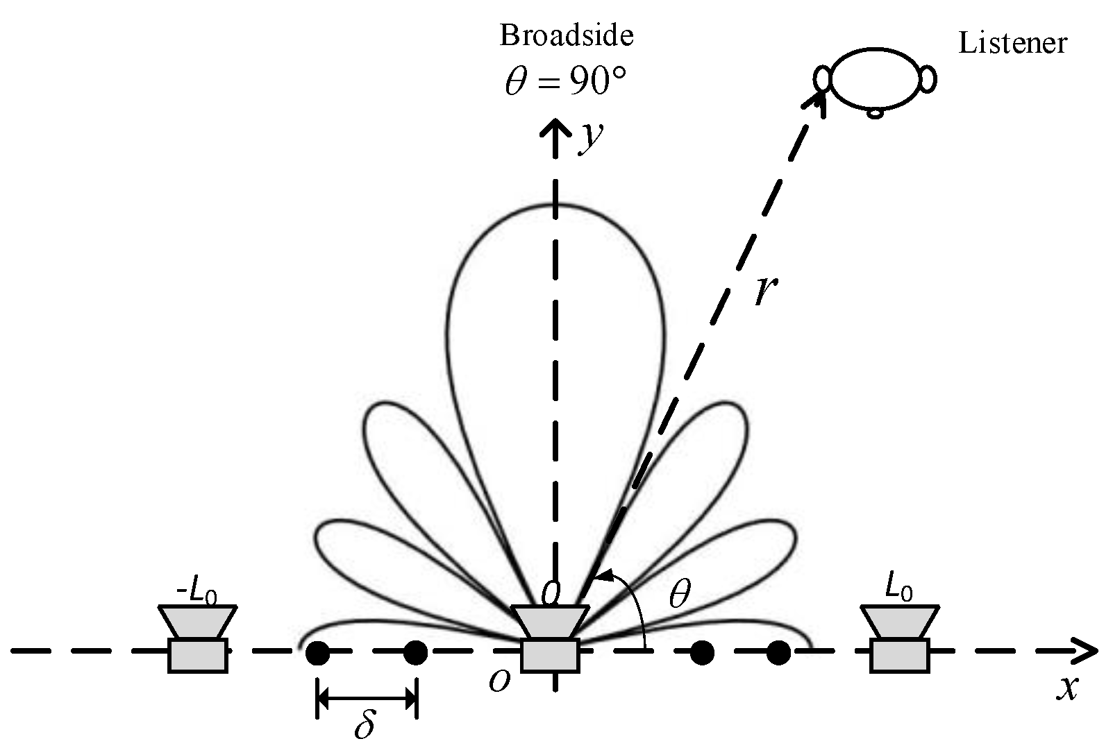
2. Problem Formulation

Figure 1 shows the schematic diagram of a loudspeaker line array with its broadside differential beampattern. A loudspeaker line array composed of L (L = 2L0 + 1, L0  1) equally spaced loudspeakers with a spacing of δ lies on the x axis. The array is centred at the origin of the polar coordinate system. Assuming that each loudspeaker of the array is a monopole source, the far-field sound pressure at a listener position ( r , θ ) is
p ( k , r , θ ) e i k r 4 π r l = L 0 L 0 w l * ( k ) e i k x l cos θ
where k is the wave number, the superscript ( ) stands for the complex-conjugate operator, w l ( k ) represents the weight of l-th loudspeaker at ( x l , 0 ) , where x l = l δ is the loudspeaker index l [ L 0 , L 0 ] .
For the directivity of radiation, we define the normalized far-field radiation pattern as
B ( k , θ ) = p ( k , r , θ ) / ( e i k r / 4 π r ) = l = L 0 L 0 w l * ( k ) e i k x l cos θ ,
which can be expressed in a vector form
B ( k , θ ) = w H g ( k , θ )
where the superscript ( ) H is the conjugate-transpose operator
w = [ w L 0 ( k ) , , w L 0 ( k ) ] T
g ( k , θ ) = [ e i k x L 0 cos θ , , e i k x L 0 cos θ ] T
The superscript ( ) T is the transpose operator and w is the weighting vector to be determined.
The white noise gain (WNG) can represent the radiation efficiency of a loudspeaker array and is often used as a robustness measure.
WNG = | B ( k , π / 2 ) | 2 w H w
The directivity factor (DF) quantifies the directional property. The 2D-DF can be defined as the ratio between the power radiated in the broadside direction and the spatial average of the radiated intensity over the half plane where the loudspeaker array is located.
DF = π | B ( k , π / 2 ) | 2 0 π | B ( k , θ ) | 2 d θ = | B ( k , π / 2 ) | 2 w H Γ w
where
Γ = 1 π 0 π g H ( k , θ ) g ( k , θ ) d θ
is a square matrix, whose elements are [ Γ ] i j = J 0 ( k ( i j ) δ ) . J 0 ( ) is the zero-order Bessel function of the first kind.
The directivity index (DI) represents the directivity factor (DF) on a log scale.
DI = 10 log 10 ( DF )

3. Methods

We propose an approach based on the series expansion method to design a broadside frequency-invariant beampattern with a differential loudspeaker line array in the modal domain, including (1) calculating the target broadside radiation pattern according to multiple criteria, namely null positions, maximizing the directivity factor, and achieving a desired beampattern with equal sidelobes, and (2) designing the differential beamformer using the regularized modal matching method.

3.1. Target Broadside Radiation Pattern

3.1.1. Target Broadside Radiation Pattern with the Null Information

Assuming the spacing between neighboring loudspeakers to be much smaller than the wavelength, the ideal 2Nth-order broadside differential beampattern can be expressed as
B ˜ ( 2 N ) ( θ ) n = 1 N ( 1 cos 2 θ β n 2 )
where the superscript ( ) ( 2 N ) denotes the 2Nth-order; N is a positive integer; the parameters β n , n = 1, 2, …, N, determine the N null directions in the range of 0 to π / 2 , where θ N , n null = arccos β n and 0 < θ N , 1 null θ N , 2 null θ N , N null < π / 2 . Note that to ensure the effectiveness of the target broadside beampattern, θ N , N null must be less than π / 2 π / ( 4 N ) [30]. It should be also pointed out that in order to generate the 2N-th target beampattern, at least 2N + 1 loudspeakers are required.
With the help of the nth elementary symmetric function definitions [31], (10) can be written in a sum form:
B ˜ ( 2 N ) ( θ ) = n = 0 N α N , n cos 2 n θ
where
α N , n = {             1                   n = 0 ( 1 ) n 1 i 1 < i 2 < i n N 1 β i 1 2 β i n 2 , n = 1 , , N .

3.1.2. Target Broadside Radiation Pattern with Maximum Directivity Factor

The 2N-th order broadside differential beampattern in (11) can be written in vector form
B ˜ ( 2 N ) ( θ ) = α N T c 2 N
where
α N = [ α N , 0 α N , 1 α N , N ] T c 2 N = [ 1 cos 2 θ cos 2 N θ ] T
Inserting (13) into the definition of directivity factor in (7) yields
DF = π α N T C α N
where B ( k , θ ) is replaced with B ˜ ( 2 N ) ( θ ) and
C = 0 π c 2 N c 2 N T d θ
To obtain the 2N-th order broadside differential beampattern with maximum directivity factor, the optimization problem can be formulated as follows:
min α N α N T C α N
It is easy to verify that
α N T C α N = 1 + α ˜ N T C ˜ α ˜ N + 2 c ˜ T α ˜ N
where
{ c ˜ = [ cos 2 θ cos 2 N θ ] T α ˜ N = [ α N , 1 α N , N ] T C ˜ = 0 π c ˜ c ˜ T d θ
The (m,n)th element of the matrix C ˜ is written as
C ˜ m n = 0 π cos 2 ( m + n ) θ d θ = ( 2 m + 2 n 1 ) ! ! π ( m + n ) ! 2 m + n     ( m , n = 1 , , N )
where ( · ) ! ! is the double factorial and ( · ) ! is the factorial.
The optimization problem (17) can be equivalently written as
min α ˜ N α ˜ N T C ˜ α ˜ N + 2 c ˜ T α ˜ N
The optimal real vector α ˜ N can be solved by using the method of Lagrange multipliers
α ˜ N = C ˜ 1 c ˜
The optimal real vector α N can be written as
α N = [ 1 α ˜ T N ] T

3.1.3. Target Broadside Radiation Pattern with Equal Sidelobe Level

An Nth-order Chebyshev polynomial of the first kind with respect to the variable can be defined as [11]
T N ( z ) = { cos ( N cos 1 z ) , | z | 1 cosh ( N cosh 1 z ) , | z | > 1
Substituting z with a cos 2 θ + b , T N ( z ) becomes a 2N-th order polynomial with respect to cos θ and the 2N-th order broadside beampattern that follows the Chebyshev polynomial is formed. The main lobe at θ = π / 2 corresponds z 1 = b . The value of the Chebyshev polynomial is
T N ( z 1 ) = cosh ( N cosh 1 b )
The sidelobe at θ = 0 , z 0 = a + b , and we obtain
T N ( z 0 ) = 1
Corresponding to
z 0 = a + b = 1
Setting S is the main lobe to sidelobe ratio, we have
S = T N ( z 1 ) T N ( z 0 ) = cosh ( N cosh 1 b )
Combing (27) and (28), we obtain
b = cosh ( 1 N cosh 1 S ) a = 1 cosh ( 1 N cosh 1 S )
Since the zeros of the Chebyshev polynomial are easily found, the nulls of the broadside Chebyshev beampattern are
θ N , n n u l l = arccos ( cos ( ( 2 n 1 ) π / ( 2 N ) ) b a ) , n = 1 , 2 , , N .
Figure 2 shows some examples of target broadside radiation pattern designed by the methods mentioned above. Figure 2a gives the second-order target broadside radiation pattern with the given nulls at 15° and 165°. Figure 2b shows the fourth-order ideal beampattern with nulls at 15°, 45°, 135°, and 165°. Figure 2c,d illustrate the second-order and fourth-order broadside differential pattern with maximum directivity factor. Figure 2e,f show the fourth-order ideal radiation pattern for the −10 dB and −20 dB sidelobes, respectively.

3.2. Beamformer Design

If the 2N-th target broadside beampattern is given, (11) can also be formulated in the modal domain with a symmetric form
B ( 2 N ) ( k , θ ) = n = 2 N 2 N γ n e i n θ
where
γ n = { 0 , n = ± 1 , ± 3 , , ± ( 2 N 1 ) , p = | n | / 2 N α N , p 2 2 p ( 2 p p | n | / 2 ) , n = 0 , ± 2 , ± 4 , , ± 2 N .
where ( . . ) is combinations, and | | represents absolute value. With the vector form
B ( 2 N ) ( k , θ ) = γ T e ( θ )
where
γ = [ γ 2 N γ 2 N ] T
e ( θ ) = [ e i 2 N θ e i 2 N θ ] T
In the series expansion method, the Jacobi–Anger expansion is used to match the resulting beampattern to the target beampattern in (31). The Jacobi–Anger expansion is
e i ξ cos θ = n = + β n ( ξ ) e i n θ
where
β n ( ξ ) = ( i ) n J n ( ξ ) .
is the circular harmonic coefficient and J n ( ) is the nth-order Bessel function of the first kind.
Appling (36) into the exponential of (2) yields
B ( k , θ ) = l = L 0 L 0 w l * ( k ) n = + β n ( k x l ) e i n θ
In order to obtain a 2Nth-order broadside target radiation pattern, the infinite series is truncated to the order 2N:
B ( k , θ ) = n = 2 N 2 N e i n θ l = L 0 L 0 β n ( k x l ) w l * ( k ) .
If the radiation pattern in (39) is consistent with the target beampattern in (31), one can obtain
l = L 0 L 0 β n ( k x l ) w l * ( k ) = γ n   n = 0 , ± 1 , , ± 2 N
For the design of a broadside differential beamformer, the distortionless constraint in the broadside direction is required:
w H g ( k , π / 2 ) = 1
Combing (40)–(41),
Φ w = η
where
Φ = [ β 2 N β 2 N g ( k , π / 2 ) ] H
β n = [ β n ( k x L 0 ) β n ( k x L 0 ) ] T
η = [ γ T 1 ] T
With the fact that β n ( ) = β n ( ) and (32), one can obtain
Φ ˜ w = η ˜
where
Φ ˜ = [ β 0 β 2 N g ( k , π / 2 ) ] H
is ( 2 N + 2 ) × L full-rank matrix
η ˜ = [ γ ˜ T 1 ] T
where γ ˜ = [ γ 0 γ 2 N ] T is the coefficients of the desired beampattern. With the number loudspeakers L > 2 N + 2 , the minimum-norm solution of (46) is
w = Φ ˜ H ( Φ ˜ Φ ˜ H ) 1 η ˜
To deal with the ill-posed inverse problems existing in (49), Tikhonov regularization is used to calculate the minimum-norm solution,
w = Φ ˜ H ( Φ ˜ Φ ˜ H + μ I 2 N + 2 ) 1 η ˜
where μ is the regularization parameter, which is a preselected non-negative number to enhance robustness.

4. Simulations

In this section, we evaluate the performance of the proposed method with a loudspeaker line array. The target beampattern is the 2Nth-order broadside differential beampattern with maximized directivity factor whose beampattern coefficients are calculated by the methods mentioned in Section 3.1.2. The frequency range of interest is from 250 Hz to 4 kHz, covering the frequency range of speech.

4.1. The 2Nth-Order Broadside Differential Beamformer Synthesized by the Proposed Method

Different orders of the target broadside differential beampattern with maximized directivity factor are synthesized by the solution (50) using a line array of 31 loudspeakers with a spacing of 0.038 m. We first set the regularization parameter μ to a small non-negative number, 10 12 , and then study the effect of this parameter on the beamformer.
The synthesized beampatterns are shown in Figure 3. Different orders of broadside radiation patterns can be synthesized by the modal matching method with Tikhonov regularization. Except for the slight deviation in the null positions at some frequency points, the beamformer gives the frequency-invariant beampattern almost across the evaluated frequency range. The reason for the nulls’ deviation is that, unlike the null-constrained method which adds constraints at the null positions, the proposed method approximates the desired beam in the modal domain. The finite truncation in (39) results in the spatial aliasing with higher-order circular harmonics. To solve this problem, a higher truncation order of the Jacobi–Anger expansion should be considered [32].
The WNG and DI are two important metrics in beamforming algorithms. The WNG is a good indicator of the robustness to element imperfections. The DI quantifies the directional property. Figure 4 shows the performance of different-order beampatterns synthesized by the proposed method in terms of WNG and DI. As can be seen in Figure 4a, the WNGs of the different-order beamformers tend to be consistent above 1 kHz, all exhibiting relatively high WNG values, which indicate that the proposed method is robust enough at high frequencies. At low frequencies, the higher the order of the target beampattern synthesized, the lower the WNG obtained. It indicates that the eighth-order broadside differential beamformer has the worst anti-perturbation ability below 1 kHz. Figure 4b shows the DIs of different order beamformers designed by the proposed method. As seen, the DI increases with the order of the synthesized beampattern. Except for some fluctuations at certain frequencies, which coincide with the conclusion of Figure 3, the DIs of all four kinds of beamformers can approximately maintain a constant at all evaluated frequencies.

4.2. Effect of the Regularization on the Proposed Method

The regularization parameter has an impact on the performance of the beamformer. To demonstrate this, we compare the WNGs and DIs of the sixth-order synthesized beamformer with different regularization parameters. The WNGs and DIs are plotted in Figure 5. As seen in Figure 5a, in the frequency range above 1 kHz, the WNG does not change with the increase in μ , indicating that there is no ill-conditioned problem existing in solving the optimal weighting and the solution is robust at high frequencies. Below 1 kHz, the larger the value of μ , the more frequency points have the WNG above 0 dB. When μ equals 10 12 , the WNGs are below −20 dB at some frequency points, indicating the beamformer has poor anti-perturbation ability. When μ equals 0.01, the WNG is above 0 dB above 300 Hz, which is considered robust enough for practical applications. Figure 5b shows the impact of the regularization parameter on the DI. As seen, the regularization parameter mainly affects the DI of the proposed method at low frequencies. Below 1 kHz, as the regularization parameter increases, the fluctuation amplitude of the DI increases. This indicates that the improvement of the WNG at low frequencies comes at the cost of increased fluctuation of the DI. Additionally, it is noted that, at high frequencies, the DI corresponding to μ equals 0.01, which is slightly higher than the DI when μ is set to a smaller value. This indicates that a larger regularization parameter, although affecting the frequency-invariant characteristic of the beampattern at low frequencies, improves the proposed method’s robustness at low frequencies and slightly enhances the directivity performance at high frequencies.

4.3. Performance Comparison

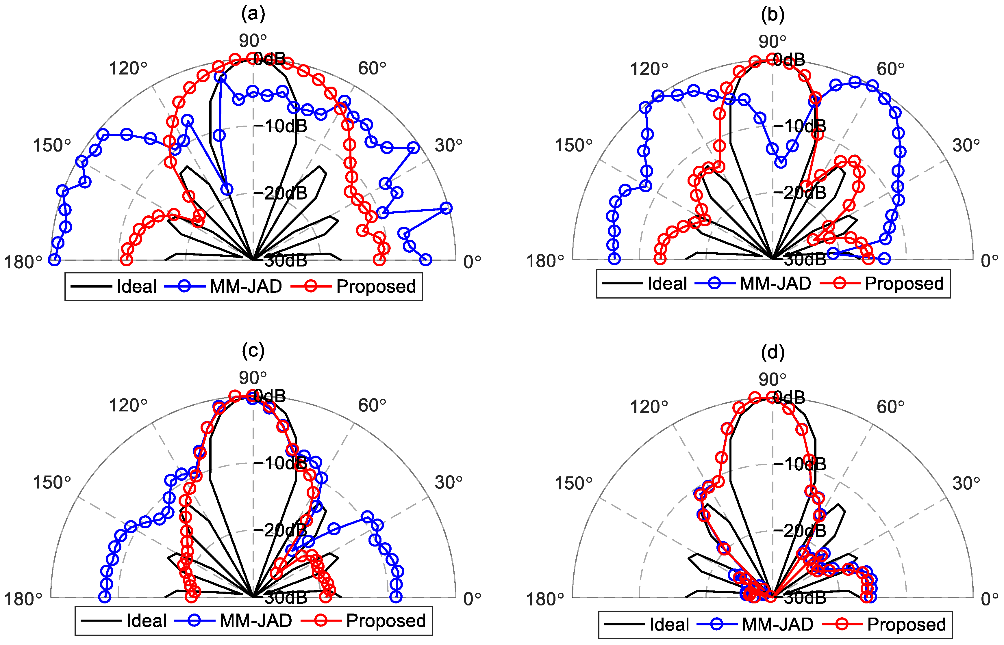
4.3.1. Comparison with MM-JAD (the Method in [29])

Compared to the MM-JAD method, the proposed method improves the robustness of the solution by adding a regularization parameter. Figure 5. shows that the regularization parameter mainly affects the performance of the beamformers below 1 kHz. To better evaluate the differences between the proposed method and the MM-JAD method at low frequencies, Figure 6 presents comparisons between the synthesized beampattern by the MM-JAD method, the proposed method, and the ideal beampattern at frequencies of 250 Hz, 500 Hz, 750 Hz, and 1 kHz. The regularization parameter is set to 0.01. As can be seen at 250 Hz and 500 Hz, compared with the proposed method, the beampattern synthesized by MM-JAD is closer to the ideal beampattern. The beamformer designed by the proposed method cannot generate the target sixth-order broadside beampattern but forms a second-order and a fourth-order broadside beampattern, respectively. At 750 Hz, the proposed method can form a sixth-order beampattern, and the match with the sidelobe of the ideal beampattern is not as good as the MM-JAD. At 1 kHz, the beampatterns produced by both MM-JAD and the proposed method are similar, with slight difference from the ideal beampattern.
The performance comparison between the beamformers synthesized by MM-JAD and those synthesized by the proposed method is listed in Table 1. As seen, at 250 Hz, the proposed method obtained a higher WNG than that of the MM-JAD method by sacrificing the performance of DI. At 500 Hz, the proposed method improves the WNG by adding a regularization parameter. Meanwhile, the DI of the proposed method is comparable to that of the MM-JAD method. At 750 Hz, the WNG of the proposed method has been further improved and the DI is also higher than that of the MM-JAD method. At 1 kHz, the WNG and the DI values of the two methods are similar, indicating the MM-JAD method is robust enough at high frequencies, and the improvement due to adding the regularization parameter is not significant. Hence, it can be found that, compared to the MM-JAD method, the proposed method balances system robustness and directivity by adding a regularization parameter to trade-off between the WNG and DI at low frequencies.

4.3.2. Performance Comparison between MM-JAD and the Proposed Method with the Perturbations Added to the Spatial Responses of the Loudspeakers

To demonstrate the proposed method is more robust than the MM-JAD method at low frequencies, the performance of the two methods are evaluated under uncertainties in the frequency response of the loudspeakers, for which the error has a multiplicative form with uniform distribution between −3 and +3 dB in magnitude and uniform distribution between −10° and +10° in phase. The performance averages over 5000 Monte Carlo trails describe the performance of the system with robustness.
Figure 7 shows comparisons of the desired beampattern and the averaged simulated beampatterns with the two methods. It can be seen from Figure 7a that, at 250 Hz, the beampattern synthesized by the MM-JAD method deviates significantly from the ideal beampattern and we cannot discern any directionality of the beamformer from the radiated beampattern. Although the beampattern radiated by the proposed method does not form the target sixth-order beampattern, the fact that the main lobe is 10 dB higher than the sidelobes indicates that the beamformer already exhibits directionality. At 500 Hz, the MM-JAD method still lacks directionality, but the main lobe of the beampattern radiated by the proposed method already resembles that of the ideal beampattern. At 750 Hz, the main lobe of the MM-JAD method is approaching that of the desired beampattern, but the sidelobes still deviate significantly. Meanwhile, the main lobe and sidelobes of the proposed method are both approaching that of the ideal beampattern. At 1 kHz, the two methods are both robust enough to approximate the target beampattern when the errors occur. The above indicates that, although Figure 6 shows that the MM-JAD method approaches the desired beampattern more closely than the proposed method below 750 Hz when disregarding element imperfections, the directivity of the MM-JAD method significantly decreases once there are element inconsistencies. Therefore, in practical applications, the proposed method will have an advantage over the MM-JAD method.
Table 2 lists comparisons with the averaged WNG and DI performance of the two methods. At 250 and 500 Hz, the WNG of the MM-JAD method below −15 dB and the corresponding DI value below 0 dB indicate that the energy radiated by the line array to the broadside is lower than the averaged energy radiated by the array to the front half-plane. At 750 Hz, as the WNG of the MM-JAD method is above 0 dB, the DI reaches 7.3. At 1 kHz, due to the WNGs, the two methods are all above 12 dB, and their DI values are also relatively close. Comparing Table 1 and Table 2, it can be observed that with the perturbations in the spatial responses of the loudspeakers, the WNG and DI of the proposed method remain almost consistent. This also indicates that the beamformer with Tikhonov regularization can mitigate the impact of transfer function errors on the beamformer.

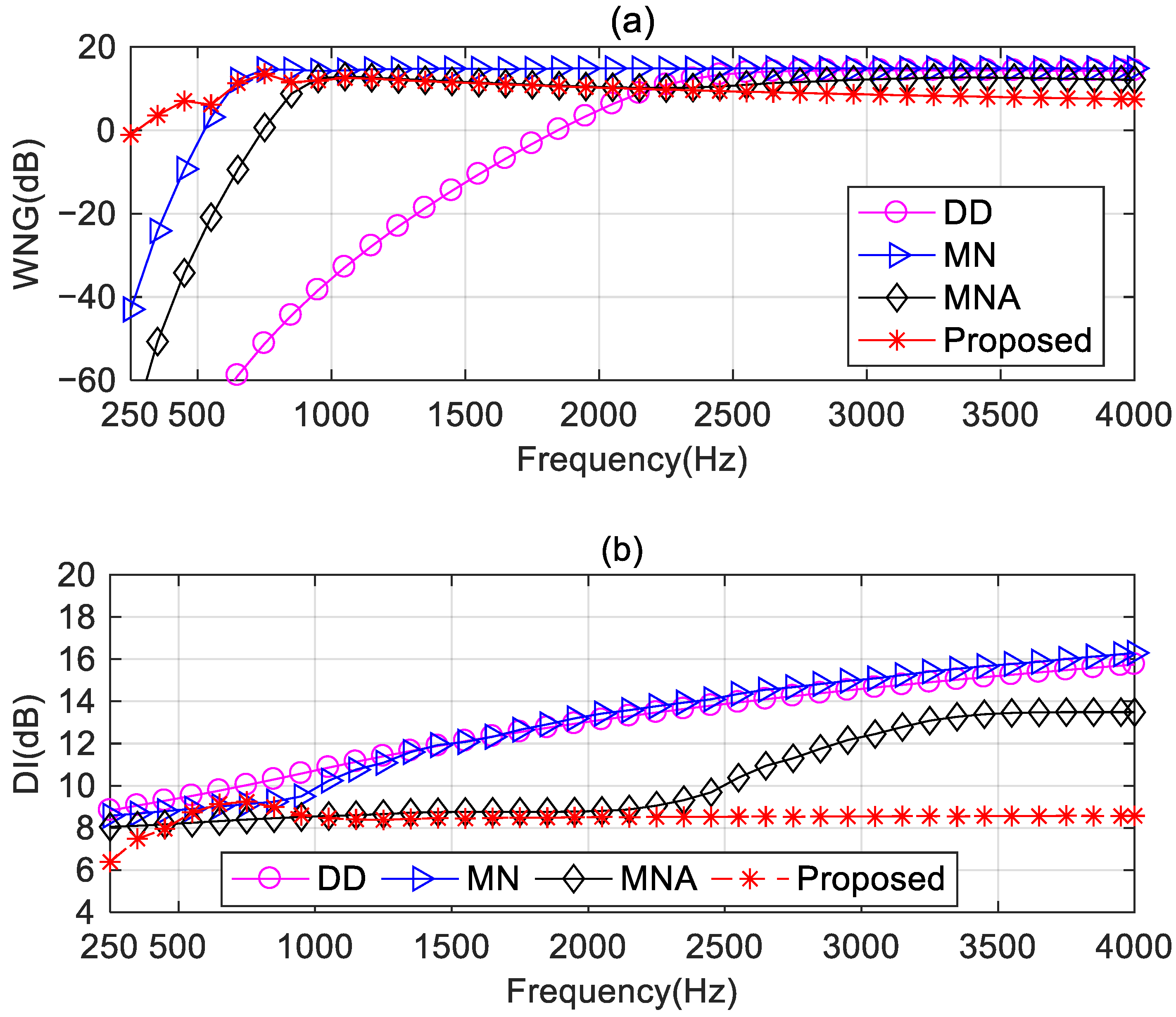
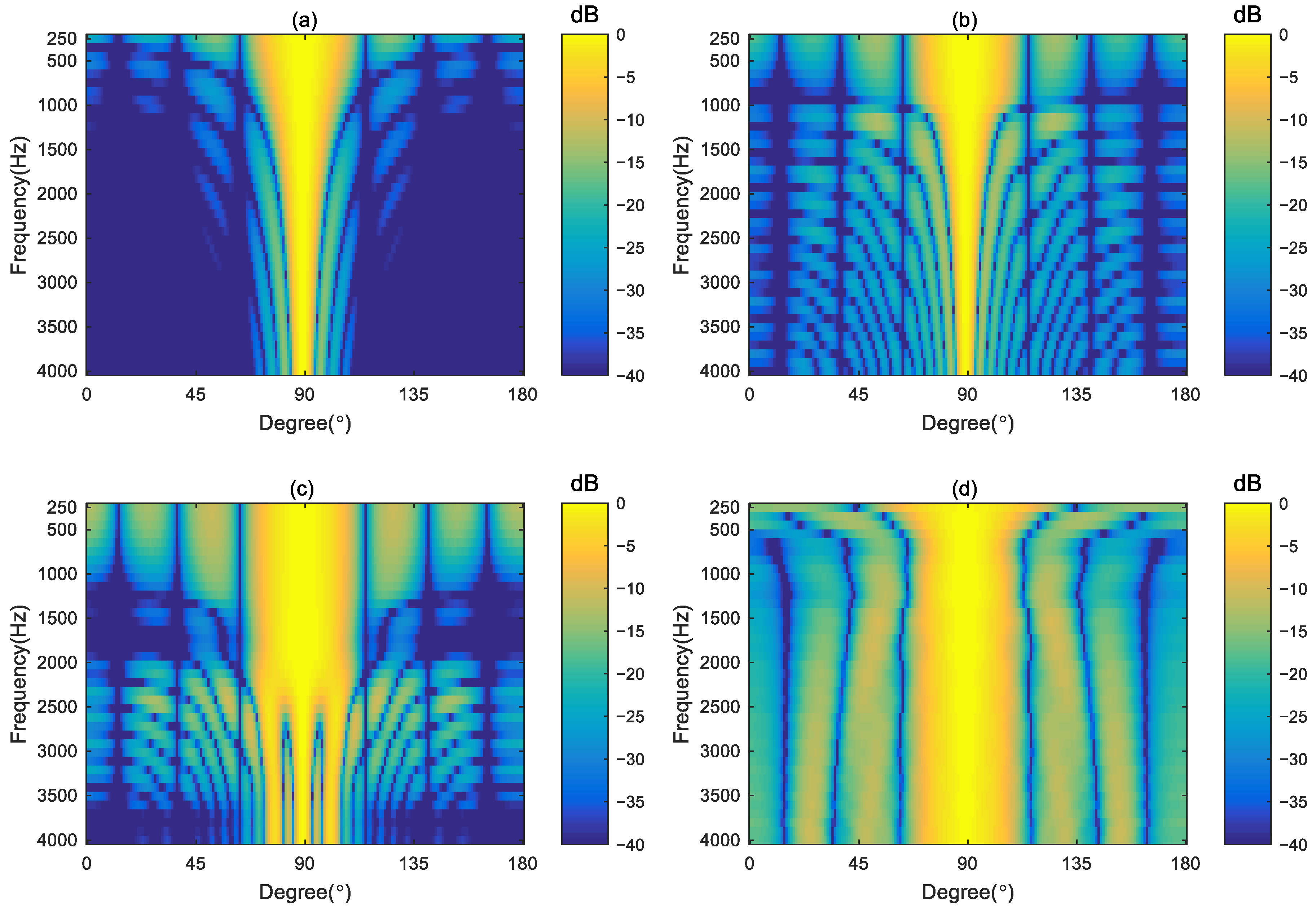
4.3.3. Comparison with the Other Differential Beamforming Methods

In this section, to demonstrate the performance and advantages of the proposed method, we compare the performance of the proposed method with three other existing broadside differential beamforming methods: (i) the DD method [7], which combines the differential and delay-and-sum patterns, (ii) the MN method [26], which utilizes the null position for the target beampattern to design the beamformer, and (iii) the MNA method [26], which uses the null position and the angle corresponding half-power bandwidth for the target beampattern to design the beamformer. In the simulations, the regularization parameter of the proposed method is set to 0.01 across the whole evaluated frequencies.
Figure 8 shows the WNG and DI of the proposed method compared with the methods DD, MN, and MNA. In Figure 8a, the DD method has the lowest WNG among the four methods below 2 kHz, indicating the worst anti-perturbation ability at low frequencies. The MN method has the maximum WNG above 1 kHz. The proposed method has the highest WNG below 500 Hz and has the same WNG as the MNA method in the frequency range of 1–2.5 kHz. Although the WNG of the proposed method is the lowest above 2.5 kHz, the value is still greater than 5 dB, which is considered as a proper level of robustness in practical applications. Figure 8b shows the DI of the DD and MN methods increases with frequency. The DI of the MNA method maintains almost the same below 2 kHz but increases with frequency above 2 kHz. The DI of the proposed method can maintain a constant above 1 kHz. Below 1 kHz, due to the trade-off between the WNG and DI, the DI of the proposed method exhibits slight fluctuations.
The wideband beampattern can intuitively illustrate the broadband frequency-invariant characteristics of the beamformer. We present the synthesized beampattern of these four methods in Figure 9. The main lobes of the DD and MN methods become narrower as the frequency increases. Below 2 kHz, the main lobe of the MNA method remained almost the same. However, grating lobes appear above 2 kHz. In contrast, the proposed method maintained the frequency-invariant pattern in the frequency range of 750–4k Hz. Although the proposed method cannot hold the frequency-invariant beampattern below 750 Hz, the beampattern shown in Figure 9d reflects the actual beampattern radiated by the line array due to the increased WNG.

5. Experiments

5.1. Experimental Setup

To evaluate the practical performance of the proposed method, a line array of 31 loudspeakers (HiVi B1S) with spacing of 0.038 m, shown in Figure 10a, has been built. The experimental setup is shown in Figure 10b. The array was installed in an anechoic chamber and placed on top of a turntable. An omni-directional microphone (BSWA MPA201) was placed at 3 m from the geometrical center of the array. Both the microphone and the line array were placed at a height of 2 m from the floor.
The transfer functions between loudspeakers in the array and the microphone have been measured. The speaker is excited by linear swept sine signal in the frequency range of 250–4k Hz with resolution of 5 Hz, and an AP2720 audio analyzer is used to measure the transfer functions from the loudspeaker to the microphone position. The transfer functions measured at every 5° from 0° to 180° by using the turntable have been undertaken to calculate the measured beampattern by different beamforming methods.

5.2. Results and Discussion

In this section, we will present the comparative results of the experiments to demonstrate the advantages of the proposed method over other existing beamforming methods.

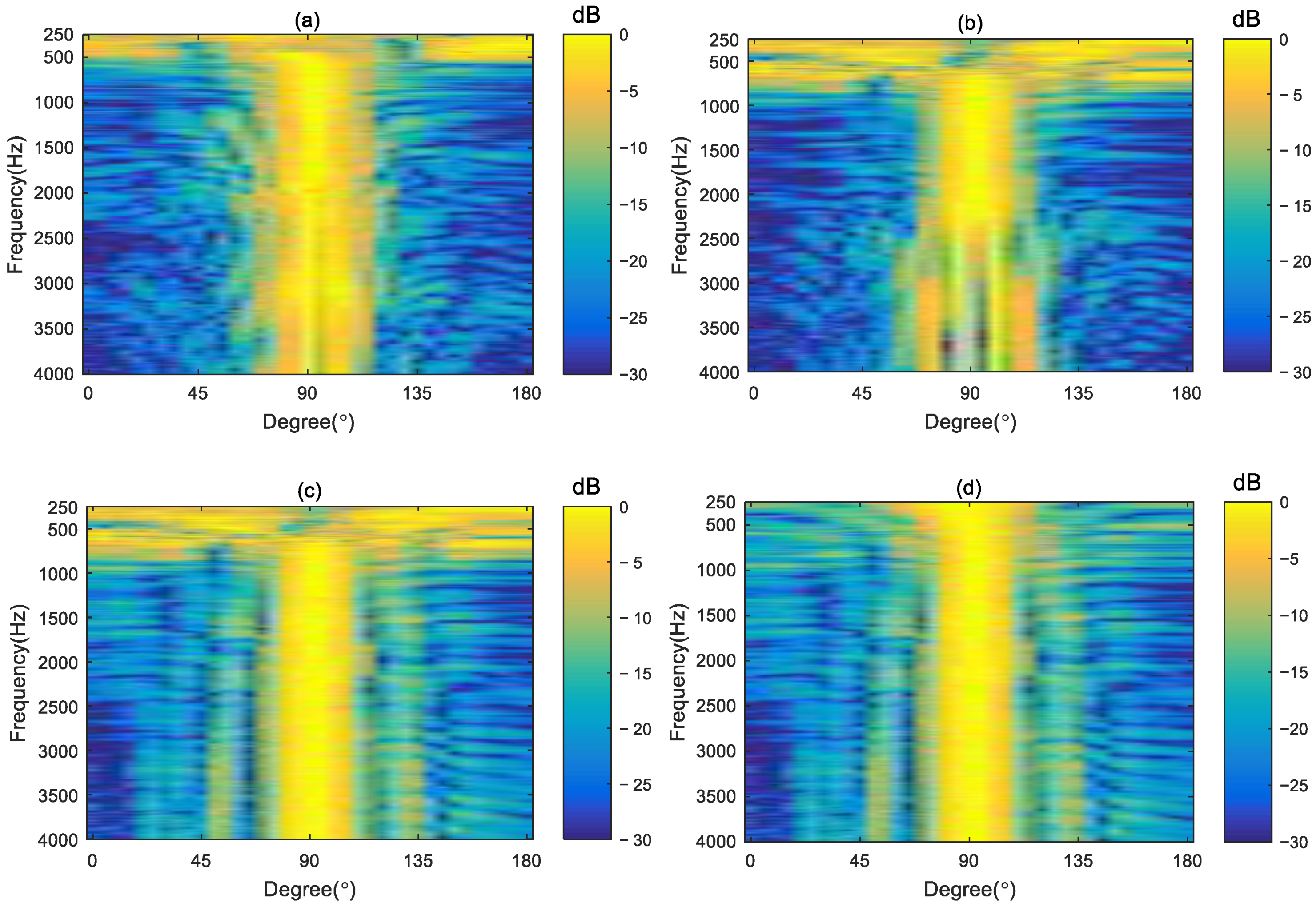
5.2.1. Comparison with Other Broadside Differential Beamforming Methods

The main objective of the proposed beamformer is to design a broadside differential beampattern over a wide range of frequencies. Figure 11 presents the measured beampatterns by four different methods: MN, MNA, MM-JAD, and the proposed method with a regularization parameter of 0.01 within the frequency range of 250–4k Hz. Figure 11a shows the MN method cannot generate an effective beampattern under 500 Hz. The main lobes kept very well in the frequency range of 500–1k Hz and became narrower as the frequency increases above 1k Hz. From Figure 11b, the MNA method also fails to produce an effective beampattern at low frequencies. In the frequency range of 1–2.2 kHz, the main lobe of the beampattern can remain constant. However, grating lobes appear above 2.2 kHz. By comparing Figure 11c,d, it can be seen that above 1 kHz, the beampattern generated by both the MM-JAD method and the proposed method can maintain a constant beam width. However, below 1 kHz, the beampattern formed by the proposed method is superior to that generated by the MM-JAD method. Comparing the measured beampatterns in Figure 11d with the simulation results shown in Figure 11d, the experimental results are consistent with the simulation results, which demonstrates that the broadside frequency-invariant beampattern can be synthesized by the proposed method in a broad band of frequencies.

5.2.2. Comparison with the Method in Ref. [29] (MM-JAD) at Low Frequencies

To better observe the superiority of our proposed method compared to the method in Ref. [29] at low frequencies, we compare the measured beampattern designed by the MM-JAD method and the proposed method with the ideal beampattern at four different frequencies: 250 Hz, 500 Hz, 750 Hz, and 1k Hz. Figure 12 gives the comparison results. From Figure 12a,b, the maximum value of the beampattern of the MM-JAD method is not in the broadside direction, indicating that the MM-JAD method cannot generate an effective beampattern below 500 Hz. Meanwhile, although the beampattern of the proposed method does not approximate the ideal beampattern as expected, it can produce an effective beampattern in the broadside direction. The experiment results are consistent with the simulation results shown in Figure 7a,b. From Figure 12c, it can be seen that at 750 Hz, the main lobe of the MM-JAD method is close to that of the ideal beampattern, but there is still a significant deviation in the sidelobes. Figure 12d shows that at 1 kHz, despite array imperfections and measurement errors causing the sidelobes and null positions of the two methods differ from the ideal beampattern, the beampatterns of the MM-JAD and the proposed methods are identical, validating the conclusion obtained during the simulation: when the WNG is large, the proposed method yields the same results as the MM-JAD method.

5.2.3. Comparison with Benchmark Beamforming Methods

To further illustrate the superiority of the proposed method in generating broadband frequency-invariant beampatterns, we compared the proposed method with traditional beamforming methods. We selected two classical beamformers as our benchmark methods, namely the Delay and Sum (DS) method, which is derived by maximizing the WNG [7], and the Minimum Variance Distortionless Response (MVDR) method, which aims to minimize the output power of the array while maintaining a distortionless response in the desired direction [33]. The MVDR method requires a regularization parameter during the solving process. We set the regularization parameter to 0.01, which is consistent with the regularization parameter added in the proposed method. Figure 13 gives the measured broadband radiation patterns of the benchmark methods. Comparing Figure 13 with Figure 12d, it can be found that the main lobe of the beampattern generated by the DAS and MVDR methods becomes narrower as the frequency increases. Meanwhile, the main lobe of the beampattern synthesized by the proposed method remains constant throughout the entire evaluation frequency range, even at high frequencies.

6. Conclusions

In this paper, a robust broadside frequency-invariant beamforming method is proposed for a differential loudspeaker line array. We present a method to calculate the ideal broadside beampattern combining various criteria, namely, null information, maximizing the directivity factor, and achieving the beampattern with equal sidelobes. We derive the modal domain target beampattern of a given ideal broadside differential beampattern. We propose a robust modal matching method with Tikhonov regularization to design the broadside beamformer in the modal domain. Simulations and experimental results show that the proposed method outperforms the null-constrained and MM-JAD methods, achieving frequency-invariant broadside beamforming over the range of 250 Hz–4 kHz. It is worth noting that the above analysis and results are obtained under free-field conditions. The proposed method was only validated at a distance of 3 m in an anechoic chamber. In a regular room, the directional performance of the proposed method may degrade due to the influence of room reflections. Future work will verify the proposed method in more complex and real-world environments.

Author Contributions

Conceptualization, Y.Z.; methodology, Y.Z.; software, Y.Z.; validation, Y.Z. and H.W.; formal analysis, Y.Z. and Q.Z.; investigation, Y.Z.; resources, Y.Z.; data curation, Y.Z. and H.W.; writing—original draft preparation, Y.Z.; writing—review and editing, Q.Z.; visualization, Y.Z.; supervision, Y.Z.; project administration, Y.Z. and H.W.; funding acquisition, Y.Z. and H.W. All authors have read and agreed to the published version of the manuscript.

Funding

This research was funded by the Natural Science Research Project of Anhui Educational Committee (Grant No. 2023AH050422), Open Project of Anhui Digital Intelligent Engineering Research Center for Agricultural Products Quality Safety under the Peak Cultivation Discipline of Electronic Information (Grant No. APDI202304), and Open Project of Anhui Province Photovoltaic Industry Common Technology Research Center under the Peak Cultivation Discipline of Electronic Information (Grant No. AHPV202303).

Institutional Review Board Statement

Not applicable.

Informed Consent Statement

Not applicable.

Data Availability Statement

Data are available upon request.

Conflicts of Interest

The authors declare no conflicts of interest.

References

  1. Perla, J.; Bulla, W. A qualitative investigation of soundbar theory. In Proceedings of the Audio Engineering Society Convention 147, New York, NY, USA, 16–19 October 2019. [Google Scholar]
  2. Pan, K.; Huang, J.; Cheng, J.; Shen, Y. Loudspeaker array beamforming for sound projection in a half-space with an impedance boundary. J. Acoust. Soc. Am. 2023, 153, 1626–1636. [Google Scholar] [CrossRef]
  3. Brunskog, J.; Heuchel, F.M.; Nozal, D.C.; Song, M.; Agerkvist, F.T.; Fernandez-Grande, E.; Gallo, E. Full scale outdoor concert adaptive sound field control. In Proceedings of the 23rd International Congress on Acoustics(ICA), Aachen, Germany, 9–13 September 2019; pp. 1170–1177. [Google Scholar]
  4. Start, E. Loudspeaker Matrix Arrays: Challenging the way we create and control sound. In Proceedings of the Audio Engineering Society Conference: AES 2024 International Acoustics & Sound Reinforcement Conference, Le Mans, France, 23–26 January 2024. [Google Scholar]
  5. Zhu, Q.; Qiu, X.; Coleman, P.; Burnett, I. A comparison between two modal domain methods for personal audio reproduction. J. Acoust. Soc. Am 2020, 147, 161–173. [Google Scholar] [CrossRef] [PubMed]
  6. Huang, Y.; Zhao, S.; Lu, J. Acoustic contrast control with a sound intensity constraint for personal sound systems. J. Acoust. Soc. Am. 2024, 155, 879–890. [Google Scholar] [CrossRef] [PubMed]
  7. Kim, Y.-H.; Choi, J.-W. Sound Visualization and Manipulation; John Wiley & Sons: Hoboken, NJ, USA, 2013. [Google Scholar]
  8. Chen, J.; Benesty, J.; Pan, C. On the design and implementation of linear differential microphone arrays. J. Acoust. Soc. Am 2014, 136, 3097–3113. [Google Scholar] [CrossRef] [PubMed]
  9. Zhao, L.; Benesty, J.; Chen, J. Design of robust differential microphone arrays with the Jacobi–Anger expansion. Appl. Acoust. 2016, 110, 194–206. [Google Scholar] [CrossRef]
  10. Jin, J.; Huang, G.; Wang, X.; Chen, J.; Benesty, J.; Cohen, I. Steering Study of Linear Differential Microphone Arrays. IEEE/ACM Trans. Audio Speech Lang. Process. 2021, 29, 158–170. [Google Scholar] [CrossRef]
  11. Elko, G.W. Superdirectional Microphone Arrays. In Acoustic Signal Processing for Telecommunication; Springer: Berlin, Germany, 2000. [Google Scholar]
  12. Luo, X.; Jin, J.; Huang, G.; Chen, J.; Benesty, J. Design of Steerable Linear Differential Microphone Arrays With Omnidirectional and Bidirectional Sensors. IEEE Signal Process. Lett. 2023, 30, 463–467. [Google Scholar] [CrossRef]
  13. Pan, C.; Benesty, J.; Chen, J. Design of robust differential microphone arrays with orthogonal polynomials. J. Acoust. Soc. Am. 2015, 138, 1079–1089. [Google Scholar] [CrossRef] [PubMed]
  14. Yu, G. Eigenbeam-space transformation based steerable differential beamforming for linear arrays. Signal Process. 2023, 212, 109171. [Google Scholar] [CrossRef]
  15. Huang, G.; Chen, J.; Benesty, J. Insights Into Frequency-Invariant Beamforming With Concentric Circular Microphone Arrays. IEEE/ACM Trans. Audio Speech Lang. Proc 2018, 26, 2305–2318. [Google Scholar] [CrossRef]
  16. Wang, J.; Yang, F.; Li, J.; Sun, H.; Yang, J. Mode matching-based beamforming with frequency-wise truncation order for concentric circular differential microphone arrays. J. Acoust. Soc. Am. 2023, 154, 3931–3940. [Google Scholar] [CrossRef] [PubMed]
  17. Luo, X.; Jin, J.; Huang, G.; Zhao, Y.; Chen, J.; Benesty, J. On the Design of Planar Differential Microphone Arrays with Specified Beamwidth or Sidelobe Level. In Proceedings of the ICASSP 2024—2024 IEEE International Conference on Acoustics, Speech and Signal Processing (ICASSP), Seoul, Republic of Korea, 14–19 April 2024; pp. 8536–8540. [Google Scholar]
  18. Wang, J.; Yang, F.; Yan, Z.; Yang, J. Design of frequency-invariant uniform concentric circular arrays with first-order directional microphones. Signal Process. 2024, 217, 109330. [Google Scholar] [CrossRef]
  19. Albertini, D.; Bernardini, A.; Borra, F.; Antonacci, F.; Sarti, A. Two-Stage Beamforming With Arbitrary Planar Arrays of Differential Microphone Array Units. IEEE/ACM Trans. Audio Speech Lang. Process. 2023, 31, 590–602. [Google Scholar] [CrossRef]
  20. Itzhak, G.; Cohen, I. Differential constant-beamwidth beamforming with cube arrays. Speech Commun. 2023, 149, 98–107. [Google Scholar] [CrossRef]
  21. Zhao, X.; Huang, G.; Chen, J.; Benesty, J. Design of 2D and 3D Differential Microphone Arrays With a Multistage Framework. IEEE/ACM Trans. Audio Speech Lang. Process. 2023, 31, 2016–2031. [Google Scholar] [CrossRef]
  22. Zhao, X.; Luo, X.; Huang, G.; Chen, J.; Benesty, J. Differential Beamforming with Null Constraints for Spherical Microphone Arrays. In Proceedings of the ICASSP 2024—2024 IEEE International Conference on Acoustics, Speech and Signal Processing (ICASSP), Seoul, Republic of Korea, 14–19 April 2024; pp. 776–780. [Google Scholar]
  23. Wang, X.; Benesty, J.; Chen, J.; Huang, G.; Cohen, I. Beamforming with Cube Microphone Arrays Via Kronecker Product Decompositions. IEEE/ACM Trans. Audio Speech Lang. Process. 2021, 29, 1774–1784. [Google Scholar] [CrossRef]
  24. Choi, J.-W.; Kim, Y.; Ko, S.; Kim, J. A differential approach for the implementation of superdirective loudspeaker array. In Proceedings of the Audio Engineering Society Convention 128, London, UK, 22–25 May 2010. [Google Scholar]
  25. Choi, J.W. Generation of a Near-field Sound Zone Using Broadside Differential Array. In Proceedings of the 2021 Immersive and 3D Audio: From Architecture to Automotive (I3DA), Bologna, Italy, 8–10 September 2021. [Google Scholar]
  26. Wang, J.; Zhang, W.; Pan, C.; Chen, J.; Benesty, J. On the design of differential loudspeaker arrays with broadside radiation patterns. JASA Express Lett. 2021, 1, 084804. [Google Scholar] [CrossRef] [PubMed]
  27. Zhang, Y.; Mao, J.; Cai, Y.; Ye, C. Sound reproduction with a circular loudspeaker array using differential beamforming method. In Proceedings of the 2022 Asia-Pacific Signal and Information Processing Association Annual Summit and Conference (APSIPA ASC), Chiang Mai, Thailand, 7–10 November 2022; pp. 143–148. [Google Scholar]
  28. Miotello, F.; Bernardini, A.; Albertini, D.; Antonacci, F.; Sarti, A. Steerable First-Order Differential Loudspeaker Arrays with Monopole and Dipole Elements. In Proceedings of the Convention of the European Acoustics Association, Forum Acusticum, Turin, Italy, 11–15 September 2023; pp. 11–15. [Google Scholar]
  29. Zhang, Y.; Mao, J.; Cai, Y.; Ye, C.; Zhu, Q. Broadband frequency-invariant broadside beamforming with a differential loudspeaker array. In Proceedings of the 2023 31st European Signal Processing Conference (EUSIPCO), Helsinki, Finland, 4–8 September 2023; pp. 1728–1732. [Google Scholar]
  30. Pan, C.; Chen, J.; Benesty, J.; Shi, G. On the Design of Target Beampatterns for Differential Microphone Arrays. IEEE/ACM Trans. Audio Speech Lang. Process. 2019, 27, 1295–1307. [Google Scholar] [CrossRef]
  31. Macdonald, I.G. Symmetric functions and Hall polynomials; Oxford University Press: Oxford, UK, 1998. [Google Scholar]
  32. Zhao, X.; Huang, G.; Chen, J.; Benesty, J. An improved solution to the frequency-invariant beamforming with concentric circular microphone arrays. In Proceedings of the ICASSP 2020-2020 IEEE International Conference on Acoustics, Speech and Signal Processing (ICASSP), Barcelona, Spain, 4–8 May 2020; pp. 556–560. [Google Scholar]
  33. Bitzer, J.; Simmer, K.U. Superdirective microphone arrays. In Microphone Arrays: Signal Processing Techniques and Applications; Springer: Berlin/Heidelberg, Germany, 2001; pp. 19–38. [Google Scholar]
Figure 1. Broadside beamforming with a differential loudspeaker line array.
Applsci 14 06383 g001
Figure 2. The target broadside radiation pattern was designed by multiple criteria. (a) The second-order broadside beampattern with nulls at 15° and 165°. (b) The fourth-order target beampattern with nulls at 15°, 45°, 135°, and 165°. (c) The second-order target beampattern with maximum directivity factor. (d) The fourth-order target beampattern with maximum directivity factor. (e) The fourth-order ideal beampattern with equal sidelobe level, where S is set to 10 dB. (f) The fourth-order ideal beampattern with equal sidelobe levels, where S is set to 20 dB.
Applsci 14 06383 g002aApplsci 14 06383 g002b
Figure 3. Synthesized broadside beampatterns for a line array of 31 loudspeakers. (a) Second-order, (b) fourth-order, (c) sixth-order, (d) eighth-order.
Applsci 14 06383 g003aApplsci 14 06383 g003b
Figure 4. The performance of the different-order synthesized beamformers: (a) WNG and (b) DI.
Applsci 14 06383 g004
Figure 5. Performance comparison of the sixth-order synthesized beamformer with different regularization parameters: (a) WNG and (b) DI.
Applsci 14 06383 g005
Figure 6. The simulated and ideal beampatterns of the sixth-order broadside differential beamformers synthesized by MM-JAD and the proposed method at different frequencies. (a) 250 Hz, (b) 500 Hz, (c) 750 Hz, (d) 1 kHz.
Applsci 14 06383 g006
Figure 7. The averaged simulated and ideal beampatterns of the sixth-order broadside differential beamformers synthesized by MM-JAD and the proposed method with the perturbation added to the frequency response of the loudspeakers at different frequencies. (a) 250 Hz, (b) 500 Hz, (c) 750 Hz, and (d) 1 kHz.
Applsci 14 06383 g007aApplsci 14 06383 g007b
Figure 8. Performance of generating the sixth-order broadside differential beampattern regarding (a) WNG and (b) DI.
Applsci 14 06383 g008
Figure 9. Synthesized beampatterns of (a) DD, (b) MN, (c) MNA, and (d) proposed method.
Applsci 14 06383 g009
Figure 10. Photo of the line array with 31 loudspeakers and experimental setup of the measurement: (a) the line array and (b) the experimental setup.
Applsci 14 06383 g010
Figure 11. The measured radiation patterns of different methods for the design of a sixth-order broadside differential pattern: (a) Ref. [26] A, (b) Ref. [26] B, (c) Ref. [29], (d) proposed.
Applsci 14 06383 g011
Figure 12. Comparisons of the measured beampattern generated by MM-JAD and the proposed method with the ideal beampattern at (a) 250 Hz, (b) 500 Hz, (c) 750 Hz, (d) 1 kHz.
Applsci 14 06383 g012
Figure 13. The measured radiation patterns of the benchmark methods (a) DAS and (b) MVDR.
Applsci 14 06383 g013
Table 1. The WNG and DI performance (dB) of -MM-JAD and the proposed method at 250 Hz, 500 Hz, 750 Hz, and 1 kHz.
Freq (Hz)WNG (dB)DI (dB)
-MM-JADProposed-MM-JADProposed
250−61.8−1.18.56.4
500−245.88.58.3
750−0.113.68.49.2
100012.112.48.48.5
Table 2. The averaged WNG and DI performance (dB) of MM-JAD and the proposed method with the perturbation added to the frequency response of the loudspeakers at 250 Hz, 500 Hz, 750 Hz, and 1 kHz.
Freq (Hz)WNG (dB)DI (dB)
-MM-JADProposed-MM-JADProposed
250−15.6−1.1−1.85.6
500−15.45.8−2.18.1
7500.314.07.39.2
100012.612.88.38.4
Disclaimer/Publisher’s Note: The statements, opinions and data contained in all publications are solely those of the individual author(s) and contributor(s) and not of MDPI and/or the editor(s). MDPI and/or the editor(s) disclaim responsibility for any injury to people or property resulting from any ideas, methods, instructions or products referred to in the content.

