Article

Research on Bifurcated Origami Hydraulic Dampers for Real Road Vibration Loads

1
Department of Mechanical Engineering, Graduate School, Saitama Institute of Technology, Saitama 369-0293, Japan
2
National Institute of Technology, Toyama College, Toyama 939-8630, Japan
*
Author to whom correspondence should be addressed.
Appl. Sci. 2024, 14(14), 6374; https://doi.org/10.3390/app14146374
Submission received: 14 June 2024 / Revised: 12 July 2024 / Accepted: 19 July 2024 / Published: 22 July 2024
(This article belongs to the Special Issue Vibration Problems in Engineering Science)

Abstract

:
Cylindrical hydraulic dampers are commonly utilized to mitigate vibrations in machinery and structural applications. These devices generally feature a single linear stroke and are often linked to rotary joints to handle complex loading conditions. However, their installation in confined spaces, such as vehicle suspensions, poses considerable difficulties. In this research, we introduce an innovative bifurcated origami hydraulic damper with nonlinear damping capabilities. Initially, we formulated the collapsible conditional equations essential for the design of the bifurcated origami hydraulic dampers. We then examined the fluid dynamics within the damper and its flow channels, determining that the damping force is proportional to the square of the velocity. Furthermore, we developed motion equations based on the derived damping force and suggested vibration analysis methods using the Runge–Kutta approach. For the mass-spring vibration system, we created an experimental setup with the bifurcated origami hydraulic damper and performed vibration tests using noise signals recorded from a vehicle traveling on a gravel road, thus validating its damping performance and efficacy. Additional tests, which varied the orifice size at the end of the origami structure, as well as the type and temperature of the internal fluid, showed that the orifice size had a more pronounced effect on damping efficiency than the fluid type and temperature. This confirmed the vibration-damping effectiveness of the bifurcated origami hydraulic damper.

1. Introduction

Hydraulic dampers are damping elements that convert the kinetic energy of moving parts into thermal energy. This avoids hard impacts or excessive vibration amplitudes. They have been widely utilized as energy-absorbing components in vibration-damping systems and devices. Numerous studies have investigated their performance and advancements for various applications [1,2,3,4,5].
These dampers are highly effective at mitigating road vibrations and impact forces from obstacles, thereby enhancing passenger comfort [6,7,8,9,10]. Furthermore, magneto-rheological dampers, which enhance traditional hydraulic dampers by modifying their mechanical properties through an external magnetic field, have been developed [11,12,13]. In the construction industry, the installation of semi-active hydraulic dampers along the diagonals of rectangular frames in buildings and bridges has been shown to significantly reduce seismic damage [14,15,16].
However, most available hydraulic dampers are of the metal cylinder type, which can only move in one direction. Their actual retractable length is limited by their total axle length and the available mounting space, making them difficult to use. For lightweighting, new lightweight, nonmetallic hydraulic dampers must be developed to replace metal cylindrical dampers. Origami structures developed according to the requirements of the mechanical properties of the structure, which typically involve intricate folding patterns that transform a flat sheet of paper into complex and surprisingly sturdy forms and have been studied in terms of basic aspects such as geometry [17,18,19,20,21,22]. Tubular origami structures, which can freely collapse in the axial direction, can be used as alternatives to conventional metallic dampers. The geometries of these collapsible tubular origami structures and their deformation characteristics when subjected to external forces have been investigated [23,24]. Lightweight and flexible robotic arms are required in the field of automation research. Currently, research is being conducted on the application of collapsible tubular origami structures to robotic arms, hands, and grippers by flexibly utilizing their properties [25,26,27].
In addition, hydraulic dampers have been investigated by injecting hydraulic oil into a unidirectionally moving origami tube and adjusting the outlet size [28]. Moreover, considering the complex working conditions in two dimensions, an origami hydraulic oil damper that is freely foldable, capable of coping with bending strokes, and suitable for complex vibration conditions, such as impacts, was used instead of metallic cylindrical hydraulic dampers. This type of damper has been studied previously [29].
This study is a promising topic for the development of a new type of bifurcated origami hydraulic dampers, which utilizes the free expansion and contraction characteristics of origami structures to address the problems caused by narrow installation spaces and the difficulty of directly mounting cylindrical hydraulic dampers in automobile suspension systems.
To address the limited installation space, we propose a new type of bifurcated origami hydraulic damper and fabricate an experimental unit made of thin-walled polypropylene material. We theoretically analyzed the damping effect of bifurcated origami hydraulic dampers and derived a formula for the damping force required for practical applications. We conceptualized and developed a vibration system consisting of a moving mass block, an elastic spring, a connecting hose, and bifurcated origami hydraulic dampers. We proposed nonlinear dynamical governing equations for the vibration system and established a numerical vibration analysis method using the Runge–Kutta method. For validation, we conducted vibration tests using random vibration wave data measured when the vehicle traveled on a real gravel road and compared the measured experimental values of response acceleration to the numerical analysis values for a comprehensive investigation. Furthermore, the effects of different orifice holes, hydraulic oil types, and temperatures on the vibration-damping effect were investigated.

2. Materials and Methods

As shown in Figure 1, a conventional hydraulic cylinder damper is primarily composed of a cylinder, a piston, and an orifice hole. When the piston moves relative to the cylinder under the action of an external force, hydraulic oil produces a damping force through the orifice hole that counters the relative motion.
In Figure 1a, Lall is the length of the hydraulic cylinder damper, and Lstroke is the length of the movable piston. In practice, the utilization rate of the hydraulic cylinder damper Lstroke/Lall is less than 0.5, which makes it difficult to apply in spaces where installation space is limited.
If a new hydraulic damper is developed to replace the cylinder by utilizing the collapsible function of the origami structure, as shown in Figure 1b, the utilization of the damper can be significantly increased, and it can be applied to compact spaces.
However, as shown in Figure 1a, stress concentrations may occur around the pin support point when a cylindrical hydraulic damper is used to absorb complex vibration loads. In addition, these stresses can significantly impact the wear of the seals of the cylindrical hydraulic damper. To address these concerns, a cylindrical origami structure can be used to flexibly adapt to three-dimensional loads when complex vibration loads are applied to an origami hydraulic damper, as shown in Figure 2.

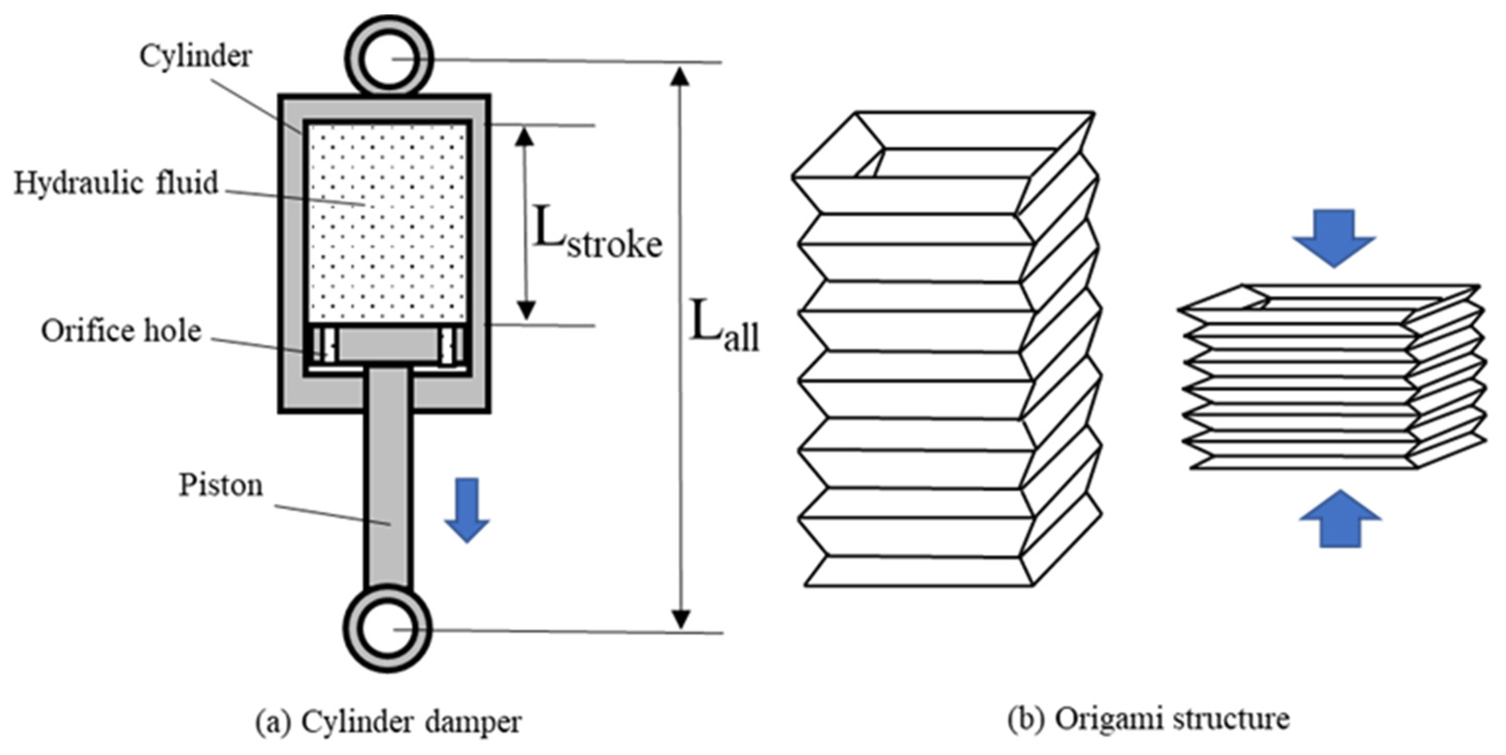
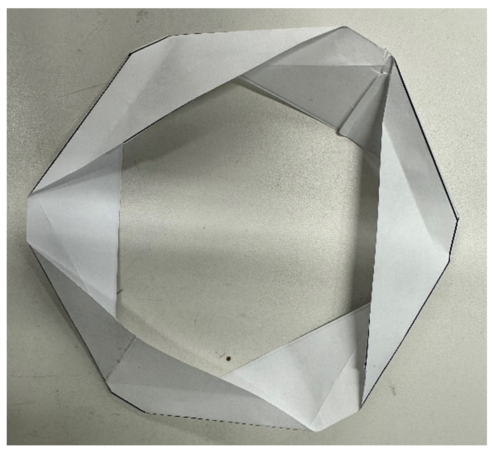
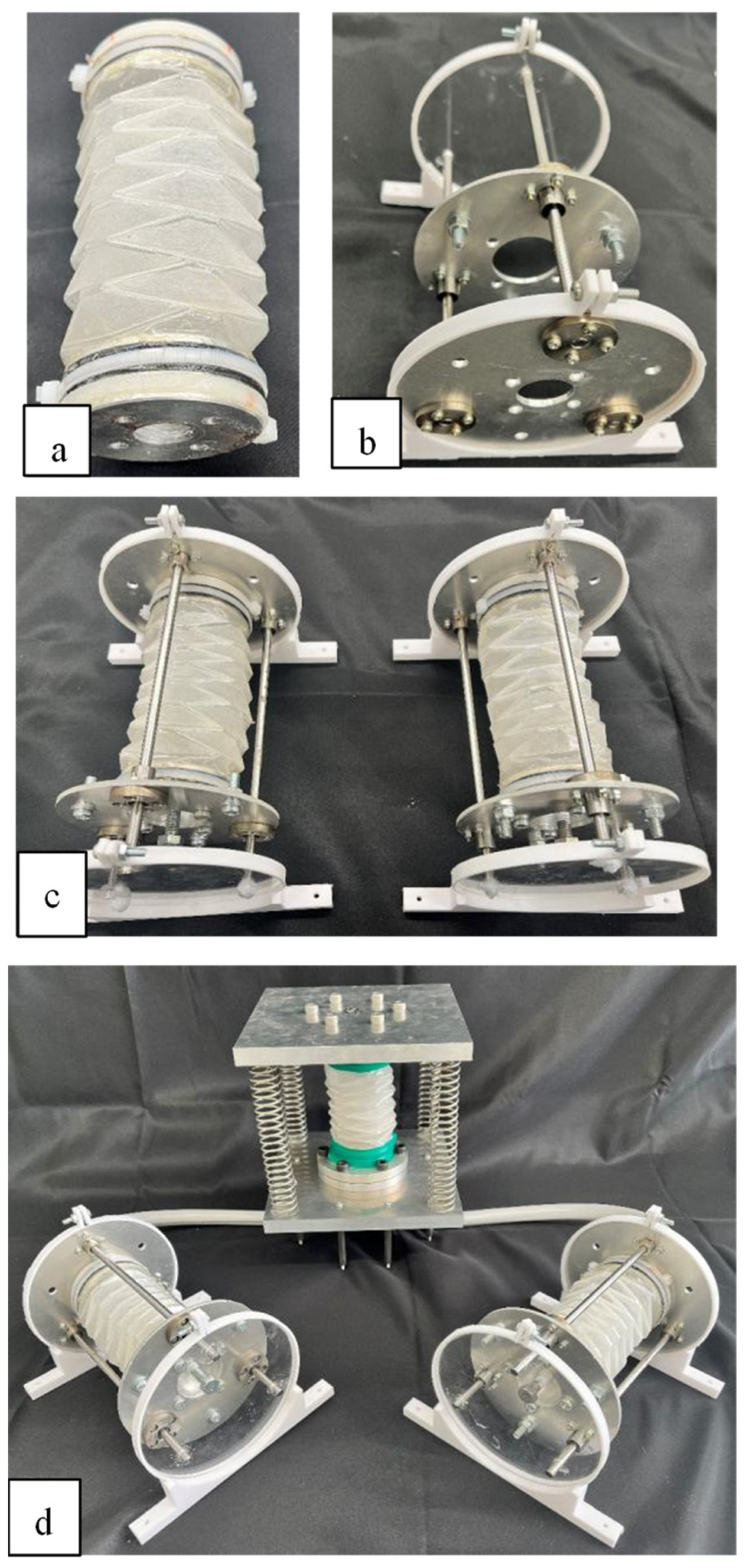
2.1. Bifurcated Origami Hydraulic Damper

To efficiently apply origami hydraulic dampers in compact spaces, we propose a bifurcated origami hydraulic damper, as shown in Figure 3. A tube connects the main and branch origami dampers, allowing hydraulic oil to flow back and forth between them.
In addition, an orifice hole is placed at the end of the bifurcated origami hydraulic damper. Accompanying the expansion and contraction changes in the cylindrical origami structure, the origami hydraulic damper induces a damping effect when the hydraulic oil passes through the orifice hole. The damping effect of the origami hydraulic damper can be adjusted by changing the size of the orifice holes.
In this study, we used polyethylene materials, which can be easily and quickly produced in the laboratory. The flat expansion view of the origami structure is shown in Figure 4. To achieve folding along the axial direction into a cylindrical origami structure with a closed circumference, it is essential to identify the inclination angles θ 1 , θ 2 , θ 3 , and θ 4 of the folds based on the number of segments n in the origami structure, as shown in Figure 4. The subsequent segments are arranged in an equal isosceles trapezoid array. Given that all the angles are the same, we only need to determine the appropriate size of one angle. The conditions for folding are expressed by the following equation.
θ 1 = θ 2 = θ 3 = θ 4 = π n
The one unit of origami structure folded is shown in Figure 5.
To verify the characteristics of the bifurcated origami hydraulic damper depicted in Figure 3, an experimental setup was developed and analyzed, as shown in Figure 6. This validation setup included the main origami damper, the bifurcated origami damper, an elastic spring, a mass block, a frame, and a fixed plate.
The validation experimental setup was structured as follows: First, in order to be easily and quickly produced, we used the transparent polyethylene cylinder sheet with a thickness of approximately 0.1 mm, as shown in Figure 6a, folded along the printing line to form a cylindrical origami structure. Moreover, the manufacturing process of the bifurcated origami hydraulic damper is the same as that in reference [28]. A trapezoidal acrylic sheet was attached to the side of the origami structure with an adhesive to further increase its rigidity. The finished origami structure damper film is shown in Figure 6b.
An aluminum connector was attached to the end face of the collapsed polyethylene cylinder, as shown in Figure 6c, to obtain the origami hydraulic damper set. Furthermore, as shown in Figure 6d, the assembled hydraulic damper set was attached to a frame with four elastic springs to obtain a vibration model with elastic springs and the main origami hydraulic damper (Figure 6e).
As shown in Figure 7, by fabricating bifurcated origami hydraulic tanks (Figure 7a) and mounting them on the frames of the bifurcated tanks (Figure 7b), a bifurcated origami hydraulic tank system (Figure 7c) was created by combining the two bifurcated hydraulic tanks.
Finally, As shown in Figure 7d, a fixed base was connected to the lower end of the assembled main origami hydraulic damper vibration model, an oil tube was connected to the lower end, and a bifurcated hydraulic oil tank was connected to the other end to validate the experimental system of the bifurcated origami hydraulic damper.
In the actual measurement experiment, hydraulic oil was injected into the bifurcated origami hydraulic damper. When the upper fixed plate of the main vibration model frame vibrated up and down, the hydraulic oil flowed through the orifice hole and oil tube between the main origami damper and the bifurcated hydraulic oil tank, repeatedly pushing forward and producing a damping force on the vibration system.

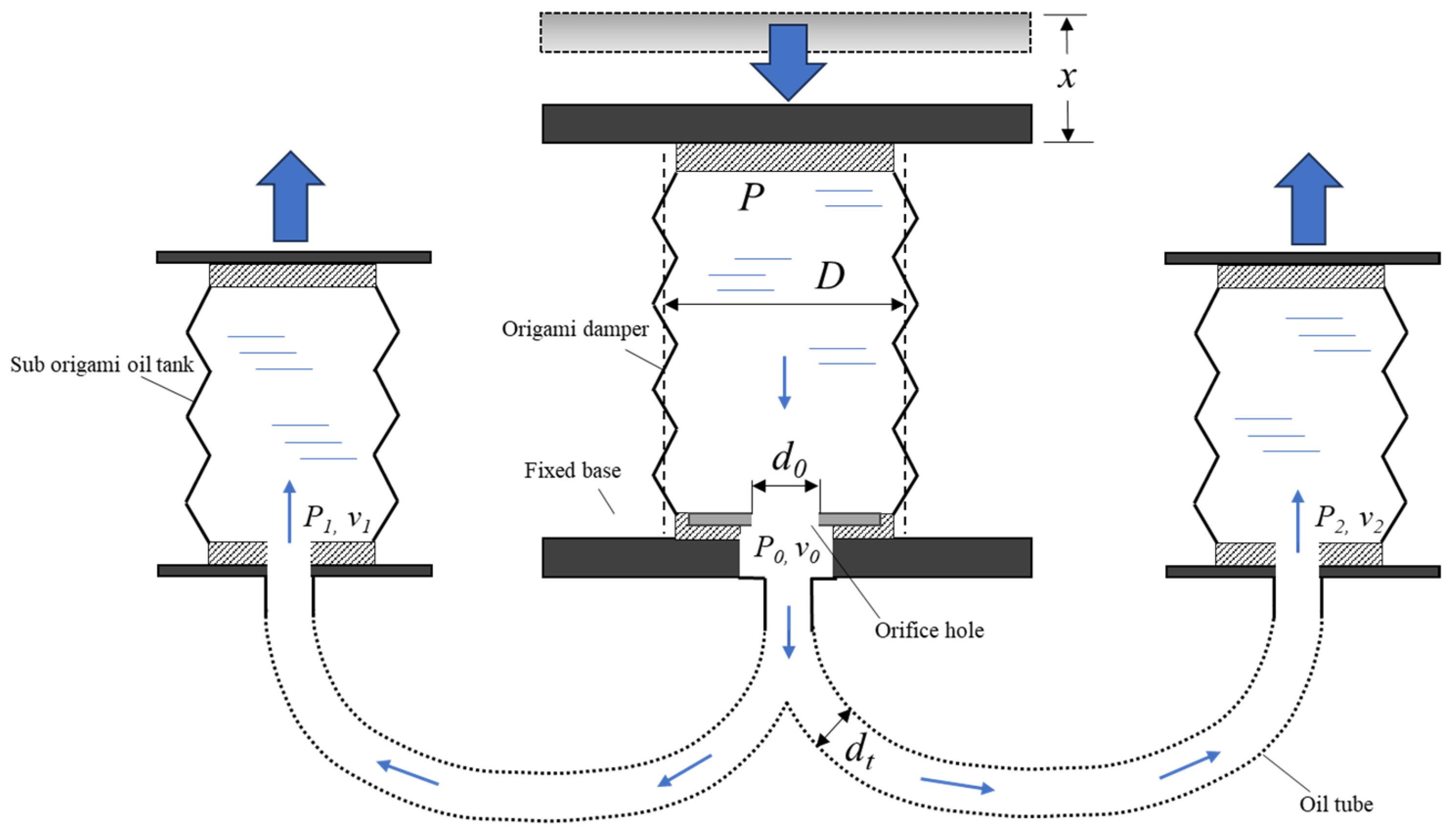
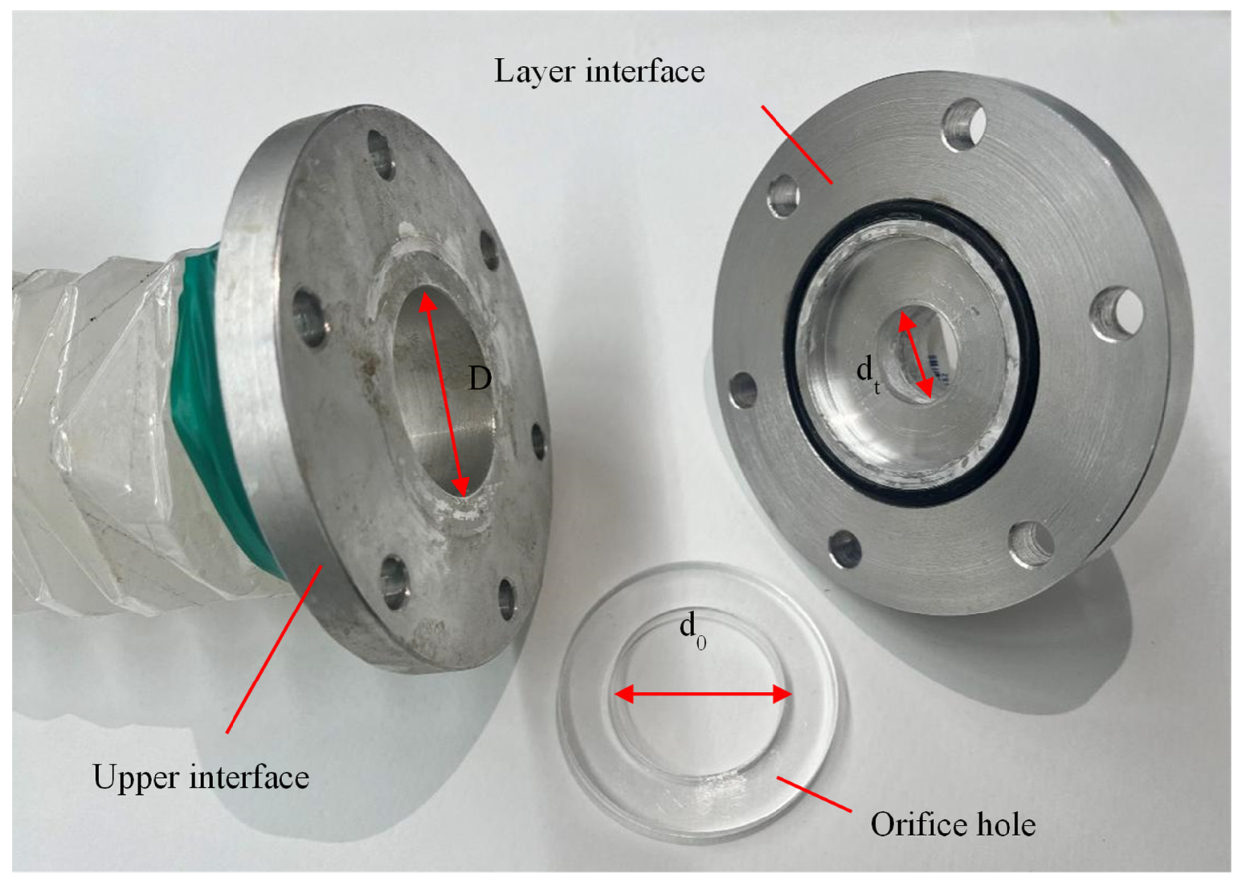
2.2. Damping Force Analysis of Bifurcated Origami Hydraulic Damper

To investigate the mechanical properties of the bifurcated origami hydraulic damper, we verified the damper on the test stand and simplified the analytical model, as shown in Figure 8.
For the purposes of discussion, let D represent the center diameter of the origami hydraulic damper, d0 is the orifice hole leading from the damper to the oil tube, and dt is the diameter of the oil tube. The pressure at the top surface of the damper is denoted as P, while P0 is the pressure at the orifice hole at the bottom of the damper. Additionally, P0 and v0 indicate the pressure and flow rate at the orifice hole’s outlet, respectively, whereas P1 and v1 represent the pressure and flow rate at the ends of several oil tubes, analogous to P2 and v2.
The flow rate of the hydraulic oil through an orifice hole in the body of the bifurcated origami hydraulic damper can be determined using the following equation [30]:
Q = c A 1 2 ρ P P 0 ,
where c is the flow coefficient, which is assumed to be 0.61, A1 is the cross-sectional area of the orifice hole, and ρ is the density of the internal oil.
Q = ν o A 1
By substituting this into Equations (2) and (3), the following equation was obtained:
ν o A 1 = c A 1 2 ρ P P 0
According to Equation (4), the pressure inside the bifurcated origami hydraulic damper can be expressed using the following equation:
P = P o + ρ v o 2 2 c 2
The hydraulic oil flows from the orifice hole through the oil tube to each branch hydraulic tank, and the pressure loss in this process can be calculated using the Darcy–Weisbach equation [30]:
P o P 1 P 2 = λ ρ 2 d t L 1 v 1 2 + L 2 v 2 2
Here, λ is the friction coefficient of the oil tube, and L denotes the length of each oil tube. The pressure drop resulting from the sudden expansion of the cross-sectional area when the hydraulic fluid enters each branch origami tank from the tubes can be calculated as follows [30]:
P 1 = k c ρ ν 1 2 2
P 2 = k c ρ ν 2 2 2 ,
where k c is the loss factor.
By reorganizing Equations (6)–(8), the following equation can be obtained:
P o = λ ρ 2 d t L 1 v 1 2 + L 2 v 2 2 + k c ρ 2 v 1 2 + v 2 2
The relationship between the flow rate at the top of each branch of the origami hydraulic damper and that at the lower part of the orifice hole can be expressed as follows:
v 0 = D 2 d 0 2 x ˙
v 0 d 0 2 = d t 2 v 1 + d t 2 v 2
As shown in Figure 8, the inner diameter of the branch hydraulic tank oil tube is dt. The ratio relationship of the flow rate of each branch is set as shown in Equation (11).
v 1 v 2 = k
Substituting Equation (12) into Equation (11) yields the following equation:
v 2 = v 0 d 0 2 d t 2 k + 1 = D 2 0 2 d t 2 k + 1 2
Summarizing Equations (13), (9), and (5) yields the following equation:
P = λ ρ v 0 2 0 4 2 d t 5 k + 1 2 L 1 k 2 + L 2 + k c ρ v 0 2 0 4 2 d t 4 k + 1 2 k 2 + 1 + ρ v 0 2 2 c
Substituting Equation (10) into Equation (14) yields the following equation:
P = λ ρ D 4 2 d t 5 k + 1 2 L 1 k 2 + L 2 x ˙ 2 + k c ρ D 4 2 d t 4 k + 1 2 k 2 + 1 x ˙ 2 + ρ D 4 2 c x ˙ 2
The average cross-sectional area of the bifurcated origami hydraulic damper is given by Equation (16):
A 2 = π D 2 4
The force is expressed by the following equation, based on the actual use of the bifurcated origami hydraulic damper:
F d a m p e r = π ρ D 6 8 [ λ d t 5 k + 1 2 L 1 k 2 + L 2 + k c d t 4 k + 1 2 k 2 + 1 + 1 C 2 d 0 4 ] x ˙ 2
Equation (17) shows that a nonlinear relationship exists between the force and velocity of the bifurcated origami hydraulic damper. The coefficient part of Equation (17) can now be calculated as the new bifurcated origami hydraulic damper coefficient, as shown in the following equation:
c d a m p e r = π ρ D 6 8 [ λ d t 5 k + 1 2 L 1 k 2 + L 2 + k c d t 4 k + 1 2 k 2 + 1 + 1 C 2 d 0 4 ]
Therefore, the damping force of the bifurcated origami hydraulic damper is expressed as follows:
F d a m p e r = c d a m p a e r x ˙ 2
Considering the damping force of the bifurcated origami hydraulic damper, the motion equation of the vibration system is expressed as follows:
m x ¨ + c x ˙ + c d a m p e r x ˙ 2 + k x = m x ¨ e
where m is the weight of the mass block, c is the damping coefficient owing to friction, k is the stiffness coefficient of the elastic spring, and x ¨ e is the external vibration acceleration. Equation (18) shows that the damping coefficient of the bifurcated origami damper is related to the center diameter of the bifurcated origami hydraulic damper, the diameter and the length of the pipe, the density of the liquid, and the diameter of the orifice hole. Together, they form the damping coefficient c d a m p e r . Therefore, the motion equation of a vibration system with a bifurcated origami hydraulic damper contains a motion velocity squared term, which is a nonlinear differential equation.
For numerical analysis, the motion Equation (20) is rewritten as the standard Runge–Kutta equation:
x ˙ t = c m x ˙ c d a m p e r m x ˙ 2 k m x x ¨ e
x t = x ˙
Applying the Runge–Kutta iterative analysis to Equations (21) and (22), as shown in the following equations, yields the vibrational velocity solution along the time series.
x ˙ 0 , x ˙ 1 , x ˙ 2 , x ˙ 3 , , x ˙ n
Additionally, the respective solutions for motion acceleration can be derived from the following equations:
x ¨ = x ˙ t
x ¨ 0 , x ¨ 1 , x ¨ 2 , x ¨ 3 , , x ¨ n
The actual orifice hole at the lower end of the bifurcated origami hydraulic damper and its cross-section are shown in Figure 9 and Figure 10, respectively. The detailed configuration parameters of the bifurcated origami hydraulic damper experimental setup are presented in Table 1.
As depicted in Table 1, the average diameter of the origami structures is 45 mm. To investigate the damping effect of the bifurcated origami hydraulic damper, four acrylic ring plates with diameters of 40, 35, 30, and 25 mm were prepared. The orifice hole size in the bifurcated origami hydraulic damper could be adjusted by securing the acrylic ring plate to the mass block.

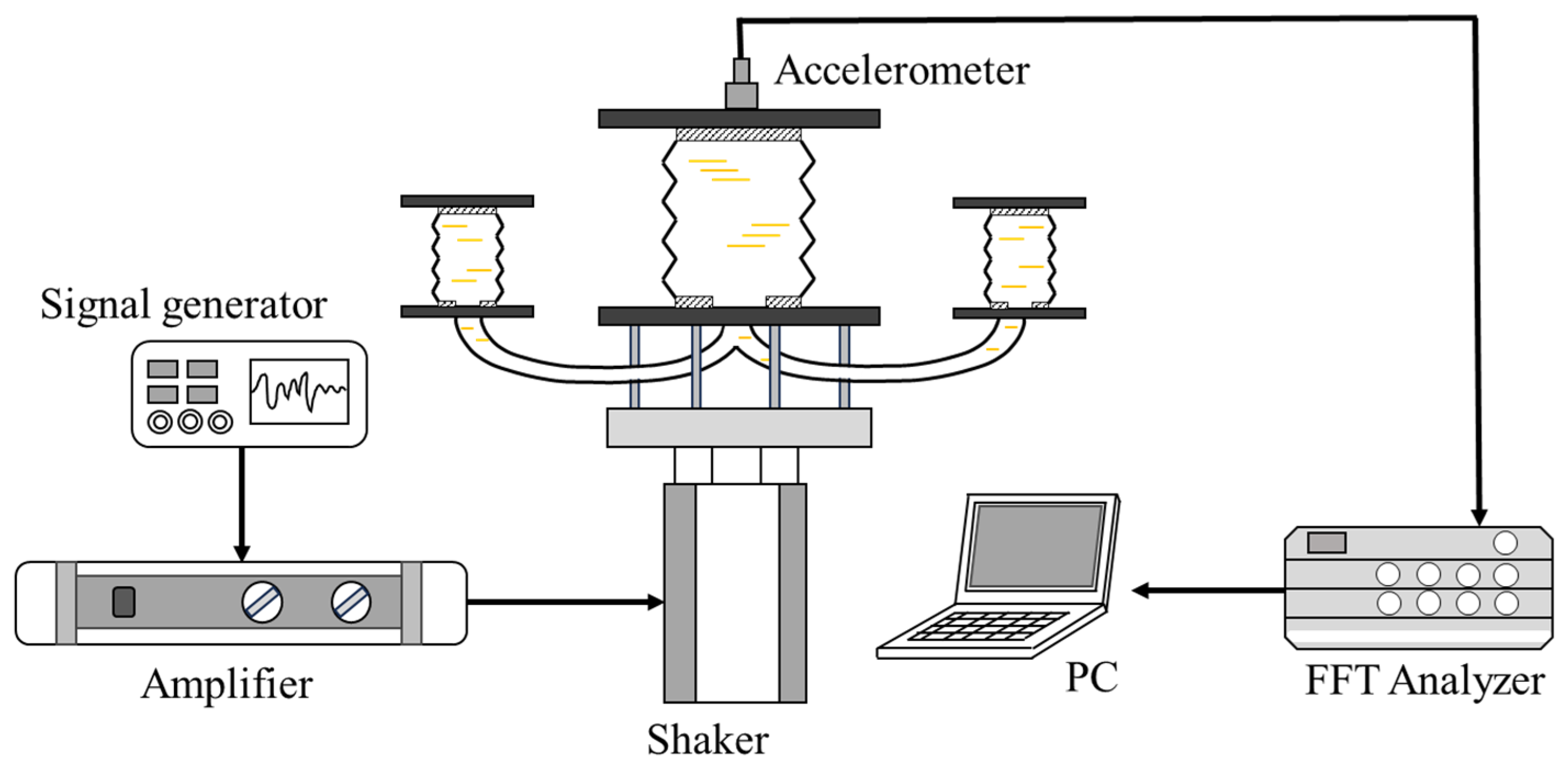
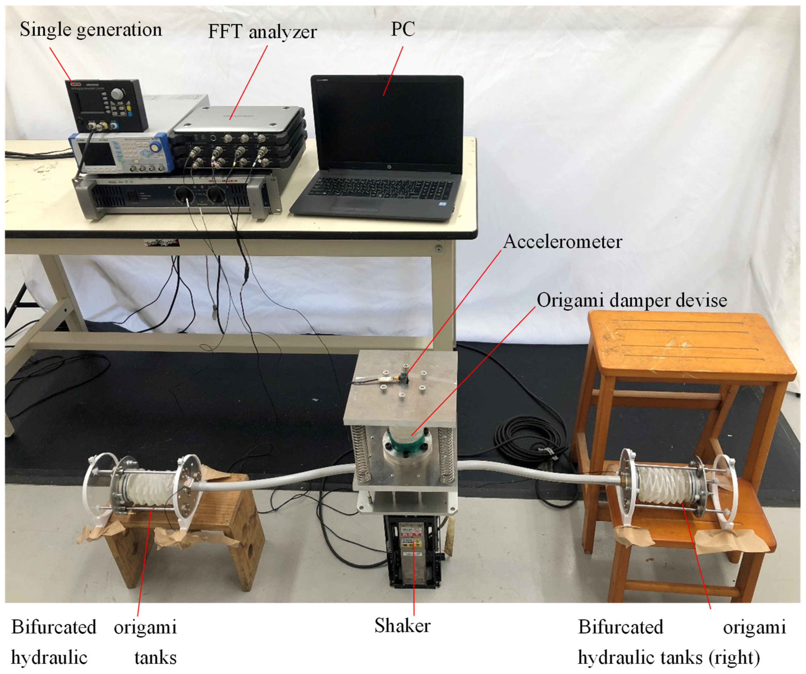
2.3. Vibration Verification Experiment

The vibration test system developed to verify the damping effect of the bifurcated origami hydraulic damper consisted of a shaker table, an amplifier, a signal generator, an accelerometer, an FFT analyzer, and a personal computer to process the results, as shown in Figure 11.
The actual measurements were performed according to the flowchart shown in Figure 12. First, vibration signals were generated with the signal generator and sent to the amplifier. The amplified vibration signal was then sent to the shaker table to induce the vibration model of the bifurcated origami hydraulic damper fixed on the shaker table.
In addition, the acceleration signal at the upper face of the bifurcated origami hydraulic damper was detected using an acceleration sensor and recorded using an FFT analyzer. Finally, the measured vibration response results were computed and output. Table 2 lists the detailed parameters of the components of the experimental setup and measurement equipment.
For the purpose of this study, measurement experiments and numerical analyses were conducted on the bifurcated origami hydraulic damper vibration model system shown in Figure 12 using sinusoidal signals (frequency 6.2 Hz, intensity 1.2 m/s2), and the results of the vibration acceleration are summarized in Figure 13. In the figure, the solid blue line represents the experimentally measured value, and the red dashed line represents the numerically analyzed value. These two results are in agreement with each other.

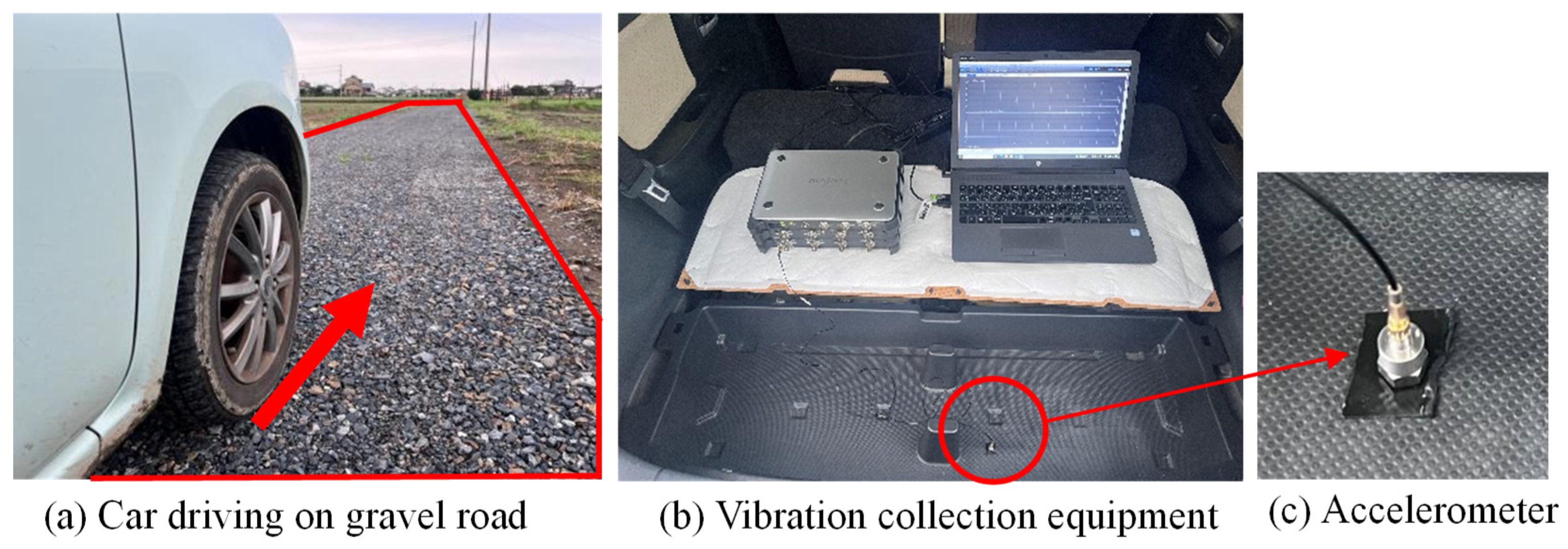
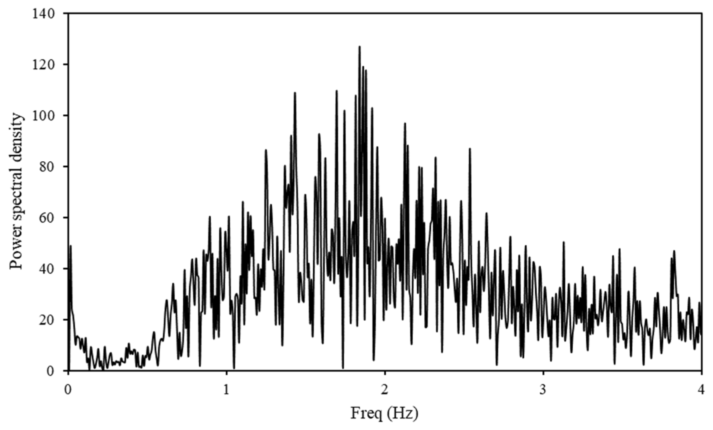
2.4. Vibration Wave When Driving on Gravel Road

To verify the damping effect of the bifurcated origami hydraulic damper in a complex vibration environment, a vehicle traveling on a real gravel road was used, as shown in Figure 14a. Inside the vehicle traveling on a real gravel road, we prepared an acceleration sensor and a signal recording device. An acceleration sensor was installed inside the vehicle at a speed of 30 km/h (Figure 14b). Random vibration signals on a real road were measured using an acceleration sensor installed inside the vehicle, as shown in Figure 14c.
The acceleration waveforms and Fourier-transform frequency components obtained from the actual measurements are shown in Figure 15 and Figure 16, respectively. As shown in the figures, the vibration signals were randomly distributed, and the main frequency components were concentrated at approximately 2.0 Hz.

3. Results and Discussion

To perform a quantitative assessment of the response vibration of the mass blocks of a vibration system when subjected to random signal vibrations on a real gravel pavement, we applied the standard deviation values calculated using the following formula to the results of the kinematic acceleration obtained from the vibration experiments.
S = 1 N i = 1 N a i a 0 2 ,
where a i is the measured acceleration, a 0 is the average acceleration, and N is the number of experimental samples.

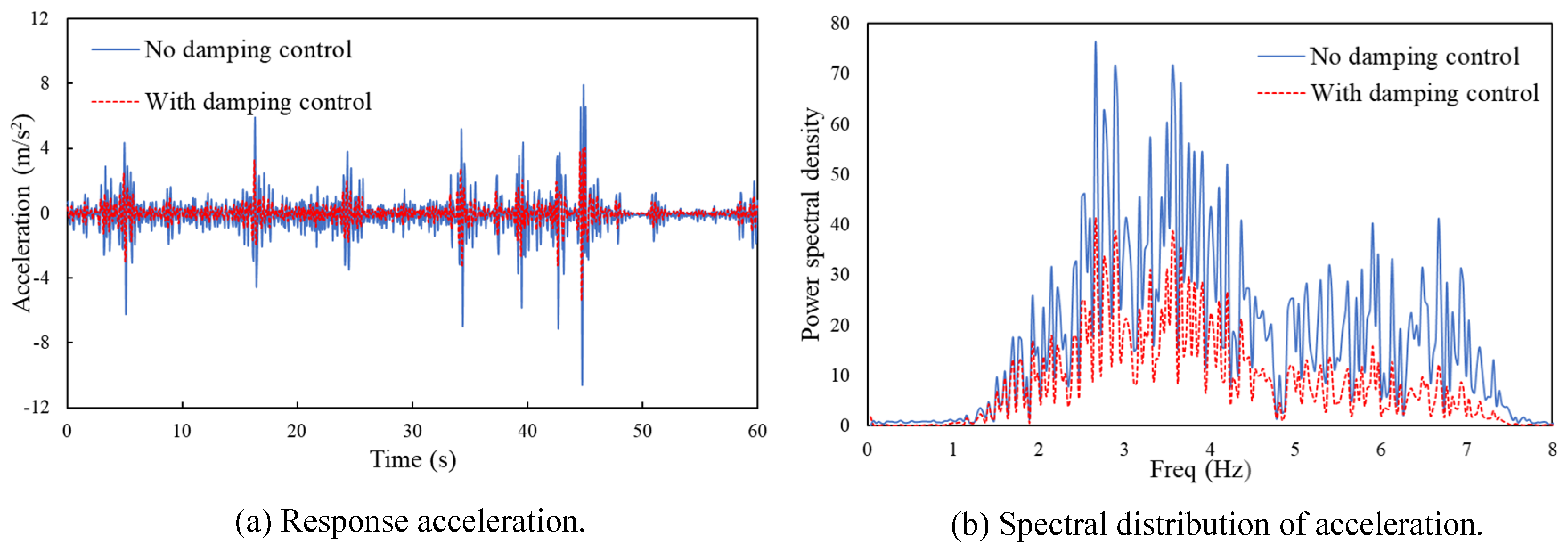
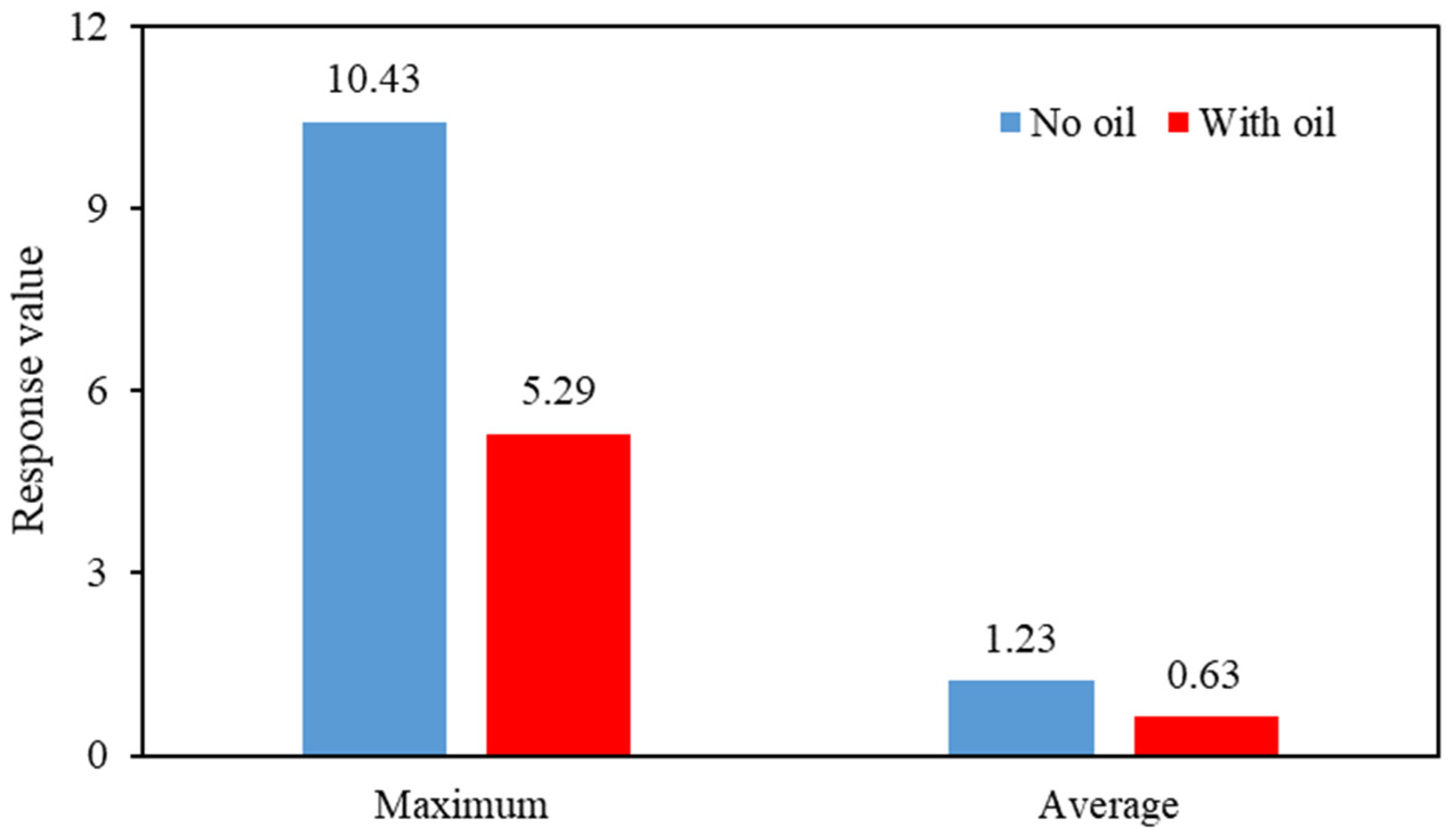
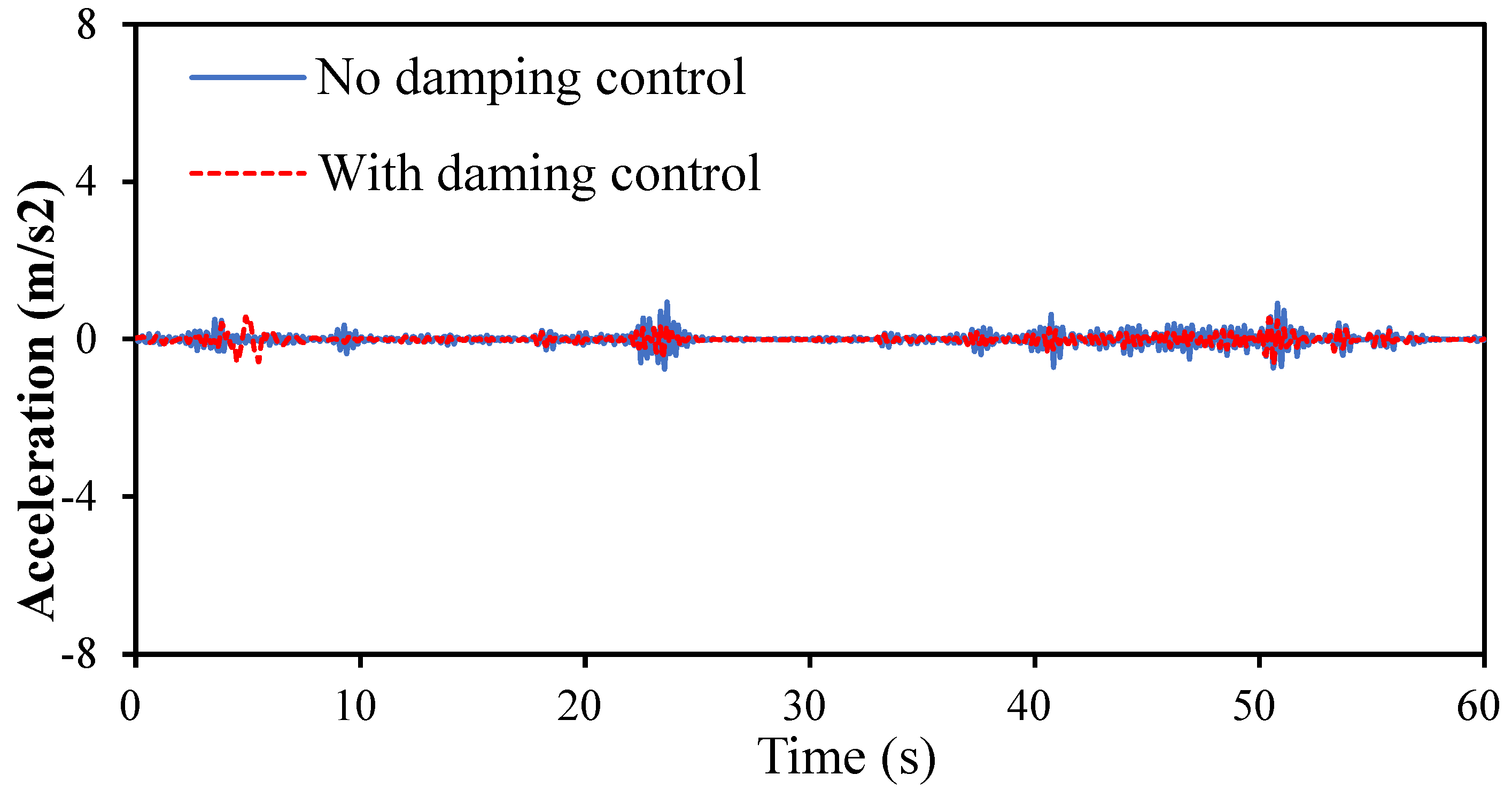
3.1. Damping Effects

In this study, an experimental setup was vibrated using recorded gravel road vibration waves running on a vibration test stand. The acceleration results for the vibrating mass block with an orifice hole measuring 40 mm are shown in Figure 17. The blue solid line indicates the acceleration response without oil injection, and the red dashed line indicates the acceleration response with oil injection.
As shown in Figure 17a, the acceleration response with oil injection is smaller than that without oil injection. In addition, to investigate the damping effect in the frequency domain, as shown in Figure 17b, we performed Fourier transforms on the acceleration measurements separately, and the results showed that the damping effect was small in each frequency domain. This indicates that the bifurcated origami hydraulic damper has a damping effect.
To further assess the damping effect quantitatively, the acceleration measurements in Figure 17 were substituted into Equation (26), and the standard deviation of acceleration was calculated separately. The results are shown in Figure 18.
Figure 18 shows that the maximum value of the response acceleration was reduced by 49.28%, and the standard deviation was reduced by 48.95%, indicating that the bifurcated origami hydraulic damper has a vibration-damping effect.

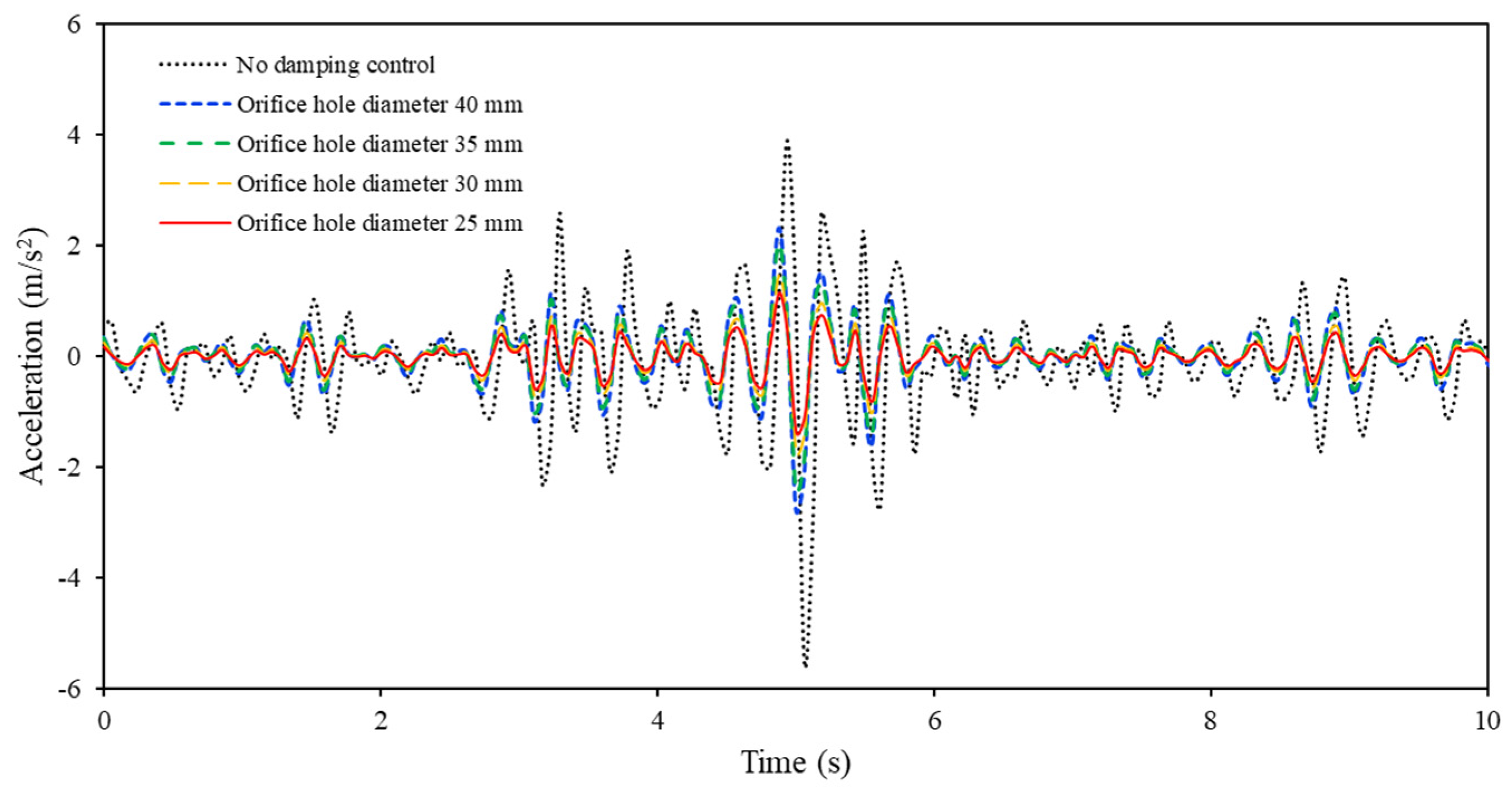
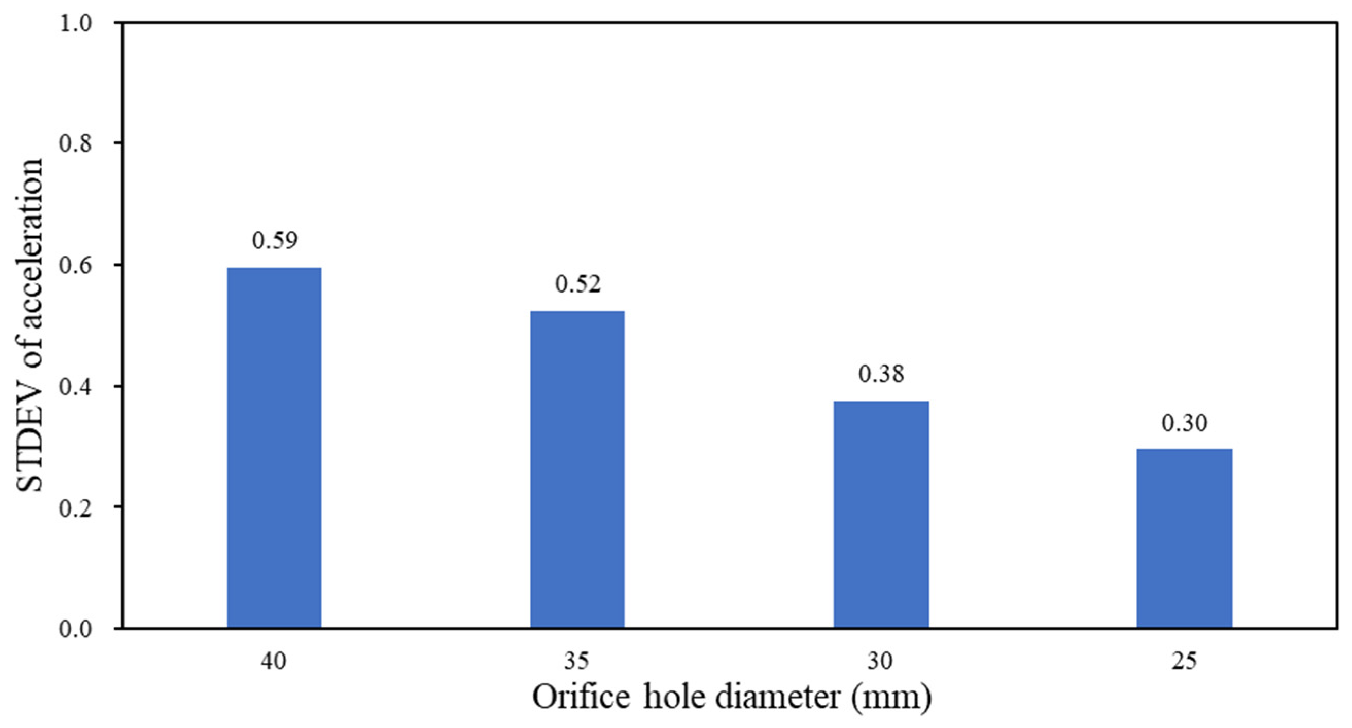
3.2. Effects of Orifice Holes

The damping effect is significant, evident from the sizes of the orifice holes through which hydraulic fluid passes in the bifurcated origami hydraulic damper. To investigate this, the acceleration of vibration test responses was measured for orifice hole diameters d0 of 40, 35, 30, and 25 mm, as depicted in Figure 10. Figure 19 confirms that changes in orifice hole diameter influence the acceleration response.
To compare these effects quantitatively, Figure 20 summarizes the standard deviation values corresponding to each orifice hole experimental case (Figure 19). The standard deviation values were 0.59, 0.52, 0.38, and 0.30 for orifice hole diameters of 40, 35, 30, and 25 mm, respectively. As the orifice diameter decreased, the standard deviation of the response acceleration decreased nearly linearly.

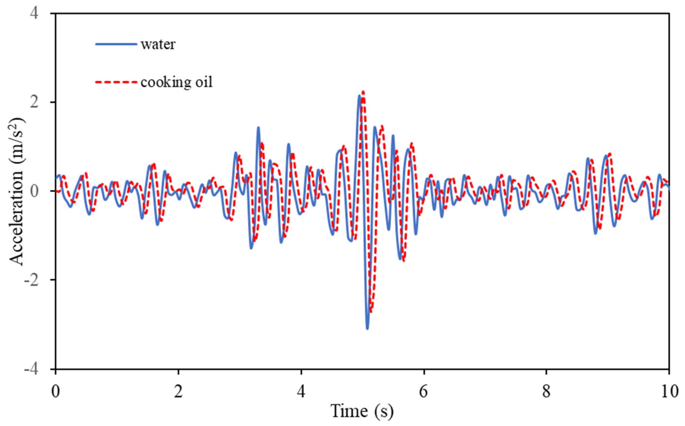
3.3. Effects of Liquid Types

Based on the characteristics of the liquid filled in the bifurcated origami hydraulic damper, it was hypothesized that it would affect the damping effect and that the damping effect of using cooking oil would be relatively better than that of using water. For this study, we set up two experimental cases, water and cooking oil, in the bifurcated origami hydraulic damper and performed vibration tests; the results are shown in Figure 21. A comparison of the acceleration data for the vibration masses shows that the standard deviation is 0.61 with water and 0.57 with cooking oil, which is a reduction of 5.99%.

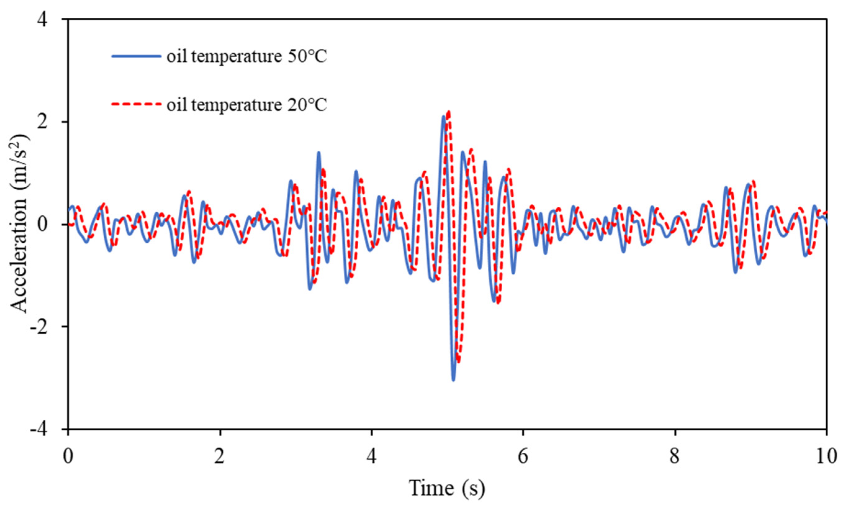
3.4. Effects of Temperature

Furthermore, considering weather changes or the repeated use of bifurcated origami hydraulic dampers over a long period, a continuously increasing internal fluid temperature can likely affect the damping effect. To investigate this, we performed vibration experiments by heating cooking oil and filling it up to 20 and 50 °C, and the results are shown in Figure 22. A comparison of the results showed that the standard deviation of cooking oil at 20 °C was 0.60, whereas that at 50 °C was 0.57, which is a reduction of 4.25%.
Here, the average density of cooking oil was approximately 924 kg/m3 at 20 °C and 890 kg/m3 at 50 °C. When the temperature of cooking oil increased from 20 to 50 °C, the density difference changed by 3.6%. Meanwhile, the observed difference in the damping effect of the bifurcated origami hydraulic damper was 4.25%. This suggests that the influences of hydraulic oil type and temperature are relatively minor.

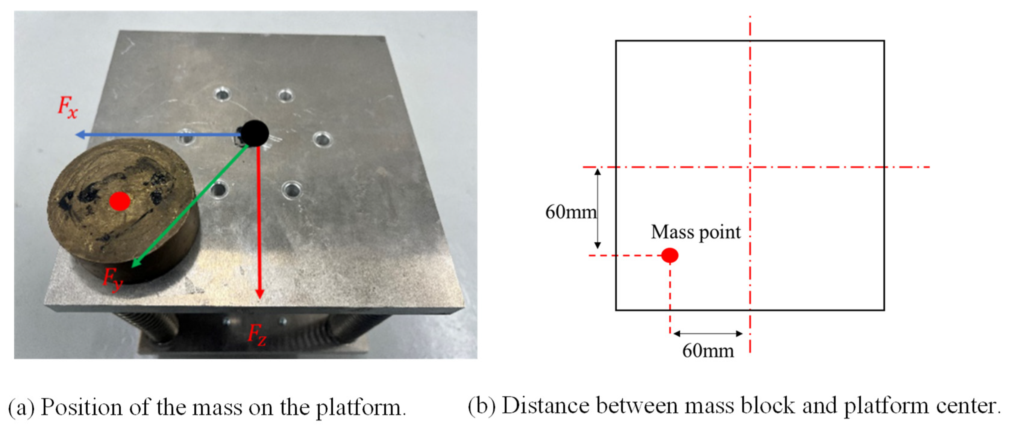
3.5. Effects of Vibration Loads

The damping effect of the bifurcated origami hydraulic damper in complex environments was determined when it was simultaneously subjected to multiple vibration forces from different directions. Therefore, as shown in Figure 23a, the mass block was set at a certain distance from the center of the platform to make the platform vibrate at multiple angles.
For this study, as shown in Figure 23b, we placed a mass block weighing 834 g at a distance of 60 mm from the horizontal and vertical centers of the device and conducted vibration experiments using vibration waves on a gravel road with and without oil injection. We installed a three-dimensional accelerometry sensor on the device. The results for the x, y, and z directions are shown in Figure 24, Figure 25 and Figure 26. In addition, the acceleration vectors in the three directions were added to the same time-step point, and the obtained vector-norm data are shown in Figure 27.
Figure 27 shows that the acceleration values with oil injection were lower than those without. In addition, the standard deviation of the case with oil injection was 53.44% smaller than that of the case with no oil injection. Thus, the bifurcated origami hydraulic damper has a damping effect in complex environments when simultaneously subjected to multiple vibratory forces from different directions.

4. Conclusions and Future Work

This study introduced a design for a bifurcated origami hydraulic damper. The following conclusions were drawn from theoretical analyses and validation experiments:
(1)
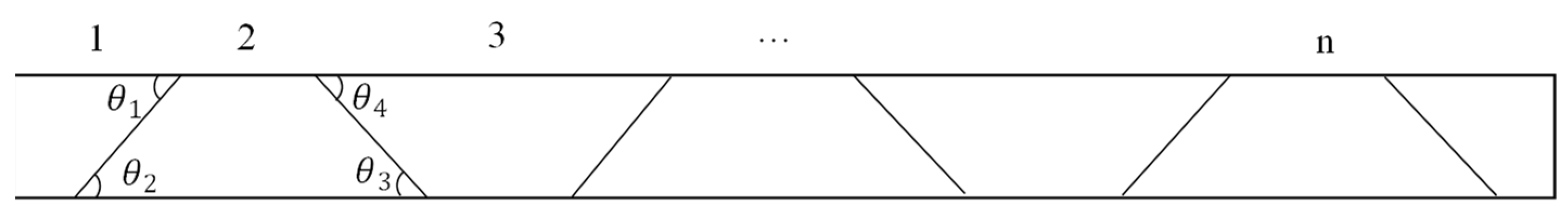
Through analysis of the mechanical characteristics and derivation of a new damping force formula, it was demonstrated that the damping force of the bifurcated origami hydraulic damper is directly proportional to the square of the velocity of motion;
(2)
A vibration test apparatus incorporating a bifurcated origami hydraulic damper was developed. Summarizing the main components—mass block as the damping object, elastic spring device, bifurcated origami hydraulic damper, and friction-induced damping elements—we established control equations for nonlinear motion and proposed a numerical analysis approach using the Runge–Kutta method. Numerical results aligned well with actual experimental measurements;
(3)
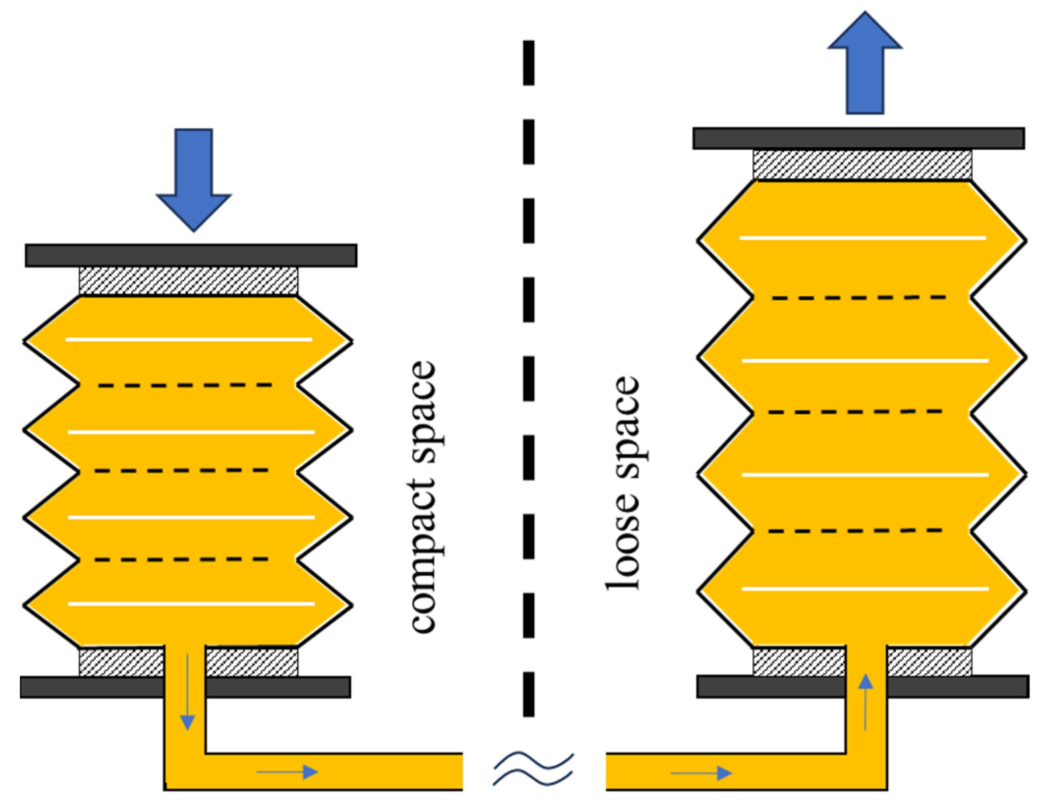
Vibration experiments were conducted using random vibration waves recorded on a gravel road. Results showed that damping effectiveness was nearly halved when oil was injected into the bifurcated origami hydraulic damper compared with conditions without oil injection, underscoring the significant vibration-damping capability of the damper;
(4)
The impact of orifice hole diameter, a critical design parameter of the bifurcated origami hydraulic damper, on damping performance was investigated experimentally. Collision-damping effectiveness decreased as the orifice hole diameter increased;
(5)
Validation experiments examined the influence of hydraulic oil type and temperature within the bifurcated origami hydraulic damper. The effects of oil type and temperature on damping effectiveness were found to be 5.99% and 4.25%, respectively, indicating a relatively minor impact on collision-damping performance;
(6)
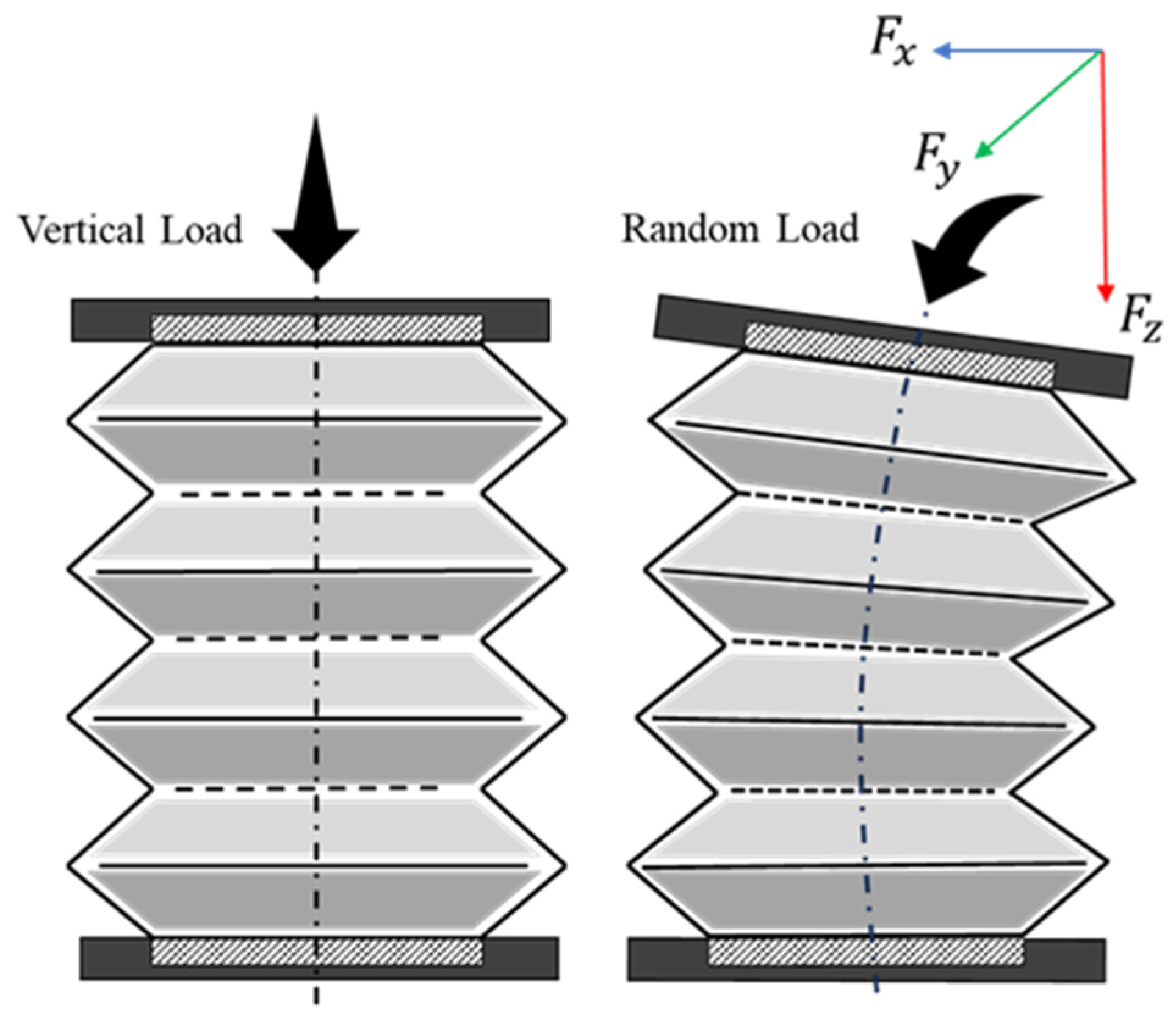
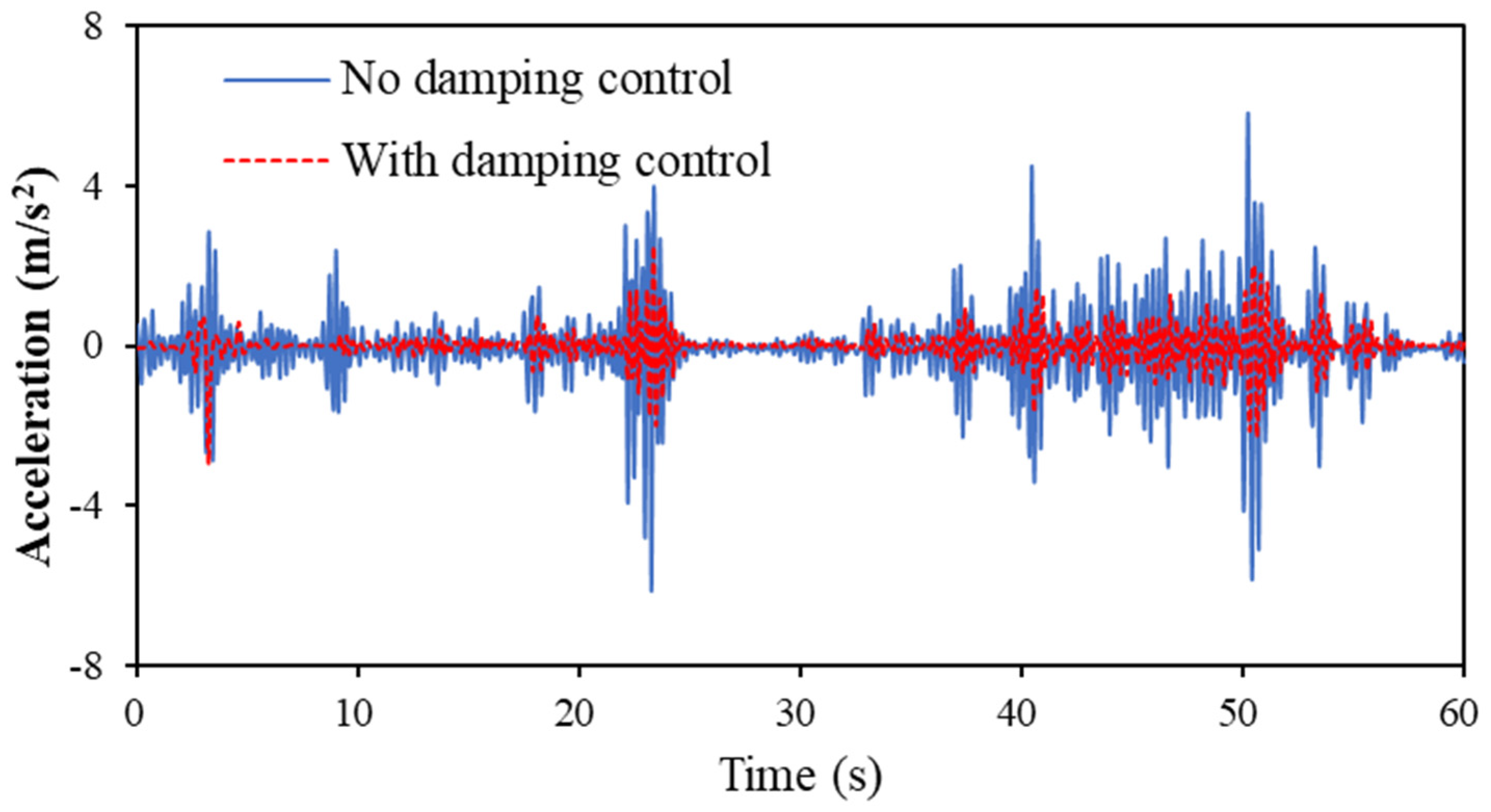
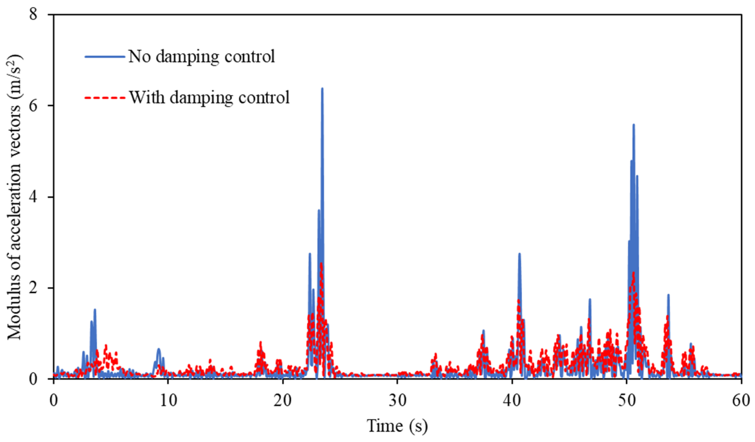
The response acceleration values of the mass blocks were measured using a three-dimensional accelerometer under asymmetric vibration with off-center loads. It was observed that the standard deviation of the response acceleration values was reduced by 53.44% compared with those without oil injection. This finding highlights the effectiveness of the bifurcated origami hydraulic damper in managing vibrations in complex environments.
The bifurcated origami structure damper proposed in this paper allows for better adjustment of the origami posture according to specific load directions compared with conventional hydraulic dampers. Additionally, due to its unique characteristics, the oil inside the main origami damper can be discharged through pipes to the oil origami tank placed in a less constrained area, thereby enhancing space utilization efficiency. These dampers do not require complex mechanical connection structures, offering significant advantages in lightweight and compact spaces.
However, due to the bifurcated origami hydraulic damper constructed with a thin origami structure, it is difficult to apply to large loads such as heavy trucks. Future research should focus on improving the performance of bifurcated origami hydraulic dampers and on promoting further research on their practical applications in automobile suspensions and other areas.

Author Contributions

Writing—original draft preparation, J.G.; writing—review and editing, J.G. and X.Z.; data curation, B.Z.; investigation, Y.L.; software, W.Z.; conceptualization, W.Z. and X.Z.; methodology, J.G. and B.Z.; validation, Y.L. All authors have read and agreed to the published version of the manuscript.

Funding

This research received no external funding.

Institutional Review Board Statement

Not applicable.

Informed Consent Statement

Not applicable.

Data Availability Statement

The data are available in a publicly accessible repository.

Conflicts of Interest

The authors declare no conflicts of interest.

References

  1. Wu, Z.; Xu, G. Modeling and analysis of a hydraulic energy-harvesting shock absorber. Math. Probl. Eng. 2020, 2020, 1580297. [Google Scholar] [CrossRef]
  2. Wu, Z.; Xu, G.; Yang, H.; Li, M. Analysis of damping characteristics of a hydraulic shock absorber. Shock Vib. 2021, 2021, 8883024. [Google Scholar] [CrossRef]
  3. Rao, M.D.; Echempati, R.; Nadella, S. Dynamic analysis and damping of composite structures embedded with viscoelastic layers. Compos. Part B Eng. 1997, 28, 547–554. [Google Scholar] [CrossRef]
  4. Rikards, R.; Chate, A.; Barkanov, E. Finite element analysis of damping the vibrations of laminated composites. Comput. Struct. 1993, 47, 1005–1015. [Google Scholar] [CrossRef]
  5. Huang, Y.; Sturt, R.; Willford, M. A damping model for nonlinear dynamic analysis providing uniform damping over a frequency range. Comput. Struct. 2019, 212, 101–109. [Google Scholar] [CrossRef]
  6. Konieczny, Ł. Analysis of simplifications applied in vibration damping modelling for a passive car shock absorber. Shock. Vib. 2016, 2016, 6182847. [Google Scholar] [CrossRef]
  7. Burdzik, R.; Konieczny, Ł. Research on structure, propagation and exposure to general vibration in passenger car for different damping parameters. J. Vibroeng. 2013, 15, 1680–1688. [Google Scholar]
  8. Verros, G.; Natsiavas, S.; Stepan, G. Control and dynamics of quarter-car models with dual-rate damping. J. Vib. Control 2000, 6, 1045–1063. [Google Scholar] [CrossRef]
  9. Hemanth, K.; Kumar, H.; Gangadharan, K.V. Vertical dynamic analysis of a quarter car suspension system with MR damper. J. Braz. Soc. Mech. Sci. Eng. 2017, 39, 41–51. [Google Scholar] [CrossRef]
  10. Lafarge, B.; Cagin, S.; Curea, O.; Perret, A.H. From functional analysis to energy harvesting system design: Application to car suspension. Int. J. Interact. Des. Manuf. 2016, 10, 37–50. [Google Scholar] [CrossRef]
  11. Guntur, H.L.; Hendrowati, W.; Syuhri, S.N.H. Designing hydro-magneto-electric regenerative shock absorber for vehicle suspension considering conventional-viscous shock absorber performance. J. Mech. Sci. Technol. 2020, 34, 55–67. [Google Scholar] [CrossRef]
  12. Hu, G.; Yi, F.; Liu, H.; Zeng, L. Performance analysis of a novel magnetorheological damper with displacement self-sensing and energy harvesting capability. J. Vib. Eng. Technol. 2021, 9, 85–103. [Google Scholar] [CrossRef]
  13. Niu, M.; Jiang, H. Research on the Dynamic Model with Magnetorheological Damper. In Proceedings of the First Symposium on Aviation Maintenance and Management-Volume I; Springer: Berlin/Heidelberg, Germany, 2014; pp. 323–330. [Google Scholar]
  14. Go, C.-G.; Sui, C.-H.; Shih, M.-H.; Sung, W.-P. A Linearization Model for the Displacement Dependent Semi-active Hydraulic Damper. J. Vib. Control. 2010, 16, 2195–2214. [Google Scholar] [CrossRef]
  15. Azimi, M.; Rasoulnia, A.; Lin, Z.; Pan, H. Improved semi-active control algorithm for hydraulic damper-based braced buildings. Struct. Control Health Monit. 2017, 24, e1991. [Google Scholar] [CrossRef]
  16. Sui, C.; Go, C.; Shih, M.; Sung, W. Validity of the displacement dependent semi-active hydraulic damper used in a structure. J. Vib. Control 2011, 17, 579–587. [Google Scholar] [CrossRef]
  17. Lv, C.; Krishnaraju, D.; Konjevod, G.; Yu, H.; Jiang, H. Origami based Mechanical Metamaterials. Sci. Rep. 2014, 4, 5979. [Google Scholar] [CrossRef] [PubMed]
  18. Paula, Á.-G.; Domínguez, M. Origami. Deployable structures. Técnica Ind. 2023, 334, 50–57. [Google Scholar]
  19. Leanza, S.; Wu, S.; Sun, X.; Qi, H.J.; Zhao, R.R. Active Materials for Functional Origami. Adv. Mater. 2023, 36, 2302066. [Google Scholar] [CrossRef] [PubMed]
  20. Xi, K.; Chai, S.; Ma, J.; Chen, Y. Multi-Stability of the Extensible Origami Structures. Adv. Sci. 2023, 10, 2303454. [Google Scholar] [CrossRef] [PubMed]
  21. Kim, T.H.; Jang, K.I.; Lee, D.Y.; Han, J.H. Rigid-Foldable Polyhedral Origami. AIAA J. 2023, 61, 5645–5657. [Google Scholar] [CrossRef]
  22. Zhang, X.; Lu, G.; Wang, S.; Durandet, Y. Mechanical Characteristics of Graded Origami Bellows under Axial Tension. Front. Phys. 2023, 11, 1304426. [Google Scholar] [CrossRef]
  23. Huang, Z.; Wei, C.; Dong, L.; Wang, A.; Yao, H.; Guo, Z.; Mi, S. Fluid-driven hydrogel actuators with an origami structure. iScience 2022, 25, 104674. [Google Scholar] [CrossRef]
  24. Ye, S.; Zhao, P.; Zhao, Y.; Kavousi, F.; Feng, H.; Hao, G. A Novel Radially Closable Tubular Origami Structure (RC-ori) for Valves. Actuators 2022, 11, 243. [Google Scholar] [CrossRef]
  25. Lu, L.; Li, X. Ring origami spring capable of eversion morphing. J. Mech. Robot. 2024, 16, 081004-1. [Google Scholar]
  26. Hu, Q.; Li, J.; Tao, J.; Dong, E.; Sun, D. Inverse Origami Design Model for Soft Robotic Development. Soft Robot. 2023, 11, 131–139. [Google Scholar] [CrossRef]
  27. Li, Y.; Huang, H.; Li, B. Design of a Deployable Continuum Robot Using Elastic Kirigami-Origami. IEEE Robot. Autom. Lett. 2023, 8, 8382–8389. [Google Scholar] [CrossRef]
  28. Guan, J.; Zuo, J.; Zhao, W.; Gomi, N.; Zhao, X. Study on Hydraulic Dampers Using a Foldable Inverted Spiral Origami Structure. Vibration 2022, 5, 711–731. [Google Scholar] [CrossRef]
  29. Guan, J.; Yao, Y.; Zhao, W.; Hagiwara, I.; Zhao, X. Development of an Impact Energy Absorption Structure by an Arc Shape Stroke Origami Type Hydraulic Damper. Shock. Vib. 2023, 2023, 4578613. [Google Scholar] [CrossRef]
  30. Cengel, Y.A.; Cimbala, J.M. Fluid Mechanics: Fundamentals and Applications; McGraw-Hill: Noida, India, 2006. [Google Scholar]
Figure 1. Stroke comparison of conventional cylinder dampers and origami structures.
Applsci 14 06374 g001
Figure 2. Conceptual diagram of the origami hydraulic damper.
Applsci 14 06374 g002
Figure 3. Inner workings of bifurcated origami hydraulic damper.
Applsci 14 06374 g003
Figure 4. Closing the one unit of cylindrical origami structure.
Applsci 14 06374 g004
Figure 5. The folded one unit of origami structure.
Applsci 14 06374 g005
Figure 6. Main origami hydraulic damper device. (a) Polyethylene cylindrical tube. (b) Origami damper film. (c) Mian origami damper. (d) Spring frame. (e) Vibration test device.
Applsci 14 06374 g006
Figure 7. Bifurcated origami hydraulic tanks. (a) Bifurcated origami tanks. (b) the frame of bifurcated origami tank. (c) Assembly completed for the two bifurcated origami tanks. (d) Overall view of the test device.
Applsci 14 06374 g007
Figure 8. Experimental setup of the bifurcated origami hydraulic damper.
Applsci 14 06374 g008
Figure 9. The orifice hole structure at the lower end of the bifurcated origami hydraulic damper.
Applsci 14 06374 g009
Figure 10. Bottom interface orifice structure.
Applsci 14 06374 g010
Figure 11. Bottom interface orifice structure.
Applsci 14 06374 g011
Figure 12. Experimental setup for vibration testing using the bifurcated origami hydraulic damper.
Applsci 14 06374 g012
Figure 13. Comparison of the vibration displacement from the measurement experiment and numerical analysis results.
Applsci 14 06374 g013
Figure 14. Collection of the acceleration vibration waves when driving on a gravel road.
Applsci 14 06374 g014
Figure 15. Acceleration waveform measured during actual driving.
Applsci 14 06374 g015
Figure 16. Spectral distribution of acceleration waveform measured during actual driving.
Applsci 14 06374 g016
Figure 17. Measurement results when excited under the vibration waves on a gravel road.
Applsci 14 06374 g017
Figure 18. Comparison of the average and maximum response.
Applsci 14 06374 g018
Figure 19. Effect of different diameters of the orifice hole on the bifurcated origami damper.
Applsci 14 06374 g019
Figure 20. Relationship between the orifice hole diameter and the standard deviation of acceleration.
Applsci 14 06374 g020
Figure 21. Effect of liquid type on the bifurcated origami hydraulic damper.
Applsci 14 06374 g021
Figure 22. Effect of liquid temperature on the bifurcated origami hydraulic damper.
Applsci 14 06374 g022
Figure 23. Eccentrically placed mass block on the vibration platform and its weight mass.
Applsci 14 06374 g023
Figure 24. Comparison of the acceleration response of the bifurcated origami hydraulic damper on the x-axis.
Applsci 14 06374 g024
Figure 25. Comparison of the acceleration response of the bifurcated origami hydraulic damper on the y-axis.
Applsci 14 06374 g025
Figure 26. Comparison of the acceleration response of the bifurcated origami hydraulic damper on the z-axis.
Applsci 14 06374 g026
Figure 27. Comparison of the modulus of the sum of the acceleration vectors under multi-dimensional vibration.
Applsci 14 06374 g027
Table 1. Detailed parameters of the experiment conducted on the bifurcated origami hydraulic damper.
ItemsParameters
Spring K830 N/m
Mass block weight m1.62 kg
Average diameter of origami damper D45 mm
Orifice hole diameter do40 mm/35 mm/30 mm/25 mm
Orifice tube diameter dt12 mm
Oil tube length L350 mm
Coefficient   of   friction   of   oil   tube   λ 0.005
Orifice flow coefficient c0.61
Hydraulic   oil   density   ρ 910 kg/m3
Table 2. Detailed parameters of the experimental setup.
ItemsParameters
FFT analyzerOnosokki Corporation DS-3000
AccelerometerOnosokki NP-3572
ShakerSan-Esu SSV-60S
Signal generatorNF Corporation WF1973
AmplifierSan-Esu SVA-ST-30
Disclaimer/Publisher’s Note: The statements, opinions and data contained in all publications are solely those of the individual author(s) and contributor(s) and not of MDPI and/or the editor(s). MDPI and/or the editor(s) disclaim responsibility for any injury to people or property resulting from any ideas, methods, instructions or products referred to in the content.

