Article

Study on Deformation Control of Road-Deep Foundation Pit Passing under Elevated Subway Bridge

1
School of Civil Engineering, Beijing Jiaotong University, Beijing 100044, China
2
National Engineering Research Center of High-Speed Railway Construction Technology, Changsha 410075, China
3
China Railway Group Limited, Beijing 100039, China
4
School of Civil Engineering, Central South University, Changsha 410075, China
*
Author to whom correspondence should be addressed.
Appl. Sci. 2024, 14(14), 6357; https://doi.org/10.3390/app14146357
Submission received: 8 June 2024 / Revised: 13 July 2024 / Accepted: 17 July 2024 / Published: 21 July 2024
(This article belongs to the Special Issue Advances in Tunnel and Underground Engineering)

Abstract

This paper focuses on the application of pile foundation underpinning technology in a deep foundation pit of a subway Viaduct Project in Beijing. The study aims to address the engineering characteristics of the project, including a large number of new piles, a wide span of underpinning abutment, a long length of deep foundation pit, and a wide range of influences. This research utilizes field monitoring and numerical simulation methods to investigate the pile foundation underpinnings. The impact and management of road-deep foundation pit construction are considered, as well as their combined effect on subway viaducts and track structures. The primary accomplishments are as follows: (1) By analyzing the data from on-site deformation monitoring, it is evident that the pier exhibits maximum vertical deformation and maximum transverse deformation at the same location. The measuring locations are specifically situated on Pier 7# at the pile foundation underpinning. The maximum vertical and transverse deformations of the track are directly proportional to the maximum deformation of the pier. (2) By comparing the numerical simulation results with the field monitoring data, it is observed that although there is some discrepancy between the two, the deformation trend is largely consistent. This suggests that the numerical simulation analysis method is effective in reflecting the deformation of the bridge and track. (3) Through the numerical model and changing the values of the retaining structure parameters, the sensitivity of the pier deformation near the road foundation pit to the retaining structure parameters is systematically analyzed. The sensitivity of the pier deformation to the foundation pit parameters is as follows: the embedded depth insertion ratio of the retaining pile > the diameter of the retaining pile > the pile spacing.

1. Introduction

The building of a deep excavation can result in the deformation of the surrounding structure, causing uneven settlement of the nearby soil. This might lead to the deformation of the neighboring piling foundation and generate additional stress. Hence, it is imperative to investigate the regularity governing the deformation of undercrossing deep foundation pits or nearby existing bridge constructions. Additionally, it is crucial to compile a comprehensive list of engineering strategies that can efficiently manage the deformation of nearby pile foundations, thereby guaranteeing the safety of bridge structures during the construction of the deep excavation.
Most scholars, both domestic and international, utilize a mix of finite element numerical simulation and field monitoring data to validate the viability of the construction design scheme for the pile foundation underpinning technology study [1]. Li et al. [2] examined the stress transmission mechanism involved in the underpinning of a pile foundation, focusing on a specific project involving a bridge pile foundation underpinning. The investigation revealed that the settlement resulting from the underpinning of the pile foundation was around 20% to 30% of the overall settlement. Zhang et al. [3] confirmed the practicability and rationality of the pile support building plan. Iwasaki et al. [4] discovered that the excavation of the foundation pit can lead to a rise in the soil level, which in turn can impact the load-bearing capacity of the piling foundation. This conclusion was drawn from a study of real-life construction projects in Nagoya City. Zheng et al. [5] examined the changes in ground settlement resulting from pile cutting and the force-displacement characteristics of supporting piles during double-hole shallow excavation. Ground settlement around the foundation pit primarily happens during the pile-cutting stage under various excavation sequences. Xiang et al. [6] anticipated the extra subsidence of pile foundation resulting from tunnel excavation and precipitation and implemented anti-settlement retaining piles to manage the excessive negative consequences of tunnel excavation forecast. It has been discovered that support piles must be maintained for a certain duration after installation in order to successfully counteract the settling impact of tunnel excavation. Shan et al. [7] found that excavating the soil foundation can lead to settling of the foundation. By using supporting piles that have sufficient length and diameter and by ensuring they are embedded to an appropriate depth, it is possible to greatly reduce foundation settling. This is achieved by clarifying the way in which piles interact with the soil during the excavation of the foundation. Hu et al. [8] examined the criteria for making judgments and the crucial control areas for constructing pile foundations through underpinning. The study demonstrates that when the pile foundation underpinning scheme is implemented, the danger of tunneling increases. However, this risk can be managed more effectively in areas where the settlement of the center pier cannot be controlled adequately by solely implementing formation reinforcement methods. Based on this, the essential aspects of pile underpinning construction are presented. M. Makarchian et al. [9] utilized the finite element analysis technique to streamline the design process for pile foundations and put out a straightforward approach for building support piles by considering the interaction between the piles and the raft. Wu, Voznesensky, Djamila, and Xie et al. [10,11,12,13] have shown that the impact of underground construction on existing buildings can be controlled by reducing surface settlement. If the shield arch is near an existing building foundation, it is necessary to reinforce the foundation [14,15]. Patricia et al. [16] conducted a study on control piles. They utilized a mix of pile foundation underpinning and excavation technologies to expedite the building development process. A study in the literature [17] examined a preloading technique to analyze the load-displacement behavior of piles, the interaction between piles and soil during preloading, and the extra load induced by vertical extension through centrifugal testing. Ma et al. [18]. used the shield tunnel project of the Xi’an Subway as a case study. The bearing capacity of a single pile and the deformation of a joist were calculated based on their structural design. The calculation of the bearing capacity indicates that the reinforcement of the pile foundation is feasible. Xu et al. [19] examined the process of excavating a foundation pit beneath the bridge floor, as well as the use of a direct shield tunneling machine to cut through the raft bottom pile and pile during the building of the Shanghai Metro Line 10 tunnel. They also analyzed the mechanism by which the load is transferred within the bridge structure. It has been determined that the removal of the original piles has minimal impact on the bridge structure during excavation. Wang [20] conducted research on pile foundation underpinning to control building deformation and integrated it with foundation pit support to provide a comprehensive set of important technologies for developing underground spaces directly beneath cultural relic buildings. Huang [21] examined the alterations in the placement of pile foundations during the process of underpinning. The study discovered that increasing the thickness of grouting reinforcing rings can successfully reduce soil disturbance around the piles and manage the settlement of the pile foundation. Minimizing excavation steps can also reduce soil disturbance around the piles and enhance the stress status of the pile foundation throughout the underlying process. Zhang Qi [22] depends on a comprehensive pipe corridor foundation pit that is located next to the ongoing expressway bridge project. The study demonstrated that the excavation of a deep foundation pit will result in increased deformation and internal force in the piling foundation of the nearby highway bridge. Xiong Mengxin et al. [23] investigated the possibility of using passive underpinning technology in a pile foundation underpinning project with significant axial force. They conducted their study on an undercrossing viaduct in a foundation pit in Wuhan. The researchers examined the deformation characteristics of both the structure and the foundation pit under various processes. Fan Zhiwei [24] provided a concise overview of the main control technologies used for pile foundation underpinning in the context of the Dongxin Expressway bridge underpinning project beneath a subway tunnel in Guangzhou.
The current research on deep foundation pit construction reveals that most studies have focused on the impact of deep foundation pits on the surrounding environment and existing bridge structures. However, there is a lack of research on the influence of road deep foundation pits adjacent to or undercrossing bridges. Thus, it is crucial to analyze the engineering characteristics of a road deep foundation pit in Beijing that utilizes pile foundation underpinning technology to pass beneath an existing subway viaduct project. This study focuses on summarizing the key technologies involved, such as the simultaneous replacement of five bridge foundations, the replacement of a large number of new piles, the replacement of a large span of abutment, the construction of a long, deep foundation pit for the road, and the wide range of influence. Additionally, this study aims to investigate the impact of pile foundation underpinning and road foundation pit construction on the existing bridge and track structure. Additionally, references for similar work can also be provided.

2. Monitoring Program and Result Analysis

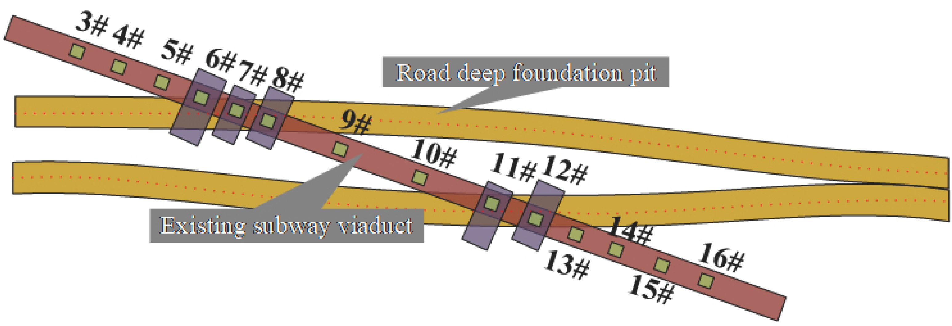
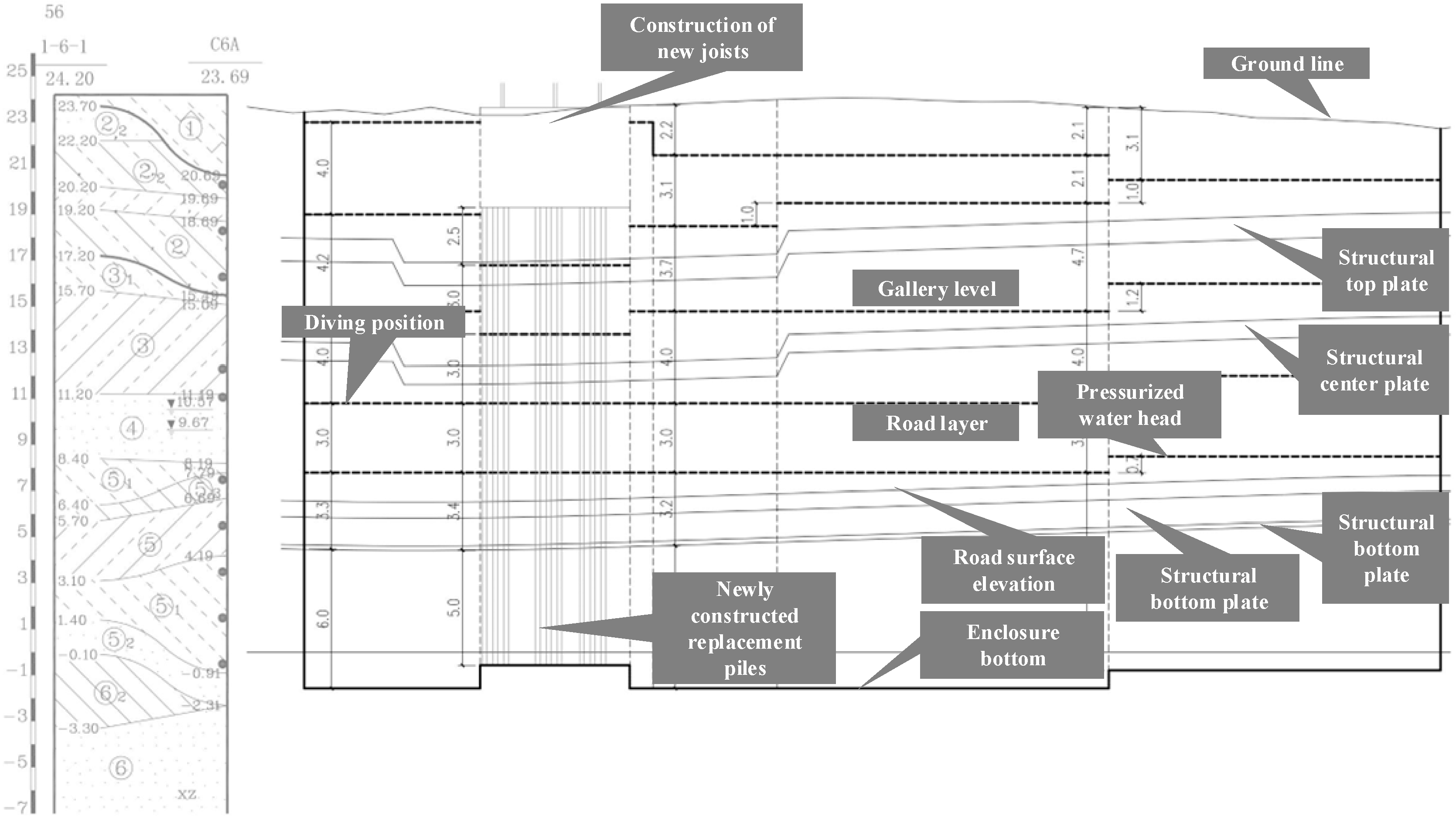
2.1. Project Overview

The road undercrossing a subway viaduct project utilizes pile foundation underpinning technology to create a deep foundation pit. This pit is divided into two sections, specifically the left and right sides. Figure 1 displays the plane diagram of the pile foundation underpinning project.
To ensure the uninterrupted operation of the current subway system during the construction period, it is necessary to reinforce the pile foundations of sections 6#, 7#, 8#, 11#, and 12# before excavating the deep foundation pit for the road. Additionally, the existing foundation must be deepened and widened to allow for the smooth passage of the new road’s deep foundation pit beneath the subway viaduct’s foundation. This will ensure the safe operation of both the bridge and subway structures. Piers 8# to 11# support a continuous beam spanning a total length of 40.5 m + 50 m + 40.5 m in the upper section of the subway viaduct. The other piers hold simple-supported beams. Table 1 displays the summary table of the piling foundation for the piers of the current subway viaduct. The piers that require underpinning for piling foundations are 6-1#, 6-2#, 7-1#, 7-2#, 8-1#, 8-2#, 11-1#, 11-2#, 12-1#, and 12-2#. Additionally, the piers near the road foundation pit that needs underpinning are 5-1#, 5-2#, 9#, 10#, 13-1#, and 13-2#. The remaining piers are numbered 3#, 4#, 14#, 15#, and 16#.
The schematic diagram of the underpinning structure is shown in Figure 2.
The engineering geological conditions are as follows, which is shown in Figure 3. The surface layer along the proposed road is generally an artificial accumulation layer ranging from 0.50 m to 3.00 m thick, and the soil quality is mainly chalky soil and a vegetal fill ① layer and miscellaneous fill ①1 layer. There are recent sedimentary layers along the proposed road, and the soil quality is mainly a ② layer of powdery clay, a ② layer of chalk, a ②1 layer of chalk, and a ②2 layer of fine sand. Below the recent sedimentary layer is the Quaternary sedimentary layer, which is mainly composed of clayey soil, chalk, and sandy soil interaction layer, with rounded gravel and pebble soil layer in local distribution. Specifically, it includes the following: powdery clay ③ layer, chalk ③1 layer, organic clay ③2 layer, fine sand and medium sand ④ layers, powdery clay ⑤ layer, chalk ⑤1 layer, fine sand, medium sand ⑤2 layers, clay ⑤3 layer and gravel ⑤4 layer, fine sand and medium sand ⑥ layers, powdery clay ⑥1 layer, clay ⑥2 layer.
The groundwater level investigation of the project is shown in Table 2.
The foundation hole requiring underpinning for the abutment is located outside the groundwater area. The lower slab of the road’s deep foundation hole is situated beneath the level of groundwater. Due to the high water head of the limited area and the presence of an existing subway viaduct, dewatering procedures cannot be implemented for the deep foundation pit of the road undercrossing. Therefore, it is necessary to implement appropriate water-stopping measures.

2.2. Monitoring Program

This article focuses on the engineering monitoring of the deformation of the bridge structure and the subway track structure within the range of subway viaduct sections 3# to 16#. The corresponding mileage for this range is from K14 + 282 m to K14 + 693 m. The bridge structure and track structure within the range of 5#, 6#, 7#, 8#, 9#, 10#, 11#, 12#, and 13# are the primary areas of focus for monitoring. If necessary, appropriate protective measures should be implemented. The project can be divided into four monitoring stages based on the construction steps. These stages include the construction of the retaining pile and underpinned pile, the excavation of the foundation pit with underpinned abutment, the construction of the underpinned abutment, the pile foundation underpinning, and the construction of the deep foundation pit for the road. The first three monitoring stages pertain to the piling foundation underpinning phase of the construction project, whereas the fourth monitoring stage corresponds to the foundation pit excavation phase of the building project. Pictures of the construction site are shown in Figure 4. Table 3 displays the deformation control values of the temporary retaining pile construction for a foundation pit with an underpinned abutment. Table 4 displays the deformation control parameters for the subway viaduct structure and track structure during the pile foundation underpinning. Table 5 displays the deformation control parameters for the subway viaduct structure and track structure during foundation pit construction. The allowable static geometric deviation of the track structure for the current subway route is displayed in Table 6.
Figure 5 displays the arrangement of measuring points on the current subway pier structure.
The track structure’s vertical displacement measuring point is positioned on the track, as depicted in Figure 6’s arrangement diagram. The current subway system in this project is comprised of two separate lines, namely the upper line and the lower line. Figure 7 displays the schematic diagram of the underground line.

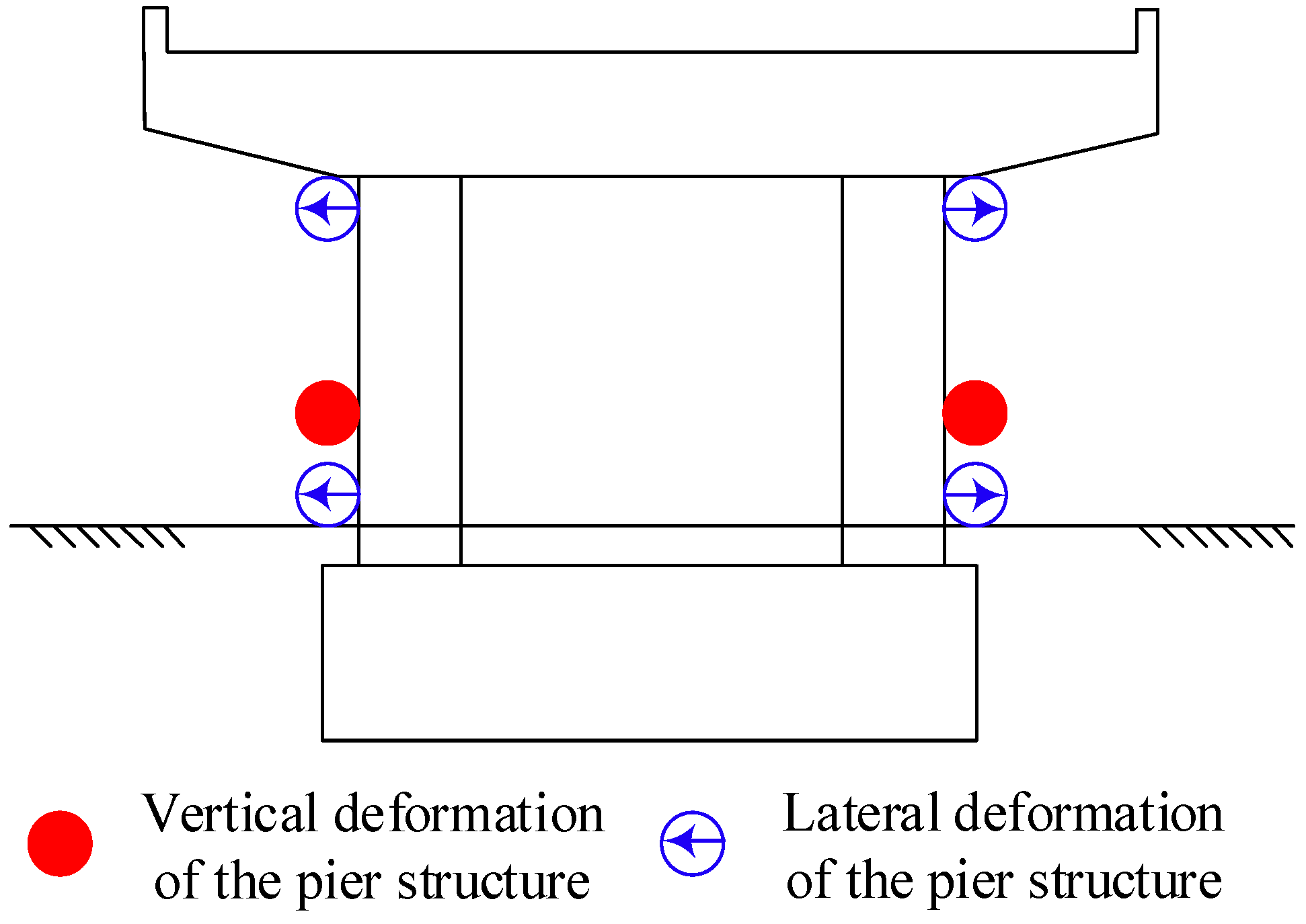
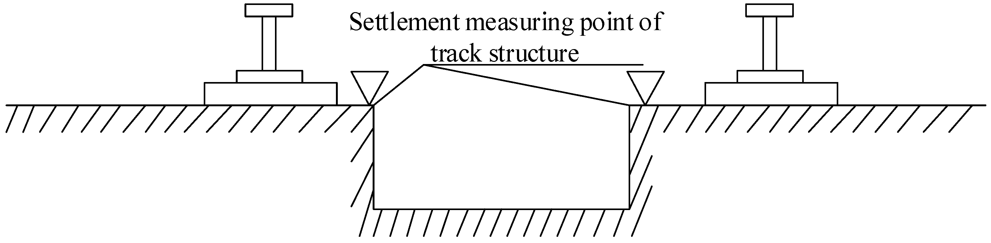
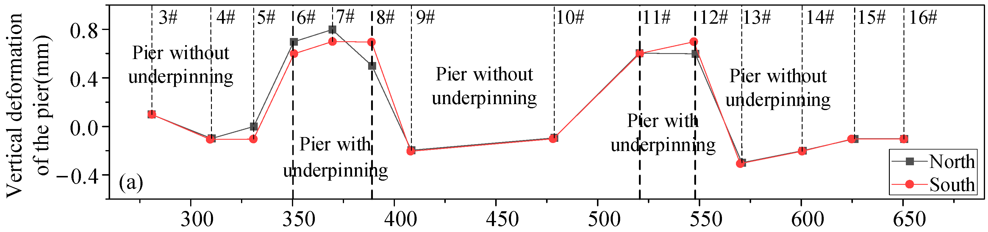
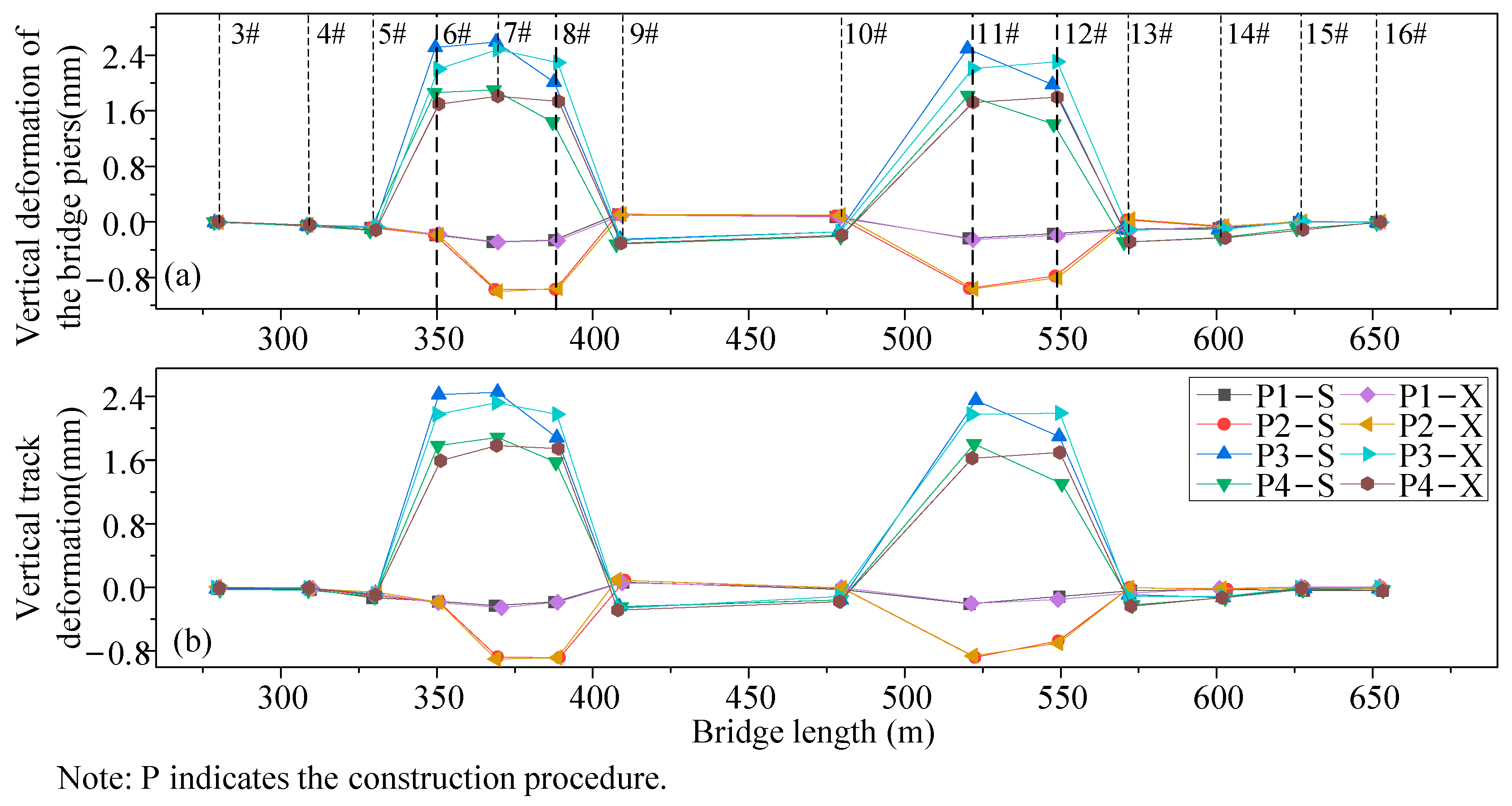
2.3. Analysis of Monitoring Results of Vertical Deformation of the Pier and Track

During the monitoring process, measuring points are strategically placed on 21 piers of the current subway viaduct. The resulting vertical deformation of the piers is seen in Figure 8a. The final vertical deformation number indicates that the pier’s vertical displacement is within the range of 3 mm. Points 6, 7, 8, 11, and 12 of the piers at the pile foundation underpinning exhibit a vertical uplift deformation. This is primarily due to the jacking operation causing a larger amount of vertical uplift than the settlement during the late pile cutting. Consequently, the piers continue to experience vertical uplift deformation, with a maximum value of 0.8 mm observed on the north side of Point 7 at the pile foundation underpinning. The ultimate deformation observed on the southern side of measuring Point 5, as well as Points 9, 10, and 13 near the road foundation pit, is the settlement. In this context, settlement deformation [26] refers to the phenomenon of displacement or deformation of an object in the vertical direction, usually manifested as a reduction in elevation. The highest settlement value recorded is −0.3 mm, which is observed at measuring Point 13 near the road foundation pit, specifically at the bridge pier. The ultimate deformation observed at measuring Points 4, 14, 15, and 16 of the other pier is settlement deformation. However, the ultimate deformation observed at measuring Point 3 of the pier is vertical uplift deformation, primarily resulting from manual measurement mistakes. During the underpinning stage of the pile foundation, the vertical deformation of the pier at the underpinning point is measured to be an average of 0.65 mm, indicating a vertical uplift deformation. The mean value of the ultimate vertical displacement at the pier measuring site adjacent to the road foundation pit is −0.17 mm, indicating settlement deformation. The mean value of the ultimate vertical displacement of the remaining piers is −0.08 mm, indicating settlement deformation. It can be seen that the influence of pile foundation underpinning on the vertical deformation of pier measuring points of the existing subway viaduct is as follows: pier measuring points at pile foundation underpinning > pier measuring points near the road foundation pit > other pier measuring points.
Figure 8b displays the ultimate vertical displacement of the current subway tracks 1 and 2 on the top line, as well as Track 3 and Track 4 on the lower line, as determined from the track vertical deformation monitoring outcomes. Based on the figure, during the pile foundation underpinning stage, the vertical deformation curves of Track 1 and Track 2 on the upper subway line align, while the vertical deformation curves of Track 3 and Track 4 on the lower line exhibit a similar pattern. Additionally, the vertical deformation values for all tracks fall within the range of 3 mm. The vertical deformation trend of the track at the upper and lower lines is essentially identical. The vertical deformation of the upper track, specifically at Piers 6#, 7#, 8#, 11#, and 12#, is characterized by uplift. This is due to the vertical uplift deformation of the piers caused by the jacking operation at this location, resulting in the uplift deformation of the track structure. The greatest vertical deformation of the rail structure takes place at Pier 7#, where the piling foundation is reinforced, aligning with the location of the most vertical distortion. The vertical deformation of the pier and track structure of the current subway viaduct bridge are directly related. This means that the vertical deformation of the pier may accurately represent the vertical deformation of the upper track structure.
Five representative bridge piers were chosen for vertical deformation measurements due to their abundance of measurement locations. QD5-2 and QD13-2 are located in close proximity to the road foundation pit. QD10 is situated near the road foundation pit and features a continuous-beam upper-bridge structure. QD7-2 and QD12-2 are positioned at the location of the pile foundation underpinning. Figure 9a displays the time history diagram of vertical deformation at the measurement points of a typical pier. The vertical deformation of QD5-2, QD10, and QD13-2 exhibits a consistent downward tendency throughout the entire process of piling foundation underpinning. However, the settlement range is minimal, with vertical deformation ranging from 0 mm to 0.5 mm. The vertical displacement of QD7-2 and QD12-2 exhibited a declining pattern throughout the construction of the pile foundation, excavation of the foundation pit, and cutting of the piles. The rate of vertical deformation is gradual during pile foundation construction, whereas it is comparatively rapid during foundation pit excavation and pile cutting. Based on the analysis, it can be inferred that the construction of the pile foundation has minimal impact on the vertical deformation of the pier at the location where the pile foundation is supported. However, the excavation of the abutment foundation pit and the cutting of the pile have a slightly more significant effect. The vertical deformation of pier measuring points QD7-2 and QD12-2, located at the position of the pile foundation underpinning, exhibited an upward trend during the jacking operation. Eventually, the deformation stabilized. This can be attributed to the influence of the jacking action exerted by the jacks during the operation. The stabilization indicates the completion of the jacking operation and the commencement of the static observation period. Upon comparison, it is evident that there is a significant disparity in vertical deformation between the pier located at the pile foundation underpinning location and the pier adjacent to the road foundation pit during the jacking operation. The vertical deformation of the former had experienced the most substantial alteration with the greatest velocity during the jacking operation. Hence, it is crucial to prioritize the vertical deformation of the pier at the location of the pile foundation underpinning while performing the jacking operation.
Selection of monitoring data from the downstream track vertical deformation measurement point directly above the bridge abutment. A time history diagram illustrating the vertical deformation at typical measurement points is depicted in Figure 9b. There is a minor degree of settlement deformation observed at GC5-2, GC10, and GC13-2 during the pile foundation underpinning stage. Settlement deformation is observed in the vertical displacement of GC7-2 and GC12-2 during the construction of pile foundations, excavation of foundation pits for abutments, and cutting of piles. Additionally, upward uplift deformation occurs in the track structure during jacking operations. This deformation corresponds to the vertical displacement trend of bridge piers due to pile foundation underpinning and is caused by the jacking action. During the pile-cutting process, the vertical deformation measuring point located directly above the bridge pier at the position of the pile foundation underpinning shows settlement deformation. However, there is no notable change in the vertical deformation of the track measuring point located directly above the bridge pier near the road foundation pit. This suggests that the process of cutting the pile has a more significant effect on the vertical displacement of the track directly above the pier at the pile foundation underpinning location compared with the track directly above the pier near the road foundation pit.

2.4. Analysis of Monitoring Results of Transverse Deformation of the Pier and Track

Figure 10a displays the transverse deformation of the metro viaduct pier end at the site. The final transverse deformation value of each pier of the existing subway viaduct is seen to be within the specified control value of 3 mm. The pier test point with the pile foundation underpinning experiences a maximum transverse deformation of −0.5 mm. This distortion occurs in the north of Pier Test Point 7 and is sloped towards the inside of the excavation. The final transverse deformation of the pier at the road foundation pit and other measuring places has a maximum value of −0.1 mm. The deformation is sloped toward the inside of the excavation. The mean transverse deformation of the pier with the pile foundation underpinning is −0.37 mm, while the mean transverse deformation of the pier near the road foundation pit and other pier is −0.05 mm. It can be concluded that the influence of pile foundation underpinning on the transverse deformation of the pier measurement points of the existing subway viaduct bridge is as follows: the pier measurement points at the position of pile foundation underpinning > the pier measurement points at the adjacent road foundation pit and other pier measurement points.
The monitoring data for the ultimate lateral deformation of the track structure during the pile foundation underpinning stage are chosen. The resulting lateral deformation of the underground track structure is illustrated in Figure 10b. Based on the figure, the transverse deformation values of all measurement places in the track structure are below the control value of 3 mm. The ultimate transverse deformation at the measuring site of the track structure reaches a maximum value of −0.5 mm. This maximum deformation occurs at Pier 7# and Pier 11# and is in line with the maximum transverse deformation of the pier. The transverse deformation trend of the pier is indicative of the transverse deformation trend of the track. The influence of pile foundation underpinning on the transverse deformation of the existing subway track structure is as follows: the corresponding track structure above the pier with the pile foundation underpinning > the corresponding track structure above the pier near the road foundation pit and other piers.

3. Effect of Pit Construction on the Deformation of Existing Structures

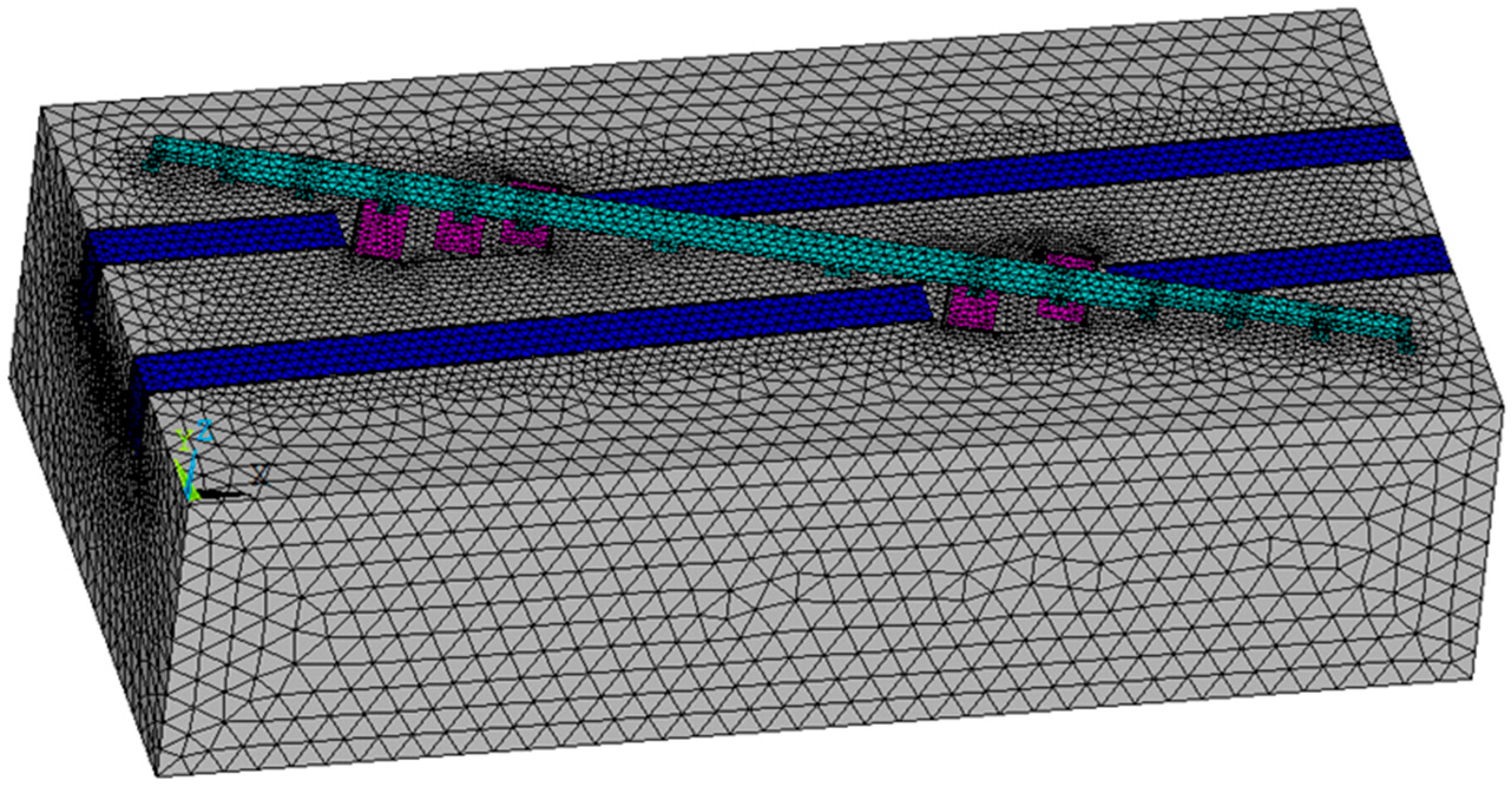
3.1. Finite-Element Modeling

To assess the impact of an instance of road-deep foundation pit building on the existing subway viaduct bridge and track structure, a finite element model of the construction process is created. The numerical model includes a shared node connecting the surrounding pile and the soil, as well as a contact element linking the bridge pile and the soil. The numerical model’s boundary conditions consider the surface as the free boundary, with normal constraints applied around the model and at the bottom. The dimensions of the model are 390 m in length, 185 m in width, and 100 m in height. The material specifications can be found in Table 7 and Table 8. To simplify the model calculation, certain parts of the deep foundation pit project for the new road are simplified. The remaining sections of the project, except for the initial ground construction and the removal of the temporary road surface system, are constructed using the paving method. The construction process for these sections is the same as that for the pile foundation underpinning section and the adjacent subway bridge pile section. Consequently, the modeling process does not take into account the installation and removal of the military beam temporary pavement system.
The model simulation employs the equivalent stiffness method to equate the retaining piles with diaphragm walls. The pile foundation supporting the section pit retaining piles can be considered equivalent to a 768 mm diaphragm wall with a length of 16.5 m. Similarly, the pile foundation supporting the section pit adjacent to the subway can be considered equivalent to a 768 mm diaphragm wall with a length of 24.2 m. The road’s deep foundation pit engineering model exclusively utilizes the Solid45 material. In Ansys, the calculating model is partitioned into 1,029,972 elements and 175,323 nodes. Figure 11 displays the comprehensive 3D finite element model.
The construction process is comprised of six steps. Firstly, the deep foundation pit of the road in the pile foundation underpinning section is excavated until reaching the bottom plate. Secondly, the deep foundation pit of the road in the neighboring subway section and the remaining section are excavated to a depth of 7.0 m. Thirdly, the deep foundation pit of the road is excavated to a depth of 4.2 m. Fourthly, the deep foundation pit of the road is excavated to a depth of 3.0 m. Fifthly, the deep foundation pit of the road is excavated down to the bottom plate. The entire building procedure utilizes the “kill” element to replicate the excavation of the road’s deep foundation trench.

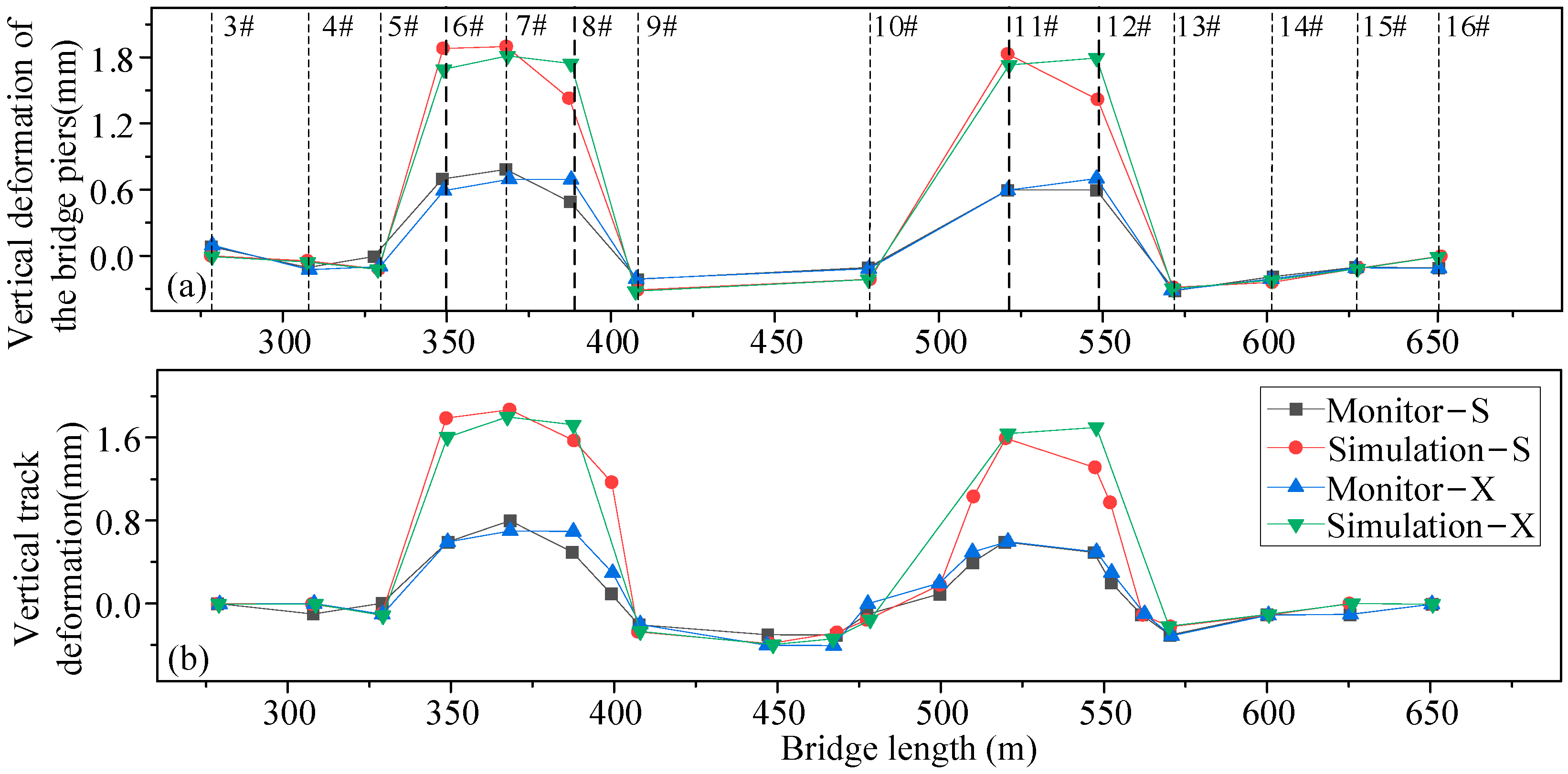
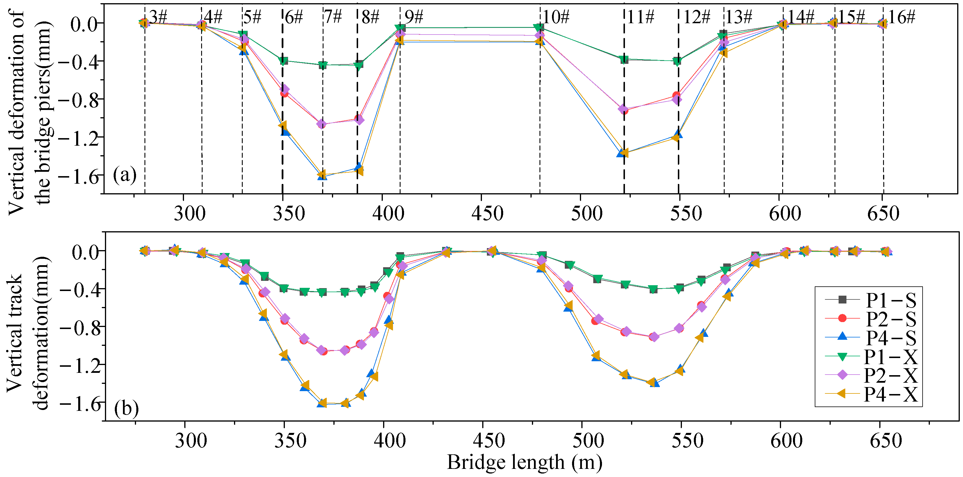
3.2. Comparison and Analysis of Monitoring Results and Simulation Results of Bridge Piers and Track Structures

(1) Comparative analysis of vertical deformation
The numerical simulation results in Figure 12a display the final vertical deformation of the bridge pier during the pile foundation underpinning, which is compared to the actual vertical deformation observed in the field. The observed maximum vertical uplift deformation value of the pier in the field is 0.8 mm. The calculated maximum vertical uplift deformation value of the pier through numerical simulation is 1.904 mm. This occurs specifically in Pier 7# of the pier in the pile foundation underpinning. The numerical simulation of the vertical deformation value of the abutment is approximately 1.4 times greater than the vertical deformation value observed through site monitoring. The reason for this is that the field jacking operation involves graded loading and displacement control as a criterion. In the process of jacking and cutting the piles, displacement is monitored and adjusted in real-time. However, this process cannot be accurately represented in numerical simulations. The numerical simulation results for the piers at both ends of the bridge show a slight deviation from the deformation trend observed on-site. However, the vertical deformation values for both are minimal, fluctuating within the range of ±0.3 mm. These discrepancies can be attributed to measurement errors in the instruments used.
Figure 12b illustrates the comparison of the final vertical deformation obtained from numerical simulation with the final vertical deformation of the track structure in the upper and lower lines of the existing subway, as well as the final vertical deformation observed in the actual monitoring. The vertical deformation trend observed in the numerical simulation closely matches that of the field monitoring. The deformation occurs at the same location, specifically directly above Pier 7#, where the pile foundation is providing support. The vertical deformation of the bridge track differs between the numerical simulation results and field monitoring data at both ends. This discrepancy is due to the minimal impact of the pile foundation underpinning construction on the structure of the bridge track at these ends, resulting in a small absolute value of vertical deformation. However, the vertical displacement of the track structure is significantly influenced by the dynamic load of the subway train at this time. The model calculation of the train load is based on static load considerations, which leads to a larger influence on the track structure at the two ends of the bridge region. Hence, the simulation outcomes for vertical deformation at both ends of the bridge diverge from the on-site monitoring data. The model calculations show that the vertical deformation of the track directly above the piers, at the location of the pile foundation underpinning, is greater than the deformation observed in the monitoring data. This discrepancy can be attributed to the fact that in the actual pile foundation underpinning the project, the jacking force is applied gradually, and displacement is used as a control criterion. Additionally, the vertical deformation of the track is continuously monitored and controlled in real-time by the ground support system during the jacking process. These real-time control measures cannot be replicated in the numerical simulation. However, it should be noted that the model’s calculations for the vertical deformation of the track above the piers with pile foundation underpinning are not accurate. Still, the model’s calculations of vertical deformation and the measurements of vertical deformation from the monitoring data at the abutment above the swapping location do not go over the limit that was set. Therefore, it is safe to continue operating the existing subway.
Based on simulation results and monitoring data, Figure 13a shows how Pier 7-2#‘s vertical deformation changed over time when it had a pile foundation underpinning it. The upward deformation of the bridge pier with pile foundation underpinning is a result of the lifting action exerted by jacks during the jacking operation. During the first stage of pile foundation underpinning, the deformation trend shown by the construction monitoring data and the numerical simulation results of the piers match up. During the intermediate stage of pile foundation underpinning, the primary construction activity is jacking. At this stage, the bridge pier experiences significant upward and vertical deformation. The numerical simulation results also show larger vertical deformations without any smooth periods. The discrepancy between the numerical simulation results and the field monitoring data arises from the fact that the jacking operation involves dynamic changes and displacements, which cannot be precisely controlled in the numerical simulation. The smooth period of the jacking operation in the actual construction process refers to the calm observation period that follows the jacking operation. During this period, the complex interaction force between the pile and soil ensures that the vertical deformation of the abutment remains smooth. However, this process cannot be simulated in numerical simulations. During the advanced stage of pile foundation underpinning, the primary focus of construction is on the operation of cutting the piles. On-site monitoring of pile cutting is a dynamic process that involves continuous changes. Numerical simulation can only provide results after the pile cutting has been completed, specifically related to settlement deformation.
For the underpinning of the pile foundation, we focused on analyzing the track structure directly above Pier 7. We compared and analyzed the field monitoring data with the time-range diagrams of the numerical simulation calculation results, as shown in Figure 13b. The vertical deformation trend of the simulated calculation for the lower line track structure closely matches that of the on-site monitoring data. The numerical simulation results of the vertical deformation of the track structure during the construction of the buttress piles and enclosure piles were smaller than the field monitoring data. This discrepancy arises because the simulation only considers the train load as a static load while, in reality, the track is subjected to the dynamic load of the subway train during the construction process. Settlement deformation was observed in both the numerical simulation results of the track structure and the on-site monitoring data during the excavation of the abutment underpinning the foundation pit and the underpinning of the abutment. During the jacking operation, the vertical deformation of the track structure is more pronounced. At this stage, the deformation trend observed in the construction monitoring and numerical simulation of the track structure is more aligned. However, the numerical simulation shows a larger vertical deformation and lacks a period of smoothness. This is due to the dynamic nature of the jacking operation process, which involves a period of calm observation after the operation in actual construction. This period cannot be accurately represented in numerical simulations. During pile cutting, the vertical deformation of the track structure observed in numerical simulation and on-site monitoring shows a consistent trend, with both indicating settlement deformation.
(2) Comparative examination of lateral deformation
Figure 13a displays the final transverse deformation comparison of the existing subway viaduct piers. The numerical simulation and monitoring data indicate that the maximum transverse deformations of the pier are −1.620 mm and −0.5 mm. These deformations primarily occurred in the pile foundation underpinning at Pier 7. The direction of the deformation is biased towards the inner side of the excavation. It can be seen that the numerical simulation and monitoring data of the abutment transverse deformation trend are basically the same, but the simulation results of the transverse deformation are greater than the monitoring data of the transverse deformation. This is consistent with the previous section and will not be repeated here.
Figure 14b displays the ultimate lateral distortion of the current subway track structure. The transverse deformation of the subway track structure reaches a maximum value of −1.612 mm in the simulation data and −0.5 mm in the monitoring data. This deformation occurs directly above Pier 7-1# at the pile foundation underpinning, specifically in the upper line track position. The deformation is biased towards the inner side of the excavation. The transverse deformation trend observed in the numerical simulation and monitoring data are similar. However, the track structure in the simulation results experiences greater transverse deformation compared with the track structure in the monitoring data. The reason for this has already been explained in the previous section and will not be reiterated here.
It was found that the numerical simulation results tend to overestimate the deformation when piers and tracks in existing subway viaducts are deformed vertically and transversely. This was seen when monitoring data and numerical simulation results were compared. However, the overall trend of deformation observed in the monitoring data aligns with the numerical simulation results. Therefore, it is reliable to utilize numerical simulation for studying the deformation patterns of existing subway viaducts during the pile foundation underpinning and pit excavation works.

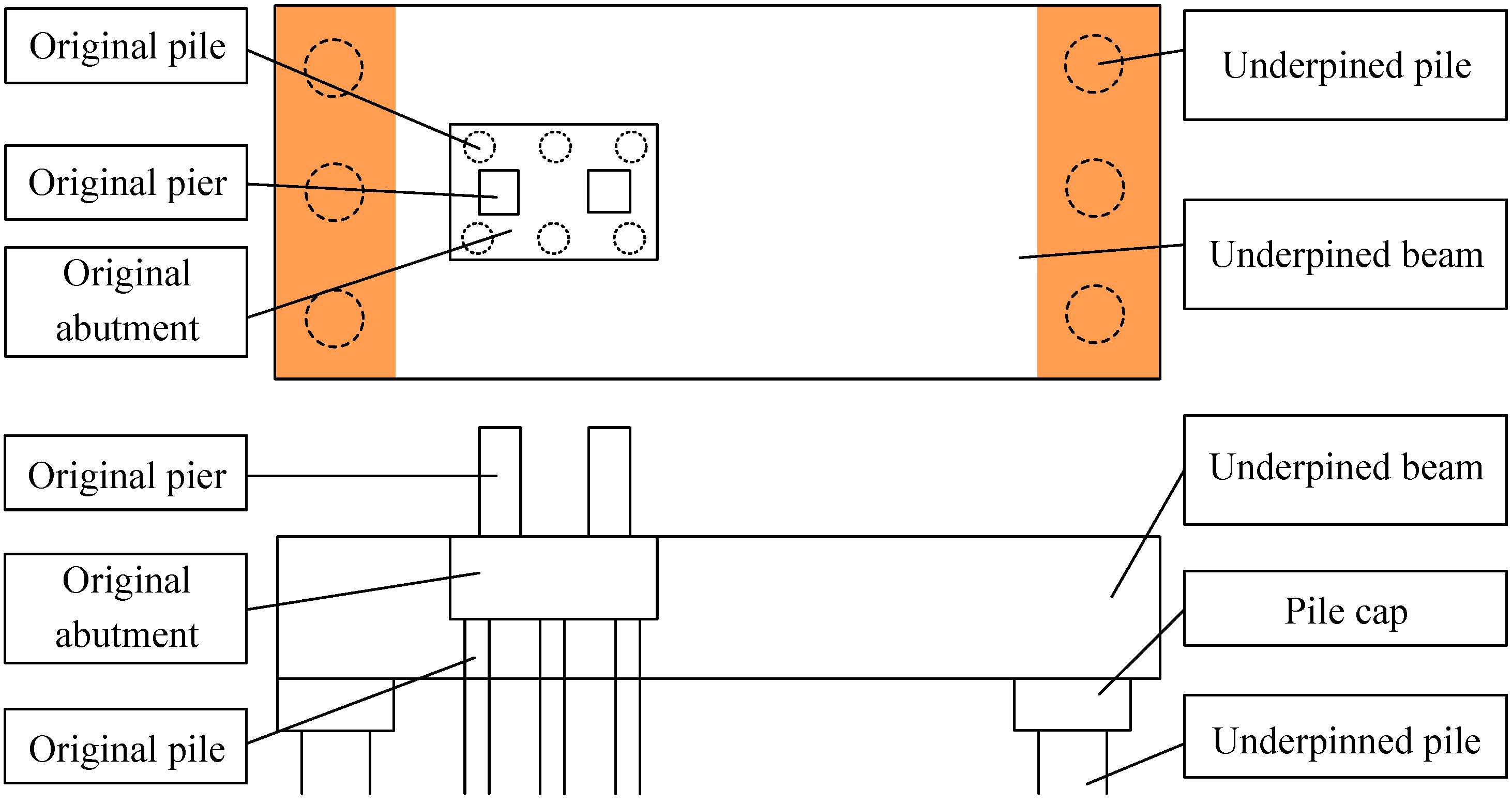
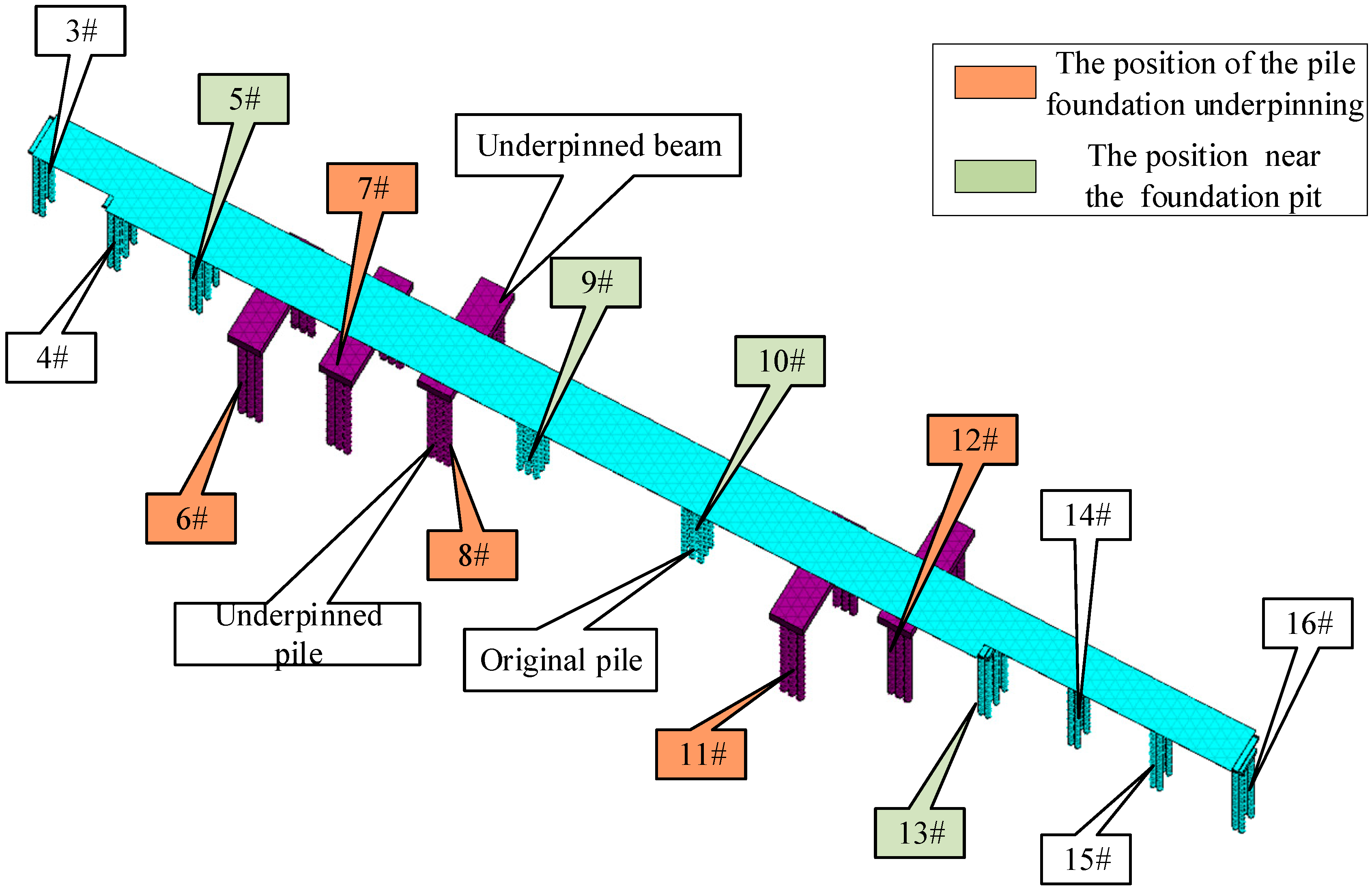
4. Impact of Pile Foundations Underpinning Construction on Existing Structures

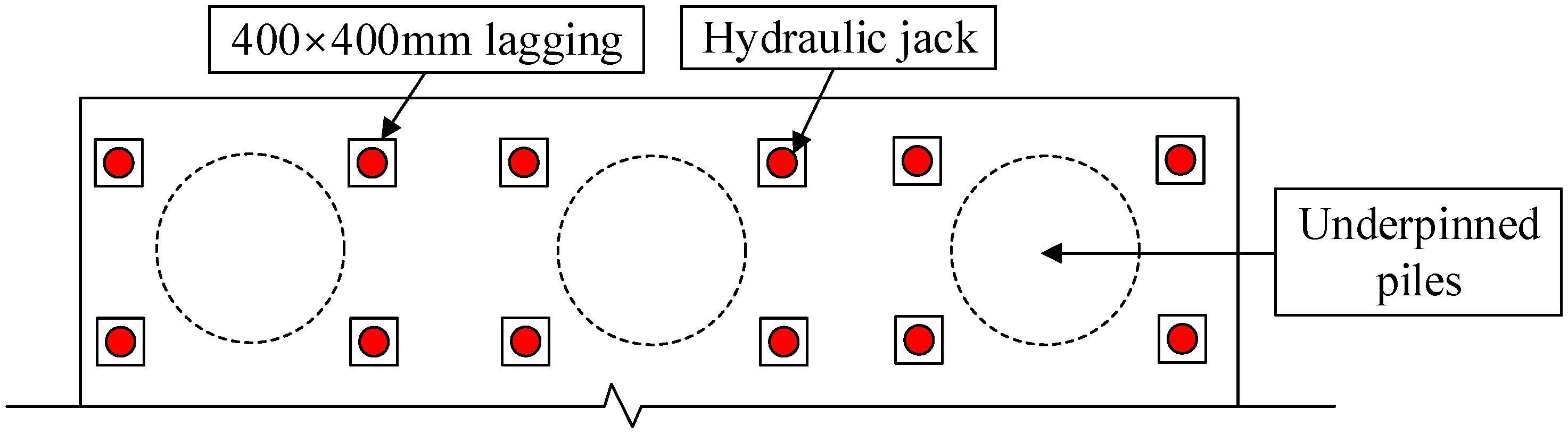
4.1. Finite Element Modeling

During the construction of the pile foundation underpinning, the upper subway continues to operate normally. However, due to the strict deformation requirements of the existing structure, active underpinning is used. This involves designing and calculating the jacking force of the piers and columns. Upon calculation, the maximum design load of the single pile of the underpinning pile is 11,400 kN, that is, about 1140 t. The hydraulic jack’s tonnage should exceed the load it bears by approximately 30%. Thus, this project suggests using four jacks to replace the single pile simultaneously. Each jack should have a tonnage greater than 370.5 t. Because multiple jacks will be used simultaneously for jacking, there may be an uneven load distribution. Therefore, it is necessary to have a sufficient margin of jacking force. Hence, this project proposes using four 400-ton jacks to jack the single pile. Additionally, square pads with a side length of 400 mm are recommended for this purpose. When using a jack, Figure 15 displays the arrangement and design of the jacks.
Based on the jack’s plan layout, a finite element model of the pile foundation underpinning construction was created. Analyze the deformation impact of the underpinning project on the existing subway’s viaduct structure and track structure to verify the feasibility of the design parameters and jack layout design. (1) The current subway is only designed for normal use and does not take into account earthquake or human defense conditions during tunnel excavation and construction. (2) The existing subway structure is assumed to behave like a linear elastic material. (3) It is assumed that there is proper coordination of deformation between the pit structure, the existing subway structure, and the surrounding soil. (4) The construction is carried out under well-controlled conditions.
The parameter values are comparable to those in Section 3. The soil’s physical-mechanical parameters are presented in Table 7, while the structural physical-mechanical parameters are displayed in Table 8. Given the impact of spatial factors in construction and the positional relationship between the foundation pit’s abutment underpinning and the existing subway viaduct, it has been concluded that the current model’s dimensions are 390 m × 185 m × 100 m. Given the strong correlation between the deformation of the track structure and the deformation of the bridge girder, a specific cross-section is chosen to investigate the deformation of the subway track structure. The numerical model includes a shared node between the surrounding pile and the soil, as well as a contact element between the bridge pile and the soil. To streamline the model calculation, the current project is partially simplified. The numerical model’s boundary condition designates the ground surface (the uppermost surface of the model) as the free boundary. Normal constraints are applied around the model and at the bottom. All pile foundation underpinning construction models utilize the Solid45 element. In Ansys, the calculation model is comprised of a total of 476,275 elements and 82,954 nodes. The 3D finite element model closely resembles the schematic diagram presented in Section 3. Additionally, Figure 16 illustrates the finite element model of the subway viaduct structure. The construction process is segmented into four distinct stages: The construction involves the use of retaining piles and pile foundation underpinning. A “kill” element is employed to simulate the excavation of the pit. Additionally, the replacement piles under the replacement abutment are subjected to an upward design top force to simulate the jacking operation. Utilize the “kill” element to simulate the process of cutting piles.

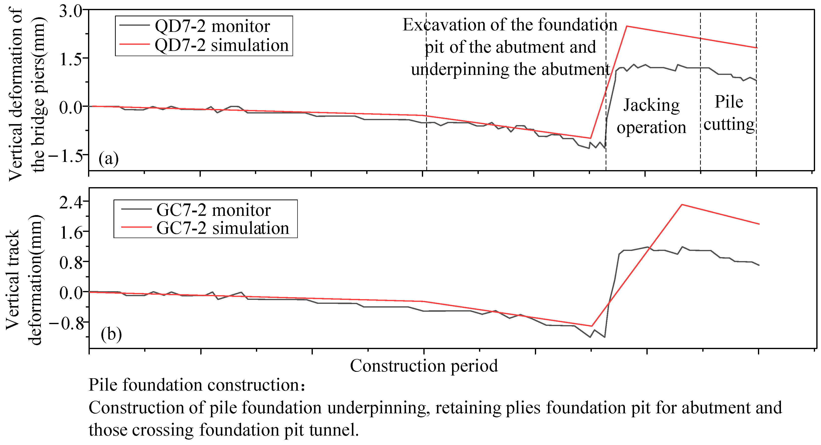
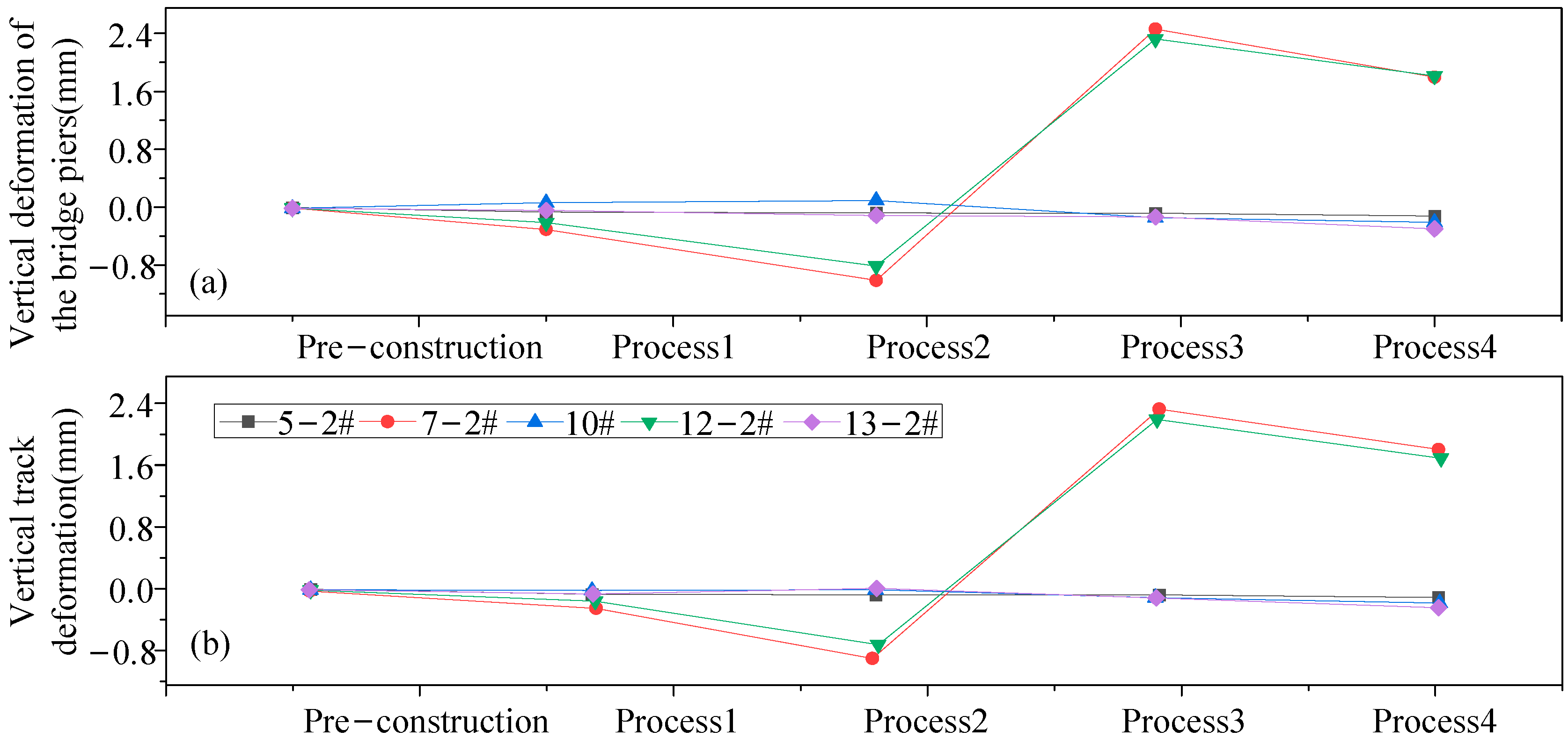
4.2. Examining the Impact of Pile Foundation Underpinning on the Deformation of Bridge Piers and Tracks

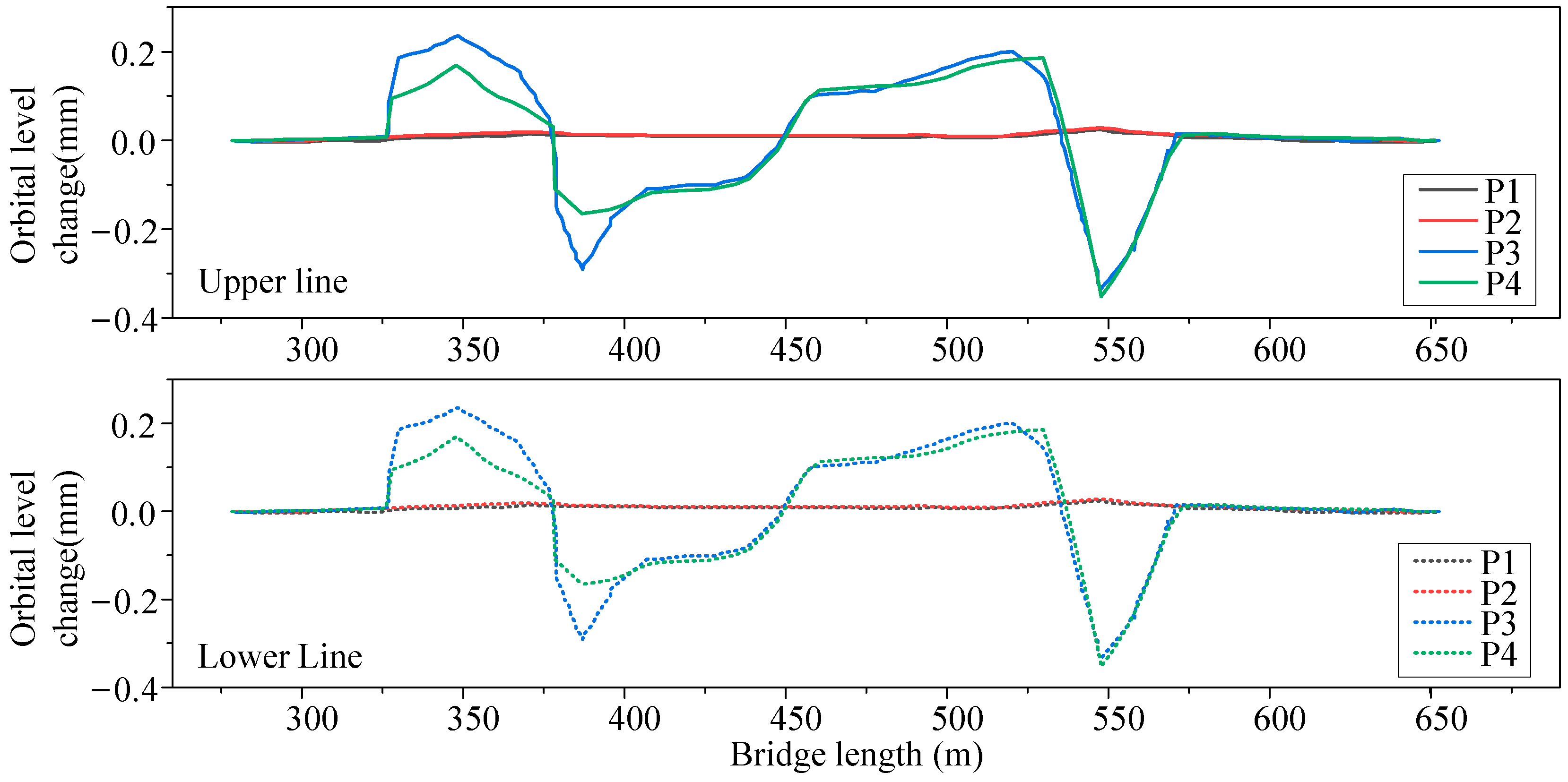
4.2.1. The Law Governing the Vertical Deformation of a Sub-Bridge Structure

For each bridge pier, select a representative point and illustrate the vertical deformation of the abutment’s representative point during each step shown in Figure 17a. Additionally, depict the vertical deformation of the subway’s upper and lower track structures during each step of the pile foundation underpinning stage in Figure 17b. Process 1 (P1) and Process 2 (P2) show a vertical deformation trend in the piers and track, with a small settlement deformation. The maximum vertical settlement values for the piers and track are −0.999 mm and 0.892 mm, respectively. These occur at Piers 7–2 in the pile foundation underpinning. In Process 3 (P3), Piers 6 #, 7 #, 8 #, 11 #, and 12 # in the pile foundation underpinning experience noticeable uplift deformation due to the jacking effect. The maximum vertical deformation values of piers and tracks are 2.597 mm and 2.473 mm, respectively. These deformations occur at Pier 7-1# in the pile foundation underpinning. In Process 4 (P4), the piers numbered 6#, 7#, 8#, 11#, and 12# in the pile foundation underpinning experienced larger jacking deformation compared to settlement deformation after the piles were cut. As a result, these piers still exhibited cumulative vertical uplift deformation. However, settlement deformation still occurred at the piers in the pile foundation underpinning. The maximum vertical deformation values observed were 1.904 mm and 1.877 mm, which were recorded at Pier 7-1# in the pile foundation underpinning. During the pile foundation underpinning stage, Piers 6, 7, 8, 11, and 12 deform vertically 64% to 88% more than Piers 5, 9, 10, and 13 at nearby road pits. Additionally, the deformation of Piers 6#, 7#, 8#, 11#, and 12# is 91% to 96% greater than the average deformation of Piers 3#, 4#, 14#, 15#, and 16#.
Based on the analysis conducted, it is evident that the vertical deformation of the existing piers during the underpinning of the pile foundation follows the following order: piers with pile replacement > piers adjacent to the road pit > other piers. Additionally, the maximum vertical deformation of the piers is observed at Pier 7# during the underpinning of the pile foundation. Furthermore, the jacking operation, which involved raising the pile foundation using a jack, resulted in vertical uplift deformation at the piers. This deformation also caused vertical settlement of the abutment during the rest of the underpinning process.
The track structure experiences its greatest vertical deformation directly above the piers in the pile foundation underpinning. The jacking operation has the most significant impact on the vertical deformation of the track structure. Upon comparison with the vertical deformation of the piers, it is evident that the maximum vertical deformation of the track structure is slightly less than the maximum vertical deformation of the pier structure. The vertical deformation pattern of the track structure on the upward and downward lines closely resembles that of the bridge piers. The vertical deformation of the bridge piers can serve as an indicator of the vertical deformation of the track structure above.
The vertical deformation values of Piers 5-2#, 7-2#, 10#, 12-2#, and 13-2# and their corresponding upper track structures were extracted at each stage of the pile foundation underpinning process. A time-history diagram of the vertical deformation of a typical pier was then created, as depicted in Figure 18. Piers 7-2# and 12-2# are examples of piers where the pile foundation has been substituted. Piers 5-2#, 10#, and 13-2# are located next to the foundation pit of the road. The bridge structure above Pier 10# is a continuous beam. Throughout the entire process of pile foundation underpinning, Piers 5-2#, 10#, and 13-2# and the track adjacent to the foundation pit of the road exhibit a consistent trend of settlement. The vertical deformation is minimal, with an absolute value ranging from 0 mm to 0.5 mm. Piers 7-2# and 12-2# of the pile foundation underpinning exhibited a consistent decrease in Process 1, Process 2, and Process 4. Process 3 is experiencing a positive trend. There is a significant disparity in vertical deformation between piers located at the pile foundation underpinning and those near the road foundation pit following the jacking operation, which is Operation 3. The differential settlement between adjacent piers serves as a crucial indicator for assessing the safety of the subway viaduct structure. The numerical simulation results indicate that the largest settlement difference between neighboring piers is 2.595 mm. This occurs specifically between Pier 5-1# near the road foundation pit and Pier 6-1# at the pile foundation underpinning after the jacking operation. This is primarily due to the upward displacement caused by the jacking effect of the jacks on the piers of the pile foundation underpinning. The amount of displacement between adjacent piers is relatively consistent. However, the vertical deformation of the piers near the road foundation pit is not influenced by the jacking action, resulting in minimal vertical deformation. Hence, the greatest disparity in settlement arises between the neighboring piers at the pile foundation supporting the underpinning and the piers at the adjacent road foundation excavation.
Based on the analysis above, it is evident that the stage of pile foundation underpinning at the abutment has the greatest impact on the vertical deformation of the track above. Additionally, the jacking operation on the pile foundation underpinning the abutment causes the largest vertical deformation. However, the impact on vertical deformation from the pit retaining pile and underpinned pile construction on the pile foundation underpinning at the abutment is negligible. Of all the activities, the settlement of the track structure is most noticeable when excavating the abutment underpinning the foundation pit and cutting piles. Additionally, the track experiences significant upward bulging deformation during jacking operations.

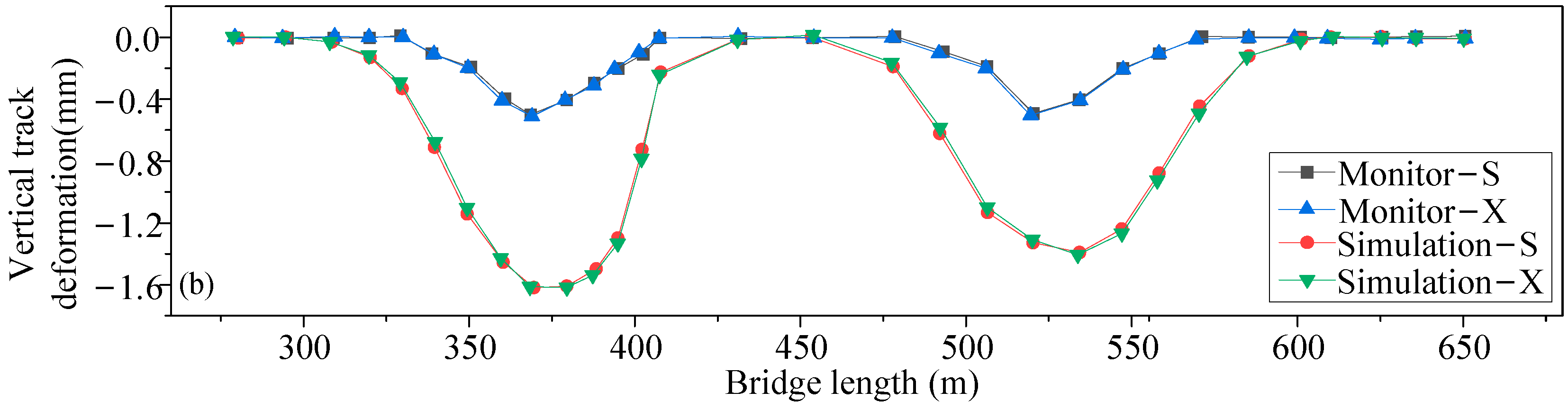
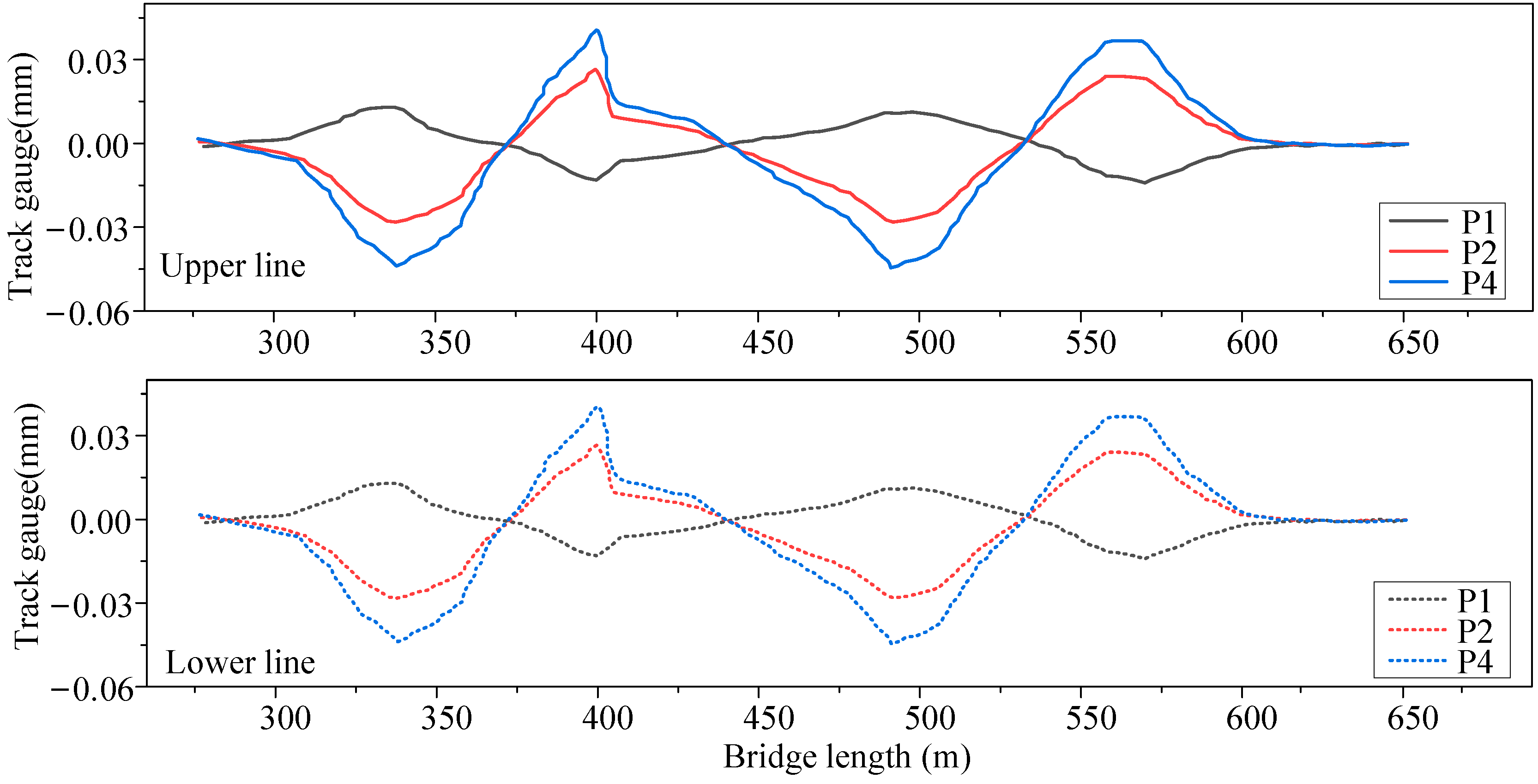
4.2.2. Law Governing the Transverse Deformation of Under-Bridge Structures

The transverse deformation data of specific points on piers and tracks were collected. The transverse deformation of subway viaduct piers and tracks was measured during each stage of the pile foundation underpinning process. This information is illustrated in Figure 19. During the pile foundation replacement phase, the existing pier and track experience an increase in absolute transverse deformation, with the deformation direction leaning towards the interior of the excavation. In Process 1, the existing pier and track experience a maximum transverse deformation of 0.442 mm and 0.433 mm, respectively. The former incident takes place at Pier 7-1# of the pile foundation underpinning, while the latter incident occurs at the track position of the down-running line directly above Piers 7-2# and 8-2# of the pile foundation underpinning. In Process 2, the maximum lateral displacement of the pier and track is 1.070 mm and 1.049 mm, respectively. This displacement is observed at Pier 7-1# in the pile foundation underpinning area. During Process 4, the maximum transverse deformation of the existing pier and track was measured to be 1.620 mm and 1.612 mm, respectively. This deformation was observed at Pier 7-1#, specifically at the location of the pile foundation underpinning. The average lateral displacement of Piers 6#, 7#, 8#, 11#, and 12# due to pile foundation underpinning is 60%~80% greater than that of Piers 5#, 9#, 10#, and 13# near the road foundation pit, and 93%~98% greater than that of Piers 3#, 4#, 14#, 15#, and 16#.
Based on the aforementioned analysis, it is evident that the transverse deformation of existing piers during the pile foundation underpinning occurs in the following sequence: piers at pile buttressing > piers at adjacent roadway pits > other piers. The transverse deformation direction is biased towards the inside of the excavation. The maximum transverse deformation value of the pile foundation underpinning occurred at Pier 7. The transverse deformation pattern of the subway upper and lower line track structure is essentially identical to the transverse deformation pattern of the abutment. The transverse deformation of the abutment can serve as an indicator of the transverse deformation of the track structure above it. The highest transverse deformation of the subway track structure during each stage of the pile foundation underpinning occurs directly above the bridge pier at the pile foundation underpinning. The maximum transverse deformation of the track structure is slightly lower than the maximum transverse deformation of the corresponding bridge pier beneath it.
Vertical and lateral deformation of the track structure will result in alterations to the track geometry. Hence, based on the identical finite element model, the track’s geometric position is further examined, encompassing variations in height, level, and gauge both before and after. As per the control indexes outlined in the Enterprise Standard Technical Standard Work Maintenance Rules of Beijing Subway Operation Co., Ltd., the height deviation refers to the highest vector value measured using a 10 m string to assess the geometric position of the subway track. The numerical simulation calculation model extracts the height change of each track within a range of 10 m in chord length. Table 9 displays the height deviation values before and after each process track during the pile foundation underpinning stage.
The vertical deformation values of Track 1 and Track 2 in the upper line, as well as Track 3 and Track 4 in the lower line, are extracted for each process. The horizontal change of the subway track is determined by calculating the difference in vertical deformation between the two tracks in the same cross-section. Figure 20 displays the horizontal displacement of each process track. It reveals that the upper line’s maximum subway track level deviation is −0.356 mm, with Track 2 experiencing slightly more vertical deformation than Track 1. Similarly, the lower ine’s maximum subway track level deviation is −0.367 mm, with Track 4 having slightly more vertical deformation than Track 3.
The transverse deformation values of Track 1 and Track 2 on the upper line, as well as Track 3 and Track 4 on the lower line, are measured in each process. The difference in transverse deformation between the two tracks in the same cross-section represents the change in the gauge of the subway track. Figure 21 illustrates the various steps involved in track gauge changes. The figure indicates that the subway upper line experiences a maximum reduction in gauge value of 0.043 mm, while the subway lower line experiences a maximum reduction in gauge value of 0.044 mm.

5. Conclusions

This paper utilizes a combination of on-site monitoring and numerical simulation to investigate the construction of a subway viaduct beneath a road foundation pit that is 20.2 m deep and 495 m long. The main findings of this research are as follows:
(1)
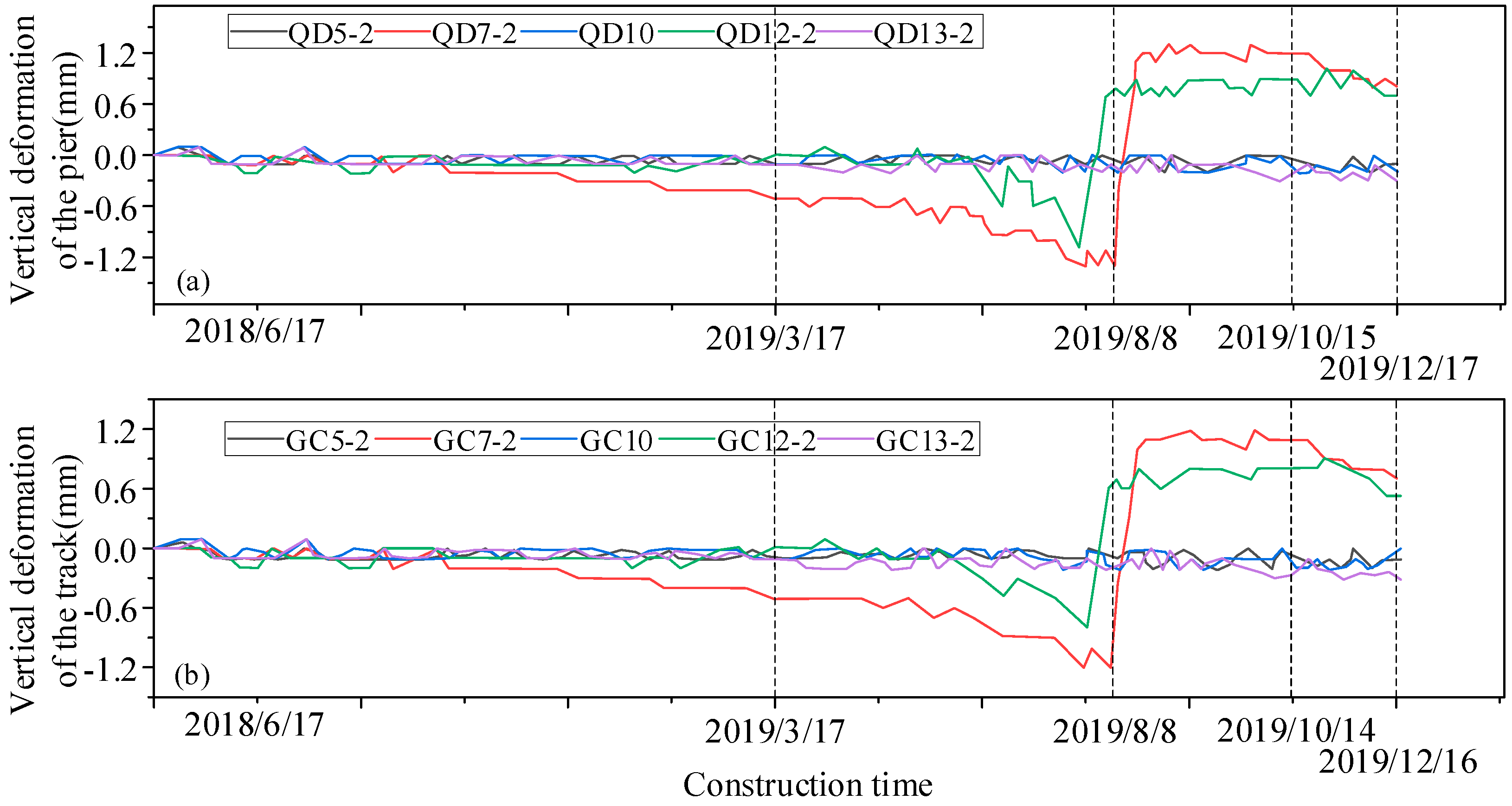
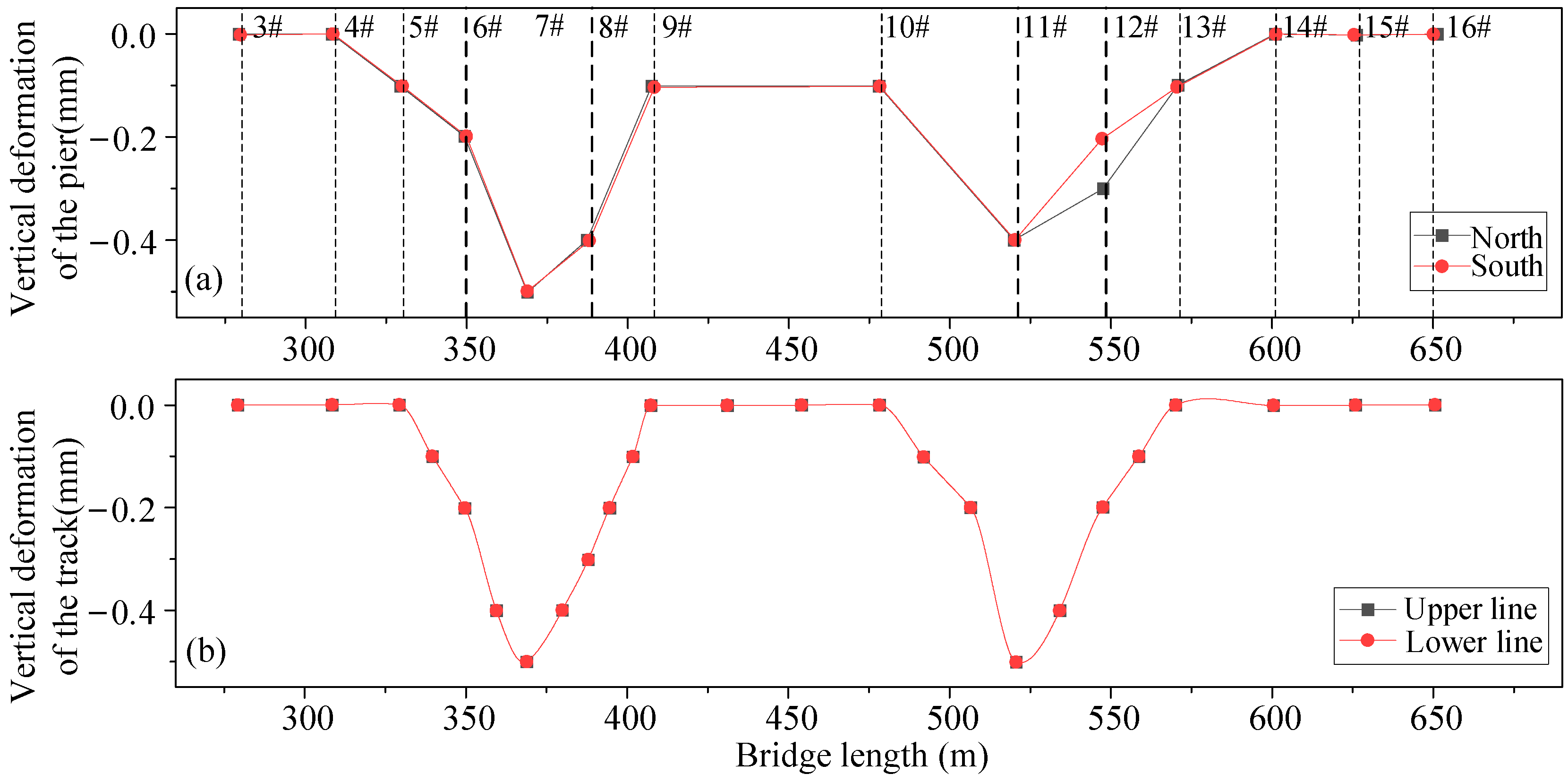
Based on the analysis of on-site monitoring data, the deformation characteristics of the bridge structure are as follows: The maximum vertical deformation value of the bridge substructure is 0.8 mm, indicating uplift deformation; the maximum transverse deformation value is −0.5 mm, indicating inward deformation towards the excavation area. These deformations are observed specifically at the pile foundation supporting Pier 7#.
(2)
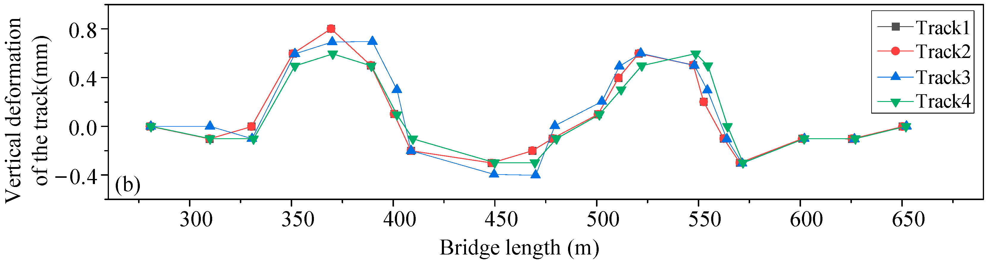
Based on the analysis of on-site monitoring data, the track structure exhibits a deformation pattern. The track structure experiences a maximum vertical uplift deformation of 0.8 mm. Additionally, there is a maximum transverse deformation of −0.5 mm, which is directed towards the inner side of the excavation and corresponds to the maximum deformation of the bridge pier.
(3)
By comparing and analyzing the results of numerical simulations and on-site monitoring data, it has been observed that although there is some discrepancy between the two, the deformation trend is essentially identical. This suggests that the numerical simulation analysis method is a more cost-effective solution for accurately predicting the deformation of the bridge and track.
(4)
By utilizing numerical modeling and manipulating the values of enclosure structure parameters such as the insertion ratio of embedment depth, pile diameter, and pile distance, a comprehensive analysis is conducted on the sensitivity of the deformation of the piers at the adjacent road pit to these parameters. The results show that the effects of the embedment depth of the enclosing piles, the diameter of the enclosing piles and the spacing of the enclosing piles on the deformation of the piers decrease in that order.
(5)
As the insertion ratio of the embedment depth of the enclosing pile and the diameter of the enclosing pile increase, the deformation of the piers decreases in magnitude. Conversely, as the distance of the enclosing pile increases, the deformation of the piers increases in magnitude. The vertical and transverse deformations of the piers are logarithmically correlated with the ratio of the depth at which the enclosing pile is inserted, the diameter of the enclosing pile, and the spacing between the piles.
(6)
This thesis is limited to the study of the deformation effects of pile buttressing and foundation construction only under the soil conditions of alternating clay, silt, and fine-to-medium sands and lacks relevant studies on the stratigraphy of coastal areas or other special soil areas.

Author Contributions

Conceptualization, H.P.; Methodology, H.P.; Validation, H.P.; Formal analysis, S.T.; Investigation, S.T. and L.Z.; Resources, S.T. and L.Z.; Data curation, S.T. and G.W.; Writing—original draft, H.P.; Writing—review & editing, B.M.; Visualization, G.W.; Supervision, G.W.; Project administration, S.T.; Funding acquisition, S.T. All authors have read and agreed to the published version of the manuscript.

Funding

This research was funded by Science and Technology Research and Development Project of China State Railway Group Co., Ltd. grant number L2023G007, L2022G007, Science and Technology Research and Development Program Project of China Railway Group Limited grant number 2020-Special-02, 2021-Special-08 and Hunan National Natural Science Foundation grant number 2021JJ30053.

Institutional Review Board Statement

Not applicable.

Informed Consent Statement

Informed consent was obtained from all subjects involved in the study.

Data Availability Statement

The original contributions presented in the study are included in the article, further inquiries can be directed to the corresponding author.

Conflicts of Interest

Author Sui Tan was employed by the company China Railway Group Limited. The remaining authors declare that the research was conducted in the absence of any commercial or financial relationships that could be construed as a potential conflict of interest.

References

  1. Soomro, M.A.; Mangi, N.; Mangnejo, D.A.; Memon, N.A. 3D centrifuge numerical modelling of lateral responses of a vertical loaded pile group to twin stacked tunnels. Eur. J. Environ. Civ. Eng. 2022, 26, 5517–5544. [Google Scholar] [CrossRef]
  2. Li, Z.; Chen, Z.; Wang, L.; Zeng, Z.; Gu, D. Numerical simulation and analysis of the pile underpinning technology used in shield tunnel crossings on bridge pile foundations. Undergr. Space 2021, 6, 396–408. [Google Scholar] [CrossRef]
  3. Zhang, C.; Zhao, Y.; Zhang, Z.; Zhu, B. Case Study of Underground Shield Tunnels in Interchange Piles Foundation Underpinning Construction. Appl. Sci. 2021, 11, 1611. [Google Scholar] [CrossRef]
  4. Iwasaki, Y.; Watanabe, H.; Fukuda, M.; Hirata, A.; Hori, Y. Construction control for underpinning piles and their behaviour during excavation. Geotechnique 1994, 44, 681–689. [Google Scholar] [CrossRef]
  5. Zheng, Y.; Hu, Z.; Ren, X.; Wang, R.; Zhang, E.; Long, Z. Effects of Partial Supporting Pile Removal from Deep Foundation Pits by Shallow Excavation Method in Loess Areas. Adv. Mater. Sci. Eng. 2021, 2021, 9934113. [Google Scholar] [CrossRef]
  6. Xiang, Y.; Jiang, Z.; He, H. Assessment and control of metro-construction induced settlement of a pile-supported urban overpass. Tunn. Undergr. Space Technol. 2008, 23, 300–307. [Google Scholar] [CrossRef]
  7. Shan, H.; Yu, F.; He, S.; Xia, T. Influence of Soil Excavation on Bearing Behavior of Pile Group Foundation Composed of Underpinning Piles and Existing Piles. J. Test. Eval. 2024, 52, 20230236. [Google Scholar] [CrossRef]
  8. Hu, Y. Risk Analysis of Subway Crossing Irregular-Plate Bridge and Technical Scheme of Controllable Active Pile Underpinning. Int. J. Perform. Eng. 2018, 14, 3195. [Google Scholar] [CrossRef]
  9. Makarchian, M.; Poulos, H.G. Simplified Method for Design of Underpinning Piles. J. Geotech. Eng. 1996, 122, 745–751. [Google Scholar] [CrossRef]
  10. Wu, D. Research on the Shield Tunneling Construction Passing Through the Maglev Pile Foundations in Saturated Soft Soil Strata. In Proceedings of the 4th GeoShanghai International Conference on Tunneling and Underground Construction, Shanghai, China, 27–30 May 2018; Zhang, D., Huang, X., Eds.; pp. 576–584. [Google Scholar]
  11. Voznesensky, A.A.; Mazein, S.V. Studying the variation of rotor pressing forces and horizontal soil pressure during shield tunneling. J. Min. Sci. 2012, 48, 233–240. [Google Scholar] [CrossRef]
  12. Bouayad, D.; Emeriault, F.; Maza, M. Assessment of ground surface displacements induced by an earth pressure balance shield tunneling using partial least squares regression. Environ. Earth Sci. 2015, 73, 7603–7616. [Google Scholar] [CrossRef]
  13. Xie, D. Experimental study of tunnelling technology combining a boom-type roadheader with smooth blasting. Mod. Tunn. Technol. 2015, 52, 216–219. [Google Scholar]
  14. Xing, X.K.; Zhang, J.W. Experimental study on the distribution law of pressure arch under the condition of soil reinforcement around tunnel. Railw. Build. 2014, 47–50. (In Chinese) [Google Scholar]
  15. Xie, X.Y.; Wang, Q.; Qi, Y.; Li, J.; Yu, X. Research on settlement control technology of mud-water shield tunneling underneath houses in conglomerate mudstone composite stratum. J. Geotech. Eng. 2017, 39, 1591–1599. (In Chinese) [Google Scholar]
  16. Patricia Lopez-Acosta, N.; Martinez-Hernandez, E. Underpinning and Releveling of a Building Using Control Piles and Sub-Excavation. In Proceedings of the Geotechnical Engineering in the XXI Century: Lessons Learned and Future Challenges, Cancun, Mexico, 17–20 November 2019; Lopezacosta, N.P., Martinezhernandez, E., Espinosasantiago, A.L., Mendozapromotor, J.A., Lopez, A.O., Eds.; 16th Pan-American Conference on Soil Mechanics and Geotechnical Engineering (PCSMGE). pp. 1094–1101. [Google Scholar]
  17. Wang, C.; Han, J.; Kim, S.; Jang, Y. A novel preloading method for foundation underpinning for the remodeling of an existing building. Geomech. Eng. 2021, 24, 29–42. [Google Scholar]
  18. Ma, L.; Wang, J. Technology of Pile Foundation Underpinning in Shield Tunnel of Xi’an Subway. Appl. Mech. Mater. 2012, 204–208, 1445–1448. [Google Scholar] [CrossRef]
  19. Xu, Q.; Zhu, H.; Ma, X.; Ma, Z.; Li, X.; Tang, Z.; Zhuo, K. A case history of shield tunnel crossing through group pile foundation of a road bridge with pile underpinning technologies in Shanghai. Tunn. Undergr. Space Technol. 2015, 45, 20–33. [Google Scholar] [CrossRef]
  20. Wang, W.; Yao, J.; Yue, J.; Lan, W. Key techniques and application of underground space development underneath heritage buildings in soft soil. Jianzhu Jiegou Xuebao/J. Build. Struct. 2023, 44, 92–99. [Google Scholar]
  21. Huang, S.; Liu, J.; Tian, W. Research on the Underpinning and Deformation Control of Pile Foundation in Tunnel under Bridge. J. Railw. Eng. Soc. 2023, 40, 9–14. [Google Scholar]
  22. Zhang, Q.; Liu, M. Analysis of the impact of comprehensive pipeline corridor pit excavation on neighboring bridge pile foundation. Shandong Transp. Sci. Technol. 2019, 107–108, 146. (In Chinese) [Google Scholar]
  23. Xiong, M.X.; Luo, X.D.; He, G.W.; Fang, W. Analysis of viaduct pile buttresses and pit settlement and deformation under the influence of pit excavation. Constr. Technol. 2019, 48, 52–57. (In Chinese) [Google Scholar]
  24. Fan, Z.W. Intercity railroad shield tunnel crossing highway bridge pile foundation replacement technology. Transp. World 2019, 31–32. (In Chinese) [Google Scholar] [CrossRef]
  25. Peng, H.; Wang, X.J.; Li, Z.C.; Li, R.; Xiao, X. Research on deformation control of deep foundation pit project underpassing elevated railway bridge by pile foundation replacement technology. In Proceedings of the 33rd National Conference on Structural Engineering (Volume II), Liaoning, China, 18 October 2024. (In Chinese). [Google Scholar]
  26. Reza, I.; Mohsen, Z.; Danial, G. Relative contribution of various deformation mechanisms in the settlement of floating stone column-supported foundations. Comput. Geotech. 2021, 134, 104109. [Google Scholar]
Figure 1. Schematic diagram of the pile foundation underpinning project.
Applsci 14 06357 g001
Figure 2. Schematic diagram of the underpinning structure.
Applsci 14 06357 g002
Figure 3. The engineering geological conditions [25].
Applsci 14 06357 g003
Figure 4. Pictures of construction site. (a) Existing bearing platform reinforcement and ground support roof system. (b) Jack installation. (c) Replacement of beam side formwork. (d) Joist construction.
Applsci 14 06357 g004
Figure 5. Layout of measuring points for the existing subway bridge pier structure.
Applsci 14 06357 g005
Figure 6. Detailed layout of vertical displacement measuring points of track structure.
Applsci 14 06357 g006
Figure 7. Schematic diagram of existing subway lines.
Applsci 14 06357 g007
Figure 8. Final vertical deformation of the piers of existing subway viaducts [25]. (a) The vertical deformation of the piers. (b) Comparison of vertical displacement of track.
Applsci 14 06357 g008aApplsci 14 06357 g008b
Figure 9. Time history diagram of vertical deformation of typical bridge pier measuring points. (a) Time course diagram of vertical deformation of bridge abutments. (b) Vertical deformation time course diagram of the track.
Applsci 14 06357 g009
Figure 10. Ultimate transverse deformation of existing viaduct piers [25]. (a) Final transverse deformation map of the measured points of the subway viaduct abutments. (b) Final lateral deformation map of the track structure.
Applsci 14 06357 g010
Figure 11. Three-dimensional finite element overall model [25].
Applsci 14 06357 g011
Figure 12. Comparison of the final vertical deformation model calculation value and the field monitoring value of the north pier. (a) Comparison of simulated and monitored vertical deformation of bridge abutments. (b) Comparison of track simulation and monitored vertical deformation.
Applsci 14 06357 g012
Figure 13. Comparison of vertical deformation time history of bridge Pier 7-1# at pile foundation underpinning [25]. (a) Vertical deformation time-course plots for abutment simulation and monitoring. (b) Time course of vertical deformation for track simulation and monitoring.
Applsci 14 06357 g013
Figure 14. Comparison of the final transverse deformation of the pier on the north side. (a) Comparison of lateral deformation of bridge abutments. (b) Comparison diagram of transverse deformation of track.
Applsci 14 06357 g014aApplsci 14 06357 g014b
Figure 15. Jack layout plan design [25].
Applsci 14 06357 g015
Figure 16. A finite element model of a subway viaduct structure [25].
Applsci 14 06357 g016
Figure 17. Vertical deformation of the north side bridge pier during each process of pile foundation underpinning [25]. (a) Vertical deformation diagrams for typical points of the abutment at each process. (b) Vertical deformation of typical points of rail at each process.
Applsci 14 06357 g017
Figure 18. Time history diagram of vertical deformation of typical bridge piers [25]. (a) Comparison of vertical deformation values of abutments at different locations for each process. (b) Comparison of vertical deformation values of tracks at different locations in each process.
Applsci 14 06357 g018
Figure 19. Transverse deformation of the north side bridge pier during each process of pile foundation underpinning [25]. (a) Comparison of lateral deformation values of abutments at different locations in each process. (b) Comparison of transverse deformation values of tracks at different locations in each process.
Applsci 14 06357 g019
Figure 20. Changes in the level of the track under each process. (a) Plot of changes in track level displacement for the upbound line. (b) Plot of changes in track level displacement for the downstream line.
Applsci 14 06357 g020
Figure 21. Track gauge changes in each process. (a) Chart of track gauge changes on the up line. (b) Graph of track gauge changes on the downstream line.
Applsci 14 06357 g021
Table 1. Summary of pier pile foundations of existing subway viaducts.
Pier NumberDiameter of the Pile (m)Length of the Pile (m)Number of the Pile (Piece)
3# ϕ 1304
4#306
5#306
6#306
7#306
8#326
9#359
10#359
11#326
12#306
13#306
14#304
15#304
16#304
Table 2. Groundwater level survey.
Serial NumberGroundwater TypeDepth of Groundwater Level
(Pressure Head of Confined Water)
Buried Depth of Water Level (m)Water Level Elevation (m)
1Phreatic water6.40~12.3010.57~13.79
2Confined water13.209.67
Table 3. Deformation control value of the temporary retaining pile structure of the underpinning foundation pit.
Control IndexPrewarning Value (mm)Alarm Value (mm)Controlling Value (mm)
Foundation pit retaining piles where the abutment needs to be underpinnedHorizontal displacement7.08.010.0
Rate of deformation2.0 mm/d
Table 4. Deformation control index of the pile foundation underpinning stage.
Control IndexPrewarning Value (mm)Alarm Value (mm)Controlling Value (mm)
Structure and track within the viaductVertical deformation2.12.43.0
Lifting capacity of the bridge structure2.12.43.0
Transverse deformation2.12.43.0
Table 5. Deformation control index during foundation pit construction.
Control IndexPrewarning Value (mm)Alarm Value (mm)Controlling Value (mm)
Structure and track within the viaductVertical deformation3.54.05.0
Transverse deformation2.12.43.0
Table 6. Allowable deviation of static geometric dimensions of track structure.
ItemComprehensive Maintenance (mm)
Gauge+4, −2
Horizontal4
Vertical4
Table 7. Physical parameters of the soil layer.
NameDensity
(g/cm3)
Angle of Internal FrictionCohesion (kPa)Poisson’s RatioModulus of Elasticity (MPa)
Miscellaneous fill1.755100.312.0
Powdery clay1.9618250.330.0
Chalky soil2.0123-0.3332.0
Fine-to-medium sand2.0830-0.2480.6
Clay1.8414.523.60.2621.3
Table 8. Physical and mechanical parameters of the existing subway viaduct structure and road-deep foundation pit engineering enclosure structure.
Serial NumberNameNatural Density (g/cm3)Poisson’s Ratio vModulus of Elasticity
(MPa)
1Spinning pile shotcrete2.10.1825.0
2Retaining piles, diaphragm walls2.50.2030.0
3Bridge structures2.30.2233.5
Table 9. Deviation value of front and back height of subway track in each process.
ProcessVertical Deformation within 10 m Chord Length (mm)
Upper LineLower Line
Process 10.0520.053
Process 20.3500.357
Process 31.2971.266
Process 40.9410.967
Disclaimer/Publisher’s Note: The statements, opinions and data contained in all publications are solely those of the individual author(s) and contributor(s) and not of MDPI and/or the editor(s). MDPI and/or the editor(s) disclaim responsibility for any injury to people or property resulting from any ideas, methods, instructions or products referred to in the content.

