1. Introduction
The circular knitting machine, as one of the main pieces of textile equipment, holds a market share and retention rate of over 60% in the textile equipment market. In the knitting process, the magnetic levitation knitting equipment performs in a manner consistent with traditional mechanical transmission knitting equipment, relying on a series of cyclic actions such as loop formation, yarn hooking, closing, loop development, pulling, and re-looping. The traditional circular knitting machine uses a mechanical drive method, which inevitably results in friction wear, rigid impacts, and operational noise due to mechanical movements. Based on the magnetic levitation needle drive theory, Wu Xiaoguang et al. [
1] proposed a new type of needle selection mechanism for knitting machines that utilizes electromagnetic force to drive the needles, replacing traditional multi-stage transmissions with zero transmission. This improvement enhances the transmission efficiency of the needles and reduces breakage rates. However, due to the high operating speed of magnetic levitation needles, the magnets heat up with increased usage and operating time, leading to increased resistance, decreased current, and consequently affecting the performance of the magnetic levitation needles. The existing maintenance strategies typically employ regular inspections, but this method cannot detect problems in a timely manner. In recent years, many scholars have conducted a series of studies on the online monitoring of circular knitting machine needles, but issues such as low real-time [
2] performance, poor visualization effects, low accuracy in needle fault diagnosis, inability to accurately identify damaged needles, and poor overall evaluation and optimization of needle movement still persist [
3]. Therefore, to ensure the stable and reliable operation of the monitoring system and to promptly detect and stop the equipment in the event of a fault, the research method proposed in this paper is of significant importance.
In recent years, the relationship between digital twins and the Fourth Industrial Revolution has become increasingly close, making digital twins an essential component of modern industrial development [
4,
5]. According to statistical data, 60% of domestic manufacturing enterprises have automated production lines, but nearly 70% of these companies lack adequate digital capabilities. Only 32% of manufacturing enterprises have completed basic digital capability construction for their manufacturing sites, and only 12% have achieved the effective monitoring of data-based manufacturing processes. There is still a lack of underlying software support for monitoring and scientifically managing the operational status of manufacturing workshops. With the disappearance of the demographic dividend and the industrial transformation and upgrade, enterprises urgently need to improve the automation and intelligence levels of their production lines. At least 40% of enterprises plan to digitally upgrade their automated production lines, with production line monitoring and health management being the primary tasks of the upgrade. However, traditional digital workshop and production line simulation technology solutions mainly address workshop layout planning and production line optimization issues. Due to the large volume of three-dimensional models and poor real-time interactions between simulation systems and hardware device data, it is impossible to achieve the real-time mirroring of physical workshops and reverse the time reproduction of production processes. Therefore, these solutions are difficult to directly use for real-time visual monitoring and remote operation and maintenance, thereby limiting the textile industry’s transition to intelligence and automation.
The emergence of digital twin technology provides an effective solution for the “three modernizations” (digitization, intelligence, and networking) of enterprises. Many scholars at home and abroad are actively engaged in the research and practice of digital twin technology, achieving significant results. Tao Fei et al. considered the ten major issues of digital twins and introduced the concept of a five-dimensional model of digital twins [
6], providing a theoretical basis and ideas for the application of digital twins in product design technical applications and lifecycle maintenance [
7]. As a key enabling technology for intelligent manufacturing [
8], digital twins create dynamic virtual models of physical entities with multiple dimensions, time–space scales, disciplines, and physical quantities to simulate and describe the properties, behaviors, and laws of physical entities in real environments [
9]. Yixiong Wei, Lei Guo, and others proposed a real-time data-driven digital twin workshop system architecture and technical route [
10]. By constructing a virtual simulation environment of actual physical behaviors and using event-responsive data management methods, they achieved real-time visual monitoring, health management, and intelligent workshop production status fault diagnosis. Zhang Chao and others proposed a multi-dimensional, multi-scale intelligent spatial model of digital twin manufacturing units and high-fidelity modeling methods [
11]. Dezhuang Meng and others suggested that digital twins establish virtual models of physical entities in a digital manner [
12], using historical data, real-time data, and algorithmic models to simulate, verify, predict, and control the entire lifecycle of physical entities.
This paper, based on the five-dimensional digital twin model, proposes a digital twin architecture for an online monitoring system of magnetic levitation knitting needles, as shown in
Figure 1. Currently, circular knitting machine needles have been applied in various fields such as product design, manufacturing, visual monitoring, and intelligent operation and maintenance. However, the construction and research of digital twin systems for magnetic levitation-driven circular knitting machine needles have not been reported, and cannot meet the intelligent development needs of circular knitting machines. This online monitoring system monitors the magnetic levitation knitting needle system through a three-dimensional visualization and information statistics panel. The system can monitor the operating status of the device in real-time, provide feedback on data, and achieve the real-time monitoring of the magnetic levitation knitting needle system, thus advancing the field.
The structure of this paper is as follows:
Section 2 proposes a five-dimensional architecture for the digital twin monitoring platform of the magnetic levitation knitting needle system, based on the concept of the five-dimensional digital twin model. This section focuses on three main aspects—the establishment of the virtual model of the magnetic levitation knitting system, data acquisition and transmission, and the integration of the magnetic levitation knitting system monitoring platform.
Section 3 analyzes the key technologies of the digital twin monitoring platform.
Section 4 presents experimental cases and analysis.
Section 5 provides the conclusions.
2. Theoretical Framework of the Digital Twin Monitoring System
As shown in
Figure 1, this paper combines the five-dimensional digital twin model and takes the magnetic levitation knitting needle as the research object to propose a five-dimensional architecture for the digital twin monitoring system of the magnetic levitation knitting needle system. This architecture consists of five dimensions—physical entities, virtual models, twin data, connections, and services [
13]—with interaction and iterative optimization among these dimensions.
The construction of this monitoring system platform can be mainly divided into the following four steps: visualization interface design, virtual model construction, real-time data acquisition, and hardware device driving. The visualization platform design involves displaying the model in a virtual space and using a roaming perspective to monitor the state of various positions of the model, with the operation data of the knitting needles displayed on a visualization dashboard. The virtual model construction is a key aspect of the digital twin model, including geometric model establishment, lightweight processing, baking processing, and rendering processing. Real-time data acquisition involves the real-time collection and analysis of data. Hardware device driving includes sensor data collection, data transmission modules, digital-to-analog conversion using the DAC0832 chip (Texas Instruments, Dallas, TX, USA), and real-time data driving with a microcontroller.
The architecture of the magnetic levitation knitting needle monitoring system is shown in
Figure 2. This system consists of five dimensions—physical entity, virtual model, twin data, connection, and services. By leveraging the dual drive of multi-dimensional virtual models and integrated data, and the interaction between the physical entity and the virtual model, the digital twin platform achieves comprehensive monitoring. The system acquires real-time data from the magnetic levitation knitting needles through the physical entity and controls the operation of the device. It then processes modeling, planning, and data interaction transmission in the data layer, and uses the virtual layer for data visualization.
2.1. Physical Entity
The physical entity and its corresponding virtual model, data, connection, and services are the core components of a digital twin [
14]. In the magnetic levitation knitting needle system, the physical entity primarily refers to components such as the needle cylinder, sinkers, sensors, knitting needles, and bearings, which serve as the objects of twin data.
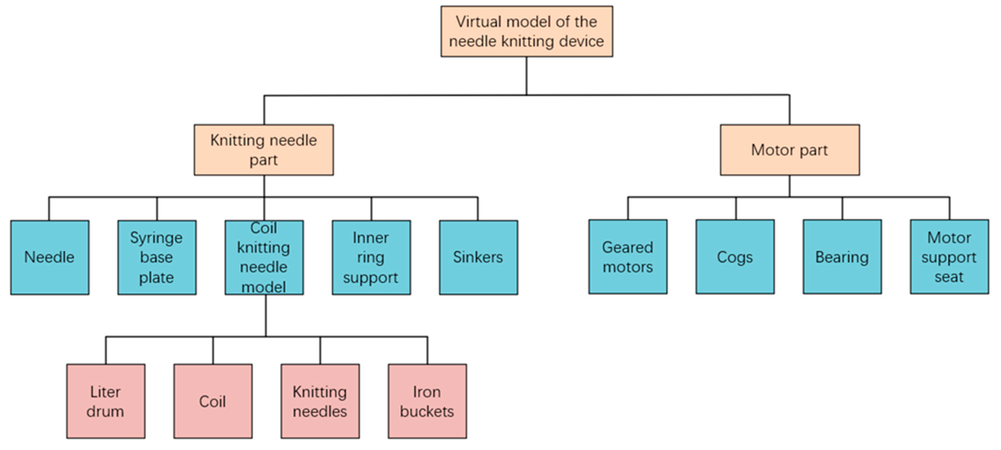
2.2. Virtual Model
The virtual model is the digital representation of the physical entity in a digital space. It mainly includes the geometric model of the new 5-inch 32-needle magnetic levitation circular knitting machine system, the physical model for structural and magnetic field analysis of the knitting needle system, the behavioral model of the knitting needle system created based on neural network algorithms, the rules model for real-time judgment, evaluation, and optimization of the knitting needle system created based on historical associative data.
2.3. Twin Data
Twin data primarily include physical data from the new magnetic levitation knitting needle system: physical needle dimensions, parameters, specifications, materials, etc.; virtual data: assembly relationships, material properties, driving factors, and associated rules of virtual needles; service application data: data processing methods, algorithms, etc.; knowledge data: knitting needle system motion standards, rules, professional knowledge, etc. [
15].
2.4. Connect
Connection is the key to the digital twin system, facilitating real-time data exchange, collection, and driving across various layers of the system by linking each layer’s structures.
2.5. Services
Services refer to comprehensive connection services provided for connection, such as data collection, communication protocols, interface protocols, etc. In addition to this, digital twins require the encapsulation of various models, algorithms, data, simulations, and results into service-oriented packages during specific operation processes.
4. Experimental Case
The needle system of the magnetic levitation drive knitting circular knitting machine is chosen as the research object for this experiment. The diameter of the needle cylinder in the magnetic levitation drive needle system is 5 inches with a 32-needle array, and the needle pitch is approximately 9 mm. Due to the “zero transmission” characteristic of magnetic levitation drive, the needle movement frequency is faster and the spacing between needles is smaller, making the real-time monitoring of needle movement more challenging. In order to intuitively, realistically, and accurately display the technological status of the magnetic levitation needles during the weaving process, achieve the rapid positioning of the 32 needles, the real-time visualization of information, intelligent control, and improve the operational efficiency and overall management level of the magnetic levitation needle system, online monitoring and predictive analysis of the magnetic levitation needle system based on the digital twin architecture of the magnetic levitation needle monitoring system are conducted.
4.1. Three-Position Motion Trajectory of Magnetic Levitation Needles
The magnetic levitation needles use electromagnetic drive to enable permanent magnetic needles to achieve three working modes of ring forming, loop gathering, and floating line directly under electromagnetic force. As shown in
Figure 9, based on the analysis of the three-position motion trajectory of magnetic levitation needles, the weaving process is divided into ring forming, ring holding, ring descending, floating line, loop gathering, loop holding, loop descending, and floating line.
Table 1 represents the movement process of a single needle position. From
Figure 9 and
Table 1, it can be seen that the needle completes one ring forming, one floating line, and one loop gathering action in one cycle (time period A–G). The table divides one motion cycle of the needle into seven time periods.
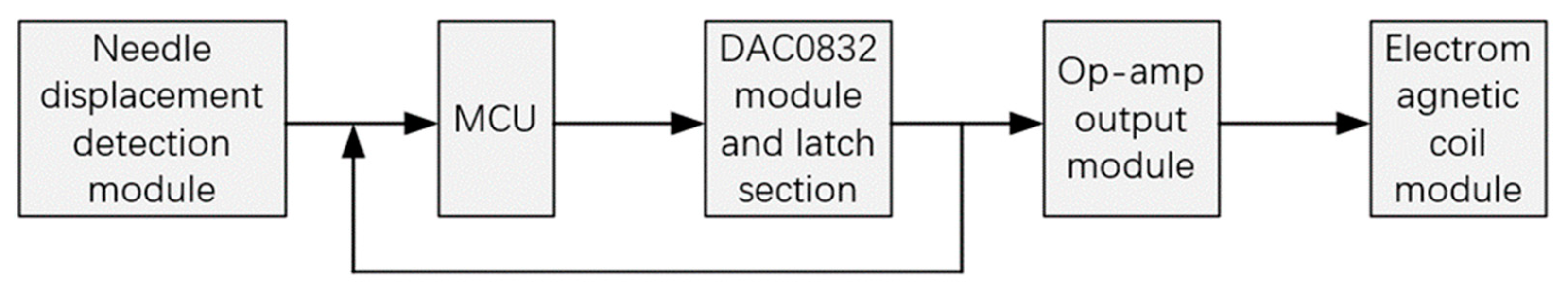
Assuming there is no coupling between the magnetic field and the electric field, the magnetic field and the electric field can be analyzed separately in a static-steady electromagnetic field. However, in actual environments, the electric field and the magnetic field are often changing, requiring the analysis of transient electric and magnetic fields. Therefore, coupling phenomena exist between the changing electric field and the changing magnetic field. Continuing to use Maxwell’s equations to solve for transient electromagnetic fields results in a huge computational burden and becomes very difficult. The magnetic induction generated by the current is directly proportional to the magnitude of the current. Therefore, to allow the needle to achieve a larger stroke and to accurately reach the effective height of 9 mm for needle movement, and to fully implement the modes of knitting, gathering, and floating, it is necessary to control the magnitude of the current.
For ease of testing, the control scheme is based on the STC80C51 (Shanghai STMicroelectronics Microelectronics Co., Ltd., Shanghai, China) as the control core, employing current sensors for feedback control. The measurement data from the sensors undergo analog-to-digital conversion through an A/D module and are then transmitted to the CPU of the microcontroller for processing, forming a closed-loop system. The closed-loop control system is illustrated in
Figure 10. The feedback terminal of the drive chip is connected to the analog conversion chip, enabling feedback control by the CPU. The hardware device and circuit experimental platform for the multi-needle magnetic levitation drive control technology are depicted in
Figure 11.
Through experimental methods, ten points between 0 and 9 mm are selected. By adjusting the LM2575adj, the required current for the needle at each point is measured. The data in
Table 2 are stored inside the control chip in the form of a ROM table, and are then converted into analog signals through the DAC0832 digital-to-analog conversion chip for output. The current values are output every 0.05 s in an arithmetic progression pattern, driving the electromagnetic coil to move the needle through the three working positions. When multiple needles need to be magnetically suspended and driven, the feedback data of each channel sensor need to be compared to detect the current displacement of the needle.
4.2. Implementation of the Magnetic Levitation Knitting Needle Online Monitoring System
The system uses the Unity3D engine for system development and design. Lightweight geometric models of the magnetic levitation knitting needle system are constructed based on 3ds Max and SolidWorks 3D modeling software. These models are then imported into the Unity3D platform for baking, rendering, and visualization canvas setup. The OPC-UA interface functions are named based on the .NET platform, and C# script programming is used to establish connections and data exchange between the OPC-UA client in the digital virtual world and the OPC-UA server in the physical world. The movement logic of the knitting needle and human–machine interaction are controlled through C# script components, ultimately achieving intelligent 3D visualization control between the magnetic levitation knitting needle and the model.
Figure 12 shows the 3D visualization monitoring interface of the magnetic levitation knitting needle.
The virtual model in this monitoring system is a mirror mapping of the actual knitting needle system, and the system environment and layout are consistent with the actual knitting needle system. During the knitting motion process of the needle system, real-time data streams continuously drive the movement of the virtual needle. When the needle system starts, it first reads the process flow from the database and converts it into the movement process of the needle in the system. Upon receiving the motion signal, a single needle determines the real-time process based on the signal data information, and the actual needle executes action commands based on the drive data. The twin model of the needle undergoes corresponding 3D model changes, successively fitting the discrete real-time position data of the needle into a continuous knitting motion process.
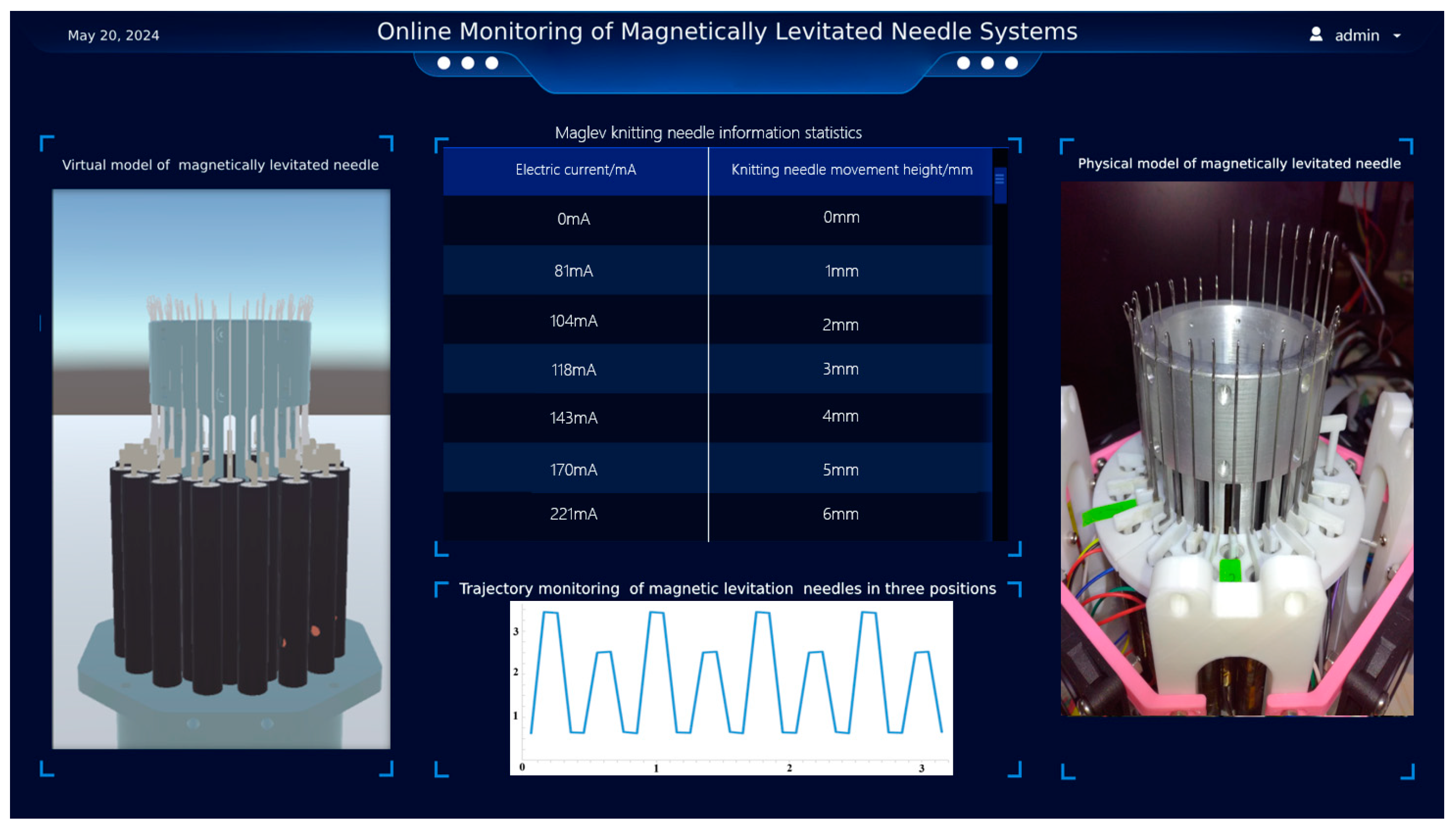
During actual operation, various states of the magnetic levitation knitting needle system, motor information, and other parameters need to be monitored. To intuitively and comprehensively display the operation process information of the entire magnetic levitation knitting needle, the system also constructs a detailed magnetic levitation knitting needle information statistics interface. This interface integrates the equipment model information, user information, and actual operation information of the knitting needle system.
Developed using the Visual Studio platform, the system calls on the ODBC database interface functions to interact with the SQL database and the visualization UI. This completes the visualization of data, including integrated data parsing, statistical chart attribute encapsulation, and data visualization mapping, ultimately achieving a real-time 3D display of information about the magnetic levitation knitting needle. The information statistics interface for the magnetic levitation knitting needle is shown in
Figure 13.
5. Conclusions
Based on the digital twin model, this paper applies digital twin technology to the online monitoring system of the magnetic levitation knitting needle, proposing an online monitoring method for the magnetic levitation knitting needle system based on the digital twin. Research and practice on the magnetic levitation knitting needle device focused on the synchronization of communication between the virtual model and the actual knitting needle system, system human–machine interaction, smoothness of the system monitoring interface, completeness of the system control functions, and accuracy of the diagnostic model as the main testing standards.
By studying the key technologies such as the establishment of the virtual model, drive module, data acquisition module, and visualization module design of the magnetic levitation knitting needle device, online visual monitoring and management of the device were achieved. The system has a high real-time performance, good visualization effects, the ability to conduct multi-faceted prediction, simulation, comprehensive evaluation, and optimization of the magnetic levitation knitting needle device, and it reflects the full lifecycle process of the magnetic levitation-driven knitting needle device.
Experiments verified the feasibility of this method for implementing the digital twin system and the accuracy of monitoring equipment operation. It allows for a more intuitive reflection of the device’s operating status and data changes, enabling timely equipment shutdown when problems are detected, thus improving economic efficiency. The twin interface of the system essentially achieved real-time mapping of the magnetic levitation knitting needle system, completing functions such as needle positioning, needle action synchronization, and system model changes. In a 3D roaming perspective, the image quality is clear and smooth, model actions are seamless, data transmission intervals are 20 ms, the model and the actual knitting needle system maintain synchronization well, the communication synchronization is good, the system is stable, and the human–machine interaction is strong.


 and
and 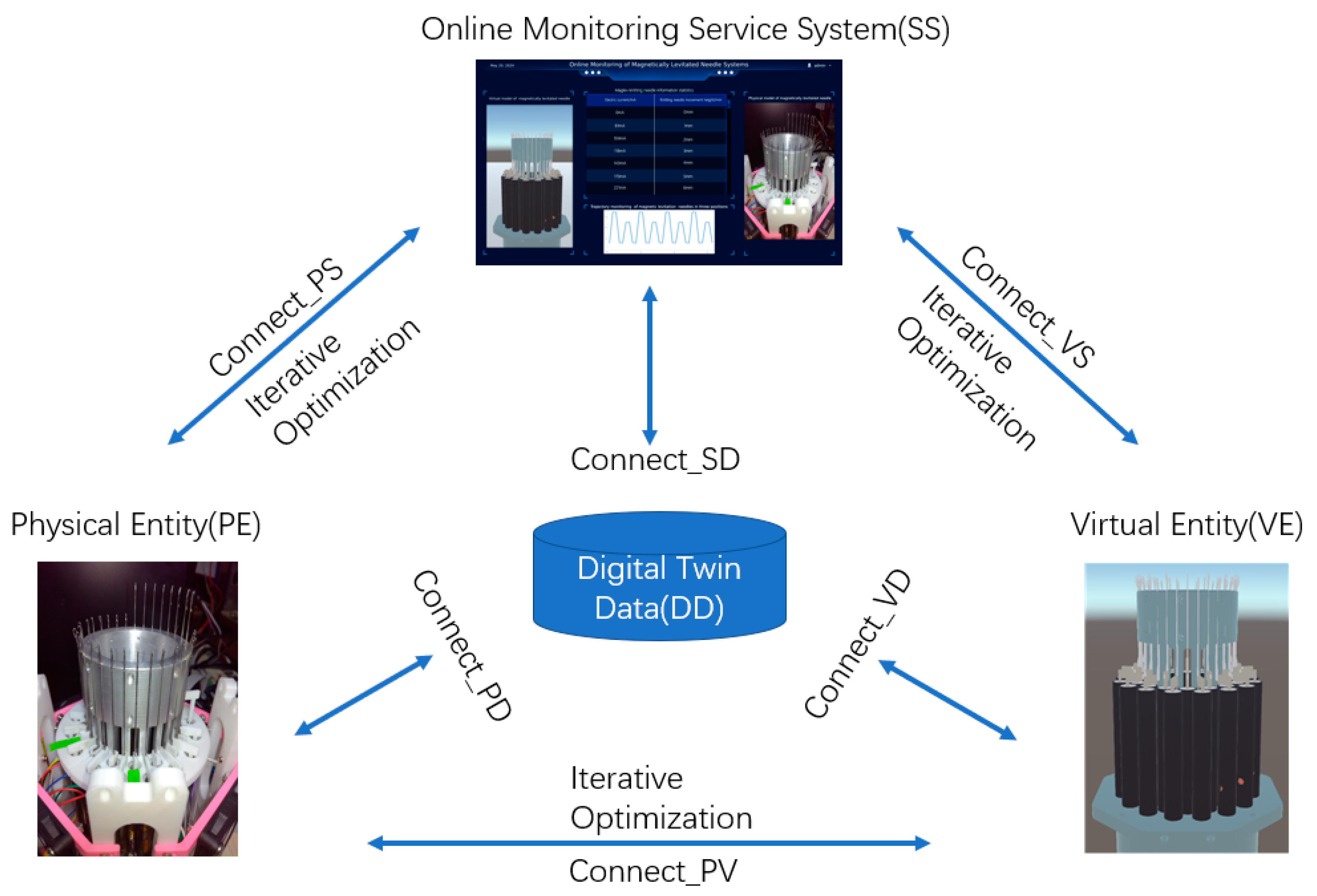


