Article

First Approach in Analysis of Tool Wear When Milling Additive Manufacturing (AM) Parts

Faculty 2: School of Engineering—Technology and Life, HTW Berlin University of Applied Sciences, Wilhelminenhofstraße 75A, 12459 Berlin, Germany
*
Author to whom correspondence should be addressed.
Appl. Sci. 2024, 14(14), 6219; https://doi.org/10.3390/app14146219
Submission received: 31 May 2024 / Revised: 13 July 2024 / Accepted: 13 July 2024 / Published: 17 July 2024
(This article belongs to the Section Materials Science and Engineering)

Abstract

:
Wire arc additive manufacturing (WAAM) and laser-based powder bed fusion (L-PBF) are additive manufacturing (AM) processes that allow the manufacturing of complex part geometries. The manufacturing of AM parts does not result in high-quality functional surfaces; therefore, postprocessing such as milling is usually required. For L-PBF parts, the support structures and, for WAAM parts, the undulating surface are usually removed after AM processes. These two application-related cases are investigated in this work, with the conclusion that support structure milling and the milling of the surface of WAAM parts lead to the dimensionally increased wear of milling tools in comparison to milling of solid material.

1. Introduction

Additive manufacturing (AM) makes it possible to build parts of complex geometries layer by layer [1]. Wire arc additive manufacturing (WAAM) is a process in the Direct Energy Deposition (DED) AM process family [2] and laser-based powder bed fusion (L-PBF) is a widely used technology for metal AM. During the WAAM process, gas metal arc welding is applied to manufacture or repair metallic parts. An advantage of the WAAM process is its relatively high building rates compared to other metal AM processes [3]. During the L-PBF process, the workpiece is built up via melting successive powder layers with a laser. The L-PBF process is mostly used to produce relatively small parts [1].
The microstructure of L-PBF and WAAM parts is characterized by epitaxially growing grains, starting from the base plane. The grains consist of cellular or dendritic structures that form as a result of high cooling rates [4,5]. During both processes, the material undergoes various heating and cooling cycles, resulting in different grain structures that determine the usually anisotropic mechanical properties of the parts [4,5]. Parts built by WAAM and L-PBF are therefore characterized by a specific heat history [6], with the building of every layer resulting in an inherent heat treatment of the already deposited layers.
L-PBF and WAAM parts often require postprocessing machining after the building process to remove support structures and achieve the necessary quality for a functional surface finish [7]. A limited number of investigations are published on the postprocessing of AM parts [8,9]. Ji et al. investigate Inconel 718 (IN718) specimens manufactured with L-PBF compared to wrought parts: micro-milled IN718 L-PBF specimens are less rough and result in lower tool wear compared to conventionally manufactured IN718 [10]. Bonati et al. perform milling tests with Ti6Al4V manufactured with a Laser Engineered Net Shaping (LENS) AM and conclude that the roughness increases with an increase in cutting parameters like the depth of cut and feed rate [11]. Compared to Ti6Al4V LENS, conventionally manufactured material leads to a relatively rougher surface and lower cutting forces due to its lower hardness [11]. Laue et al. compare 316L steel manufactured with different AM processes like L-PBF, WAAM, 3DPMD (3D plasma metal deposition), and conventionally cold rolled variants of the steel using milling tests and point towards the dependence of the milling process of 316L on the manufacturing process [12]. The hardness of the 316L variants increases following this order: 3DPMD, cold rolled, WAAM, and L-PBF [12]. The cutting forces are found to be higher for 316L that has been cold rolled and WAAM, and lowest for L-PBF [12]. The authors explain these dependencies according to their distinct microstructures: L-PBF (lenticular), WAAM (dendritic), 3DPMD (elongated), and cold rolled (homogeneous) [12]. Chernovol et al. state that WAAM process parameters such as travel speed, wire feed speed, and interpass temperature affect postprocessing machining [13]. Shorter cooling times during the WAAM process lead to hard and smooth as-deposited surfaces and therefore result in better chip formation and a better surface finish after machining [13].
In summary, the milling of AM parts differs from the milling of conventionally manufactured parts due to inherent AM process characteristics and the resulting distinct microstructure and material properties of those parts. Postprocessing therefore requires suitable tools and milling process strategies. Moreover, the microstructure and mechanical properties of AM parts are often anisotropic and heterogeneous. Current research does not entirely offer solutions to taking these aspects into account. Also, the removal of support structures, which are used to support the overhanging structures of AM parts and often have lattice geometries, has until now not been a focus of research work.
The aim of this work is a first approach to investigating the milling of AM parts by examining two application-related cases of the mechanical postprocessing of AM: the milling of the surface layer of WAAM parts and the milling of segmented L-PBF support structures, in both cases compared to the milling of solid AM material. These investigations focus on a first approach to tool wear analysis and the resulting forces seen during the milling processes.

2. Materials and Methods

2.1. Test Specimens

Austenitic stainless steel AISI 304H manufactured via WAAM (304H WAAM) by Gefertec GmbH (Berlin, Germany) and nickel superalloy IN718 manufactured via L-PBF (IN718 L-PBF) by Siemens AG (Berlin, Germany) were used to produce test specimens (Figure 1a,b). The standard chemical specifications of the materials are presented in Table 1. The initial 304H WAAM specimen (Figure 1a) was 1610 × 1600 × 22 mm3. The building direction (BD) of the 304H WAAM and IN718 L-PBF specimens is marked in Figure 1a,b, respectively. The IN718 L-PBF specimen had dimensions of 49 × 49 × 60 mm3 and its geometry consisted mostly of support structures (Figure 1b–e) and partially of solid material on the top and bottom of the specimen. The pattern of the support structure shown in Figure 1c,d reveals the cross section of the specimen.

2.2. Milling Tests

The milling tests are performed on a milling center SPINNER U 620 (Spinner Werkzeugmaschinenfabrik GmbH, Sauerlach, Germany). Part 1y, with dimensions 800 × 800 × 22 mm3 (cut according to red lines in Figure 1a), is used for the milling tests of 304H WAAM material within this publication. The milling paths are oriented perpendicularly to the deposited layers and in the building direction (BD). Figure 1b–d show the full IN718 L-PBF material and its supporting structures’ regions. To compare the postprocessing of solid material and support structures, the milling paths lay parallel to the specimen edge and top area (compare Figure 1b,d,e). The milling tests start at the top of the specimen with solid material, with paths 1 to 24 (marked black in Figure 1e), and continue with the support structures’ paths, 1 to 60 (marked gray), positioned under the top solid region. Adjacent milling paths lay parallel to each other and are machined in the same direction for 304H WAAM and IN718 L-PBF.
IN718 L-PBF is investigated, focusing on the tool wear (flank wear land, according to ISO 8688 [16]) and process forces (bending moments), by milling solid and support structure regions of the specimen. Initially, the tool wear was measured as the width of the flank wear land at specified tool travel paths. As the machining of support structures involves only a partial machining of solid material (Figure 1e), the actual cutting volume of the solid material was used as a criterion in order to verify the investigations. The CAD-calculated cutting volume of 2400 mm3 is achieved after milling 12 paths through the solid material or after the machining of 48 paths in the support structures. The investigations are repeated, referring to a volume of 4250 mm3, which represents 22 paths in the solid material and 60 paths in the support structures.
For 304H WAAM, a comparison between the milling of the surface layer and solid material, with a focus on flank wear land and bending moments, similar to the approach used for IN718 L-PBF, was undertaken.
The tools used for the tests are high-performance machining solid carbide end mills manufactured by Seco S.p.a. (Fagersta, Sweden) and are summarized in Table 2. Their base tool geometry is given in [17]. Tool number (1) is used for the IN718 specimen and (2) for the 304H material. The following process parameters are used: feed (fz) 0.06 mm, RPM 1592 min, cutting depth (ap) 2 mm, and width of cut (ac) 2 mm. For IN718 L-PBF, the cutting speed (vc) is 30 m/min and for 304H WAAM it is 90 m/min.
The measurements of the width of the flank wear land are realized by optical microscopy, using the microscope VHX (Keyence Deutschland GmbH, Neu-Isenburg, Germany). During the milling process, the forces and moments are measured by applying the sensory tool holder Spike (Promicron GmbH, Kirchheim am Neckar, Germany). Due to the high fluctuations of the bending moments, the measured values are averaged for every 1500 values.

2.3. Hardness Tests

Hardness measurements of the 304H WAAM specimen are carried out using a 1x specimen (according to Figure 1a). The surface investigated is parallel to the building direction and located on the cutting surface between the 1x and 1y specimen parts. The measurements are conducted at distances 1 mm and 3 mm (middle points of investigated cutting paths) and 11 mm (middle between part surfaces) from the part surface. The Vickers hardness measurements are realized with a fully automated hardness tester Carat 930 (ATM, Mammelzen, Germany), according to [18], with a test load of 10 N (HV1). For each distance from the surface, a total of 23 measurements are conducted in a line with the 2 mm distance between the hardness indentations.

3. Results

3.1. Milling of IN718 LPBF

The analysis of the tool wear progression using the tool travel path is shown in Figure 2. The width of flank wear land is higher in the machining of support structures, compared to solid material machining, for all measurements. In both tests, the wear increases with an increasing number of travel paths.
As the machining of support structures inherently brings a lower material removal rate with it, the tool wear results were verified by analyzing the tool wear in relation to the actual cutting volume; see Figure 3. The results show that when the comparison between the support structure and solid material is standardized to the actual machined volume, the tool wear is still higher when machining support structures.
As the width of the flank wear land is a criterion generally used to quantify the abrasive and surface attrition tool wear mechanisms, this result suggests that the tools are subjected to a higher load related to these tool wear mechanisms when machining support structures. As the machining of support structures brings an alternating load onto the tool surface, a higher level of surface attrition is a logical finding, which can be verified by observing the surface of the cutting edge in microscopy images; see Figure 4.
Figure 4 shows the characteristic wear of the cutting teeth after the machining of the solid material (a) and its support structures (b). Both showed abrasive wear, with the tool used in the machining of support structures also showing evidence of surface attrition.
In explaining the cause of different wear mechanisms in support structure machining, vibrations are decisive. Therefore, bending moments were measured and presented as a function of the tool travel paths (Figure 5). The maximum bending moments of the tools over the first 5 milled paths and their approximated cutting volumes (table below) are presented in Figure 5 for IN718 L-PBF’s solid material and support structures. As can be seen, the variation of the bending moment during the milling of a path was quite different for the solid material and support structures. Clearly, the amplitude of the variation was higher for support structure milling, whilst the absolute values were higher when milling solid material. These differences are likely linked to the alternating material removal rate when machining support structures, and the resulting vibrations.

3.2. Milling of 304H WAAM

The milling of the 304H WAAM specimen showed a higher relative width of its flank wear land when milling the surface layer in comparison to solid material machining after a high number of milling paths (Figure 6). However, in the initial stages of the milling process, tool wear was higher when machining the solid material workpiece, which can be attributed to chipping at the cutting edge.
Figure 7 compares surface images of tool wear after the milling of the surface layer (a,b) and solid material (c,d) of 304H WAAM after 320 mm (a,c) and 3200 mm (b,d) tool travel paths. For all cases presented, the abrasive wear and break-outs at the cutting edge corners are typical.
The bending moments of the first two paths during the milling of the surface and solid regions are shown in Figure 8. A slight increase in bending moments is noted for the surface layer. Although there are some fluctuations in the measured bending moments, the bending moments at the start of the path are typically lower than at the end of the path. As the surface layer has a high variation in planarity due to the manufacturing process, this may be explained by a reduced material removal rate at certain stages of surface layer machining.
Figure 9 shows the results of hardness measurements of the 304H WAAM specimen depending on the distance to the specimen surface. The measurement reveals decreased hardness values for 1 mm and 3 mm distances from the surface (equal to the middles of the cutting paths of the surface layer, 0 to 2 mm, and solid material, 2 to 4 mm from the surface) and the middle of the specimen (11 mm).

4. Discussion

The width of the wear flank land on IN718 L-PBF’s support structures is higher than in the machining of solid material in terms of both tool travel path (Figure 2) and cutting volume (Figure 3). Generally, the higher wear of tools after support structure milling could be explained by differences in tool wear mechanisms. The milling of IN718 as a solid material results in the abrasive wear of tools (Figure 4a), and the machining of support structures additionally results in surface attrition (Figure 4b). Surface attrition is a result of the cyclical thermal and mechanical loading of the tool [19]. Furthermore, the milling of support structures leads to a higher fluctuation in the resulting bending moments. One explanation for this is higher vibrations due to the cyclical loading of the tool, which correlates with the tool wear observations. In Figure 5, the number of peaks of the bending moment per path is 10 and corresponds to the number of nodal points of the support structure per path (compared to Figure 1d,e). The higher the cutting volume per path, the higher the amplitude of the fluctuations of the bending moments. As such, the recurring impact at every support structure beam leads to the fatigue of the tool’s cutting edge, resulting in cracks and pitting.
After milling 304H WAAM, the tools exhibit a more significant increase in wear on the surface layer, particularly for path lengths starting from 1920 mm, compared to the solid material (Figure 6). At path lengths of 640 and 1280 mm, the width of the flank wear land is relatively higher when milling solid material due to the chipping of the tool. The microstructure, and consequently the hardness, often varies within WAAM parts, for example, changing with the height of the part [17]. This variation can account for the differences in tool wear. Moreover, the thermal conditions at the surface differ from those inside the specimen, leading to greater heterogeneity that could affect the results of tool wear.
The measurements of bending moments (Figure 7) from 304H WAAM milling tests indicate that the moments are lower when milling the surface layer, which can be attributed to the material removal rate at the surface compared to the solid material. Considering tool wear, it could be inferred that the surface layer’s hardness is higher than that of the solid layer below, as lower forces resulting in higher tool wear may be due to the higher hardness of the surface region, as the results in Figure 9 show. Differences in microstructure depending on the distance to the surface have also been observed in [20], which supports the assumption of a hardness gradient reported within this study.
Most likely, an abrasive mechanism predominates the tool wear during 304H WAAM milling. The occurrence of corner chipping is also common in both of the aforementioned milling tests, resulting from the overloading of milling tools.

5. Conclusions

Our conclusions for L-PBF parts using IN718 are as follows:
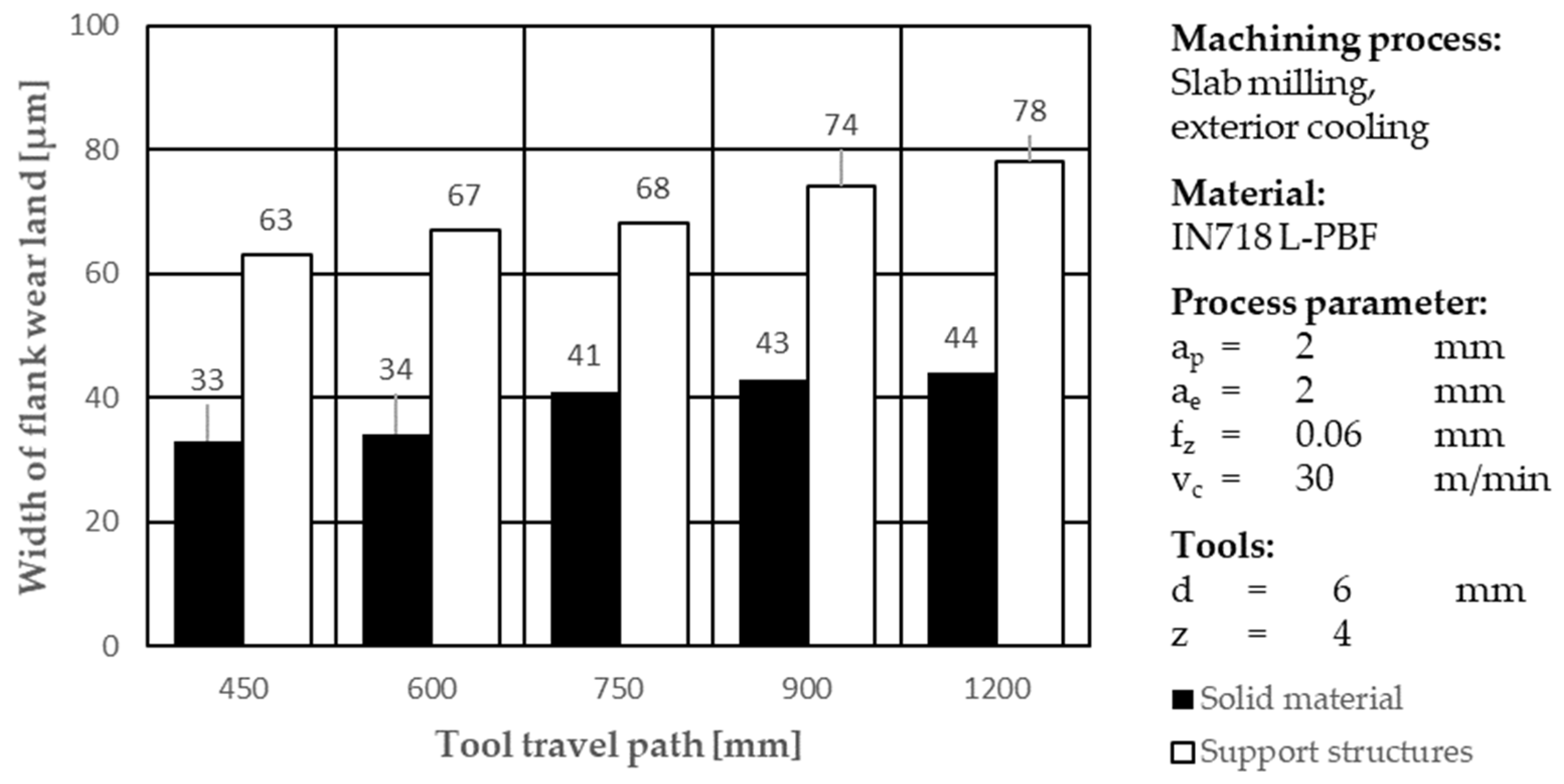
  • Flank wear land width: The width of the flank wear land is larger for support structures compared to solid material for all measurements (Figure 2). Wear increases with the increasing number of travel paths.
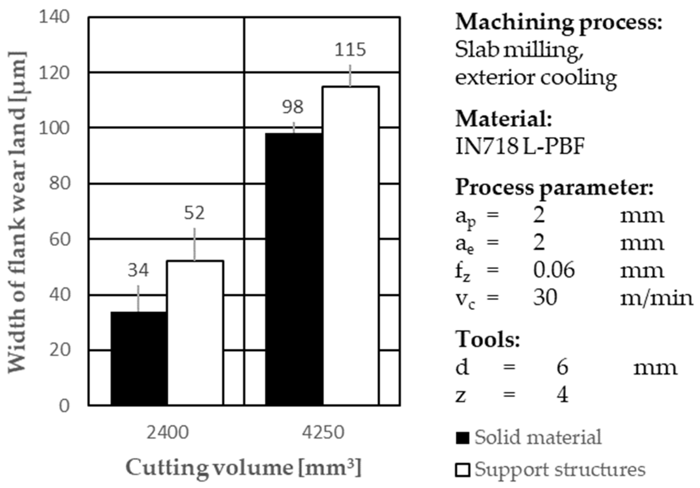
  • Comparison of flank wear land width: When comparing the milling of support structures to solid material, the width of flank wear land is larger in the former after comparable cutting volumes. This suggests that tools are subjected to a higher load related to abrasive and surface attrition wear mechanisms when machining support structures (Figure 3).
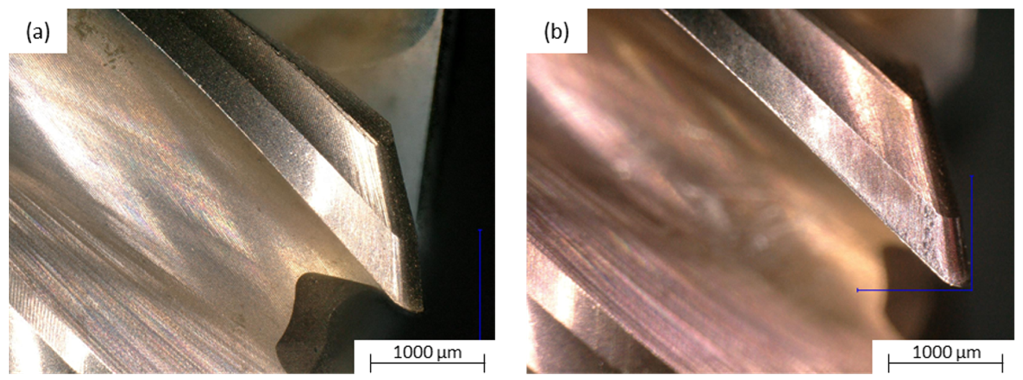
  • Tool wear mechanisms: the milling of support structures results in both abrasive wear and surface spalling, in contrast to the abrasive wear observed when milling solid material (Figure 4).
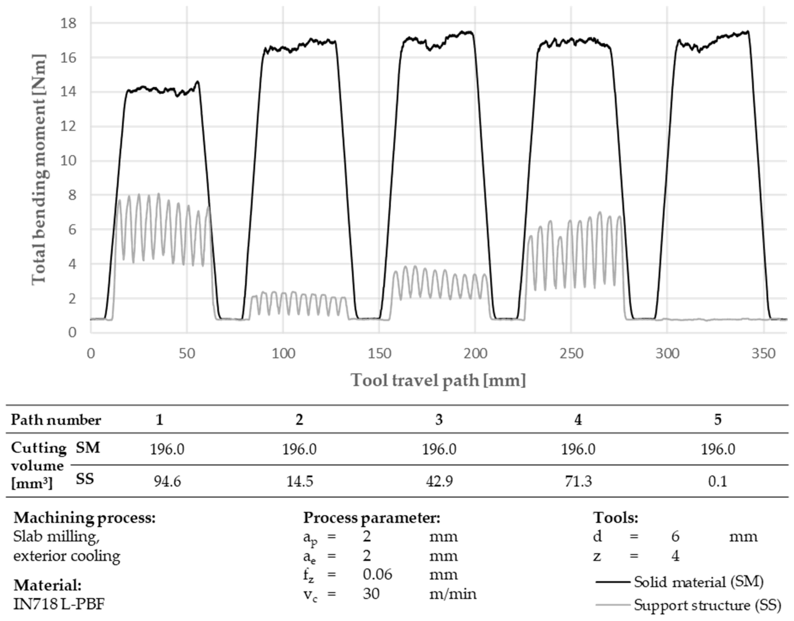
  • Bending moments: bending moments during the milling of support structures vary significantly depending on the position of milling paths within the specimen, indicating the presence of strong vibrations during machining and different material removal rates compared to the machining of solid material (Figure 5).
Our conclusions for WAAM parts using 304H are as follows:
  • Flank wear land width: The width of the flank wear land is relatively larger when milling solid material at path lengths of 640 and 1280 mm. However, after a path length of 1920 mm, the width of the flank wear land remains constant for both areas of the AM material (Figure 6).
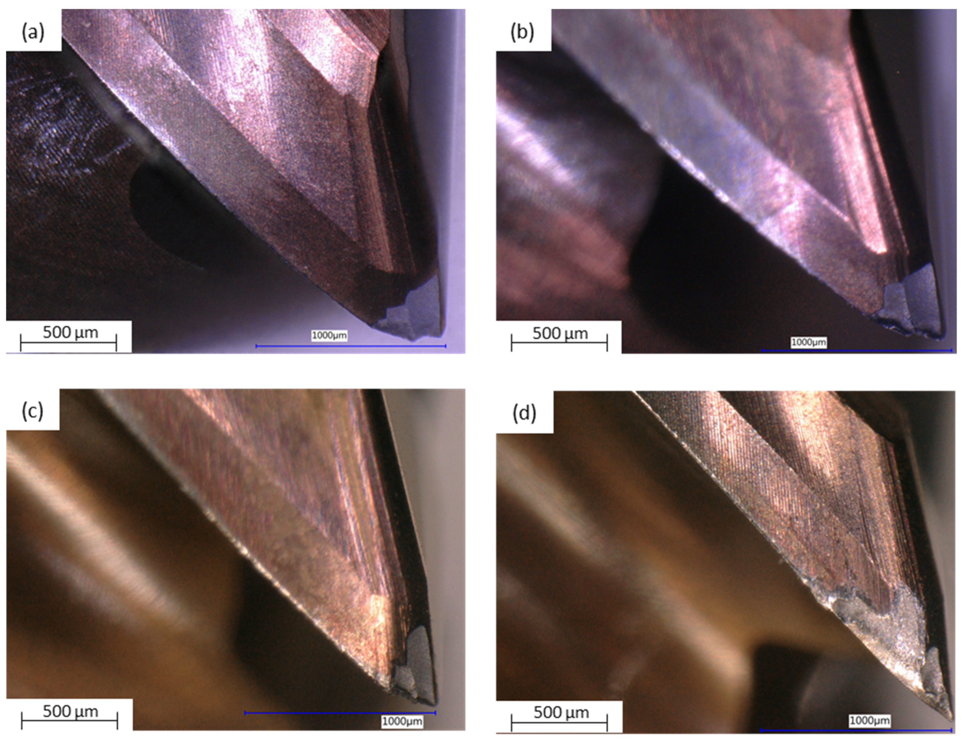
  • Tool wear mechanisms: tool wear during the milling of WAAM parts is dominated by an abrasive mechanism, with break-outs at the cutting edge corner observed frequently (Figure 7).
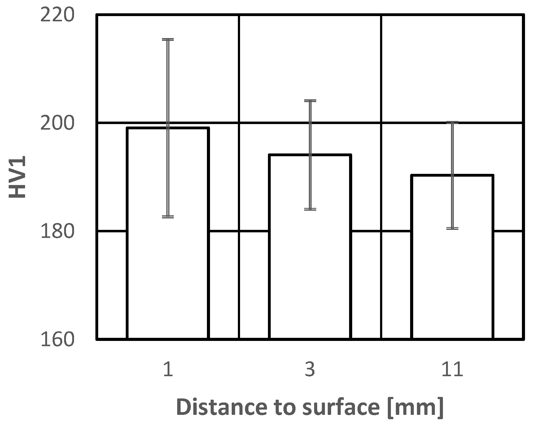
  • Bending moments: Bending moments during the milling of the surface layer are lower, attributed to reduced material removal compared to solid material milling. The higher tool wear on the surface layer suggests a higher hardness compared to the solid layer below (Figure 7).

Author Contributions

Conceptualization, A.P., R.H. and F.S.; methodology, A.P., R.H. and F.S.; software, K.S.; validation, A.P., R.H. and F.S.; formal analysis, K.S., M.A. and D.K.; investigation, K.S., M.A. and D.K.; resources, K.S., M.A. and D.K.; data curation, K.S., A.P., R.H. and F.S.; writing—original draft preparation, K.S. and A.P.; writing—review and editing, A.P. and F.S.; visualization, K.S.; supervision, R.H., F.S. and A.P.; project administration, F.S. and R.H.; funding acquisition, R.H., F.S. and A.P. All authors have read and agreed to the published version of the manuscript.

Funding

This research received no external funding.

Data Availability Statement

Data are contained within the article.

Conflicts of Interest

The authors declare no conflicts of interest.

References

  1. Gebhardt, A. Additive Fertigungsverfahren: Additive Manufacturing und 3D-Drucken für Prototyping-Tooling-Produktion; Carl Hanser Verlag GmbH & Company KG: München, Geramny, 2017; ISBN 9783446452367. [Google Scholar]
  2. Zhou, K. Additive Manufacturing Technology: Design, Optimization, and Modeling; Wiley: Hoboken, NJ, USA, 2022; ISBN 9783527833924. [Google Scholar]
  3. Bhate, D. Design for Additive Manufacturing: Concepts and Considerations for the Aerospace Industry; SAE International: Warrendale, PA, USA, 2018; ISBN 9780768091502. [Google Scholar]
  4. Rodrigues, T.A.; Duarte, V.; Miranda, R.M.; Santos, T.G.; Oliveira, J.P. Current Status and Perspectives on Wire and Arc Additive Manufacturing (WAAM). Materials 2019, 12, 1121. [Google Scholar] [CrossRef] [PubMed]
  5. Huang, Q.; Ge, J.; Wang, Y.; Bao, J.; He, S.; Zhang, Z.; Zhang, L. Characterization of the Anisotropy in the Microstructure and Mechanical Properties of Laser Powder Bed Fusion Ti6Al4V Alloys. Adv. Eng. Mater. 2023, 25, 2201156. [Google Scholar] [CrossRef]
  6. Gerbino, S.; Lanzotti, A.; Martorelli, M.; Buil, R.M.; Rizzi, C.; Roucoules, L. Advances on Mechanics, Design Engineering and Manufacturing IV: Proceedings of the International Joint Conference on Mechanics, Design Engineering & Advanced Manufacturing, JCM 2022, 1–3 June 2022, Ischia, Italy; Springer International Publishing: Berlin/Heidelberg, Germany, 2022; ISBN 9783031159282. [Google Scholar]
  7. Wahab Hashmi, A.; Singh Mali, H.; Meena, A. Improving the surface characteristics of additively manufactured parts: A review. Mater. Today Proc. 2023, 81, 723–738. [Google Scholar] [CrossRef]
  8. Gomes, M.C.; dos Santos, A.G.; de Oliveira, D.; Figueiredo, G.V.; Ribeiro, K.S.B.; de Los Rios, G.A.B.; Da Silva, M.B.; Coelho, R.T.; Hung, W.N.P. Micro-machining of additively manufactured metals: A review. Int. J. Adv. Manuf. Technol. 2022, 118, 2059–2078. [Google Scholar] [CrossRef]
  9. Hung, W. Postprocessing of Additively Manufactured Metal Parts. J. Mater. Eng. Perform. 2021, 30, 6439–6460. [Google Scholar] [CrossRef]
  10. Ji, H.; Gupta, M.K.; Song, Q.; Cai, W.; Zheng, T.; Zhao, Y.; Liu, Z.; Pimenov, D.Y. Microstructure and machinability evaluation in micro milling of selective laser melted Inconel 718 alloy. J. Mater. Res. Technol. 2021, 14, 348–362. [Google Scholar] [CrossRef]
  11. Bonaiti, G.; Parenti, P.; Annoni, M.; Kapoor, S. Micro-milling Machinability of DED Additive Titanium Ti-6Al-4V. Procedia Manuf. 2017, 10, 497–509. [Google Scholar] [CrossRef]
  12. Laue, R.; Colditz, P.; Möckel, M.; Awiszus, B. Study on the Milling of Additive Manufactured Components. Metals 2022, 12, 1167. [Google Scholar] [CrossRef]
  13. Chernovol, N.; Sharma, A.; Tjahjowidodo, T.; Lauwers, B.; van Rymenant, P. Machinability of wire and arc additive manufactured components. CIRP J. Manuf. Sci. Technol. 2021, 35, 379–389. [Google Scholar] [CrossRef]
  14. ASTM A240/A240M-17; Standard Specification for Chromium and Chromium-Nickel Stainless Steel Plate, Sheet, and Strip for Pressure Vessels and for General Applications. ASTM International: West Conshohocken, PA, USA, 2017. [CrossRef]
  15. ASTM B637-18; Specification for Precipitation-Hardening and Cold Worked Nickel Alloy Bars, Forgings, and Forging Stock for Moderate or High Temperature Service. ASTM International: West Conshohocken, PA, USA, 2023.
  16. ISO 8688-2:1989; Tool Life Testing in Milling—Part 2: End Milling. International Organization for Standardization: Geneva, Switzerland, 1989.
  17. Seco S.p.a. High Performance Machining Solid Carbide End Mills. Available online: https://www.secotools.com/article/p_02760834 (accessed on 12 July 2024).
  18. DIN EN ISO 6507-1:2018-07; Metallische Werkstoffe_-Härteprüfung nach Vickers_-Teil_1: Prüfverfahren (ISO_6507-1:2018). Deutsche Fassung EN_ISO_6507-1:2018. Beuth Verlag GmbH: Berlin, Germany, 2018.
  19. Czichos, H.; Habig, K.-H. Tribologie-Handbuch; Springer Fachmedien Wiesbaden: Wiesbaden, Germany, 2020; ISBN 978-3-658-29483-0. [Google Scholar]
  20. Palmeira Belotti, L.; van Dommelen, J.; Geers, M.; Goulas, C.; Ya, W.; Hoefnagels, J. Microstructural characterisation of thick-walled wire arc additively manufactured stainless steel. J. Mater. Process. Technol. 2022, 299, 117373. [Google Scholar] [CrossRef]
Figure 1. Test specimens: (a) 304H WAAM (BD, building direction), with the direction of milling paths (white arrows), (b) IN718 L-PBF, (c) CAD presentation of support structures’ geometry, (d) CAD presentation of half section A-A of (b), and (e) cross sections of solid material (black) and support structures (gray) of milling paths; dimensions are given in mm.
Applsci 14 06219 g001
Figure 2. Width of flank wear land on solid material and support structures of IN718 L-PBF on different tool travel paths.
Applsci 14 06219 g002
Figure 3. Width of flank wear land on full material and support structures of IN718 L-PBF at different cutting volumes.
Applsci 14 06219 g003
Figure 4. Wear on tools after milling of IN718 L-PBF as solid material (a) and support structure (b), for the same cutting volume of 4250 mm3.
Applsci 14 06219 g004
Figure 5. Maximal bending moments of first 5 milling paths of IN718 L-PBF specimen.
Applsci 14 06219 g005
Figure 6. Width of wear flank land for surface layer and full material of 304H WAAM specimen.
Applsci 14 06219 g006
Figure 7. Wear of tools after milling of 304H WAAM surface layers (a,b) and solid material (c,d), after 320 mm (a,c) and 3200 mm (b,d) tool travel paths.
Applsci 14 06219 g007
Figure 8. Characteristic total bending moments as a function of milling paths of 304H WAAM specimen.
Applsci 14 06219 g008
Figure 9. Hardness measurements depending on distance to 304H WAAM specimen surface.
Applsci 14 06219 g009
Table 1. Chemical composition of AISI 304H stainless steel and nickel superalloy IN718.
Chemical Composition [wt.%]
CMnPSSiCrNiNb + TaCoMoFe
304H [14]0.04–0.10≤2.00≤0.045≤0.030≤0.7518.0–20.08.0–10.5---Bal.
IN718 [15]≤0.08≤0.35≤0.015≤0.015≤0.3517.0–21.050.0–55.04.75–5.50≤1.02.8–3.3Bal.
Table 2. Tool parameters for milling tests.
Tool nr.Tool Diameter [mm]Number of Cutting TeethCorner RadiusHelix AngleTool Orthogonal ClearanceTool Orthogonal Rake AngleCoating
1640.535911TiAlN+ TiAl
2640.344914TiAlN
Disclaimer/Publisher’s Note: The statements, opinions and data contained in all publications are solely those of the individual author(s) and contributor(s) and not of MDPI and/or the editor(s). MDPI and/or the editor(s) disclaim responsibility for any injury to people or property resulting from any ideas, methods, instructions or products referred to in the content.

