Article

A Miniaturized Large-Field Fundus Optical System Based on Aspheric Imaging and Non-Coaxial Illumination

School of Information Science and Technology, Fudan University, Shanghai 200433, China
*
Author to whom correspondence should be addressed.
Appl. Sci. 2024, 14(14), 6216; https://doi.org/10.3390/app14146216
Submission received: 26 January 2024 / Revised: 14 April 2024 / Accepted: 29 May 2024 / Published: 17 July 2024

Abstract

:
Many diseases produce pathological changes in the fundus; analyzing the retinopathy of the fundus could help diagnose diseases in time. A fundus camera is a medical imaging device that specializes in taking fundus images to diagnose hypertension, coronary heart disease, diabetes, and others. The fundus optical imaging system is the core part of it. Nevertheless, the conventional fundus optical imaging system is large and not suitable for mobile examination and follow-up use. So, it has not been widely used in medical institutions. In this paper, a miniaturized fundus optical imaging system based on aspheric technology and non-coaxial illumination is proposed. The length of the imaging system is only 34.6   mm , the field of view is 50°, and the MTF curve is greater than 0.2 at 100 lp / mm , which can resolve the structure of 5   um . The illumination system adopts a non-coaxial annular array illumination structure to avoid occlusion of the imaging system. Our study effectively tackles the pressing predicament of fundus optical system miniaturization. This innovative paradigm harbors the potential to revolutionize fundus image data acquisition, propelling the field of fundus diagnosis forward and efficiently catering to crucial applications, improving the versatility of fundus examination, and providing technical support for the intelligent diagnosis system.

1. Introduction

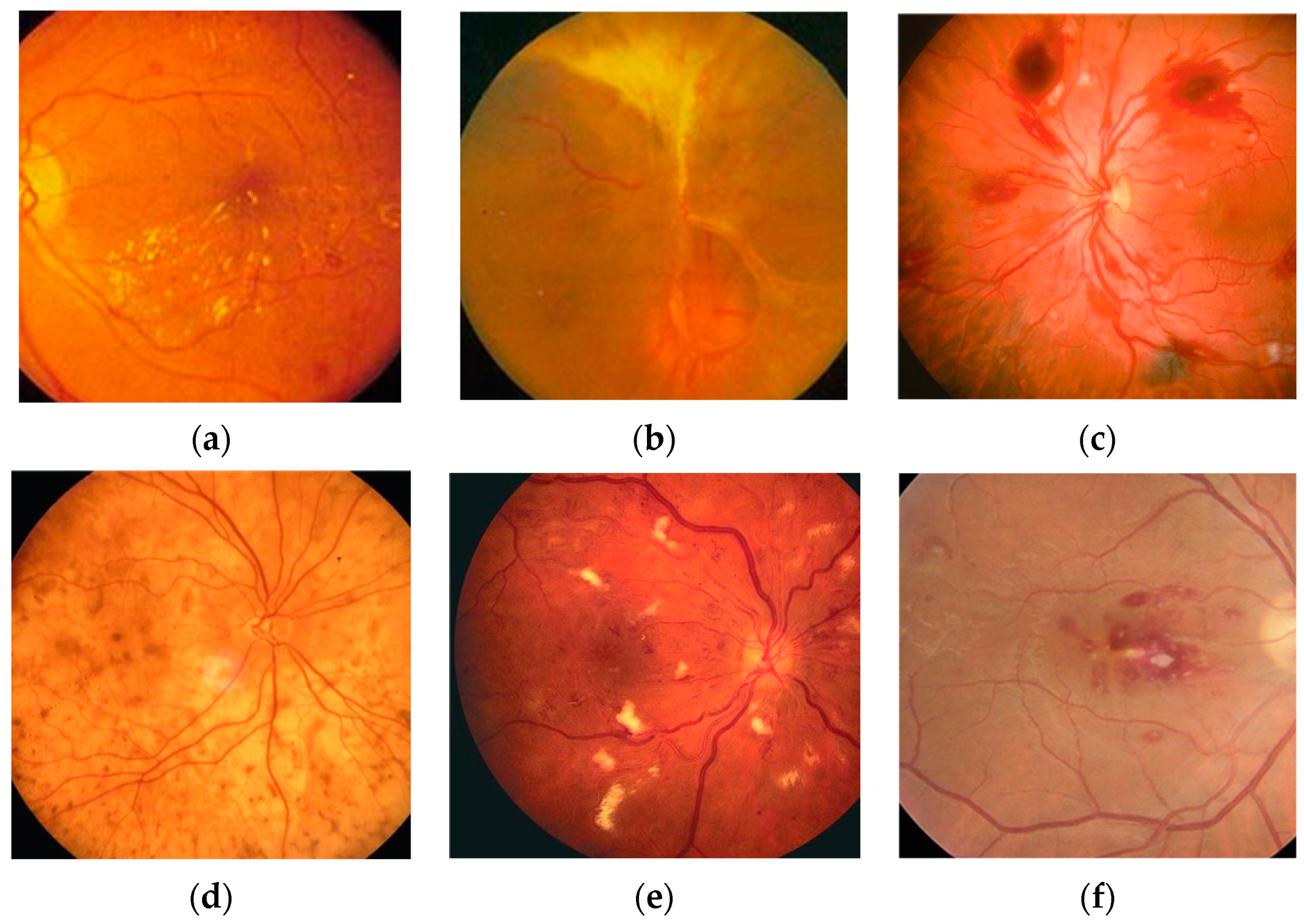
The eye is one of the most important organs of the human body, and the fundus, as an important part of the eye, has a large number of capillaries distributed on it, which are the only capillaries that can be directly observed non-invasively in the human body [1]. There is a close relationship between fundus health status and systemic diseases [2]. The fundus refers to the posterior tissues inside the eyeball, including structures such as the retina, macula, blood vessels, choroid, and optic nerve [3]. Medical research has shown that these structures are not only responsible for the formation and conduction of vision but also reflect the overall health of the body. For example, diabetes is a common systemic disease that causes retinal vasculopathy, which, in turn, leads to diabetic retinopathy [4]. High blood pressure can also cause changes in the blood vessels in the fundus, causing, for example, arteriosclerosis and retinal edema [4]. In addition, systemic diseases such as kidney disease, anemia, and leukemia can also be manifested through fundus lesions [5]. Many diseases in the human body will produce corresponding pathological changes to the retina of the fundus, and most patients have lesions in the fundus when the body has no obvious perception [6]. Some typical fundus lesion features are shown in Figure 1. The World Health Organization predicts that by 2030, the number of people with diabetic retinopathy will increase to 180.6 million, the number of people with age-related eye disease glaucoma will increase to 95.4 million, and the number of people with age-related macular degeneration will increase to 243.3 million [7]. Therefore, it is of great significance to make an early diagnosis of human health through fundus examination for the prevention and timely treatment of diseases.
With the continuous development of technology, innovation, and upgrades, ophthalmic medical devices are also being updated, in which fundus cameras are specially used to capture fundus images, gradually replacing traditional ophthalmoscopy methods. Fundus cameras use a special imaging and illumination system to clearly capture the structures behind the eyeball, including the vitreous, retina, choroid, and optic nerve [8], providing objective fundus images, helping doctors observe changes in fundus lesions, and providing ophthalmologists with a more accurate and comprehensive diagnosis basis. Secondly, fundus cameras can also be used to compare the effects of treatments, evaluating the effectiveness of treatments by observing changes in fundus images. At present, desktop fundus cameras can obtain good quality fundus images and shorten the time of consultation, but there are also some disadvantages that cannot be ignored, such as the high price of equipment, high acquisition and maintenance costs, the need for them to be operated by doctors, and the requirement of extra training and guidancefor initial purchase. In addition, due to the complexity of the optical system and the large and heavy equipment, the camera is not suitable for mobile examination and follow-up use. It has not yet been widely used in all medical institutions, and only some large hospitals or specialized ophthalmic medical institutions can introduce and use such systems, which has high limitations.
So, the main challenges in fundus camera design include the following:
(1) Optical design: The optical design of the fundus camera is key, and needs to ensure that the camera can capture high-quality, high-resolution fundus images. Factors to consider when designing include the wavelength, intensity, and optimization of the optical path of the light source. At the same time, due to the physiological structure and optical properties of the human eye, it is also necessary to ensure that the optical system is safe for the human eye.
(2) Image processing: The processing of fundus images is another important challenge in fundus camera design. Fundus images are often affected by various factors, so advanced image processing technology is required to improve image quality and the visibility and identification accuracy of lesion areas.
(3) System integration and miniaturization: With the development of technology, people have put forward higher requirements for the portability and ease of use of fundus cameras. Integrating high-precision optics, image acquisition and processing systems, light source systems, and other auxiliary functions into a small, lightweight device is a challenging task.
(4) Cost control: Cost control also needs to be considered while ensuring the performance of the equipment. Core components such as high-precision optical components and image processing chips are often costly, and how to reduce costs while ensuring performance is a practical challenge in fundus camera design.
Jiang Jian-yu et al. designed a 39° field of view of visible light non-mydriasis fundus camera optical system, which resolved the 10 μm structure of the fundus [7] and eliminated the stray light caused by the surface reflection of the omental objective lens group by polarization. The fundus retina illumination was uniform [7] but the imaging system was too long, reaching 265 mm. WANG Xiao-heng et al. designed a 40° field of view dual-light source fundus camera optical system [9], where visible light was used to shoot retinal images, near-infrared light was used for observation, the beamsplitter of visible light transmission and infrared light reflection were used to realize the dual-light source common beam path design, and corneal stray light was suppressed through the ring light source. The imaging system was 228 mm, so the length was still long, and the final design result was still relatively complex. In 2019, Diego Palacions et al. from the University of Miami in the United States [9] developed a handheld fundus camera based on Shumei Pai and implanted the Linux operating system and OpenCV library into the system. Four fundus images with a field of view angle of 10° were stitched together to obtain images with a field of view of 16° [10]. However, it was easy to lose the details of the fundus in the stitching of the image, the composite image could be distorted, and the proportion of each tissue could not be truly reflected.
In this context, our research presents a non-coaxial annular array illumination structure using aspherical lenses to reduce the total length of the system. This pioneering approach was designed to make the optical system compact. Our study was dedicated to facilitating the miniaturization of fundus cameras to match with components with different functions to realize the integration of functions and solve the problem of difficult and large volumes of stray light suppression in the traditional fundus optical system. We firmly anticipate that our contributions will propel advancements in the field, providing more detailed and accurate images tailored to practical applications.
The main contributions of this work are summarized as follows:
(1) Based on the actual light source size, diaphragm size, image quality requirements, and object resolution accuracy [11], we present a lens combination of aspheric and spherical lenses to image the human eye that has a field of view angle of 50° and a total imaging length of 34.6 mm, realizing miniaturization and a large field of view. The miniaturized design is easy to use in many settings, the large field of view effectively avoids the shadow caused by image stitching, and the high resolution means that the physiological features of the fundus can be clearly displayed, meeting the need for high accuracy in lesion identification and classification.
(2) In order to achieve the acquisition of high-resolution clear images, the fundus illumination system was designed to assist in the design. Point light sources and four illumination arrays were used to meet the fundus illumination height and the working distance of the illumination system, achieving a uniform illumination of the fundus so that the fundus blood vessels, optic disc, and lesions could be accurately displayed.
(3) To approach the practical application more accurately, our light resources employed the solar spectrum LED with low blue light, high green light, and high CRI, which reduced blue light damage to the human eye, improved the contrast of the fundus image, and restored the true color of the object more accurately, thus being more suitable for fundus lighting.

2. Methods and Design

In this section, we aim to elaborate on the design of the imaging and illumination system, which were the core parts of this study.

2.1. Overall Design of the Fundus Optical System

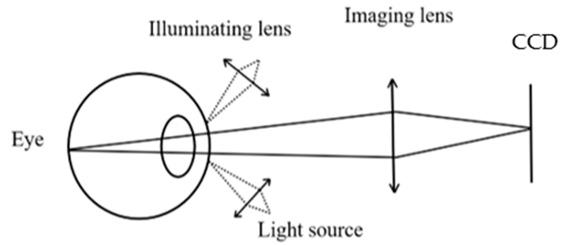
In this section, we first clarify the function and desired purpose of each part. The lighting system is mainly to illuminate the fundus area [12], introduce suitable light into the fundus, and cause the fundus to produce reflected light to obtain an image with sufficient contrast and clarity when shooting. The imaging system is mainly used to gather the reflected light from the fundus and clearly image the actual appearance of the fundus on the sensing component of the camera. The imaging system and illumination system need to work together to ensure the clarity and accuracy of the fundus image.
Second, we identify the inadequacy of traditional imaging. The optical architecture of the traditional fundus imaging system is complex, including a condenser, illumination diaphragm, relay lens group, hollow mirror, omentum objective [13], etc. The objective lens is divided into an eyepiece objective near the human eye and an imaging objective near the negative; the two sets of objectives make the total length of the system longer and the illumination system mostly adopts the coaxial illumination method, but, due to the common light path of the illumination system and the imaging system [14], it is difficult to suppress stray light caused by the cornea and omentum objective lens group of the human eye.
On this basis, by establishing a model of fundus imaging field of view and non-coaxial annular array illumination, the design for the illumination and imaging of a miniaturized and large-field fundus system is proposed. The structure we designed is shown in Figure 2. The human eye is a very sophisticated and complex optical imaging system; to make the design more in line with the application of practical medicine, the analysis is carried out in combination with an eye model.

2.2. Design of the Fundus Imaging System

This subsection will elaborate on the optimal design of the human eye model, imaging system parameters, and aspheric lens design.

2.2.1. Eye Model

The human eye is a very sophisticated and complex optical imaging system [15], and the design of the fundus optical system needed be carried out on the basis of conforming to the optical characteristics of human eyes. The optical system of the eye mainly includes the cornea, anterior chamber, lens, vitreous, and retina, and external light is imaged on the retina through the previous optical element in turn [16]. The power of light is provided by the cornea and the lens, so, when building the eye model, these two parts were mainly simulated. The cornea had a higher diopter and resembled a convex lens in an optical lens, and the lens was a biconvex structure that resembled a biconvex optical lens. Figure 3a is the standard eye model. The refractive index of the lens used in the standard eye model was uniform. The axial length was simplified to 24.0 mm, the retinal radius was simplified to 11.0 mm, and the anterior surface of the relaxed lens was simplified to a spherical surface with a radius of 10.0 mm [17].
However, the posterior surface of the lens was not flat and was approximately a parabola. This was a key factor in controlling off-axis aberration. Figure 3b is a more accurate model of the eye. Fine-tuning the conic coefficient on the posterior surface of the lens instead of the real-world refractive index gradient could compensate for the lower refractive index in the midline of the eye and reduce the time for ray tracing in optimized and non-sequential modes. The cone coefficient of the lens was set to 3 and the cone coefficient of the cornea was set to −0.3. The simulation in ZEMAX and the specific parameters and materials are shown in Table 1. The accurate human eye model brought the design of the imaging system proposed in this paper more in line with the requirements of the real environment and improved the accuracy of the imaging system.

2.2.2. Aspheric Lens Design

Considering the practicalities, the design adopted a single lens group, which had a simple structure, could achieve a compact design, and eliminated some of the aberrations of the human eye and the main aberration of the system. It could also avoid manufacturing defects as it is easier to accurately process lenses that meet requirements.
In the design, the full field of view was 50°. A large field of view would cause the fundus imaging to exceed the ideal range of the paraxial axis [18], which would inevitably increase the difficulty of aberration correction of the edge field of view of the system.
When the incident height of the ray on an aspheric surface is h and the casting height of the auxiliary rays is h z , the primary aberration coefficient [15] is as follows. In Equation (1), Δ S I , Δ S II , Δ S I V , and Δ S V are spherical aberration, coma, astigmatism, field curvature, and distortion. n is the object space refractive index, n is the image space refractive index, r is the radius of curvature, and b is the distance of the ray from the focal point of the optical axis to the aspheric surface. It can be seen that the aberration related to the field of view such as spherical aberration and comet changes due to the surface shape; on the contrary, we could improve the ability of the system to correct the aberration and simplify the system optical path by introducing the aspheric surface type.
Δ S I = n n b r 3 h 4 Δ S II = Δ S I h z h Δ S I I I = Δ S I h z h 2 Δ S I V = 0 Δ S V = Δ S I h z h 3
The general rotationally symmetric aspheric expression is as follows in Equation (2), where   k is the coefficient of the conic curve, c is the basic curvature of the vertex,   r is the radial coordinate of the perpendicular optical axis [15], and a 2 , a 4 ,   and   a 6 are the higher-order coefficients of the aspheric equation.
Z r = c r 2 1 + 1 1 + k c 2 r 2 + a 2 r 2 + a 4 r 4 + a 6 r 6 +
More optimization variables were introduced through aspheric surfaces, providing more freedom for the system design. So, the aspheric surface can reduce the aberration of the edge field of view. The ability of one aspheric surface to correct aberrations was equivalent to that of multiple spheres, which not only reduced the size and weight of the optical system but also achieved high resolution at large fields of view.

2.2.3. Imaging System Parameter

In order to miniaturize the fundus optical system, the total length of the system was limited in 50 mm . The pupil of the human eye was used as the aperture diaphragm of the imaging system, and the pupil diameter of the human eye is about 4 mm [19], so the entrance pupil diameter of the imaging system was set at 4mm. The field of view determined the size of the fundus imaging area, and the field of view of this system was 50°, considering the fundus viewing range. The imaging optical path used the visible wavelength band of 486 nm–656 nm for imaging [14]. The CCD sensor was selected as the receiver of the imaging system. The design indicators of the fundus imaging system are shown in Table 2.
As the pupil has the effect of limiting the amount of light entering the eye, it is usually used as the aperture diaphragm of the system in an optical system, and could be used as the aperture diaphragm of the imaging system in this system [16].
The field of view of the fundus camera refers to the range of fundus imaging, and the conversion formula of the fundus field of view and field angle is as follows:
h = f e y e × t a n ω
where h is the fundus half-field height, f e y e is the effective focal length of the human eye [15], and ω is the half-field angle, as shown in Figure 4.The effective focal length of the eye mask type in this design was 9.6   mm , the half-field angle was 25°, and the half-field height was 4.47 mm .
Combined with the eye model, the imaging group used a combination of spherical lens and aspheric lens [20], which was matched to a CCD with a pixel size of 5 μ m × 5 μ m and required a resolution of a 5 μ m retinal structure. From N = 1000 / 2 a ( N is the limit resolution, α is the pixel size), we can see that the ultimate resolution of the imaging system was 100   lp / mm . From φ = 1.22 λ D ( φ is the ratio of the pixel size d to the focal length f of the optical system, D is the diameter of the entrance pupil, and     λ is the center wavelength), the diffraction-limiting aperture value was 4.8. The two-dimensional structure is shown in Figure 5. The imaging system uses four single lenses to complete the design, of which two were aspherical lenses. The structure was simple, the total length of the system was greatly shortened, and the total length was only 34.6 mm, so the compact design was realized. The imaging lens group was a combination of positive and negative lenses and aspheric lenses, which eliminated some of the eye differences and the main aberrations of the system. The distance between the sensor and the camera port was about 10 mm , and the back intercept of the imaging system was 18   mm , meeting the requirements. Lens data of imaging system are shown in Table 3.

2.3. Design of the Fundus Illumination System

This subsection mainly covers the selection of the illumination source, theoretical calculation, and the design of the lighting arrays.

2.3.1. Illumination Source Selection and Theoretical Calculation

The human eye does not emit light, so it was necessary to choose a light source with the appropriate wavelength band. Figure 6a shows the spectral transmittance curve jointly studied by the U.S. Department of Industry and Hygiene, the University of Michigan, and the U.S. Department of Ophthalmology [21]. The four curves in the figure represent the spectral transmittance of different wavelengths of light through the anterior chamber, lens, vitreous, and retina. The wavelength is in the range of 450 to 800 nm and the transmittance of each tissue is above 75%.
Since the fundus tissue has a low effective reflectance of 0.1–0.001%, it is necessary to increase the irradiance of the illumination light in order to obtain a strong fundus-reflected light; the longer the wavelength of the incident light, the higher the reflectivity of the fundus tissue. It has a reflectivity of about 2% for yellow-green light at a wavelength of 550 nm and a reflectance of more than 10% for near-infrared light at 750 nm [12]. The reflectivity is relatively high, making it easier to obtain retinal images. However, the results of clinical medical testing showed that the resolution of fundus imaging is different under different wavebands. The design and development of a new fundus camera [12] by Li Can of the University of Chinese Academy of Sciences showed the results of fundus hyperspectral imaging, as shown in Figure 6b, from which it can be seen that compared with the near-infrared band, the resolution of fundus imaging images under visible light is higher. Therefore, in this study, visible light was chosen as the source of illumination.
Figure 7a shows the spectrum of a white LED light source. Figure 7b shows the spectrum of full-spectrum white LED. White LED with high blue light will cause some damage to the human eye. Full-spectrum white LED has a more continuous and uniform spectral distribution, which can provide a more natural lighting effect, and the color rendering index is higher, but the blue light is still high and the red light is higher.
The solar spectrum LED with low blue light and high CRI reduces blue light damage to the human eye and is more suitable for fundus lighting. In addition, the reflection ratio of the fundus to green light is high and the high proportion of green light will improve the contrast of the fundus image, which can more accurately restore the true color of the object. Therefore, a violet light excited the solar spectrum LED light source for fundus illumination.
Referring to the provisions of GB/T 7247.9-2016 “Safety of Laser Products—Part 9: Maximum Allowable Exposure of Incoherent Optical Radiation” [22] on the maximum allowable amount of irradiation that can be allowed by the human eye, the following formula was adopted [12]:
L m a x = 1 × 10 6 t W / m 2 · s r
t is the irradiation time, W / m 2 · s r   is the unit of radiance, and s r is the unit of solid angle.
Assuming illumination time t = 1 s, the maximum brightness of the LED can be calculated as L m a x = 10 6 W / m 2 · s r .
Knowing the maximum brightness perceived by the eye, the maximum power of the light source P m a x can be calculated from Equation (5):
P m a x = L m a x · A f u n d u s · Ω s o u r c e / η
L m a x is the maximum brightness of the light source, A f u n d u s is the illumination area of the light source in the fundus, Ω source is the solid angle of the illuminated beam, and η is the radiation efficiency of the light source [23].
The fundus illumination area was about 300 mm 2 = 0.0003 m 2 , the beam solid angle was about 0.6 s r , and the radiation efficiency of the LED was about 0.3, so P m a x = 10 6 × 0.003 × 0.6 / 0.3 = 600   w .
In order to ensure the safety of human eyes, when selecting a light source, its power should be within 1/100~1/10 of the maximum allowable power [23]. The solar spectrum LED met these requirements.
Topology shows that the condition of mapping region A to region B and the boundary condition of mapping the boundary of region A to region B are sufficient and necessary conditions for each other. When the mapping is continuous, the edge rays of the light source must reach the edge of the target surface through the elements of the optical system. If the edge rays are already mapped within the required range, the other rays must be within the target spot. Based on the principle of edge light, the design reduced the consideration of other rays and simplified the calculation of optical systems with complex light distributions.
The light source of the fundus illumination system is an LED light source, and its light-emitting surface is a certain size. The refractive index of the space where the light source is located is n, the area of the luminous surface is d A , and the solid angle of the beam is d Ω [23]. The angle between the normal of the luminescent surface element and the center line of the solid angle is θ, and the spatial properties of the beam of the light source can be described by the optical expansion, and the mathematical form of the optical expansion is given by Equation (6):
E = n 2 cos θ d A d Ω
Assuming that the light source is an ideal point light source, in the direct coordinate system x y z , the light source is located at the origin of the coordinate system, the optical axis is in the positive direction of the z-axis [23], the direction of light propagation is expressed by the angle   θ ,   φ , the angle between the ray and the positive direction of the z-axis is θ , the angle between the projection of the ray on the x y z plane and the positive direction of the x-axis is φ , and the luminous intensity of the light source is I s θ , φ . Then, the luminous flux of the light source is given by Equation (7):
ϕ s = I s θ , φ d Ω
The illuminance of the light source reaching the fundus is E x , y , and this value is related to the coordinates   x . y . Then, the amount of light in the fundus can be expressed as:
ϕ f = E x , y d A
Then ϕ s = ϕ f and luminous flux is conserved, which guarantees the efficiency of the lighting system [22].

2.3.2. Non-Coaxial Lighting System Design

The illumination part was composed of a light source and a condenser lens and adopted a non-coaxial annular array illumination structure to achieve the suppression of corneal stray light by controlling the range of the pupil spot, the divergence angle of the light source, and the angle of incident light of the light source [22], which effectively avoided the stray light generated by the residual reflection of the optical element.
In the human eye, the cornea has a high reflectivity of 1.37, and the light incident on the cornea from the front will inevitably produce ghost images [22], which will affect the image quality. As shown in Figure 8, the critical angle of the incident ray was 30 degrees, according to the simulation. The corneal margin incident illumination is shown in Figure 9. In order to solve this problem, non-coaxial surround lighting was used to improve space utilization and avoid occlusion of the imaging system. Four LED light sources were evenly distributed 360° to form a ring, and the light source illuminated the fundus through the lens and spread the entire pupil, reducing the illumination light received on the cornea, thus preventing the ghost image caused by its reflection. The design results are shown in Figure 10.

3. Analysis and Discussion

3.1. Imaging System Analysis

The image quality analysis evaluation index of Zemax is mainly Spot Diagram, Field Curvature Distortion, and MTF Curves [24].
The object–image relationship of the optical system was as follows:
i u , v = o u , v h u M u u , v M v v d u d v
In Equations (2)–(4), o u , v is the pattern of the object, i u , v is the image square pattern, u , v and u , v are the Cartesian coordinates of the corresponding object plane and image plane, M u and M v are the lateral magnifications of the object, and h u M u u , v M v v   is the response of the system to the unit pulse u , v at δ u , v . Generally, only the similarity of the distribution of objects and images is considered, and the scale of objects and images is not considered, so it was assumed that M u = M v = 1. Therefore, Equation (9) could be simplified as follows:
i u , v = o u , v × h u , v
The integral value of the point image distribution function h u , v was normalized to obtain the point spread function of the fundus imaging system:
P S F u , v = h u , v / h u , v d u d v  
P S F u , v denotes the radiant power per unit area [12], for which Fourier transform was the optical transfer function of the fundus imaging system:
O T F r , s = P S F u , v e i 2 π r u + s v d u d v
O T F r , s   is a complex function. Therefore, it can be written as follows:
O T F r , s = M T F r , s e i P T F r , s
Among them, the modulo MTF(r,s) of the optical transfer function was the amplitude transfer function, which represented the modulation attenuation of the transfer harmonic component of the fundus imaging system, which could fully reflect all the effects of aberration except distortion, and was an important evaluation index. Figure 11 shows the MTF diagram of the imaging system; the vertical axis is the modulus value of the optical transfer function, which represents the contrast ratio, and the maximum value is 1 [24]. The horizontal axis represents the spatial frequency of the system in lp / mm . The larger the area enclosed by the MTF curve and the coordinate axis, the better the quality of the optical system and the clearer the image. The different colors in Figure 11 represent different field-of-view curves, and the dashed and solid lines represent the sagittal and meridian directions.
According to pharmaceutical industry standard YY0634-2008 “Ophthalmic Instruments Fundus Camera” [25], in order to obtain better imaging quality, the general cut-off frequency MTF of the system should be greater than 0.2 [26].
As shown in the figure, the MTF modulus values of the whole field of view at 100 lp / mm were all above 0.2, which shows that the imaging system in this study could resolve the structural unit with a diameter of 5 um on the fundus.
Figure 12 is the Spot Diagram and Field Curvature Distortion of the imaging system; the Spot Diagram gives the root mean square (RMS) radius value and geometric (GEO) radius of each field of view. The smaller the value, the better the imaging quality. It is generally believed that less than 6 µm can be used to image fundus lesions clearly. It can be seen that the RMS radius of the diffuse spot in this imaging system was less than 3   um and the maximum RMS radius was 2.148 µ m , which meant that fundus lesions could be clearly imaged. The field curvature and distortion diagram give the change of the position of the fine beam image point leaving the image plane in different fields of view; the field curvature diagram is the thin beam meridian and arc sagittal field curvature of three wavelengths. The whole field curvature of the system was less than 0.2 mm and the distortion was less than 10% to ensure that the final fundus image was not distorted.

3.2. Illumination System Analysis

Figure 13 shows the relative irradiance of each field of view and incoherent irradiance. Relative illumination is the ratio of the illuminance at any point on the sensor to the maximum illuminance in the field of view; RI is proportional to cos4 (semi-FOV) [26], which is related to field of view, vignetting, distortion, and transmittance. Vignetting causes the image to have high brightness in the center and darkness around it, commonly known as vignetting, and can also cause color distortion and low illumination. When the half-field angle semi-FOV = 30°, the theoretical RI < 56%, and the RI that can be distinguished by the human eye is about 50%, so the basic requirement of RI is greater than 50% [26]. The RI of each field of view in this design was much higher than 63%, so the system met the requirements and did not produce vignetting.
After the non-sequential conversion was completed, the light source and illuminance detector were inserted into the illumination optical path, the light source power was set to 1 W, and 10,000 traces were traced. The light rays arriving at the illuminance detector were traced and analyzed, and the fundus illuminance distribution curve of Figure 13 was obtained, and it can be seen that the diameter of the fundus illumination area was greater than 12 mm, which met the illumination area range required by the imaging field of view.
U = 1 P c e n t e r P 85 % P m a x
The lighting uniformity of this study reached 86.3%, which met the requirements of use. In addition, according to ISO 15004-2.2 standard [27] ophthalmic optical instrument guidance [28], in the visible light band, in order to avoid thermal damage to the human eye, the irradiance needs to be less than 706 mW/cm2. The simulation results show that the maximum irradiance in this study was 520 W/cm2; when considering the attenuation effect of lenses on light, the actual irradiance reaching the fundus will be as low as 130 W/cm2, so it will not cause thermal damage to the human eye.

3.3. Extended Analysis

Due to the large field of view of the design, in order to evaluate the distortion of the lens more accurately, we conducted an extended image analysis, as shown in Figure 14. The image quality was simulated by the convolution of the original image and the spread function of the lens points, and the effects of diffraction, geometric aberration, distortion, relative illumination, polarization, and image position orientation were analyzed. In the network convolution setting, the pupil sampling and image plane sampling were both 128 × 128 and the number of points of PSY-X and PSF-Y was set to 3, which ensured effective and efficient analysis. The reference master ray displayed the in situ map as a simulation map [28] without much distortion.

4. Experiment

In this chapter, we describe the experimental system that simulated our design. First, the feasibility of physical processing was assessed through tolerance analysis and then the system was built using the processed physical objects to verify the design of this paper.

4.1. Experimental Feasibility

Tolerance analysis was performed for the above layout, starting with the eyepiece group, and a total of 6 lens sensitivities were analyzed [29]. Sensitivity variables included thickness, center shift, tilt, displacement, surface shape, refractive index, dispersion coefficient, etc., as shown in the Table 4.
After 1000 cycles of software, the MC algorithm was executed and the sensitivity distribution and image quality influence could be roughly estimated. The results of the analysis is shown in Figure 15 and Figure 16.
Figure 15 shows that more than 80% could be concentrated in the >0.2@100 lp / mm , and the rest was distributed below 0.2. The edge field of view was particularly low, and the worst was >0.2@45 lp / mm . As shown in Figure 16, the tolerance of the distortion curve was excellent, all of which met the target requirements within 5% and 100%.
The yield of the field of view of the quantitative analysis center is shown in Table 5, and the yield that met the 0.2@100lp was more than 98%, which basically met the requirements of 3sigma [30].
The quantitative analysis of the yield of the 0.7 field of view is shown in Table 6, and the yield of the 0.2@100lp was more than 98%, which basically met the requirements of 3sigma.
The yield of the quantitative analysis edge field of view is shown in Table 7, and the yield that met the 0.2@100lp was more than 80%, which basically met the requirements of 1sigma.
In summary, the yield of 0.7F and below was high, and the MTF could basically meet the manufacturing requirements of 3sigma, and, beyond 0.7F, the MTF could meet the requirements of 1sigma [30]. The distortion had a very high yield in the whole field of view, almost reaching 100% of the requirements.

4.2. Experiment System Construction

As shown in Figure 17, we adjusted the eye model, the assembled imaging and illumination system, and the CCD to the same optical axis position and adjusted the distance. We connected the CCD to the display and directly transferred the captured picture to the display device. Experiments showed that fundus images of simulated eyes could be acquired. After experiments with the model eye, we tried to acquire images of the human eye, as shown in Figure 18.

5. Limitations

Although this study achieved some results in miniaturized large-field imaging, there are still some limitations, which may have a certain impact on the interpretation and generalization of the research results.
The eye model we considered was based on the standard human eye, but we needed to take into account that the visual acuity of different people is different, so this design is not suitable for a human eye with different refractions. In addition, we only acquired images and did not carry out subsequent image processing and analysis, which did not make the system more automated. In order for everyone to obtain a clear image with the camera and obtain the results of lesion analysis directly, here are some key design considerations for the future:
(1) Adjustable eyepiece: The camera’s eyepiece should have diopter adjustment, similar to the power adjustment of glasses. This can be achieved by setting a diopter dial or knob on the eyepiece, which the user can adjust according to their visual condition.
(2) Autofocus system: In addition to manually adjusting the diopter, the camera should also be equipped with an advanced autofocus system. The system quickly and accurately identifies the subject and automatically adjusts the focus as needed to ensure crisp images [31].
(3) Software design: In terms of software, the clarity of the image can be further improved through algorithm optimization. For example, image processing techniques can be utilized to correct image blurring due to diopter differences. After the image is collected, the image processing and analysis are automatically carried out, and the result is displayed to the user.
(4) Compatibility considerations: The camera may also consider compatibility with glasses or other vision aids. For example, special interfaces or accessories can be designed so that the user can wear glasses while using the camera.
6. Conclusions

In this paper, a miniaturized optical system for fundus based on aspherical imaging technology and non-coaxial was designed. The system had a large full field of view of 50° with a length of only 34.6   mm , and the MTF curve was greater than 0.2 at 100 lp / mm , which meant that it had high resolution and could clearly present fundus images. The illumination light path and imaging light paths were independently designed and solar spectrum LED was used as the light source [32], with a higher color rendering index than other light sources, which is conducive to obtaining high-contrast retinal images. The illumination part was composed of a light source and a condenser lens and adopted a non-coaxial annular array illumination structure. Four LED light sources were evenly distributed 360° to reduce the amount of illumination received on the cornea, effectively suppress stray light in the optical path, improve space utilization, and avoid obstruction to the imaging system.
The simulation results show that the small fundus optical system designed in this study has a compact structure, high imaging quality, and a large field of view. It can lay the foundation for the development of high-resolution, miniaturized, and large field-of-view fundus cameras and portable intelligent wearable devices and improve the universality and diagnostic efficiency of fundus examinations. At the same time, the state of the fundus is closely related to physical health; the design can also provide technical support for intelligent disease diagnosis and prediction systems. Ultimately, after collecting fundus images and processing them, the automatic diagnosis of fundus diseases and improved physical health can be achieved.

Author Contributions

Conceptualization, S.L. and A.G.; methodology, S.L.; validation, S.L. and J.W.; formal analysis, S.L.; investigation, Q.W.; resources, A.G.; writing—original draft preparation, S.L.; writing—review and editing, S.L.; supervision, A.G.; project administration, A.G.; funding acquisition, A.G. All authors have read and agreed to the published version of the manuscript.

Funding

This research received no external funding.

Institutional Review Board Statement

Not applicable.

Informed Consent Statement

Not applicable.

Data Availability Statement

The raw data supporting the conclusions of this article will be made available by the authors on request.

Acknowledgments

Thanks to all institutions or units that published the datasets. Relevant links and citations are indicated in the paper.

Conflicts of Interest

The authors declare no conflicts of interest.

References

  1. Wahab Sait, A.R. Artificial Intelligence-Driven Eye Disease Classification Model. Appl. Sci. 2023, 13, 11437. [Google Scholar] [CrossRef]
  2. Sebastian, A.; Elharrouss, O.; Al-Maadeed, S.; Almaadeed, N. A Survey on Diabetic Retinopathy Lesion Detection and Segmentation. Appl. Sci. 2023, 13, 5111. [Google Scholar] [CrossRef]
  3. Liu, Z.; Qiu, S.; Cai, H.; Wang, Y.; Chen, X. Enhancing Autofocus in Non-Mydriatic Fundus Photography: A Fast and Robust Approach with Adaptive Window and Path-Optimized Search. Appl. Sci. 2024, 14, 286. [Google Scholar] [CrossRef]
  4. Ehoog, E.A. Novel Fundus Camera Design; The University of Arizona: Tucson, AZ, USA, 2008; Volume 10. [Google Scholar]
  5. McGrory, S.; Cameron, J.R.; Pellegrini, E.; Warren, C.; Doubal, F.N.; Deary, I.J.; Dhillon, B.; Wardlaw, J.M.; Trucco, E.; MacGillivray, T.J. The application of retinal fundus camera imaging in dementia: A systematic review. Alzheimer’s Dement. Diagn. Assess. Dis. Monit. 2017, 6, 91–107. [Google Scholar] [CrossRef]
  6. Shaukat, N.; Amin, J.; Sharif, M.I.; Sharif, M.I.; Kadry, S.; Sevcik, L. Classification and Segmentation of Diabetic Retinopathy: A Systemic Review. Appl. Sci. 2023, 13, 3108. [Google Scholar] [CrossRef]
  7. Jiang, J.; Yang, B.; Wan, X.; Zhang, W.; Wei, X.; Zhang, J.; Huang, P. Optical system of portable pupil free eyeground camera with beacon. Opt. Technol. 2019, 45, 240–244. (In Chinese) [Google Scholar]
  8. Jang, J.; Zhang, Y.; Xie, H.; Gong, S.; Zhu, S.; Wu, S.; Li, Z. Deep learning-based automated grading of visual impairment in cataract patients using fundus images. High Technol. Lett. 2023, 29, 377–387. [Google Scholar]
  9. Wang, X.; Xue, Q. Optical design of large field hand-held non mydriatic fundus camera. J. Opt. 2017, 37, 246–253. (In Chinese) [Google Scholar]
  10. Wu, Y.; Guo, Z.; Yu, M.; Wnag, L.P. Optical System Design of Miniaturized Fundus Camera Based on Non-coaxial Array Illumination. Acta Photonica Sin. 2020, 49, 0822002. [Google Scholar]
  11. International Diabetes Federation. IDF Diabetes Atlas, 9th ed.; International Diabetes Federation: Brussels, Belgium, 2019. [Google Scholar]
  12. Li, C. Design and Development of a New Fundus Camera; Changchun Institute of Optics, Precision Machinery and Physics, Chinese Academy of Sciences: Changchun, China, 2014. (In Chinese) [Google Scholar]
  13. Ogagarue, E.R.; Lutsey, P.L.; Klein, R.; Klein, B.E.; Folsom, A.R. Association of ideal cardiovascular health metrics and retinal microvascular findings: The Atherosclerosis Risk in Communities Study. J. Am. Heart Assoc. 2013, 2, e000430. [Google Scholar] [CrossRef]
  14. Li, C.; Sun, Q.; Liu, Y.; Lu, X.; Wang, J.; Sun, J.X.; Liu, J.Z.; Qu, F. Design of uniform illumination and anti stray light interference of fundus camera. China Opt. Appl. Opt. 2010, 3, 363–368. (In Chinese) [Google Scholar]
  15. Huang, Y. Design of Near Infrared Fundus Camera; Nanjing University of technology: Nanjing, China, 2011; Volume 8. (In Chinese) [Google Scholar]
  16. Palmer, D.W.; Coppin, T.; Rana, K.; Dansereau, D.G.; Suheimat, M.; Maynard, M.; Atchison, D.A.; Roberts, J.; Crawford, R.; Jaiprakash, A. Glare-free retinal imaging using a portable light field fundus camera. Biomed. Opt. Express 2018, 9, 3178–3192. [Google Scholar] [CrossRef]
  17. DeHoog, E.; Schwiegerling, J. Optimal parameters for retinal illumination and imaging in fundus cameras. Appl. Opt. 2009, 47, 6769–6777. [Google Scholar] [CrossRef]
  18. Li, C.; Song, S.; Li, C.; Liu, Y.; Sun, Q. Optical system design of hand held fundus camera. Acta Opt. Sin. 2012, 32, 240–246. (In Chinese) [Google Scholar]
  19. Xu, L.; Pei, Y.C.; Wang, D.; Wu, Z. Mechanical method to reduce aberrations for a two-sided coating axisymmetric optical lens based on the specialized finite element method. Appl. Opt. 2024, 63, 429–436. [Google Scholar] [CrossRef] [PubMed]
  20. AlRowaily, M.H.; Arof, H.; Ibrahim, I. Luminosity and Contrast Adjustment of Fundus Images with Reflectance. Appl. Sci. 2023, 13, 3312. [Google Scholar] [CrossRef]
  21. Edward, A.; Boettner, J.; Reimer, W. Transmission of the Ocular Media. Investig. Ophthalmol. Vis. Sci. 1962, 1, 776–783. [Google Scholar]
  22. GB/T 7247.9-2016; AQSIQ, Standardization Administration of China. Safety of Laser Products—Part 9: Compilation of Maximum Permissible Exposure to Incoherent Optical Radiation. Standards Press of China: Beijing, China, 2017. (In Chinese)
  23. Yang, J.; Cheng, D.; Wang, Q. The design of optical system for a new large field of view defocusing fundus camera. Acta Opt. Sin. 2012, 32, 212–218. (In Chinese) [Google Scholar]
  24. Obayya, M.; Nemri, N.; Nour, M.K.; Al Duhayyim, M.; Mohsen, H.; Rizwanullah, M.; Sarwar Zamani, A.; Motwakel, A. Explainable Artificial Intelligence Enabled TeleOphthalmology for Diabetic Retinopathy Grading and Classification. Appl. Sci. 2022, 12, 8749. [Google Scholar] [CrossRef]
  25. YY0634-2008; Ophthalmic Instruments Fundus Camera. China Food and Drug Administration: Beijing, China, 2008.
  26. Cheng, S.Y. Design of Liquid Crystal Adaptive Optical System for Fundus Blood Vessel Imaging. Ph.D. Thesis, Changchun Institute of Optics, Fine Mechanics and Physics, Chinese Academy of Sciences, Changchun, China, 2010. (In Chinese). [Google Scholar]
  27. ISO 15004-2.2; Ophthalmic Instruments—Fundamental Requirements and Test Methods—Part 2: Light Hazard Protection. ISO: Geneva, Switzerland, 2007.
  28. Mujat, M.; Ferguson, R.D.; Patella, A.H.; Iftimia, N.; Lue, N.; Hammer, D.X. High resolution multimodal clinical ophthalmic imaging system. Opt. Express 2010, 18, 11607–11621. [Google Scholar] [CrossRef]
  29. Zawadzki, R.; Jones, S.; Olivier, S.; Zhao, M.; Bower, B.; Izatt, J.; Choi, S.; Laut, S.; Werner, J. Adaptive-optics optical coherence tomography for high-resolution and high-speed 3D retinal in vivo imaging. Opt. Express 2005, 13, 8532–8546. [Google Scholar] [CrossRef] [PubMed]
  30. Purbrick, R.M.; Izadi, S.; Gupta, A.; Chong, N.V. Comparison of optomap ultrawide-field imaging versus slit-lamp biomicroscopy for assessment of diabetic retinopathy in a real-life clinic. Clin. Ophthalmol. 2014, 8, 1413–1417. [Google Scholar] [CrossRef] [PubMed]
  31. Dehoog, E.; Schwiegerling, J. Fundus camera systems: A comparative analysis. Appl. Opt. 2009, 48, 221–228. [Google Scholar] [CrossRef] [PubMed]
  32. Vienola, K.V.; Holmes, J.A.; Glasso, Z.; Rossi, E.A. Head stabilization apparatus for high-resolution ophthalmic imaging. Appl. Opt. 2024, 63, 940–944. [Google Scholar] [CrossRef] [PubMed]
Figure 1. Typical fundus lesion features (images are collated and taken from the web page https://ophth.dxy.cn/article/501624, accessed on 2 January 2024). (a) Nonproliferative diabetic retinopathy (NPDR) with scattered hard exudates and small hemorrhagic spots around the macula. (b) Proliferative diabetic retinopathy with significant early vitreous hemorrhage. (c) Acute leukemia with a combination of flame hemorrhage, lint spots, and Roth spots. (d) Chronic leukemia with leopard-like changes due to choroidal infiltrate. (e) Stage III hypertensive retinopathy with arteriosclerotic changes, generalized coarctation, copper wires, scattered lint spots, and flame hemorrhages in the retinal arteries. (f) Infective endocarditis with central white hemorrhage in the fundus, known as Roth spots.
Applsci 14 06216 g001
Figure 2. Structure diagram of new fundus optical imaging system.
Applsci 14 06216 g002
Figure 3. Eye model. (a) Standard eye model. (b) Optimized eye model.
Applsci 14 06216 g003
Figure 4. Imaging field of view.
Applsci 14 06216 g004
Figure 5. Design results of the imaging system in Zemax. (a) Two-dimensional structure of the imaging system. (b) Three-dimensional structure of the imaging system.
Applsci 14 06216 g005
Figure 6. (a) Spectral transmittance of human eye tissues (the spectral transmittance curve jointly studied by the U.S. Department of Industry and Hygiene, the University of Michigan, and the U.S. Department of Ophthalmology in 1962). (b) Fundus hyperspectral imaging results [12].
Applsci 14 06216 g006
Figure 7. Spectral distribution of light sources. (a) White LED spectrum. (b) Full-spectrum white LED spectrum. (c) The solar spectrum LED’s spectral distribution and color coordinates.
Applsci 14 06216 g007
Figure 8. A ray optics model to predict the light path.
Applsci 14 06216 g008
Figure 9. Corneal margin incident illumination. (a) The incident light of the cornea in the critical state is (b) higher than the incident light in the critical state and (c) lower than the incident light in the critical state.
Applsci 14 06216 g009
Figure 10. Lighting system design results.
Applsci 14 06216 g010
Figure 11. MTF curve of the imaging system.
Applsci 14 06216 g011
Figure 12. Spot Diagram and distortion map of imaging system. (a) Spot Diagram. (b) Field Curvature Distortion.
Applsci 14 06216 g012
Figure 13. Relative illumination and incoherent irradiance.
Applsci 14 06216 g013
Figure 14. Extended geometric phase analysis.
Applsci 14 06216 g014
Figure 15. MTF curve after 1000 cycles of execution by the MC algorithm.
Applsci 14 06216 g015
Figure 16. Field curvature and distortion after 1000 cycles of execution by the MC algorithm.
Applsci 14 06216 g016
Figure 17. Experiment system.
Applsci 14 06216 g017
Figure 18. The experimental system used to acquire images.
Applsci 14 06216 g018
Table 1. Parameters of eye model.
No.Surface TypeRadiums/mmThickness/mmMaterialDiameterCone Coefficient
OBJ(RETINA)Standard11.00016.580VITREOUS11.0000.000
1(LENS)Standard6.0003.700LENS5.000−3.000
2Standard−10.0000.100AQUEOUS5.0000.000
STO(IRIS)StandardInfinity1.600AQUEOUS11.0000.000
4Standard−11.0001.500AQUEOUS11.0000.000
5(CORNEA)Standard−6.7000.520CORNEA6.000−0.300
6Standard−7.8002 6.000−0.500
Table 2. Design indicators of fundus imaging system.
ParameterValue
Pupil diameter4 mm
Wavelength486 nm–656 nm
Full field of view50°
Object resolution Distinguish   the   fundus   5   μ m
Total length<50 mm
Table 3. Lens data of imaging system.
No.Surface TypeRadiums/mmThickness/mmMaterialDiameterCone Coefficient
1Even Asphere29.7675.678D-FK6110.015−5.388
2Even Asphere−18.7970.099 10.0150.296
3Standard53.3403.842D-ZPK510.1970.000
4Standard−28.6670.100 10.1970.000
5Standard−31.4409.774H-ZF6210.1620.000
6Standard23.1920.100 10.1620.000
7Even Asphere12.75010.001H-ZF73GT12.717−0.935
8Even Asphere13.3824.999 12.7170.543
IMAStandardInfinity- 10.7400.000
Table 4. Sensitivity variable parameters.
Sensitivity VariablesParameter
Thickness0.03
Center deviation3′
Incline 3′
Displacement 0.05
Face N5
Refractive index0.001
Dispersion coefficient0.5%
Table 5. Field of view yield.
PossibilityMTF
980.44153281
900.45462481
800.45859166
500.46616629
200.47166991
100.47352257
Table 6. The 0.7 field of view yield.
PossibilityMTF
980.21265461
900.23985155
800.25139236
500.26778926
200.28587413
100.30042033
Table 7. Edge field of view yield.
PossibilityMTF
980.14558791
900.18522674
800.20972288
500.28115658
200.34524594
100.36088431
Disclaimer/Publisher’s Note: The statements, opinions and data contained in all publications are solely those of the individual author(s) and contributor(s) and not of MDPI and/or the editor(s). MDPI and/or the editor(s) disclaim responsibility for any injury to people or property resulting from any ideas, methods, instructions or products referred to in the content.