
Concept of Thermal Shrinkage-Resistant Railroad Rail for Use in Continuous Welded Rail Track


Abstract
Highlights
- The paper concerns the possibility of using an innovative railway rail structure in a contactless track:
- The correct operation of CWR track, due to the occurrence of additional thermal stresses with a value dependent on changes in rail temperature, requires a systematic diagnosis of its condition;
- The paper presents the research of longitudinal force load tests for a classic rail and for two cases of an innovative railway rail solution.
- The research presented in the paper shows that:
- The proposed proprietary design of the rail used for the railroad track can enable the reduction in the longitudinal force occurring as a result of high ambient temperatures;
- The use of an innovative rail conception will allow for less steel consumption, which means less emissions into the atmosphere during its production (lower carbon footprint).
Abstract
1. Introduction
- α—thermal expansion coefficient of the rail steel [1/°C];
- E—Young modulus of steel [MPa];
- ΔTp—temperature difference in the rail about the neutral temperature (the temperature at which there is no thermal stress in the rail) [°C].
- A—rail cross-section area [m2];
- Other symbols are defined as in Formula (1).
2. Literature Review
3. Concept of Thermal Shrinkage-Resistant Railroad Rail
4. Research Method
4.1. Simulation Studies
4.2. Material Model
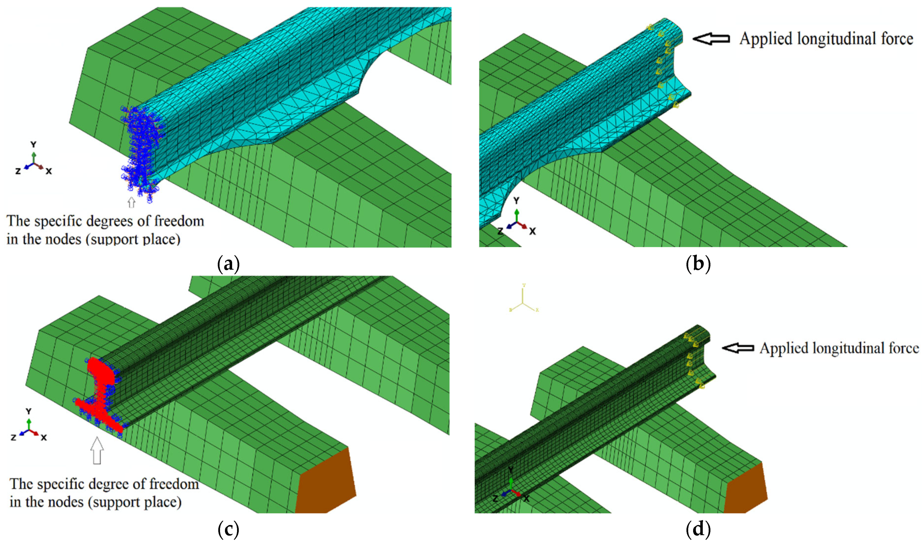
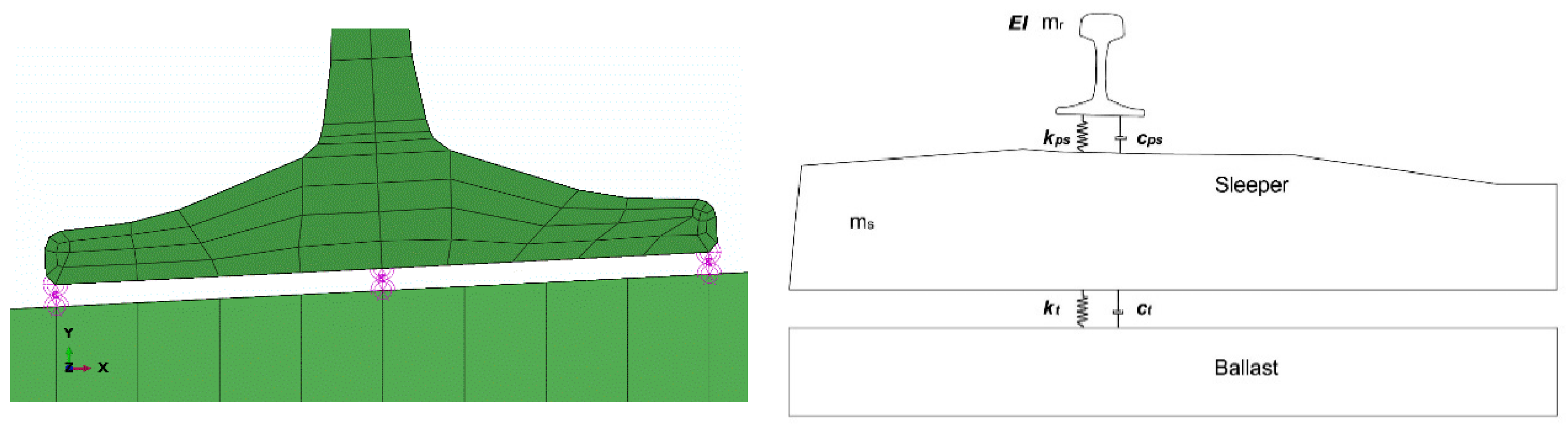
4.3. Numerical Model of the Track–Boundary Conditions and Loading
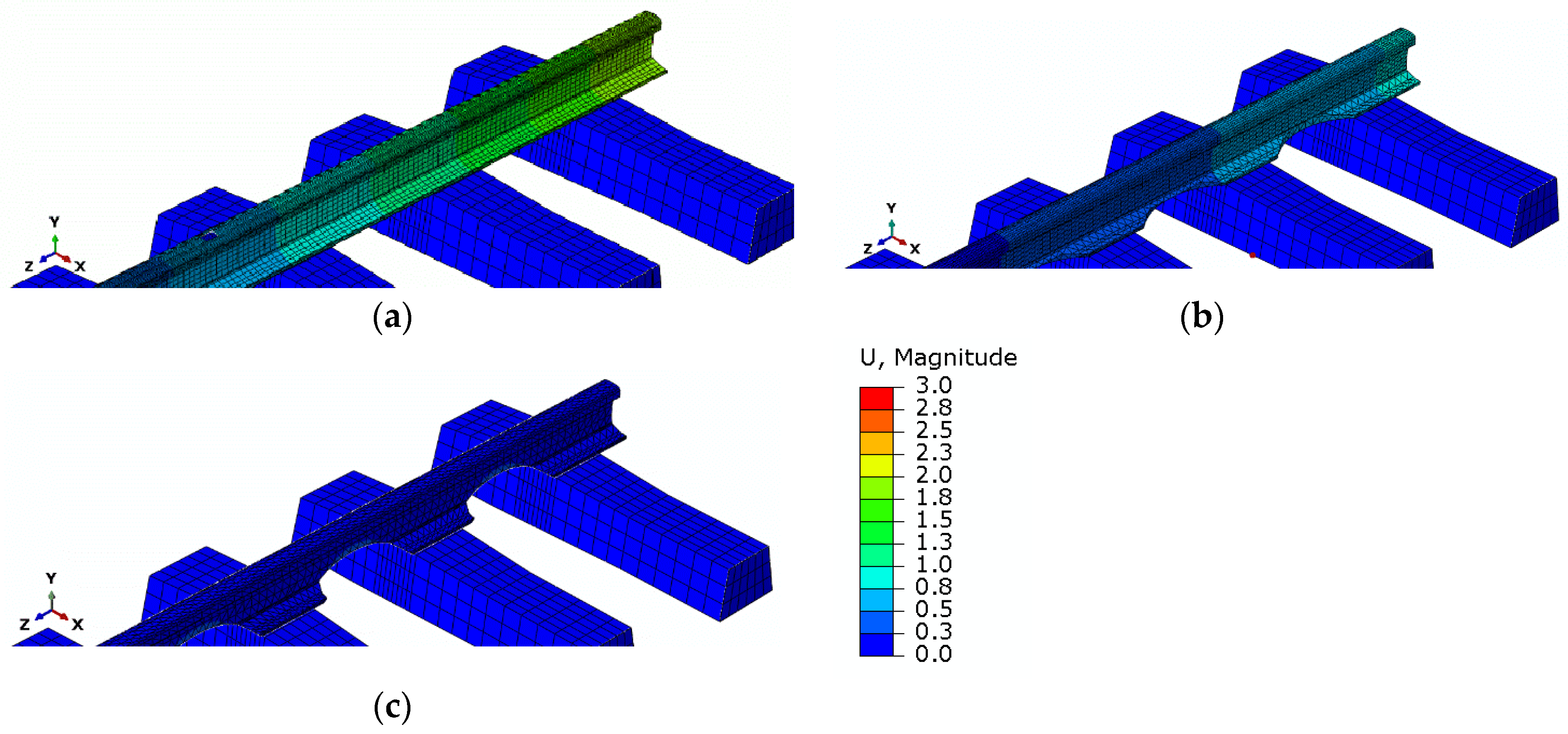
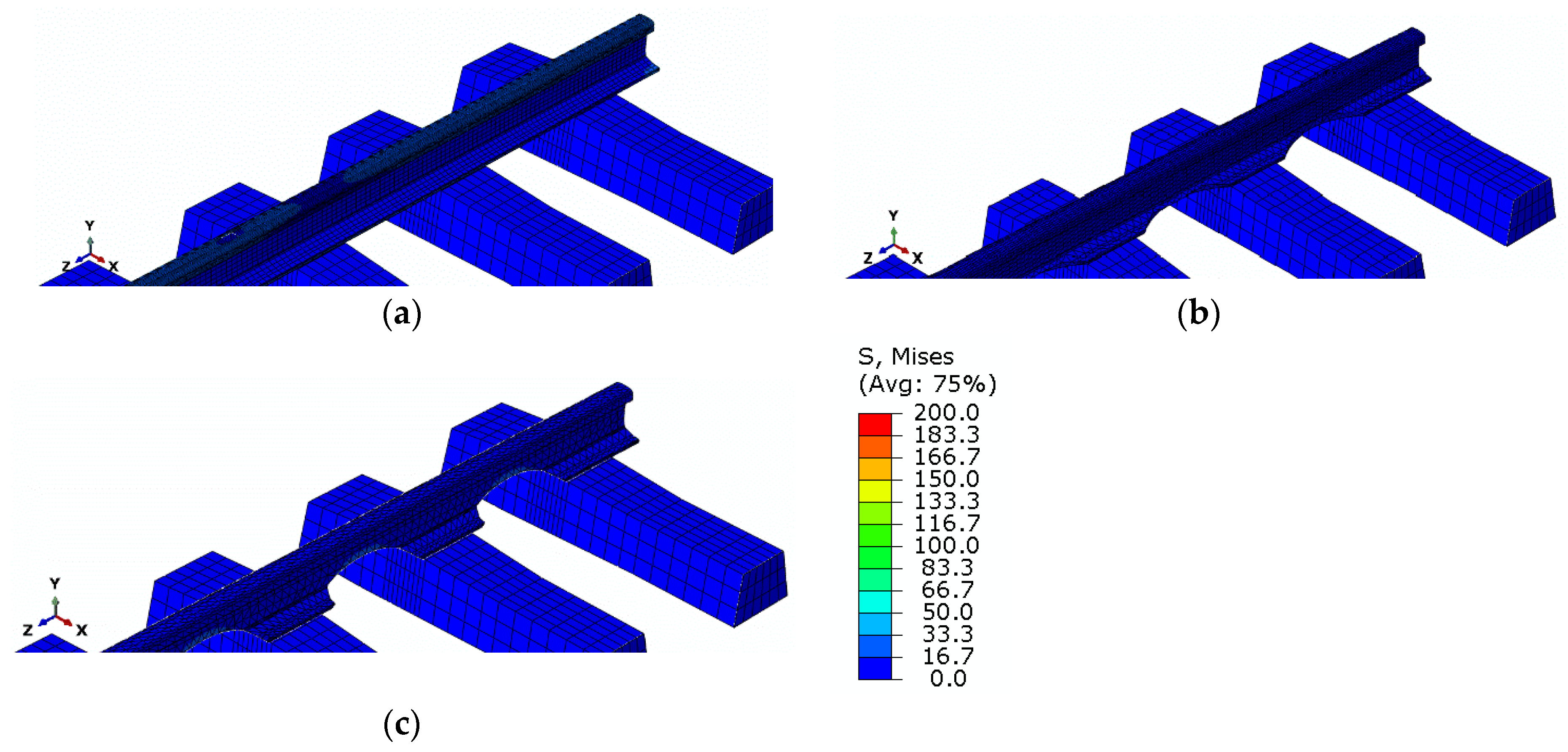
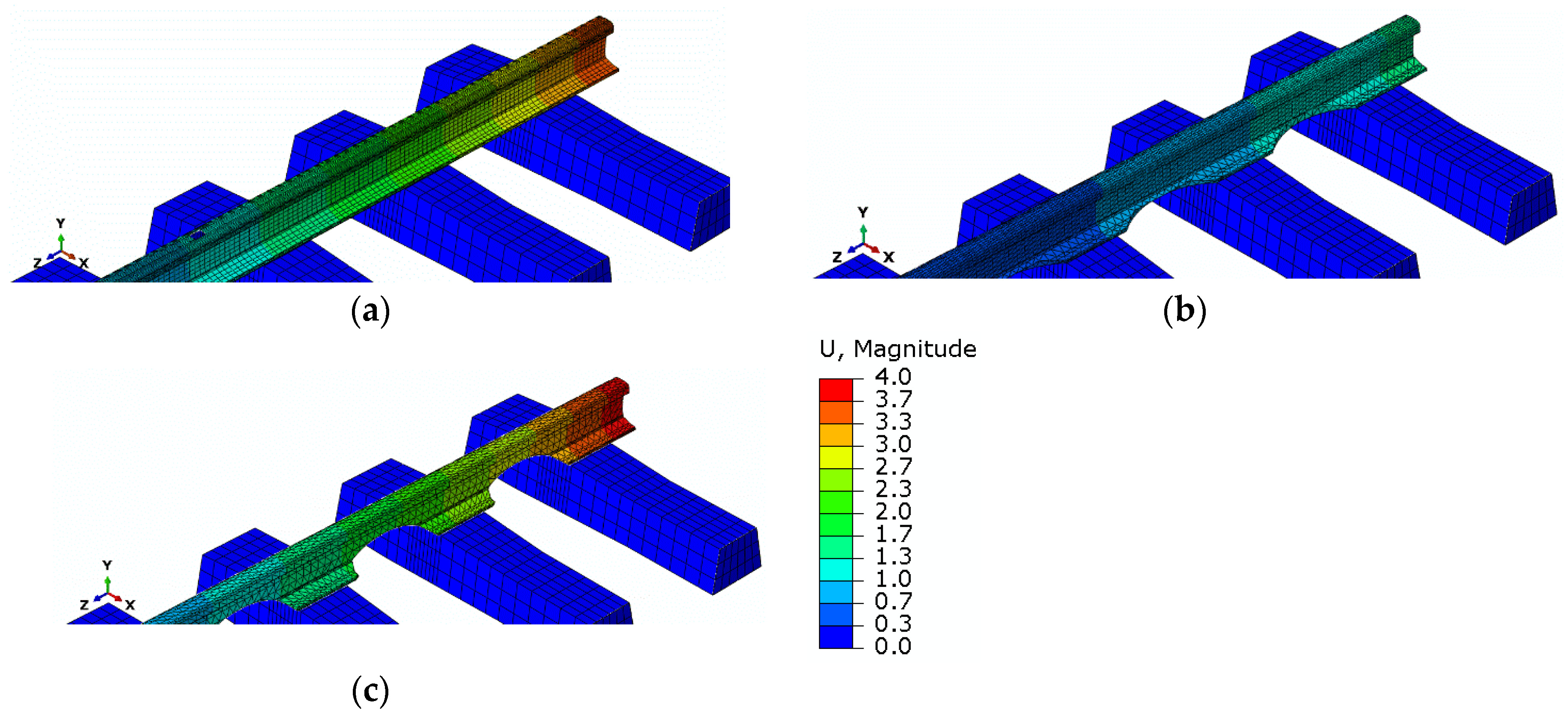
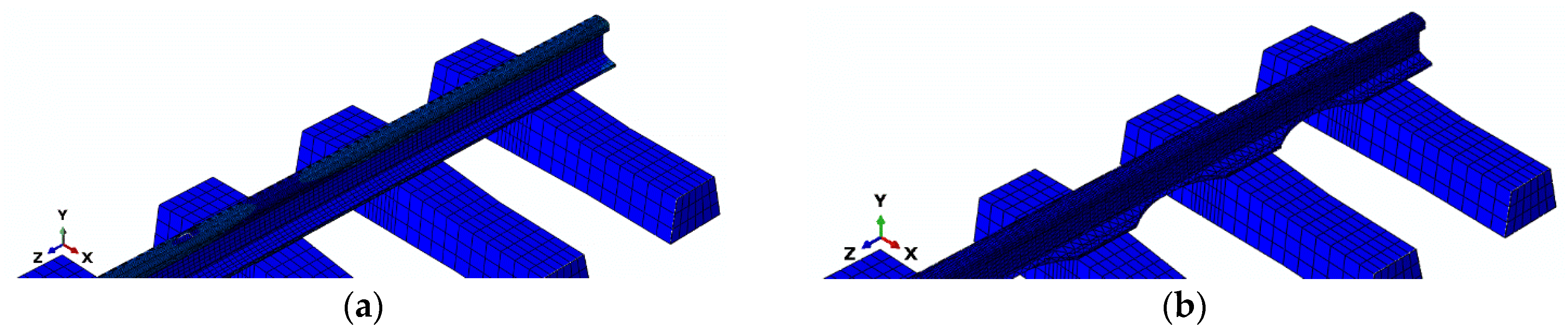
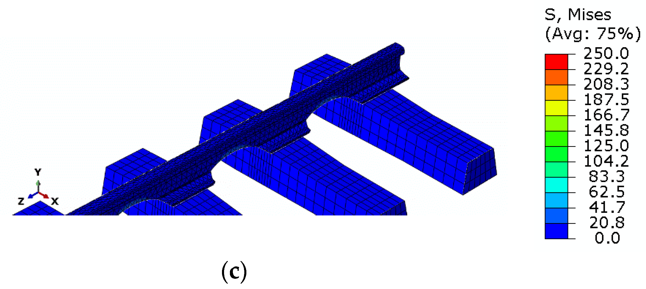
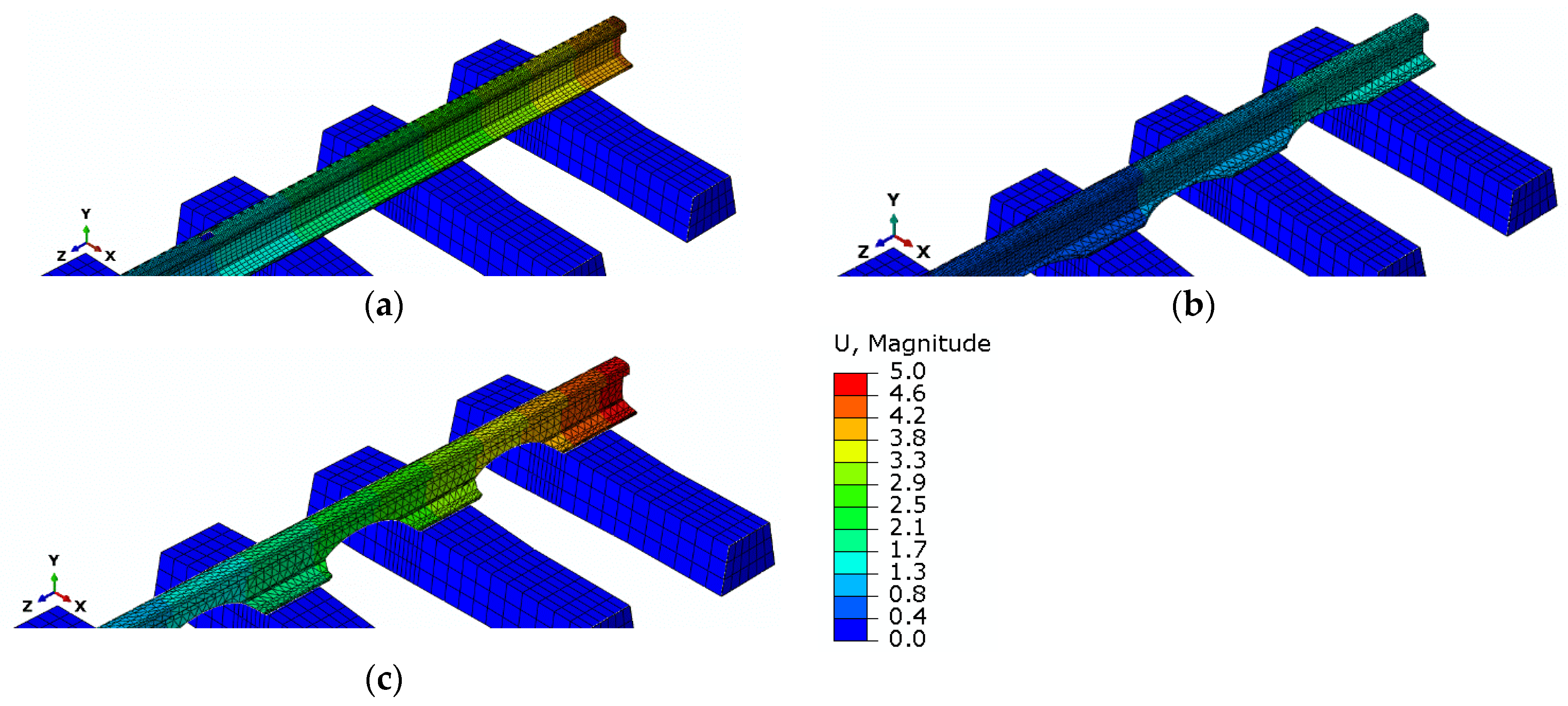
5. Results of Simulation Studies
6. Evaluation of Simulation Studies
7. Conclusions
- Simulation studies for other cases such as a different rail profile (49E1);
- Simulation studies of a track variant located in a circular curve with different radii;
- Simulation studies of dynamic loads from a railroad vehicle.
- In the long term, the following is planned.
- Establishing cooperation with a steel mill producing steel components (including rails);
- Obtaining funding to conduct experimental research on real objects.
Author Contributions
Funding
Institutional Review Board Statement
Informed Consent Statement
Data Availability Statement
Conflicts of Interest
References
- Kish, A.; Samavedam, G.; Al-Nazer, L. Track Buckling Prevention: Theory, Safety Concepts, and Applications; RRD Report Number DOT/FRA/ORD-13/16; U.S. Department of Transportation, Federal Railroad Administration: Washington, DC, USA, 2013. [Google Scholar]
- Błaszkiewicz-Juszczęć, D.; Czyczuła, W.; Kudła, D. Identification of Track Stability Model Parameters Based on Numerical Experiments. Appl. Sci. 2022, 12, 570. [Google Scholar] [CrossRef]
- Binti Sa’adin, S.L.; Kaewunruen, S.; Jaroszweski, D. Risks of Climate Change with Respect to the Singapore-Malaysia High Speed Rail System. Climate 2016, 4, 65. [Google Scholar] [CrossRef]
- Ngamkhanong, C.; Wey, C.M.; Kaewunruen, S. Buckling Analysis of Interspersed Railway Tracks. Appl. Sci. 2020, 10, 3091. [Google Scholar] [CrossRef]
- Ratkiewicz, A.; Kukulski, J. Horizontally-Radially Cut Rail and Its Application. Patent Application No. 58389; Document ID 885878, 12 December 2023. [Google Scholar]
- Ratkiewicz, A.; Kukulski, J. Vertically-Radially Cut Rail and Its Application. Patent Application No. 58390; Document ID 885889, 12 December 2023. [Google Scholar]
- Lim, N.H.; Park, N.H.; Kang, Y.J. Stability of continuous welded rail track. Comput. Struct. 2003, 81, 2219–2236. [Google Scholar] [CrossRef]
- Pucillo, G. Thermal buckling and post-buckling behaviour of continuous welded rail track. Veh. Syst. Dyn. 2016, 54, 1785–1807. [Google Scholar] [CrossRef]
- Safizadeh, A.; Jabbar, A.Z.; Nobakht, S. Laboratory investigation on contribution of fastening system and sleeper in longitudinal resistance of ballasted railway tracks. Road Mater. Pavement Des. 2023, 24, 1712–1727. [Google Scholar] [CrossRef]
- Ole, Z.K. Track Stability and Buckling-Rail Stress Management. Bachelor’s Dissertation, Faculty of Engineering and Surveying, University of Southern Queensland, Toowoomba, Australia, 2008. [Google Scholar]
- Khabardin, V.N.; Khabardin, A.V. Light-Weight Design Railway Rail. Patent EA029813B1, 2014. [Google Scholar]
- Żak, S.; Woźniak, D. Controlling the State of Residual Stresses in Railway Rails by Modifying Pass Design of Straightening Rollers. Arch. Metall. Mater. 2023, 68, 57–70. [Google Scholar] [CrossRef]
- Ngamkhanong, C.; Kaewunruen, S. Prediction of Thermal-Induced Buckling Failures of Ballasted Railway Tracks Using Artificial Neural Network (ANN). Int. J. Struct. Stab. Dyn. 2022, 22, 2250049. [Google Scholar] [CrossRef]
- Hong, S.; Park, C.; Cho, S. A Rail-Temperature-Prediction Model Based on Machine Learning: Warning of Train-Speed Restrictions Using Weather Forecasting. Sensors 2021, 21, 4606. [Google Scholar] [CrossRef] [PubMed]
- Austill, R. Process for Determining and Controlling Railroad Rail’s Neutral Temperature to Prevent Track Buckling and Rail Fractures. Patent US5161891A, 10 November 1992. [Google Scholar]
- Harrison, H. Stress Monitoring System for Railways. Patent US2007044566A1, 11 January 2011. [Google Scholar]
- Wegner, A. Prevention of Track Buckling and Rail Fracture by Non-destructive Testing of the Neutral Temperature in CWR-Rails. In Proceedings of the IHHA Spezialist Technical Session (STS), Kiruna, Sweden, 11 June 2007. [Google Scholar]
- Liang, K. Method for Detecting and Tracking Buckling Branch Path of Structure with High Efficiency and High Precision. Patent CN105373654A, 24 May 2019. [Google Scholar]
- Struwig, F.A.; Kunneke, C. Device, System and Method for Monitoring Conditions on A Railway Track. Patent US2022111878A1, 2022. [Google Scholar]
- Knopf, K.; Rizos, D.C.; Qian, Y.; Sutton, M. A non-contacting system for rail neutral temperature and stress measurements: Concept development. Struct. Health Monit. 2021, 20, 84–100. [Google Scholar] [CrossRef]
- Smith, F. Apparatus and Method for Monitoring Railroad Track for Buckling Risk. Patent US2023417624A1, 2023. [Google Scholar]
- Montalbán Domingo, L.; Real Herraiz, J.I.; Zamorano, C.; Real Herraiz, T. Design of a new high lateral resistance sleeper and performance comparison with conventional sleepers in a curved railway track by means of finite element models. Lat. Am. J. Solids Struct. 2014, 11, 1238–1250. [Google Scholar] [CrossRef]
- Chalabii, J.; Movahedi Rad, M.; Hadizadeh Raisi, E.; Esfandiari Mehni, R. Effect of Sleeper-Ballast Particle Contact on Lateral Resistance of Concrete Sleepers in Ballasted Railway Tracks. Materials 2022, 15, 7508. [Google Scholar] [CrossRef] [PubMed]
- Jing, G.; Ji, Y.; Aela, P. Experimental and numerical analysis of anchor-reinforced sleepers’ lateral resistance on ballasted track. Constr. Build. Mater. 2020, 264, 120197. [Google Scholar] [CrossRef]
- Zakeri, J.A.; Mohammadzadeh, S.; Barati, M. New Definition of Neutral Temperature in Continuous Welded Railway Track Curves. Period. Polytech. Civ. Eng. 2018, 62, 143–147. [Google Scholar] [CrossRef]
- Mandal, N.; Lees, M. Effectiveness of measuring stress-free temperature in continuously welded rails by Rail Creep Method and Rail Stress Modules. Eng. Fail. Anal. 2019, 104, 189–202. [Google Scholar] [CrossRef]
- Wong, R. Geothermal Rail Cooling and Heating System. Patent US2014033755A1, 26 August 2014. [Google Scholar]
- Giunta, M. Trends and Challenges in Railway Sustainability: The State of the Art regarding Measures, Strategies, and Assessment Tools. Sustainability 2023, 15, 16632. [Google Scholar] [CrossRef]
- Wang, H.; Xing, C.; Deng, X. Effect of Random Lateral Ballast Resistance on Force-Deformation Characteristics of CWR with a Small-Radius Curve. Materials 2023, 16, 2876. [Google Scholar] [CrossRef] [PubMed]
- Momotani, Y.; Nakamura, T. Rail Track Buckling Prevention Device and Ballast Rail Track Including the Rail Track Buckling Prevention Device. Patent JP2016191264A, 10 November 2016. [Google Scholar]
- Wang, P. Stress Came Loose Roller on Sleepers for Seamless Line. Patent CN2647907Y, 13 October 2004. [Google Scholar]
- Fei, H. Steel Track Buckling Piece System and Track Distance Blocking Plate. Patent CN103437253A, 17 June 2015. [Google Scholar]
- Miri, A.; Zakeri, J.; Thambiratnam, D.P.; Chan, T.H.T. Mitigation of track buckling in transition zones of steel bridges by geotextile reinforcement of the ballast layer. Geotext. Geomembr. 2022, 50, 282–292. [Google Scholar] [CrossRef]
- Lee, H.D.; Choi, S.; Moon, J. Lateral Resistance Requirement of Girder-Sleeper Fastener for CWR Track on an Open-Deck Steel Plate Girder Bridge. Appl. Sci. 2021, 11, 6681. [Google Scholar] [CrossRef]
- Mirković, N.; Nefovska-Danilović, M.; Ahac, M.; Lakušić, S.; Mirković, U.; Zafirovski, Z. Parametric Study of Additional Temperature Stresses in Continuously Welded Rails on Steel Truss Railway Bridges. Buildings 2023, 13, 2296. [Google Scholar] [CrossRef]
- Hosokawa, S.; Yamazaki, Y. Buckling Prevention Device of Track. Patent JP2012021292A, 6 April 2016. [Google Scholar]
- Xiao, X.; Zhang, Q.; Zheng, J.; Li, Z. Analytical model for the nonlinear buckling responses of the confined polyhedral FGP-GPLs lining subjected to crown point loading. Eng. Struct. 2023, 282, 115780. [Google Scholar] [CrossRef]
- Li, Z.; Zhang, Q.; Shen, H.; Xiao, X.; Kuai, H.; Zheng, J. Buckling performance of the encased functionally graded porous composite liner with polyhedral shapes reinforced by graphene platelets under external pressure. Thin-Walled Struct. 2023, 183, 110370. [Google Scholar] [CrossRef]
- Xiao, X.; Bu, G.; Ou, Z.; Li, Z. Nonlinear in-plane instability of the confined FGP arches with nanocomposites reinforcement under radially-directed uniform pressure. Eng. Struct. 2022, 252, 113670. [Google Scholar] [CrossRef]


| Parameter | Value | Unit |
|---|---|---|
| Modulus of elasticity of the rail 60E1 | 210,000 | MPa |
| Modulus of elasticity of the sleeper | 30,200 | MPa |
| Rail density 60E1 | 7850 | kg/m3 |
| Sleeper density | 2400 | kg/m3 |
| Poisson’s ratio of a rail 60E1 Poisson’s ratio of the sleeper | 0.30 0.20 | - - |
| Damping of the railway sleeper | 250 | kNs/m |
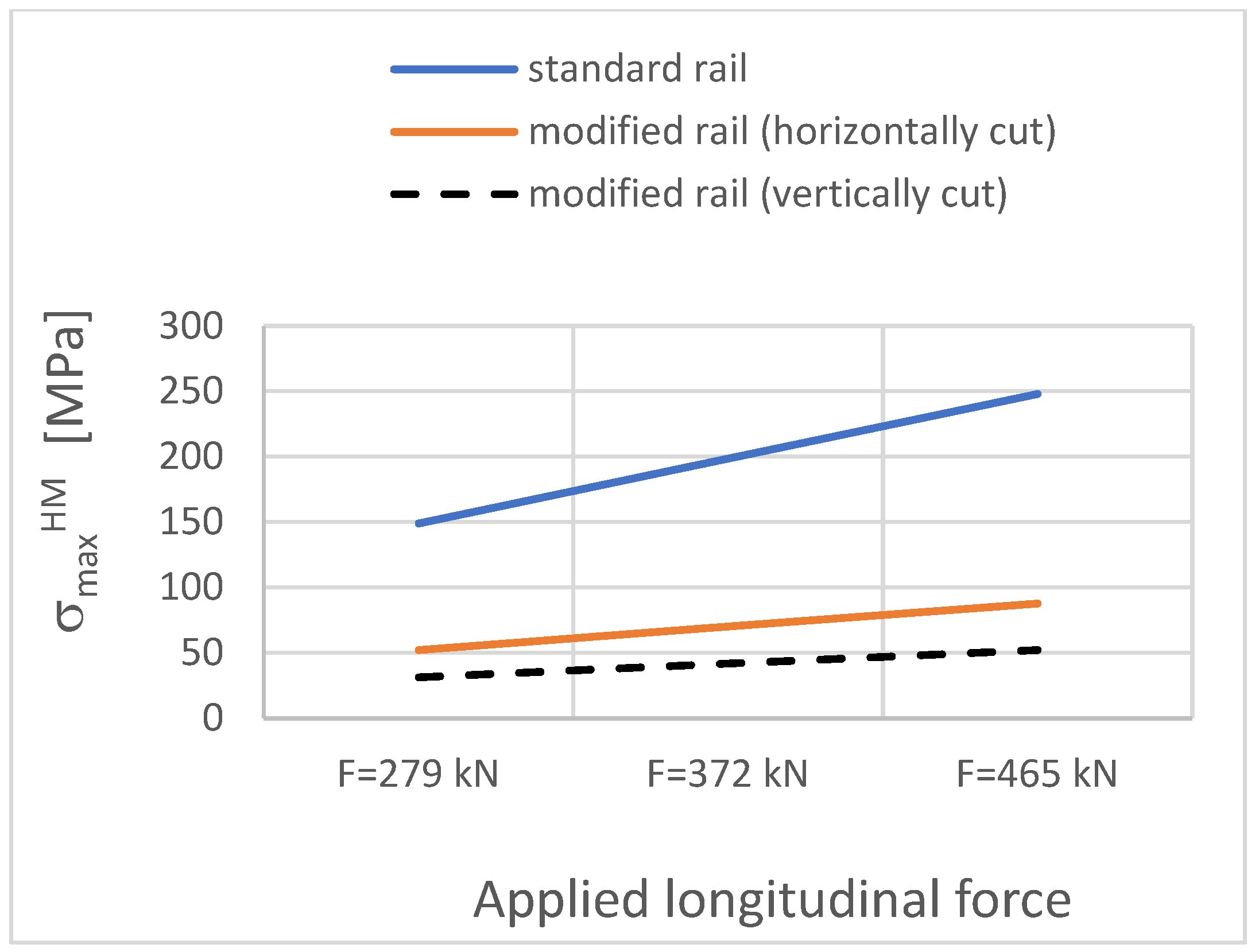
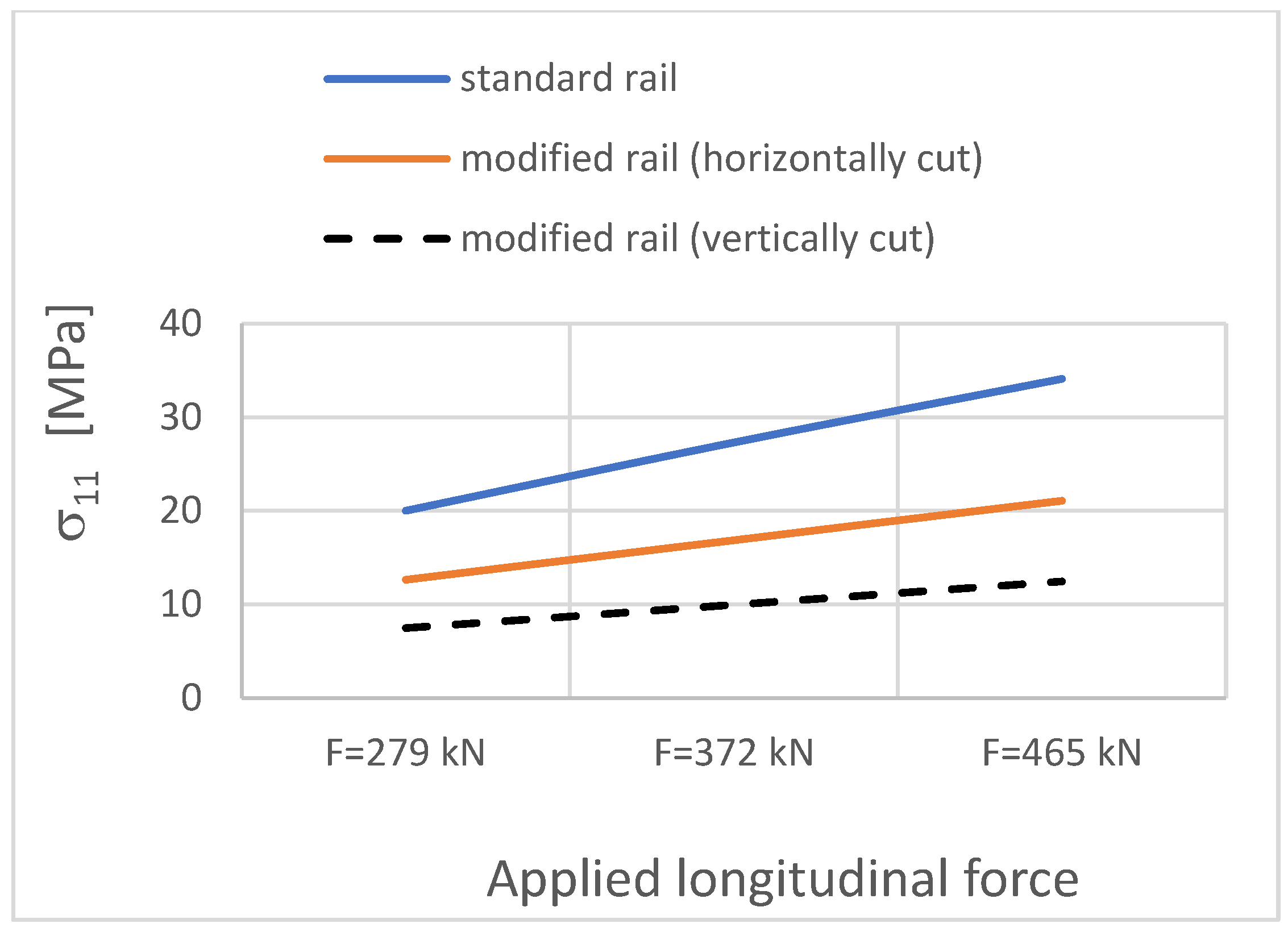
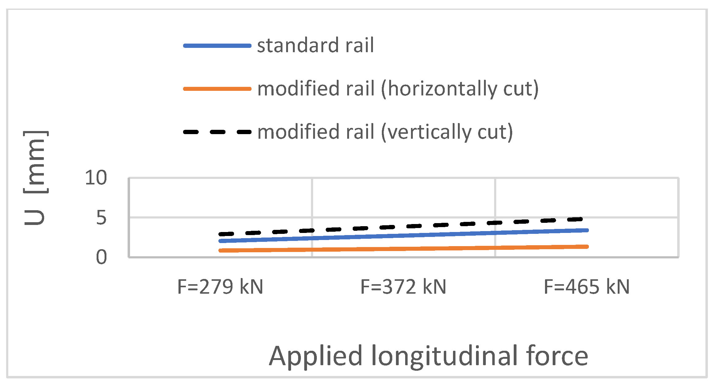
| Applied Longitudinal Force FT [kN] | Track Model—Straight Section, Standard Rail | Track Model—Straight Section, Modified Rail (Horizontally Cut) | Track Model—Straight Section, Modified Rail (Vertically Cut) | ||||||
|---|---|---|---|---|---|---|---|---|---|
| σmaxHM [MPa] | σ11 [MPa] | U [mm] | σmaxHM [MPa] | σ11 [MPa] | U [mm] | σmaxHM [MPa] | σ11 [MPa] | U [mm] | |
| 279 kN (temperature increase by 15 °C) | 148.9 | 20.01 | 2.05 | 52.1 | 12.65 | 0.86 | 31.3 | 7.47 | 2.90 |
| 372 kN (temperature increase by 20 °C) | 198.6 | 27.31 | 2.74 | 70.1 | 16.87 | 1.07 | 41.8 | 9.96 | 3.87 |
| 465 kN (temperature increase by 25 °C) | 248.0 | 34.11 | 3.42 | 87.7 | 21.08 | 1.34 | 52.2 | 12.46 | 4.84 |
Disclaimer/Publisher’s Note: The statements, opinions and data contained in all publications are solely those of the individual author(s) and contributor(s) and not of MDPI and/or the editor(s). MDPI and/or the editor(s) disclaim responsibility for any injury to people or property resulting from any ideas, methods, instructions or products referred to in the content. |
© 2024 by the authors. Licensee MDPI, Basel, Switzerland. This article is an open access article distributed under the terms and conditions of the Creative Commons Attribution (CC BY) license (https://creativecommons.org/licenses/by/4.0/).
Share and Cite
Kukulski, J.; Ratkiewicz, A. Concept of Thermal Shrinkage-Resistant Railroad Rail for Use in Continuous Welded Rail Track. Appl. Sci. 2024, 14, 6172. https://doi.org/10.3390/app14146172
Kukulski J, Ratkiewicz A. Concept of Thermal Shrinkage-Resistant Railroad Rail for Use in Continuous Welded Rail Track. Applied Sciences. 2024; 14(14):6172. https://doi.org/10.3390/app14146172
Chicago/Turabian StyleKukulski, Jacek, and Andrzej Ratkiewicz. 2024. "Concept of Thermal Shrinkage-Resistant Railroad Rail for Use in Continuous Welded Rail Track" Applied Sciences 14, no. 14: 6172. https://doi.org/10.3390/app14146172
APA StyleKukulski, J., & Ratkiewicz, A. (2024). Concept of Thermal Shrinkage-Resistant Railroad Rail for Use in Continuous Welded Rail Track. Applied Sciences, 14(14), 6172. https://doi.org/10.3390/app14146172