Article

Study on the Stability and Reasonable Width of Coal Pillars in “Three Soft” Coal Seams Based on a Physical Similarity Simulation Experiment

1
School of Energy, Xi’an University of Science and Technology, Xi’an 710054, China
2
College of Safety Science and Engineering, Xi’an University of Science and Technology, Xi’an 710054, China
3
Information Institute, Ministry of Emergency Management of the PRC, Beijing 100029, China
*
Author to whom correspondence should be addressed.
Appl. Sci. 2024, 14(14), 6127; https://doi.org/10.3390/app14146127
Submission received: 2 July 2024 / Revised: 10 July 2024 / Accepted: 11 July 2024 / Published: 14 July 2024

Abstract

As the depth of coal seams increases and the demand for coal grows, the deformation and failure of roadways and coal pillars also intensify. To address the instability of roadways, it is crucial to study the appropriate dimensions for coal pillars. This paper focuses on the 1513 working face of the No. 5 coal seam at Anyang Coal Mine to address the issue of insufficient basis for determining coal pillar width. Through field observations and physical similarity simulations, this study examines the overlying strata failure patterns above coal pillars post-mining and the bearing structure formed by key layers. The relationship between these factors is analyzed using theoretical analysis and physical similarity simulations. A mechanical model of the coal pillar and the “hinged-hinged” overlying strata failure structure is established, analyzing the fracture characteristics of the overlying strata and the bearing structure of the coal pillar to determine the optimal coal pillar width under these conditions. The results indicate that when the coal pillar width is optimized from 25 m to 14 m, the overlying bearing layer is disrupted by the mining activities at the working face, with the lower key layer forming a “hinged” structure upon fracture. As mining progresses, the height of the overlying strata fractures gradually increases, causing the upper key layer to also fracture and form a “hinged-hinged” structure between the high and low bearing layers. According to the “three zones” development law, the height of overlying strata failure does not continue to increase indefinitely, and the coal pillar is affected by the “hinged-hinged” structure of the bearing strata. A mechanical model of the coal pillar bearing structure is established based on the fracture combination structure of the bearing strata. By calculating the load on the “hinged-hinged” structure of the overlying strata, the appropriate coal pillar width is determined to be 15 m. Theoretical calculations, physical similarity simulation experiments, and field applications show that without changing the support conditions, the deformation of the roadway is greater when the coal pillar is narrowed, compared to its original width. The maximum deformation, located 60 m ahead of the working face, increased by 41–42%, while deformation in other areas was relatively minor. This validates the reasonableness of the determined coal pillar width.

1. Introduction

With the gradual exploitation of shallow coal resources in China, the development and utilization of deep coal resources has become an important way to solve energy problems. However, with the increase in mining height and mining intensity, the deformation and failure of roadway-surrounding rock becomes more and more obvious [1,2]. In order to improve the stability of the back-mining roadway and reduce the damage range and deformation degree of the roadway-surrounding rock, mines often use the method of leaving coal pillars to improve the stress situation of the working face and reduce the concentrated stress of the surrounding rock of the back-mining roadway, so as to ensure the safety of the lower section of the back-mining roadway [3]. However, the retention of coal pillars often causes a waste of coal resources. If the size of the coal pillars is large, it will further aggravate the waste of resources. If the size of the coal pillars is small, it is affected by geological conditions and the high stress of the working face, which can easily cause the instability of coal pillars [4,5,6]. The phenomenon is more prominent under the conditions of thick unconsolidated layers and three soft coal seams. Therefore, the reasonable size selection and stability control of coal pillars are of great significance to mine production.
At present, a large number of studies have been carried out on the stability control of coal pillars in three soft coal seams. Wang International et al. [7] used UDEC to simulate three soft coal seams, analyzed the different distribution ranges of the overtopping stress generated in front of the coal wall when advancing to different distances, and obtained the distribution of the three zones of the overlying rock strata in this working face. Li et al. [8] studied the stress distribution law of the surrounding rock along the hollow stay and found that the influence range of the over-support pressure reaches about 50 m ahead. The peak value of lateral stress value is about 10 m from the coal wall, and the influence range of stress concentration is about 30~40 m. The stress concentration is about 10 m from the coal wall. In addition, it was indicated that 70 m behind the mining hollow area is a better location for roadway maintenance. Xu et al. [9] investigated the support stress distribution characteristics of three soft coal seams and pointed out that the mining overrun influence distance of the three soft coal seam working face is larger than that of the general working face. Wang et al. [10,11] determined the failure of the roadway perimeter rock support structure under the influence of high mining pressure in the roadway of three soft coal seams through the experimental study of rock mechanics of three soft coal seams. Based on a generalized neural network algorithm, Lai et al. [12,13,14] constructed a neural network prediction model for the width of coal pillar retention in a section of near-horizontal working face, which provides a reference basis for realizing the accurate mining of near-horizontal comprehensive mining working faces. Zhang et al. [15,16,17] analyzed the damage characteristics of soft rock roadways, established the mechanical structure model of soft rock roadways, and analyzed the destabilization characteristics under soft rock roadways. Xie [18] established a mathematical analysis model of the roof-coal pillar group system and elucidated the destabilization process of the roof–coal pillar group system under rheological conditions. Zhang et al. [19] studied the distribution of stress, displacement, and plastic zones of coal pillars under different widths and determined the reasonable retention width of coal pillars in the section. Cui et al. [20] established a mechanical model of sliding coal wall spalling for the problem of coal pillar side deflection in three soft coal seam roadways. Based on the stress evolution law of physical similarity Moyer experiment, the main influencing factors of coal wall spalling were put forward, and finally, the effective control technology of rib spalling disaster in three soft coal seams was put forward. Based on the limit equilibrium theory of the D-P criterion and indoor rock mechanics test, Li, et al. [21] analyzed the failure and deformation of coal walls on the side of coal pillars in soft coal seam roadways in deep mining. The results show that when the water content of the coal seam reaches 3.3%, the uniaxial compressive strength of soft coal reaches the maximum value, which can withstand the influence of coal pillar reduction. Jiang et al. [22] established an internal and external stress field model for the design of large-scale instability and the failure of coal pillars and support systems in high-stress soft coal seams in deep mines. Through numerical simulation, theoretical analysis, and field engineering practice, the key areas of GSED surrounding rock prevention and control were clarified. Based on the minimum coal pillar size obtained through theoretical calculations, a reasonable surrounding rock reinforcement technology was proposed.
The existing research on the width of section coal pillars has provided valuable references for this paper. However, the impact of the fractured structure of the overlying bearing strata on the stress of coal pillars, particularly in “three soft” coal seams when reducing the size of the coal pillar, requires further investigation. This study focuses on the section coal pillar of the 1513 working face of the five coal seam in Anyang Coal Mine. Utilizing the limit equilibrium theory [23] and elastic mechanics theory [24], the failure mechanism of the coal pillar influenced by mining activities is analyzed. Both physical similarity and numerical simulations are employed to validate the findings, examining the stress distribution characteristics under varying coal pillar widths and the failure patterns of the coal pillar [25,26]. The results aim to provide a reference for safe mining operations under similar conditions.

2. Engineering Background

Anyang Coal Mine, situated in Weinan City, Shaanxi Province, features the 1513 working face located in the eastern part of the No. 5 coal seam within the plain area east of Jinshuigou. The surface is extensively covered by loess, with numerous farmland orchards and no river water. The working face has an average burial depth of 370 m, a coal seam thickness of 4.5 m, and a dip angle ranging from 2° to 17°, with an average of 8°. The return airway is situated on the south side of the working face, the 1512 goaf on the west, and the 1514 working face on the north. The strike length of the working face is 1500 m, and the dip length is 180 m. The mining layout of the 1513 working face is illustrated in Figure 1. The working face employs a single-strike long-wall mining method, advancing 3.2 m daily, utilizing a comprehensive mechanized mining process and a complete caving method for roof management. Due to the potential for spontaneous combustion in the goaf, the working face is sealed upon completion of mining. The layout of the working face is shown in Figure 1.
The lithology of the roof and floor of the coal seam at the working face is illustrated in Figure 2. The roof comprises 2 m of siltstone, characterized by significant horizontal bedding and minor crossbedding, with an additional 2 m thin coal seam above the siltstone. The floor consists of 1 m of carbonaceous mudstone, which is prone to expansion in water and has a softening coefficient of 0.59. The underlying base is quartz sandstone, with a uniaxial compressive strength of 34.1 MPa under dry conditions and 18.8 MPa when saturated. Considering that both the roof and floor of the coal seam consist of soft rock, it is crucial to study the coal pillar width to minimize its size while avoiding damage to the roadway.

3. Fracture Structure and Stability Analysis of Coal Pillar Overburden Rock

3.1. Physical Simulation Model Design

To simulate the appropriate size and failure characteristics of the section coal pillar between the 1512 and 1513 working faces of the No. 5 coal seam in Anyang Coal Mine, a three-dimensional model frame with dimensions of 2000 mm (length) × 970 mm (width) × 200 mm (height) was used for a physical simulation experiment. The overlying strata were not constructed; instead, iron bricks were laid to replicate the equivalent load. River sand was chosen as the aggregate for the experiment, and large white powder and gypsum glue, mixed in specific proportions, served as the bonding materials. According to the similarity theory of simulation tests, the geometric similarity constant was set to 10, the bulk density similarity constant was set to 1.6, and the strength similarity constant was set to 16. The parameters and material ratios for a similar material model are detailed in Table 1. Stress sensors were installed at the bottom of the model, and three ultrasonic detectors were pre-positioned above the model. Displacement measuring points for the rock strata and surface were established, with observations of displacement, stress, and overburden fracture photography conducted during the mining process.

3.2. Characterization of the Broken Structure of the Coal Pillar Overburden

This study primarily focuses on the geological conditions beneath the soft coal seam. The movement law of the overburden rock during the process of rock breakage and the stress values on the coal pillars are analyzed using indoor tests [27,28].
As shown in Figure 3,The figure illustrates the failure characteristics of the overlying strata at varying mining distances. Due to the presence of a thin coal seam, only 1 m thick, above the roof, the roof’s load-bearing capacity is compromised. When the working face advances to 34 m, the initial pressure is observed at the basic top. As the working face continues toward the coal pillar side, 11 cyclic breaks occur, averaging 17.3 m per step. The upper key layer experiences periodic breakages seven times, averaging 23.7 m per step. Consequently, the overburdened rock fractures and collapses, destroying its load-bearing structure and forming an “articulated” support configuration for the overlying rock. Based on calculations of the development height of the water-conducting fissure zone [29], once the overlying rock damage extends to 75 m, it is no longer influenced by the key layer, resulting in the formation of an “articulated-articulated” structure, with the breakage of two key layers. Throughout this process, significant deformation and deflection were observed on the coal pillar side of the 1513 return air lane at the site.
An analysis of the structure and morphology of the overlying strata in a similar simulation experiment reveals that the direct roof, composed of interbedded coal and siltstone, collapses and settles neatly into the goaf during the mining of the working face. As the working face advances continuously and reaches full extraction, the rock layers periodically fracture, resulting in a cyclic “hinged” structure in the lower bearing rock layer and similarly in the upper bearing rock layer. These two bearing rock layers combine to form a “hinged-hinged” structure above the coal pillar, exerting simultaneous stress on it, leading to stress concentration within the coal pillar.
The data obtained from the stress meter placed on the floor of the physical similarity model indicate that the vertical stress peak occurs at the central axis of the coal pillar at a depth of 14 m, as shown in Figure 4. The coal pillar, with a width of 25 m, remains stable overall, exhibiting an M-shaped stress curve. The highest stress, reaching 12.9 MPa, is observed on the goaf side. As the coal pillar width decreases, vertical stress increases rapidly, causing the stress curve to transition from an M-shape to a single peak. The vertical stress increases steadily as the width decreases from 25 m to 14 m. The transition from a double-peak stress distribution at 25 m to a single peak at 14 m results in a 29.1% increase in stress, reaching 18.4 MPa. Due to the weak nature of the five coal seams, a narrower coal pillar width corresponds to higher vertical stress.
Hence, to ensure the operational integrity of the 1513 working face’s return airway and maximize coal recovery, a thorough analysis of the coal pillar width is essential.

4. Analysis of Coal Pillar Bearing Structure after Coal Seam Mining

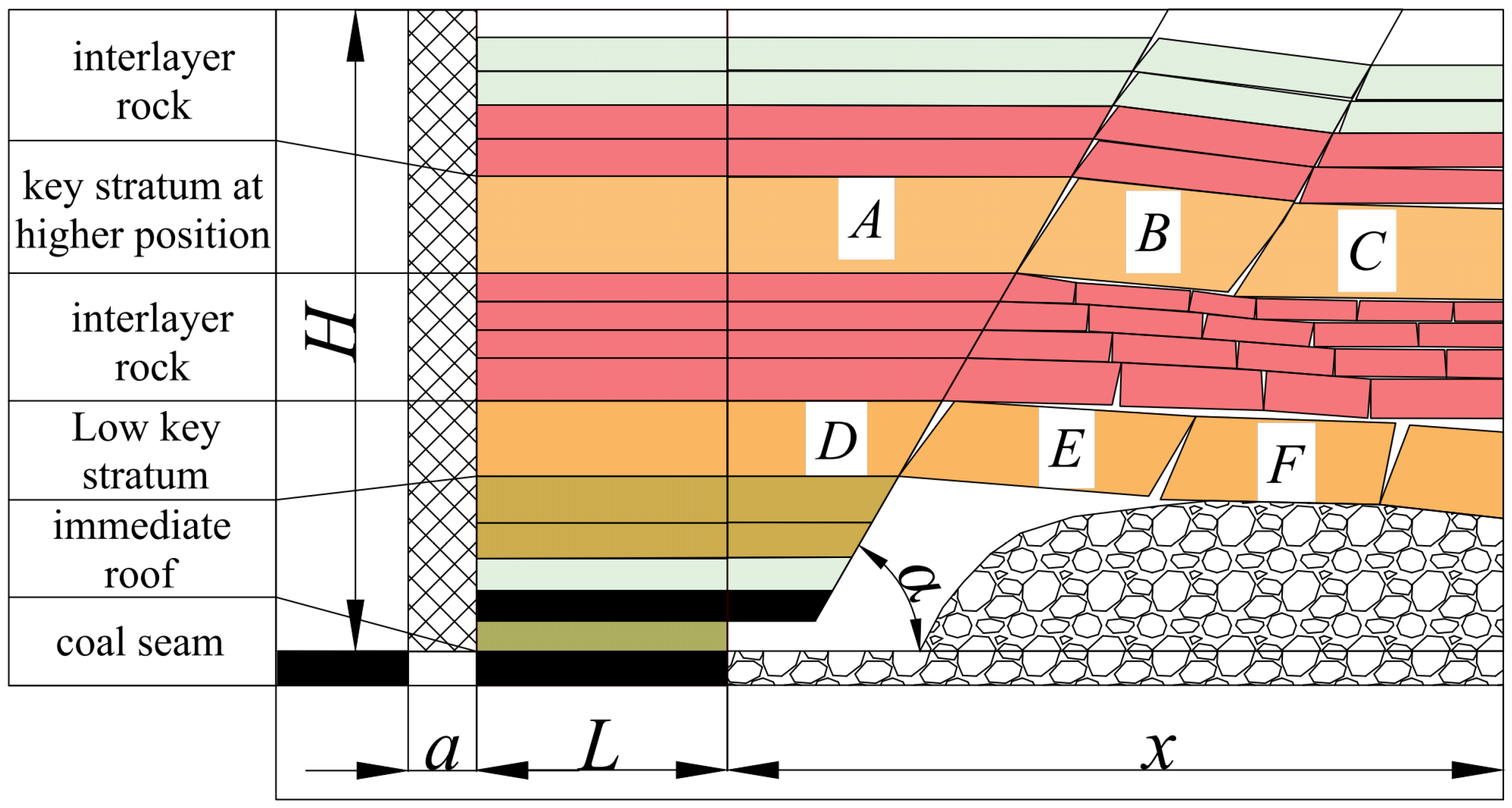
4.1. Mechanical Analysis of High Bearing Structure of Coal Pillar

After the coal seam is mined, forming a goaf with a length of x, the immediate roof exhibits an irregular caving shape, creating a cantilever beam structure near the coal pillar side. The fracture line forms a specific angle with the goaf. Due to the mining height, the basic roof fractures within the goaf. As the gangue in the goaf is compacted, a hinged structure forms near the basic roof on the coal pillar side. The stress generated by the movement of the key block gradually transfers to the interior of the coal pillar and the deeper parts of the goaf. At this point, coal pillar L is subjected to the load H of the overlying strata and the forces from the bearing strata breaking onto the coal pillar. The 1513 return airway is also affected by the coal pillar. This establishes the mechanical model of the coal pillar-bearing structure, as illustrated in Figure 5.
Upon completion of the 1512 working face, the mining disturbance causes the basic roof of the goaf to fracture, forming a “masonry beam” structure. The fracture line and the goaf create a specific angle. As key block B rotates and subsides, the key blocks compress against each other, generating horizontal thrust. This interaction creates shear and friction between the blocks, which supports the overlying strata, as illustrated in Figure 6.
In the diagram, P1 is the load applied by the overlying strata to the key block B, kN/m; T is horizontal thrust, kN; QA is the support force of coal pillar to key block B, kN; QB is the support force of the gangue in the goaf to the key block C, kN; L1 is the length of key block B, m; θ is the rotation angle of the key block B, °; and h1 is the thickness of the block rock beam, m.
Once mining of the working face is completed, the immediate roof collapses, and the rock stratum undergoes rotation and fracturing, creating a fracture zone. Due to the positioning of the key stratum, the bending subsidence zone experiences minimal damage and functions in supporting the overlying rock stratum.
Due to mining disturbance, the overlying strata develop fracture zones and bending subsidence zones, which are distinctly separated. Concurrently, rock blocks fracture, leading to an interruption in force transmission. Consequently, the load exerted on the overlying strata P1 is as follows:
P 1 = L 1 γ 1 h 1 K G
In the formula, γ1 represents the average bulk density (kN/m3) of the upper load rock layer of the key block B, h1 denotes the thickness (m) of the upper load rock layer of the key block, and KG stands for the load transfer coefficient.
The internal force key block B comprises PZB, as follows:
P Z B = L 1 γ 2 h 1
In the formula, γ2 is the average bulk density of the key block B, kN/m3.
The geometric relationship of rock mass after rotation is shown in Figure 6. According to the geometric characteristics of rock mass rotation, the following can be seen:
a = 1 2 ( h L sin θ )
Due to the plastic hinge relationship between the blocks, the horizontal thrust between the blocks is located at a/2 of the rock block.
Based on the stress equilibrium criterion, the mechanical analysis of the hinged structure is carried out, and the equilibrium equation of the structure is obtained as follows:
M A = M C = F Y = 0
According to the equilibrium equation, the force RSJ when the key stratum is broken into the “hinged” structure is as follows:
R S J = Q A = 4 i 1 ( 1 sin θ S j ) 3 sin θ S j cos θ S j 4 i 1 + 2 sin θ S j ( cos θ S j 2 ) × ( P 1 + P Z B )
In the formula, i1 is the key block of B in the upper coal seam-bearing rock layer; i1 = h1/L1.

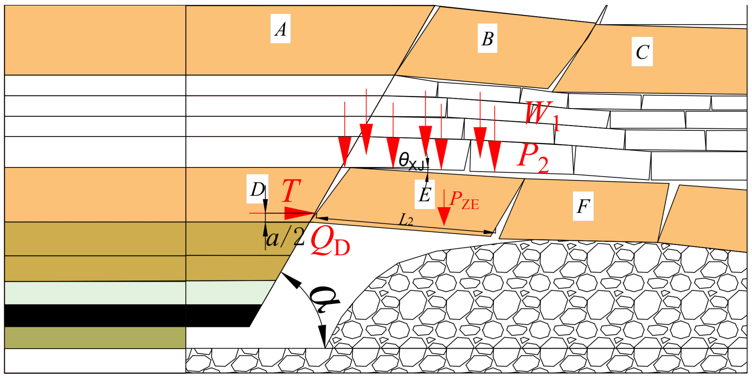
4.2. Mechanical Analysis of Low Bearing Structure

As mining progresses, the lower key layer fractures, forming a “masonry beam” structure adjacent to the goaf. The presence of a short cantilever beam shape in the roof above the coal pillar on one side of the goaf leads to rotary instability of key block E above the coal pillar, as observed in physical similarity simulation experiments, resulting in the formation of an “articulated” structure. This structure exerts pressure on the top of the coal pillar, resulting in its failure under the overlying load. Consequently, a model of the low-bearing structure is established and analyzed through similar simulation experiments, as depicted in Figure 7.
Once the overlying strata have stabilized, the load RXJ on the low-hinged structure of the coal pillar is primarily comprised of the self-weight W1 of the overlying strata, the load transmitted by key block E, and the load transmitted by high key block B. This results in the following expression:
R XJ = W 1 + P 2 + P Z E
In the formula, P2 is the load transferred by the high key block B, kN; PXJ is the load transmitted by the low key block E, kN.
The load W1 of overlying strata on the coal pillar is as follows:
W 1 = [ ( L + a ) H + 1 2 H 2 cot θ X J ] γ 1
In the formula, γ1 is the average density of overburden, kN/m3.
The self-weight force PXJ of the key block E is as follows:
P XJ = L 2 γ 3 h 2
In the formula, γ3 is the average bulk density of the low key stratum, kN/m3; h2 is the thickness of low key strata, m.
Under the influence of mining disturbance, the interlayer rock layers between the key layers are broken, and the load P2 is applied to the lower key layer as follows:
P 2 = L 2 γ 4 h i
In the formula, γ4 is the average bulk density of interlayer rock, kN/m3; h i is the thickness of the interlayer rock layer, m.
When the low key stratum breaks to form a “hinged” structure, the force WXJ is as follows:
W XJ = Q D = 4 i 2 ( 1 sin θ XJ ) 3 sin θ XJ cos θ XJ 4 i 2 + 2 sin θ XJ ( cos θ XJ 2 ) R XJ
By substituting Equation (6) into Equation (10), we obtain the following:
W XJ = Q D = 4 i 2 ( 1 sin θ XJ ) 3 sin θ XJ cos θ XJ 4 i 2 + 2 sin θ XJ ( cos θ XJ 2 ) × ( W 1 + P 2 + P XJ )
In the formula, i2 is the block size of the key block B in the key layer, i2 = h2/L2. In the formula, i2 is the block size of the key block B in the key layer, i2 = h2/L2; the θSJ is the key fast rotation angle of the upper key layer “hinged” structure B, (°); and the θXJ is the key fast rotation angle of the lower key layer “hinged” structure E, (°).

4.3. Load Calculation of “Hinged-Hinged” Structure in Overlying Strata of Coal Pillar

The combined structural load PZ is calculated using the “hinged-hinged” structural mechanics model. To simplify the calculation process, parameters for the “hinged-hinged” composite structure are assigned, combining measured mine site data and indoor experimental research. The rotation angles θXJ = 3° and θXJ = 5° between the key block E and key block B in the high and low key layer breaking structure are considered.
The load PZ of the “hinged-hinged” composite structure is as follows:
P Z = W 1 + R S J + R X J
The load of (7)~(9) into the available coal pillar is as follows:
P Z = [ [ ( L + a ) H + 1 2 H 2 cot θ xj ] + [ 4 i ( 1 sin θ Sj ) 3 sin θ Sj cos θ Sj 4 i + 2 sin θ Sj ( cos θ Sj 2 ) × ( P 1 + P ZB ) + 4 i ( 1 sin θ XJ ) 3 sin θ XJ cos θ XJ 4 i + 2 sin θ XJ ( cos θ XJ 2 ) × ( W + P 2 + W XJ ) ] ]
In the formula, Pz is the load on the coal pillar, MPa.

4.4. Reasonable Width Calculation of Coal Pillar

Given that the load applied to the coal pillar width remains below its ultimate strength, the calculation of a suitable coal pillar width is determined using Mark Bieniaski’s formula for coal pillar strength.
σ P = σ c ( 0.64 + 0.54 L b )
In the formula, B is the height of the roadway, m, and L is the width of the coal pillar, m.
In the state of limit equilibrium for the coal pillar, the calculation formula for coal pillar width can be derived from the calculation of overburden load as follows:
σ P = P Z 1000 L
According to formulas (13)–(15), the width of the coal pillar can be obtained as follows:
[ [ ( L + a ) H + 1 2 H 2 cot θ x j ] + [ 4 i 2 ( 1 sin θ S j ) 3 sin θ S j cos θ S j 4 i 2 + 2 sin θ S j ( cos θ S j 2 ) ( P 1 + P Z B ) + 4 i 1 ( 1 sin θ X J ) 3 sin θ X J cos θ X J 4 i 1 + 2 sin θ X J ( cos θ X J 2 ) ( W 1 + P 2 + P X J ) ] ] 1000 L = σ c ( 0.64 + 0.36 L b )
In the formula, H represents the buried depth of 370 m; h denotes the average mining height of 4.5 m. The lengths of key blocks B and E are specified as L1 = 17.3 m and L2 = 14.7 m, respectively. The key blocks are characterized by i1 = 1.38 and i2 = 1.28; the load transfer coefficient KG is set to 0.8. As per the development height data of the water-conducting fractured zone, the upper load rock layer thickness for key blocks B and C is estimated at h1 = 23.88 m and h2 = 18.82 m, respectively. The roadway dimensions are specified as a width of 5.0 m and a height of 3.75 m. Given the No.5 coal seam’s weak nature at Anyang Coal Mine, a prudent coal pillar width of 15 m is determined using σ c = 18 MPa and integrating these values into formula (16).

5. Engineering Application

Based on physical similarity simulation experiments and theoretical analysis, the coal quality at Anyang Coal Mine is characterized by soft rock and is adversely affected by the thick overlying loess layer, leading to a diminished bearing capacity of the coal pillar. A reduction in coal pillar width corresponds to a gradual increase in vertical stress per unit area, leading to noticeable deformations on the sides of coal pillars within the working face’s return airways.

5.1. Roadway Support Parameters

The return airway of the 1513 working face features an arched roadway with an excavation width of 5000 mm and a roadway height of 3750 mm. With an original coal pillar width of 30 m in the return air roadway, the roadway remained generally stable despite being affected by stress advance within 75 m of the working face, resulting in some deformation, albeit without significant impact on the entire roadway. Thus, to maximize economic benefits and ensure roadway stability during tunneling and working face production, the coal pillar width is optimally adjusted under the original support conditions, as illustrated in Figure 8.

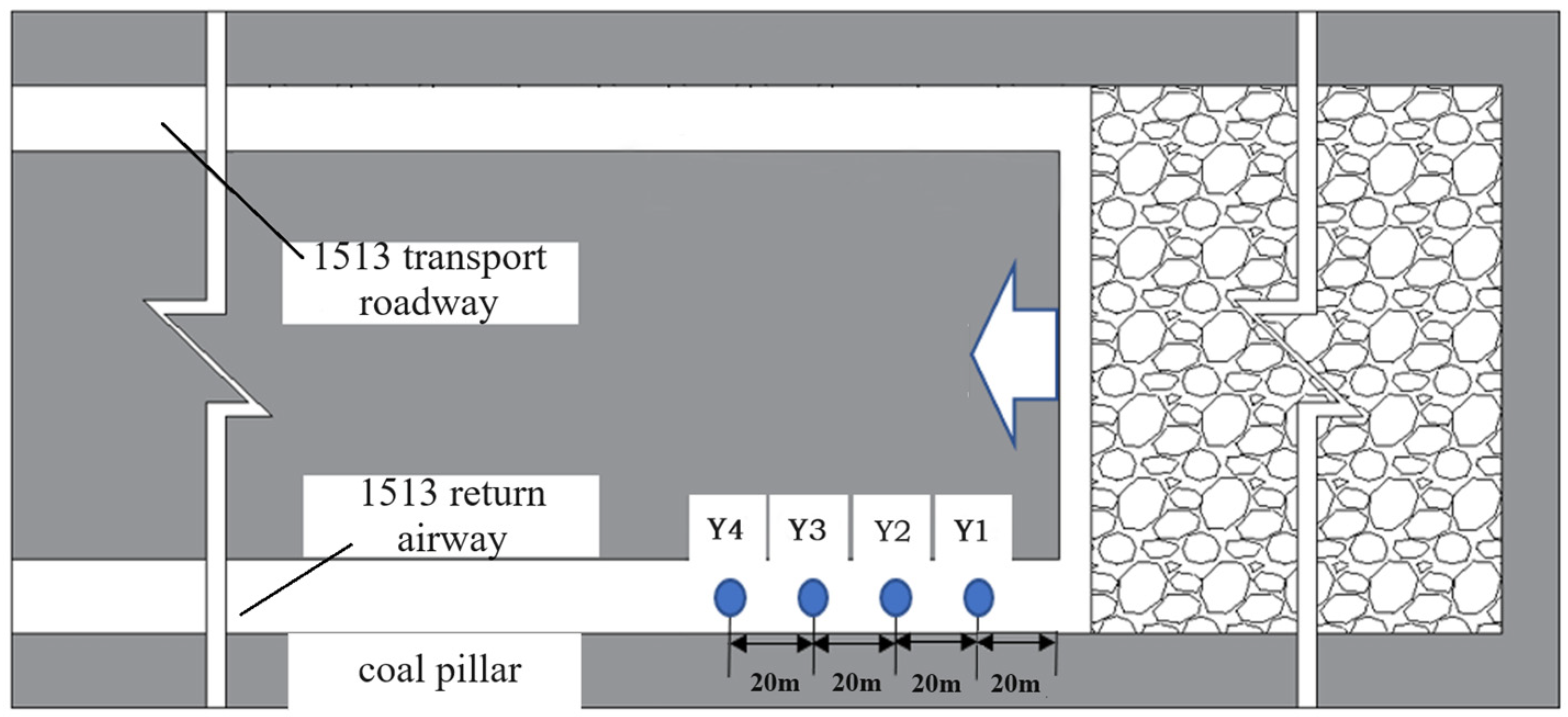
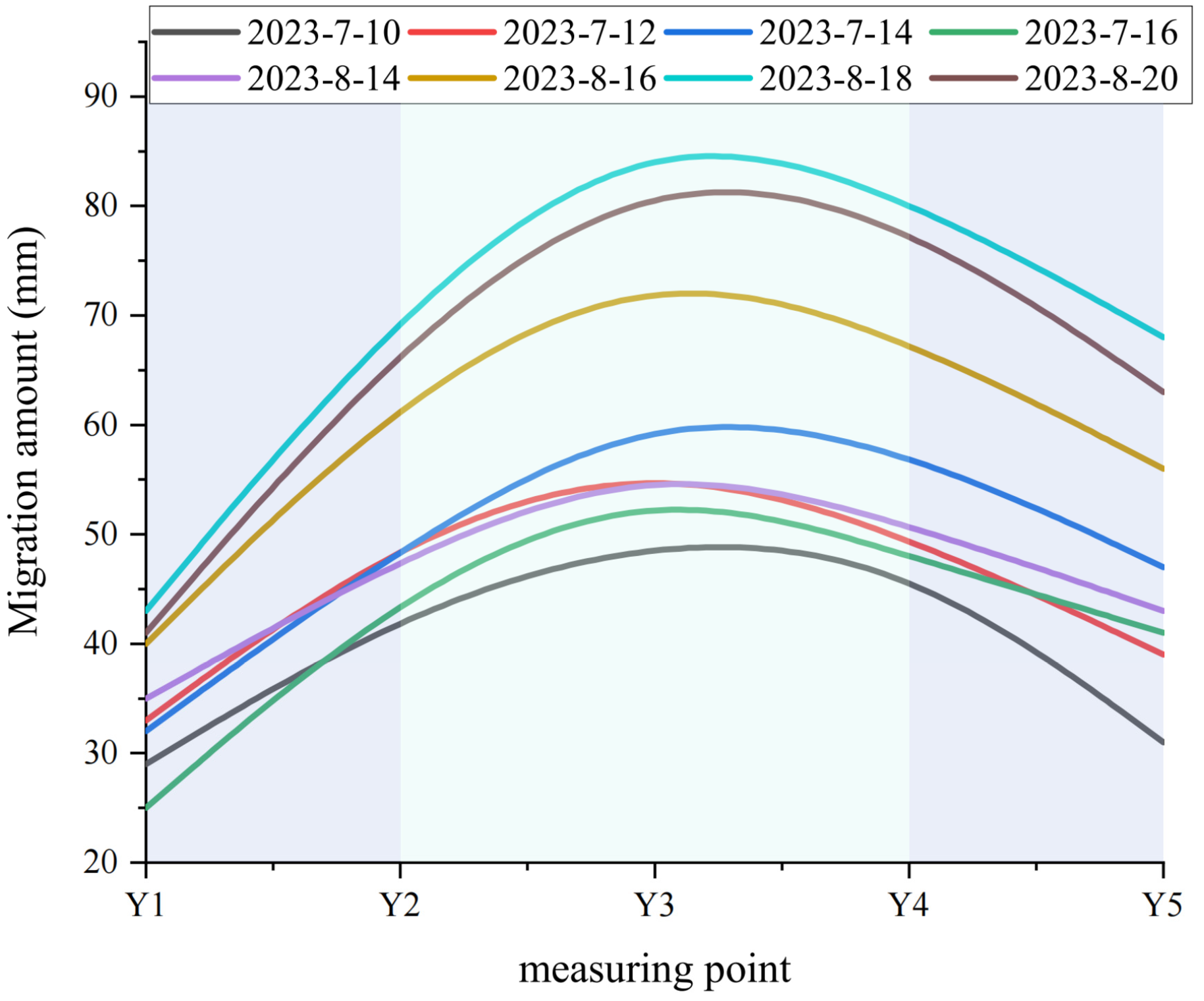
5.2. Filed Monitoring and Analyzing

Engineering field monitoring is utilized to analyze the deformation of surrounding rock in the roadway, aiming to verify the scientific reliability of the research results and enhance coal recovery rates. To monitor real-time roadway deformation during the mining of the 1513 working face, a 100 m section of roadway was chosen. The 100 m roadway was equipped with five stations spaced 20 m apart. Monitoring was conducted on the roadway of the mine’s 1513 working face. Figure 9 illustrates the location of the specific monitoring station.
The deformation monitoring of the surrounding rock of the roadway before and after reducing the coal pillar width is illustrated in Figure 10. Reducing the coal pillar width increases the deformation of the working face during mining, with the displacement at Y2 and Y3 stations being the most significant. The deformations at Y2 and Y3 stations on both sides of the roadway are 71 mm and 88 mm, respectively, with average displacements of 62.2 mm and 76 mm. Before reducing the coal pillar, the maximum displacements at Y2 and Y3 were 50 mm and 62 mm, respectively, with average displacements of 45.4 mm and 54.4 mm. Thus, compared to the original coal pillar width, roadway deformation increases by approximately 41–42%, with the narrower coal pillar exhibiting more deformation than the 25 m-wide pillar.
On-site data analysis reveals that the coal pillar, affected by the “hinge-hinge” structure, shows greater deformations at Y2 and Y3 stations in the return airway. Conversely, stations experience lesser deformation owing to reduced stress impact on the coal pillar. These observations suggest that stable coal pillar conditions ensure safe production at the mine.

6. Discussion and Conclusions

In the process of physical similarity simulation tests, human factors prevent the complete simulation of the natural physical and mechanical properties of rock strata. Additionally, considering the time effects at the actual mine site, there are inherent limitations in the physical similarity simulation test. As a result, the test outcomes may differ slightly from the actual site phenomena. However, monitoring field data from the coal mine shows that the test results are largely consistent with real-world conditions. Therefore, despite its limitations, the physical similarity simulation experiment can effectively reflect the mine’s actual conditions and serve as a valuable tool for addressing mining challenges.
(1)
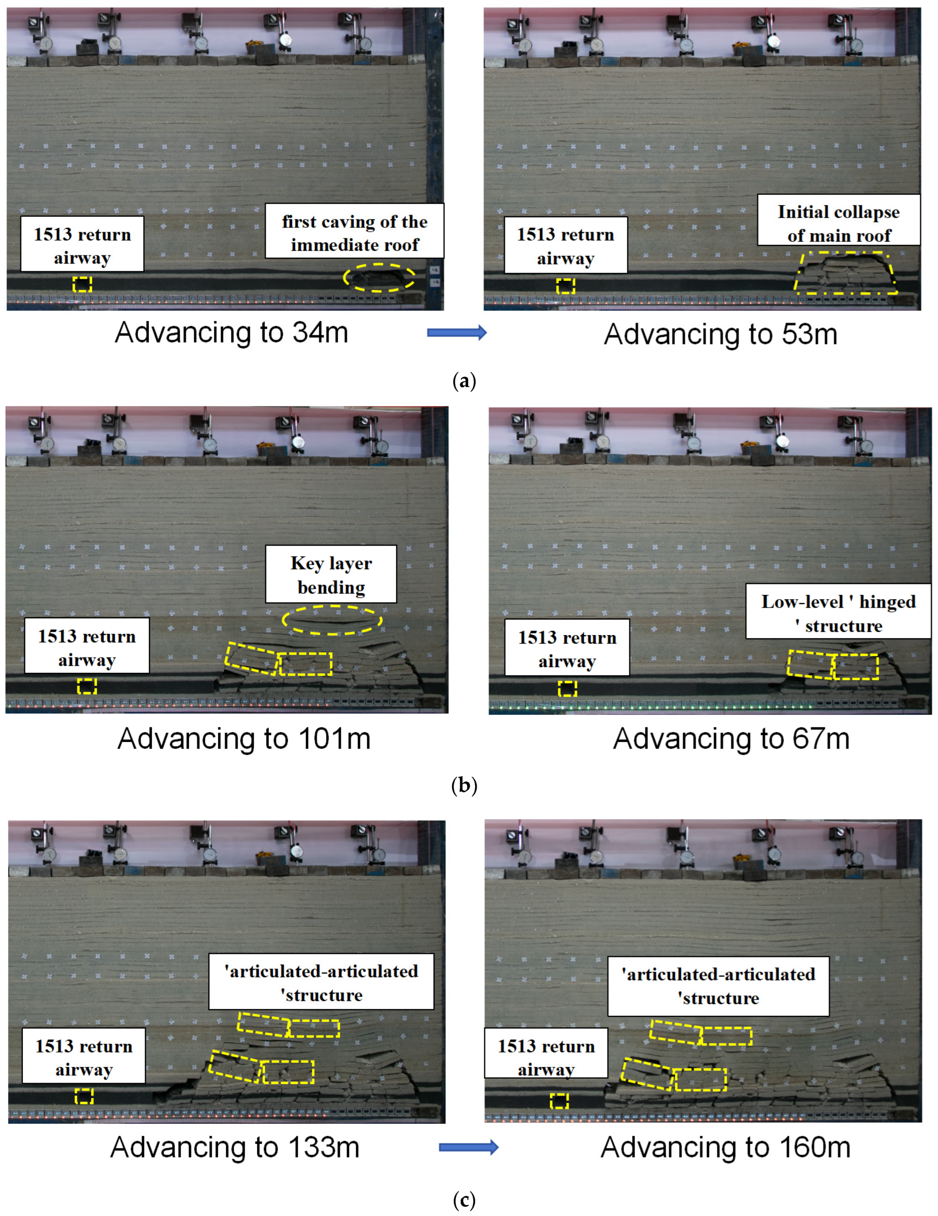
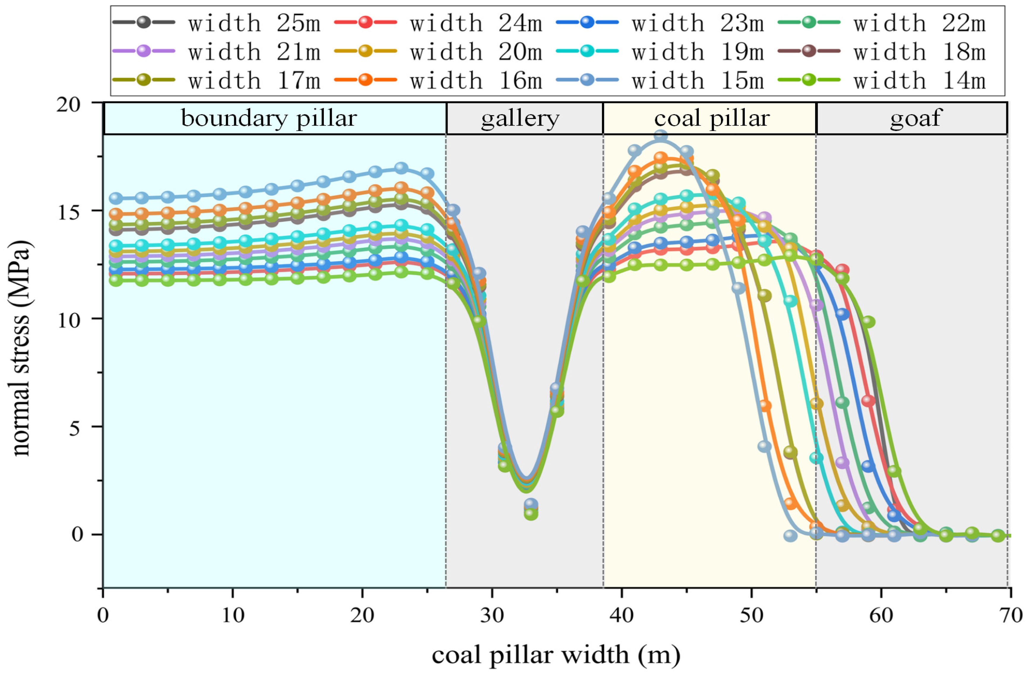
Based on the physical similarity model at a scale of 1:100, the experimental results demonstrate that during the reduction of the coal pillar, the overlying bearing layer fractures and forms a “hinged” structure. Consequently, the coal pillar bears an increased load from the overlying strata. As the coal pillar continues to narrow, the upper key stratum also fractures under the influence of mining, resulting in a “hinged-hinged” combination composed of the upper and lower key strata. This combined structure impacts the coal pillar. According to stress data from the floor stress meter, reducing the coal pillar width from 25 m to 14 m significantly increases the stress to 19.4 MPa. Given that the No. 5 coal seam at Anyang Coal Mine is a soft coal seam, an insufficient coal pillar width leads to concentrated stress on the side of the roadway coal pillar, potentially causing significant deformation and the risk of partial collapse. Therefore, the coal pillar width is ultimately determined to be 15 m.
(2)
Based on the results of the physical similarity simulation test and the geological conditions of Anyang Coal Mine, a mechanical model of the coal pillar-bearing structure was established. The forces acting on the coal pillar were analyzed using a high and low “hinged” structure model, leading to the development of a “hinged-hinged” combination to calculate the load on the overlying strata. Using the load calculation results of the double “hinged” bearing layer structure and applying Mark Bieniawski’s coal pillar strength calculation formula, the optimal coal pillar width was determined to be 20 m.
(3)
Field monitoring data indicate that reducing the coal pillar width from 25 m to 20 m, resulting in significant deformation on the side of the coal pillar in the 1513 return airway. With support strength unchanged, the displacement on both sides increases by 41–42% compared to the original coal pillar width. However, the maximum displacement is observed 40 m to 60 m ahead of the working face, with relatively minor deformation at other locations. Thus, with stable coal pillars, safe production in the mine can be ensured. Additionally, these findings can provide guidance and reference for mines with similar geological conditions.

Author Contributions

Conduct field research on Y.Z., R.B., Y.H., Y.Y., P.L., H.W., J.S. and H.P.; Y.Z. manuscript writing; similar simulation experiments include Y.Z., H.W., J.S. and H.P.; writing review and correction of T.Y., J.Z. and H.L. All authors have read and agreed to the published version of the manuscript.

Funding

This study was supported by the National Natural Science Foundation of China, which was chaired by Associate Professor Yang Tao and Professor Zhang Jie, (no. 52004200 and no. 51774229). Thank you very much for the support of the National Natural Science Foundation project.

Institutional Review Board Statement

Not Applicable.

Informed Consent Statement

Not Applicable.

Data Availability Statement

The relevant data of this manuscript are obtained from field measurements and tests, which are real and effective.

Acknowledgments

Thanks to Yiming Zhang, Jie Zhang, Haifei Lin, and Ruoyu Bao for their technical help in collaborating on the experimental work. I would also like to thank Yifeng He, Yihui Yan, Pengkun Luo, Haohao Wu, Jianping Sun, and Haibo Pang for providing helpful inspiration, suggestions, guidance, review, and supporting work.

Conflicts of Interest

The authors declare no conflicts of interest.

References

  1. Kang, H.P.; Yi, K. Simulation study on dilatant and rheologic properties of soft rocks surrounding deep roadway and its application. J. China Coal Soc. 2023, 48, 15–33. [Google Scholar] [CrossRef]
  2. Bai, J.B. Surrounding Rock Control of Gob-Side Entry Driving; China University of Mining and Technology Press: Xuzhou, China, 2006. [Google Scholar]
  3. Huang, W.P.; Zhao, T.Y.; Jiang, D.H.; Guo, X.S.; Zheng, Y.S.; Wang, X.W. Arrangement of double entry driving with a narrow coal pillar in the middle and stability control technology of surrounding rock. Chin. J. Rock Mech. Eng. 2023, 42, 617–629. [Google Scholar] [CrossRef]
  4. Zhang, J.P.; Liu, L.M.; Liu, C.X.; Wen, G.C.; Li, Q.H.; Sun, D.L.; Shao, J.; Zhang, J.; Sun, L.Q.; Di, G.Q. Research and application of new prestressed anchor-grouting support for special open-off cut in soft-thick coal seam. J. China Coal Soc. 2021, 46, 3127–3138. [Google Scholar] [CrossRef]
  5. Gao, Y.B.; Wang, Q.; Yang, J.; Ding, W.B.; Fu, Q.; Xu, X.D. Mechanism of deformation and pressure relief control of dynamic gob-side entry surroundings in fully-mechanized caving mining for extra-thick coal seam. Coal Sci. Technol. 2023, 51, 83–94. [Google Scholar] [CrossRef]
  6. Sun, L.H.; Yaang, X.D.; Zhang, H.Y.; Li, X.; Yang, B.S. Experimental research on characteristics of deformation and failure of roadway ribs in soft coal seams under strong dynamic pressure and bolt-grouting reinforcement. J. Min. Saf. Eng. 2019, 36, 232–239. [Google Scholar] [CrossRef]
  7. Wang, G.J.; Jiang, Z.G.; Guo, J.J. Application of numerical simulation to coal mining in seam with soft roof, soft coal and soft floor. Coal Eng. 2019, 36, 232–239. [Google Scholar] [CrossRef]
  8. Li, C.J.; Liu, Y.X.; Gao, H.B.; Xu, Y.Q.; Qiao, Q.F.; Hou, Z.Q. Overlying strata movement and stress distribution law in the “three-soft”coal seam. J. Xi’an Univ. Sci. Technol. 2015, 35, 187–191. [Google Scholar] [CrossRef]
  9. Xu, W.; Wang, E.; Liu, Z.; Hou, E.K.; Wang, S.J.; Deng, Z.S. Research on distribution and evolution patterns of abutment pressure in front of the fully-mechanized working face of “three-soft” coal seam isolated island. Prog. Mine Saf. Sci. Eng. II 2014, 2, 949–955. [Google Scholar] [CrossRef]
  10. Wang, Q.; Pan, R.; Li, S.C.; He, M.C.; Ren, Y.X.; Wang, L.; Ding, G.L.; Sun, H.B.; Jiang, B. Gob side entry failure mechanism and control of bolt-grouting in three soft coal seam. J. China Coal Soc. 2016, 41, 1111–1119. [Google Scholar] [CrossRef]
  11. Jiang, B.; Li, S.C.; Wang, Q.; Pan, R.; Zhang, R.X.; Ren, Y.X.; Wang, D.C.; Ding, G.L.; Jiang, Z.H. Failure mechanism of three soft coal seam roadway and comparison study on bolt and grouting. J. China Coal Soc. 2015, 40, 2336–2346. [Google Scholar] [CrossRef]
  12. Wang, Z.Y.; Lai, X.P.; Liu, X.M.; Cui, F. Construction and application of the GRNN model of coal section pillar width prediction in fully mechanized face. J. Xi’an Univ. Sci. Technol. 2019, 39, 209–216. [Google Scholar] [CrossRef]
  13. Wu, X.; Guo, J.B.; Cui, F.; Wang, Z.Y.; Xu, H.C. PSO-SVM prediction model of coal pillar width in fully mechanized mining face. J. Xi’an Univ. Sci. Technol. 2020, 40, 64–70. [Google Scholar] [CrossRef]
  14. Wang, K.; Lai, X.P.; Guo, B.; Cui, F. Study on the reasonable section coal pillar width for fully mechanized caving face with hard roof and extra-thick coal seam. Coal Eng. 2019, 51, 43–47. [Google Scholar] [CrossRef]
  15. Zhang, J.; Gao, S.S.; Li, T.; Huang, X.P.; Yang, T.; Wang, Z.H.; He, Y.F.; Han, J.B. Study on failure characteristics and control of soft rock roadway floor. Coal Sci. Technol. 2023, 51, 21–28. [Google Scholar] [CrossRef]
  16. Zhang, J.; Li, T.; Gao, S.S.; Huang, X.P.; Wang, L.; Wang, Z.H.; Yan, Y.H. Research on Failure Mechanism and Control of Soft Rock Roadway. Coal Technol. 2023, 42, 1–7. [Google Scholar] [CrossRef]
  17. Zhang, J.; Zhou, F.W.; Yang, T.; Xie, P.; Shen, R.J.; Guo, J.P. Floor heave mechanism and control technique of soft rock roadway in anshan coal mine. Coal Eng. 2019, 51, 37–40. [Google Scholar] [CrossRef]
  18. Zhi, X.X. Study on the characteristics of strata behavior in shallow seam long wall mining under the room-and-pillar mining goaf. J. China Coal Soc. 2012, 37, 898–902. [Google Scholar] [CrossRef]
  19. Zhang, J.G.; Cheng, Z.H.; Chen, H.Y.; Yin, S.F.; Chen, L.; Xue, A. Analysis and optimization of remaining width of coal pillars in the section of Yayaomao coal mine. Coal Sci. Technol. 2022, 50, 60–67. [Google Scholar] [CrossRef]
  20. Cui, F.; Zhang, T.H.; Cheng, X.Q. Research on control of rib spalling disaster in the three-soft coal seam. Shock. Vib. 2021, 2021, 2404218. [Google Scholar] [CrossRef]
  21. Li, S.B.; Wang, L.; Zhu, C.Q.; Ren, Q.H. Research on mechanism and control technology of rib spalling in soft coal seam of deep coal mine. Adv. Mater. Sci. Eng. 2021, 2021, 2833210. [Google Scholar] [CrossRef]
  22. Jiang, Z.S.; Guo, W.K.; Xie, S.R. Coal pillar size determination and surrounding rock control for gob-side entry driving in deep soft coal seams. Processes 2023, 11, 2331. [Google Scholar] [CrossRef]
  23. Qian, M.G.; Shing, P.W.; Xu, J.L. Min Pressure and Rock Formation Control; China University of Mining and Technology Press: Xuzhou, China, 2015. [Google Scholar]
  24. Xu, Z.L. Elasticity; Higher Education Press: Beijing, China, 2006. [Google Scholar]
  25. Wang, H. Study on Width Reservation and Stability of Coal Pillar in 421-2 Face of Chenjiashan Coalmine; University of Mining and Technology: Xuzhou, China, 2021. [Google Scholar]
  26. Guo, L.Q.; Cai, Q.P.; Peng, X.Q. Effect of strength criterion on design of strip coal pillar. Rock Soil Mech. 2014, 35, 777–782. [Google Scholar] [CrossRef]
  27. Zhang, J.; He, Y.F. Research on the fracture evolution law and combined bearing structureload of shallow buried coal seam group. Coal Sci. Technol. 2023, 51, 65–76. [Google Scholar] [CrossRef]
  28. Sun, Q. Effect of Overburden Strata Structure on Reasonable Width of Inter Recovery Room Pillar in Mining Close Distance Seam. Master’s Thesis, Taiyuan University Of Technology, Taiyuan, China, 2020. [Google Scholar] [CrossRef]
  29. Lai, X.P.; Zhang, X.D.; Shan, P.F.; Cui, F.; Liu, B.W.; Bai, R. Study on development law of water-conducting fractures in overlying strata of three soft coal seam mining under thick loose layers. Chin. J. Rock Mech. Eng. 2021, 40, 1739–1750. [Google Scholar] [CrossRef]
Figure 1. Working face layout and section coal pillar diagram.
Applsci 14 06127 g001
Figure 2. Comprehensive histogram of coal (rock) layer.
Applsci 14 06127 g002
Figure 3. Structural characteristics of overlying strata under different mining conditions. (a) Initial stage of excavation. (b) Breaking structure of low key stratum. (c) “Articulated-articulated” composite structure.
Applsci 14 06127 g003
Figure 4. Vertical stress diagram of coal pillars with different widths.
Applsci 14 06127 g004
Figure 5. Mechanical model of coal pillar bearing structure.
Applsci 14 06127 g005
Figure 6. Mechanical structure of high key stratum breaking “hinged” structure.
Applsci 14 06127 g006
Figure 7. Mechanical structure of low key stratum breaking “hinged” structure.
Applsci 14 06127 g007
Figure 8. Roadway support section diagram.
Applsci 14 06127 g008
Figure 9. Roadway measuring point layout.
Applsci 14 06127 g009
Figure 10. Roadway deformation.
Applsci 14 06127 g010
Table 1. Model parameters and material ratio.
Lithologic CharactersThickness of Stratum (m)Bulk Modulus (GPa)Shear Modulus (GPa)Force of Cohesion (MPa)Tensile Strength (MPa)Angle of Internal Friction
(°)
Density
(kg·m−3)
Ratio (Sand:Gypsum:Calcium Carbonate)
kern stone8.507.35.274.143.273225307:4:6
post office box stone7.805.64.382.911.373424607:2:8
medium grained sandstone8.446.304.473.202.563324508:3:7
siltstone17.514.83.371.971.343224507:3:7
kern stone6.237.35.274.143.273225307:4:6
siltstone2.404.83.371.971.343224507:3:7
kern stone2.967.35.274.143.273225307:4:6
sandy mudstone7.233.071.841.60.95220008:3:7
medium grained sandstone6.876.34.473.22.563324508:3:7
siltstone6.174.83.371.971.343224507:3:7
sandy mudstone4.863.071.841.60.95220008:3:7
siltstone5.214.83.371.971.343224507:3:7
post office box stone4.695.64.382.911.373424607:2:8
4 coal1.001.460.450.50.525132020:20:1:5
siltstone1.954.83.371.971.343224507:3:7
5 coal4.505.604.382.911.3734246020:20:1:5
siltstone2.914.83.371.971.343224507:3:7
silicarenite8.067.35.274.143.273225307:4:6
post office box stone2.05.64.382.911.373424607:2:8
Disclaimer/Publisher’s Note: The statements, opinions and data contained in all publications are solely those of the individual author(s) and contributor(s) and not of MDPI and/or the editor(s). MDPI and/or the editor(s) disclaim responsibility for any injury to people or property resulting from any ideas, methods, instructions or products referred to in the content.

