Article

Systematic Concept Study of Brayton Batteries for Coupled Generation of Electricity, Heat, and Cooling

Institute of Engineering Thermodynamics, German Aerospace Centre (DLR), 70569 Stuttgart, Germany
Appl. Sci. 2024, 14(14), 6073; https://doi.org/10.3390/app14146073
Submission received: 8 May 2024 / Revised: 3 July 2024 / Accepted: 8 July 2024 / Published: 12 July 2024
(This article belongs to the Section Applied Thermal Engineering)

Abstract

:
This study presents a systematic analysis of Brayton batteries using Ebsilon Professional® simulations. Over 200,000 concept configurations were evaluated, with less than 1% proving physically feasible. The research aimed to assess electricity generation; coupled generation of electricity and heat; coupled generation of electricity and cooling; and coupled generation of electricity, heat, and cooling, all with or without waste heat integration. Efficiency ranged from 20% to 50% for electricity generation alone, with higher efficiencies at a compressor discharge temperature of 625 °C compared to 450 °C. Co-generation improved the overall efficiency, although at the expense of power efficiency. Notably, simultaneous electricity, heat, and cooling generation solutions were absent within the study’s parameters. Lead concepts, predominantly air-based systems with or without charging line recuperators and heat exchange at various stages, were identified. These will undergo detailed dynamic system simulations, focusing on thermal energy storage. Comparison with the existing literature was limited due to differing parameters and topologies, highlighting the value of this systematic analysis in identifying optimal solutions.

1. Introduction

The global push of the energy transition is leading to a shift away from conventional thermal power plants towards innovative concepts that supply climate-neutral energy in the form of electricity, heat, or cooling by efficiently utilizing renewable electricity and the integration of thermal energy storage systems. Carnot batteries are one of these innovative concepts that have been the subject of increased scientific research in this context for several years, with the majority of the literature focusing on pure electricity storage systems.
“Carnot Batteries are an emerging technology for the inexpensive and site-independent storage of electric energy at medium to large scale. Also referred to as “Pumped Thermal Electricity Storage” (PTES) or “Pumped Heat Storage” (PHES), a Carnot Battery transforms electricity into thermal energy, stores the thermal energy in inexpensive storage media such as water or molten salt and transforms the thermal energy back to electricity as required.” [1].
One possible implementation of a Carnot battery uses the Joule or Brayton process, which operates with gaseous working fluids. This system, known as a Brayton battery, comprises two sets of turbomachinery (a turbine and a compressor) and two thermal storage systems at different temperature levels. These elements work together in a coupled cycle, as illustrated in the flow diagram in Figure 1a.
During the charging process (left part of the flow diagram), a motor drives the compression of the working fluid in a turbo compressor or blower, increasing its temperature, as shown in the T-s diagram in Figure 1b (counterclockwise in blue). The heated working fluid then transfers thermal energy to the high-temperature thermal energy storage (HT-TES) system. Afterward, the cooled working fluid moves to the turbine, where it expands and cools down while generating energy through a generator. The fluid then heats up again in the low-temperature thermal energy storage (LT-TES) system.
In the discharging process (right part of the flow diagram), the cycle reverses, as depicted in the T-s diagram (clockwise in red). Electrical energy is supplied during the charging phase and discharged during the discharging phase.
In theory, Brayton batteries can achieve very high round trip efficiencies (RTEs) if ideal components (component efficiencies = 100%) or very high process temperatures (>>1000 °C) are assumed. However, this is not practically achievable with current technology. RTEs in the range of 40 to 50% are more realistically achievable. During the charging and discharging cycles, a considerable amount of energy is converted into heat, which either cannot be utilized at all or only partially, especially when the system is used solely for electricity generation. This heat needs to be dissipated from the process, which is usually provided for during charging before the turbine or during discharging after the compressor. In principle, this can be achieved at different points, but it has not been systematically investigated so far. Generally, there are numerous theoretical studies on Brayton batteries in the literature, which are summarized in the following section. This summary focuses on subcritical processes. Essentially, this summary is based on the review papers by Olympios et al. [2], Dumont et al. [3], and Novotny et al. [4], supplemented by other important publications.
Most concepts envisage a closed-loop system, but there are exceptions. Weissenbach [5], for example, proposed an open-loop system using air as the working fluid in a patent in 1979, where air is compressed to 800–900 °C, and the heat is stored in ceramic spheres in steel pipes. In the years 2008–2009, SAIPEM [6] and Isentropic Ltd. [7] each presented concepts based on a closed-loop argon cycle. SAIPEM proposed using maximum temperatures between 1000 °C and 1500 °C and storing thermal energy in bricks made of refractory material. Axial turbomachinery was used for compression and expansion, requiring a total of four machines. Isentropic Ltd. developed a cycle with lower maximum temperatures of around 500 °C and envisaged using a bed of spheres as the storage inventory. The beds can be “segmented” to improve performance and flexibility. Isentropic Ltd. developed reciprocating machines that could be operated as both compressors and expanders [8]. A 150 kW Brayton cycle was successfully tested in 2019 [1,8]. Recently, Malta Inc. has begun developing a regenerative closed-loop system [9,10]. Malta Inc.’s goal is to use commercial or near-commercial technologies for each component [11]. Air-based turbomachinery is used for compression and expansion, and temperatures are kept below 600 °C to control steel costs. A molten salt storage system is used for the hot storage, while a coolant such as glycol or isopropanol is provided for the cold storage. GridScale [12], developed by the Danish company Stiesdal, is a scalable concept for electrical storage that utilizes a reversible closed Brayton battery using natural stone beds as thermal storage, aiming to balance the production of photovoltaic and wind farms. Stiesdal’s GridScale project, supported by various partners including Andel, Aarhus University, and the Technical University of Denmark, plans a demonstration project in Rødby, Denmark, with a charging/discharging capacity of 4 MWe/2 MWe and a storage capacity of 10 MWhe. Enolcon GmbH and Storasol GmbH [13] are also developing a closed-loop Brayton battery, which can optionally be supplemented with an ORC cycle to increase RTE. Proof-of-concept is currently being developed, aiming to achieve an RTE of about 40–45%. There are plans to develop reversible turbomachinery with nitrogen as the working fluid in collaboration with Atlas Copco to achieve higher pressures and temperatures, thus achieving an RTE of about 63–67%.
Simple system models for Brayton batteries with ideal gasses can be established analytically, and several correlations have been developed, see for example [14,15,16,17,18]. These correlations typically illustrate the significance of certain parameters for the efficiency of the cycle process, which is particularly sensitive to the isentropic or polytropic efficiency of the compression and expansion machinery. Another important parameter is the pressure ratio, which represents the ratio between the compression and expansion work during the charging process, with larger values improving the electricity-to-electricity efficiency [19]. Brayton batteries have relatively low pressure ratios, and the design of efficient compressors and expanders is necessary to achieve reasonable cycle efficiencies. The simplest implementation of a Brayton battery is shown in Figure 1, but different technologies and materials can be used in each phase of the process, leading to a variety of concepts proposed in the literature.

1.1. Open vs. Closed Configurations

Brayton batteries can be operated in open or closed systems. Open systems intake air from the environment and release it, reducing investment costs due to unnecessary heat dissipation components. Closed systems require heat dissipation components and enable operation under pressure, increasing the power density of the compression and expansion machinery. The choice of working fluid in a closed loop depends on the configuration, with fluids with high specific heat capacity (cp) and low isentropic exponent (κ) being preferred when direct thermal storage is used. Closed loops offer flexibility in temperatures during different loop phases and allow for a higher temperature ratio, reducing the size of thermal storage. Partial load operation in closed loops can be regulated by adjusting the fluid mass flow rate. This allows for flexible operation over a wide range of charging and discharging powers without significant impact on overall efficiency. To compensate for temperature differences between charging and discharging cycles, heaters and coolers can be used. This dissipates the heat generated by irreversibilities to the environment, allowing the storage to operate in a cyclic manner.

1.2. Thermal Energy Storage

The most suitable thermal storage systems for integration into Brayton batteries are based on sensible storage materials, with many concepts proposing the use of solid media. Solids can be used over a wide temperature range, have relatively high volumetric heat capacities, and are cost-effective and abundant. However, the working fluid of the cycle flows directly through these storage systems, which may require them to be pressurized, significantly increasing investment costs. Thermal fluctuations also lead to additional stresses in the containers, known as thermal ratcheting [20], which must be considered in the design.
Solid media storage systems are characterized by a thermal gradient along the length of the storage. This poses several challenges for the design and operation of Carnot batteries. Firstly, the thermal gradient implies that it is not possible to fully charge the storage system without a significant drop in the temperature of the exiting fluid [21,22]. Therefore, the storage must be oversized to achieve the required storage capacity. Secondly, the fluctuations in the outlet temperature can have effects on the rest of the cycle, potentially requiring regulation [23]. These issues can be mitigated through various design changes, such as incorporating electric heaters and heat dissipation devices [24] or providing a bypass to the storage, allowing for a constant mixing temperature during discharge [25].
Using a liquid phase as a storage medium requires indirect heat transfer from the primary circuit to a storage circuit via a heat exchanger. Depending on its vapor pressure, the fluid may not need to be pressurized, reducing the costs of the storage tanks. Typical liquids, such as molten salt or thermal oil, have a limited operating temperature range and may degrade over time. Some relevant liquids are widely used in CSP (Concentrated Solar Power) plants. Therefore, Brayton batteries can benefit from these operational experiences and cost reductions. According to current technology, nitrate salt melts are limited to maximum temperatures below 565 °C due to salt degradation. However, recent developments in tank technology may allow the salt to be stable at temperatures up to 600 °C [26].

1.3. Compression and Expansion Machines

Isentropic Ltd. has developed positive displacement machines that can operate as both a compressor and expander, reducing the number of machines from four to two. However, these machines require custom designs with a large bore-to-stroke ratio and are more suitable for smaller capacities (<5 MWel). A prototype developed by Isentropic Ltd. and the University of Newcastle achieved efficiencies of 92–94% [2]. Axial turbomachinery is more cost-effective and efficient for larger capacities (>50 MWel) and is better suited for larger installations. Conventional turbomachinery is either a compressor or an expander. The reduction in the number of machines from four to two also offers potential cost savings, although it is not yet the current state of the art. The outlet temperature of the charging compressor is the highest temperature in the cycle process and simultaneously presents one of the greatest technical challenges in the development of the sub-components and thus for the overall Brayton battery system.

1.4. More Complex Concepts

Various modifications of Brayton batteries have been proposed in the literature, including the utilization of cryogenic waste heat [27] or electric heaters to adjust the compressor outlet temperature [28,29]. One approach integrates electric heaters into the charging process to reduce the compressor pressure ratio and costs [28]. A similar system attempts to utilize excess heat during discharge, improving overall efficiency [30]. Supercritical carbon dioxide (sCO2) offers advantages due to its high density and the compactness of turbomachinery, but the heat-to-work ratios require efficient heat transfer [11]. Despite operating at high pressures, sCO2 Brayton batteries are similarly efficient to Brayton batteries with ideal gasses [2].

1.5. Conclusions for the SWS-SYS Project

Although Brayton batteries are a widespread research topic, there are no comprehensive systematic studies on their topology. Only individual systems or a few different systems are compared, but not the many different possibilities for the exact design regarding the introduction or extraction of heat from the system. While the systems considered in the literature include heat exchangers at various points in the system, a rationale for the specific design is not provided.
The aim of the present work is therefore to conduct a comprehensive structural concept study with the aim of obtaining Brayton batteries that are simple yet efficient with few components. For this purpose, two different stages of development are considered: compressors at the state of the art (450 °C compressor outlet temperature) and a realistic and near-term achievable development stage for compressors (625 °C compressor outlet temperature) with moderate investment costs. Above 625 °C, cooling of the rear compressor blades or the use of very cost-intensive nickel alloys, as in gas turbines, is necessary [31,32]. Although the use of reversible turbomachinery, i.e., using compressors and expanders for both the charging and discharging processes, involves a significant reduction in components, this is not investigated here. Firstly, this is not the current state of the art, and secondly, there are no model descriptions of the physical behavior that would not require detailed design details [33]. Furthermore, it is questionable whether such units would actually lead to cost reductions, as the construction of such machines, assuming high efficiencies in both directions, would certainly be significantly more complex.
The objectives of the study are to identify favored system designs through a comprehensive techno-economic evaluation of system configurations. One focus is on identifying additional flexibility options (e.g., sector coupling, industrial processes, district heating extraction, cooling provision, waste heat utilization, etc.) compared to pure electricity storage operations.

2. Methods

2.1. Boundary Conditions and Assumptions

To maximize the efficiency and benefits of a Brayton battery, the following options are considered in the present study:
  • Pure electricity generation;
  • Pure electricity generation with waste heat integration;
  • Coupled generation of electricity and heat;
  • Coupled generation of electricity and heat with waste heat integration;
  • Coupled generation of electricity and cooling;
  • Coupled generation of electricity and cooling with waste heat integration;
  • Coupled generation of electricity, heat, and cooling.
The system requirements for each purpose of the plant are defined below. This focuses on the necessary parameters, namely the duration of electricity, heat, or cooling supply, time-of-day restrictions, and temperature levels. Furthermore, a distinction is made between the summer half-year (see Table 1) and the winter half-year (see Table 2).
These system requirements are based on the respective needs or external constraints:
  • During the summer half-year, the electricity input results from the high solar share between 8 am and 4 pm [34], while in the winter half-year, it is due to the nighttime reduction in electricity demand between 10 pm and 6 am.
  • Process waste heat from industry occurs around the clock—both in winter and sum-mer. Here, a temperature level of 90 °C is deliberately chosen, which is typically not utilized because there is no recipient available. Sources include cooling circuits from compressed air generation systems, for example. But also, alkaline electrolysis could be a possible source. [35]
  • Process heat also needs to be supplied around the clock. The temperature level of 250 °C is deliberately chosen to be ambitiously high.
  • For the supply of cooling, air conditioning of shopping centers and office buildings is chosen as the sink. The time restrictions arise from the usual opening and office hours. The temperature levels for supply and return are taken from [36].
For the intended concept comparison, it is necessary to define a basic topology. This is already given by the flow diagram in Figure 1a, which, however, is supplemented by optional heat exchangers for heat injection and extraction between the obligatory components (turbomachinery and heat storage).
Also necessary for a consistent comparison is the specification of assumptions and a uniform parameter set for the stationary system simulations. These are as follows:
  • States according to the ideal gas law;
  • No consideration of pressure and heat losses;
  • Temperature after compressor of the charging line: 625 or 450 °C;
  • Pressure after the turbines: 1 bar;
  • Isentropic efficiency of turbomachinery: 0.9;
  • Mechanical efficiency of turbomachinery: 0.99;
  • Electrical efficiency of motors: 0.97;
  • Mechanical efficiency of motors: 0.998;
  • Electrical efficiency of generators: 0.99;
  • Efficiency of TESs: 0.95;
  • Effectiveness of recuperator heat exchangers: 0.9;
  • Gradients for the optional heat exchangers for heat input/output: 10 K;
  • Ambient temperature: 15 °C.
To evaluate the efficiency of the Brayton batteries, the following definitions in Figure 2 apply for the efficiency, respectively, the round trip efficiency (RTE), or the round trip utilization (RTU), as these are storage systems.
When calculating the value for RTU, electricity and heat are valued equally, which is common in the evaluation of combined heat and power (CHP) systems such as cogeneration units. Furthermore, only usable heat flows are included in the balance; this applies to both discharged and supplied heat flows. The integration of waste heat or heat from the environment is not taken into account.

2.2. Design of Suitable System Configurations

The objective of this task is to systematically design suitable system configurations based on the chosen topology. All theoretically possible integration points for heat exchangers for heat extraction or supply into the plant were systematically investigated through system simulations using the Ebsilon Professional® software, version 16, developed by Iqony Solutions GmbH, based in Essen, Germany. The created universal system simulation tool is depicted in Figure 3 and represents the flow diagram from Figure 1a, supplemented with optionally switchable heaters and coolers between the mandatory main components.
The following variations were analyzed:
  • Closed and open cycles.
  • Compressor outlet temperature CDT of the charging line (manipulated variable): 450 °C (state of the art for turbo compressors) or 625 °C (a realistically achievable and economically justifiable development stage). The compressor outlet pressure serves as the control variable here. The Ebsilon Professional component 39 (controller with internal target value) is used here.
  • Working fluids: air, as well as CO2 and argon for the closed concepts.
  • For the air-operated system, variants with a recuperator for transferring the heat from the hot to the cold side of the charging line (and optionally the discharging line) were also considered.
Additionally, the idea of providing other technologies for expansion and compression such as screw or piston machines was considered. However, a literature review revealed that axial turbomachinery is indispensable for the desired operating range (high power at moderate pressures) [37].
The investigation of concepts based on reversible units, which avoid separate cycles for charging and discharging, was also considered. However, such turbomachinery is not state of the art. A literature review on the modeling of reversibly operating turbomachinery has only yielded the work of Zehner [33]. The model equations contained therein require detailed knowledge of the construction of the turbomachinery used, making it impossible to create a generic model suitable for system simulations. Since turbomachinery can only be optimally designed for one flow direction, the use of reversible machines also carries the disadvantage of significantly lower efficiency, which likely outweighs the theoretical advantage of potentially lower investment costs in the case of Brayton batteries, as Brayton batteries already have limited efficiency potential in a realistic, non-idealized consideration.
Therefore, the focus was limited to systems based on turbomachinery, and separate circuits for charging and discharging are provided.
The resulting concept matrix, which was worked through by multiple system simulations, is presented in Table 3.
The coolers C and heaters H, which are arranged between the main components in Figure 3 and can optionally be activated by on/off switches in value inputs (Component 46 in Ebsilon Professional), were combined using the following combinations and calculated using time series: 1C∨1H, 2C∨2H, 1C∧1H, 1C∧2H, 2C∧1H, 2C∧2H.
By using the formula from combinatorics, a subset of probability theory, for “drawing without replacement”, we arrived at a total of 202,814 different concepts:
n k = n ! n k ! k !
Considering the fixed parameter set, just under 1145 individual concepts were found to be physically feasible (less than 1%), which were evaluated based on the specific purpose requirements as outlined below.

3. Results

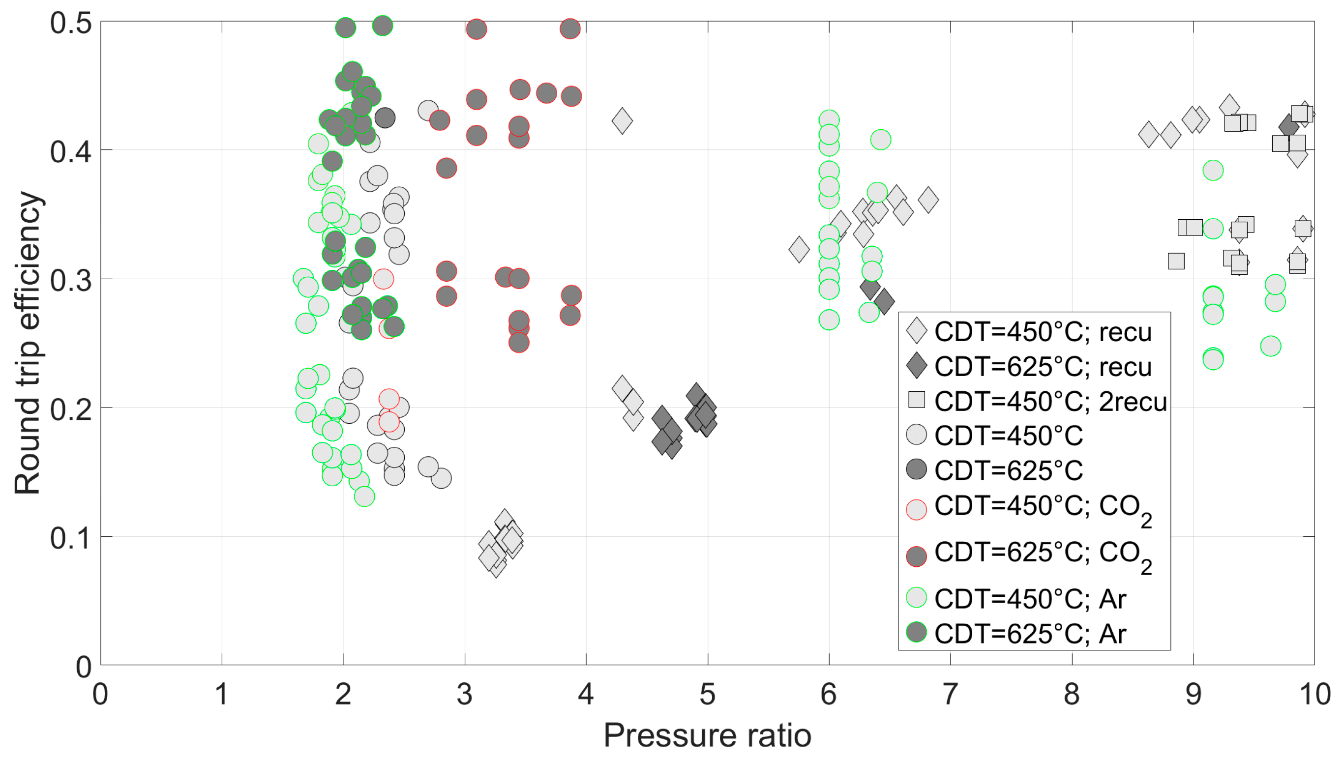
3.1. Power Generation with or without Waste Heat Integration

In Figure 4, the round trip efficiency (RTE) is plotted against the compressor pressure ratio (Π) for power generation with or without heat integration. Each marker represents a concept, with lighter markers indicating a lower compressor discharge temperature (CDT) of 450 °C and darker markers indicating a CDT of 625 °C. The markers outlined in red represent concepts using CO2 as the working fluid, while those outlined in green represent concepts using Argon. Square markers represent concepts with a recuperator, while diamonds indicate concepts with a recuperator only in the charge line, and squares indicate concepts with a recuperator in both the charge and discharge lines for transferring heat from the hot to the cold side.
The range of calculated RTE values is between 20 and 50%. The diagram also includes concepts that exhibit very high pressure. These result from low compressor inlet temperatures, where cooling to ambient temperatures is applied, for example, and the simultaneously relatively high specified compressor discharge temperature of 625 °C. This can be easily explained thermodynamically using the isentropic equation, especially for the working fluid CO2. However, in addition to the high pressure ratio, these solutions exhibit low RTE values. In the search for promising concepts, it is therefore useful to limit the presentation of results to a pressure ratio range of 0 to 10, as shown in Figure 5.
It is evident that concepts operating at CDT = 450 °C exhibit lower RTE values compared to those with 625 °C as the maximum temperature in the cycle. This can be thermodynamically explained by the definition of Carnot efficiency. The Carnot efficiency indicates that the theoretical maximum efficiency of a heat engine increases with the temperature difference between the heat source (in this case, the compressor discharge temperature) and the heat sink. Consequently, systems operating at a higher CDT of 625 °C have a greater potential for higher efficiency, leading to improved RTE values. Regarding the use of different working fluids, no trend is apparent. The same applies to the inclusion or exclusion of recuperators.
For future more detailed investigations, the leading concepts for pure electricity generation without waste heat integration are defined as those with the highest RTE for CDT = 450 °C and CDT = 625 °C, as shown in Figure 5:
  • PEG1: Working fluid Air. Cooler before the compressor in the discharge line. ϑmax = 625 °C; RTE = 49.5%; Π = 2.6. Flow diagram: Figure 6.
  • PEG2: Working fluid Air. Cooler before the turbine in the charge line. ϑmax = 450 °C; RTE = 42.9%; Π = 2.7. Flow diagram: Figure 7.
In Figure 8 and Figure 9, the results for the concepts for pure electricity generation under the condition of waste heat integration are presented.
The additional integration of waste heat leads to more physically feasible solutions than without heat input. However, it is also noticeable that this does not result in significant improvements in terms of the level of RTE. Therefore, it is not meaningful to discuss these results in detail. Accordingly, for future detailed investigations, no concepts with waste heat integration are selected for pure electricity generation.

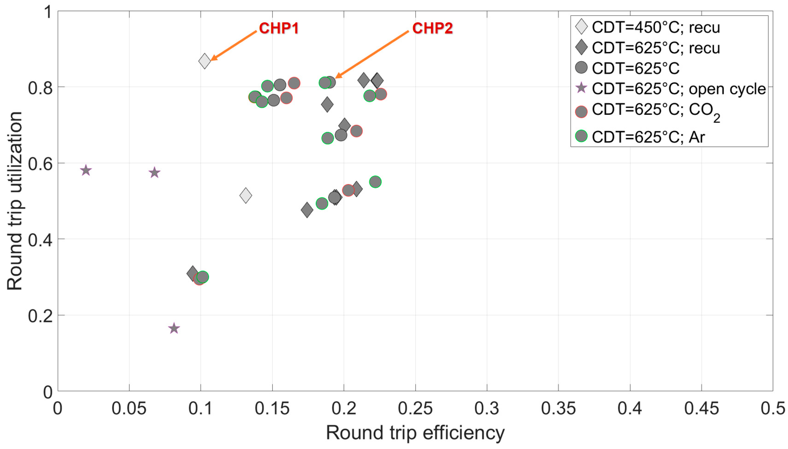
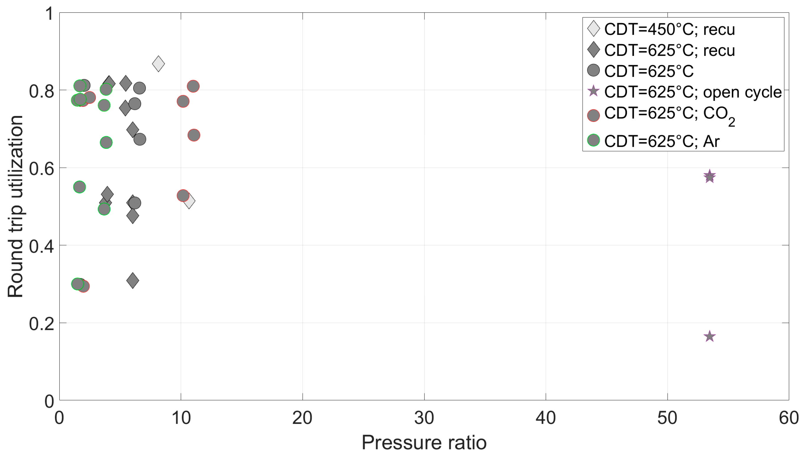
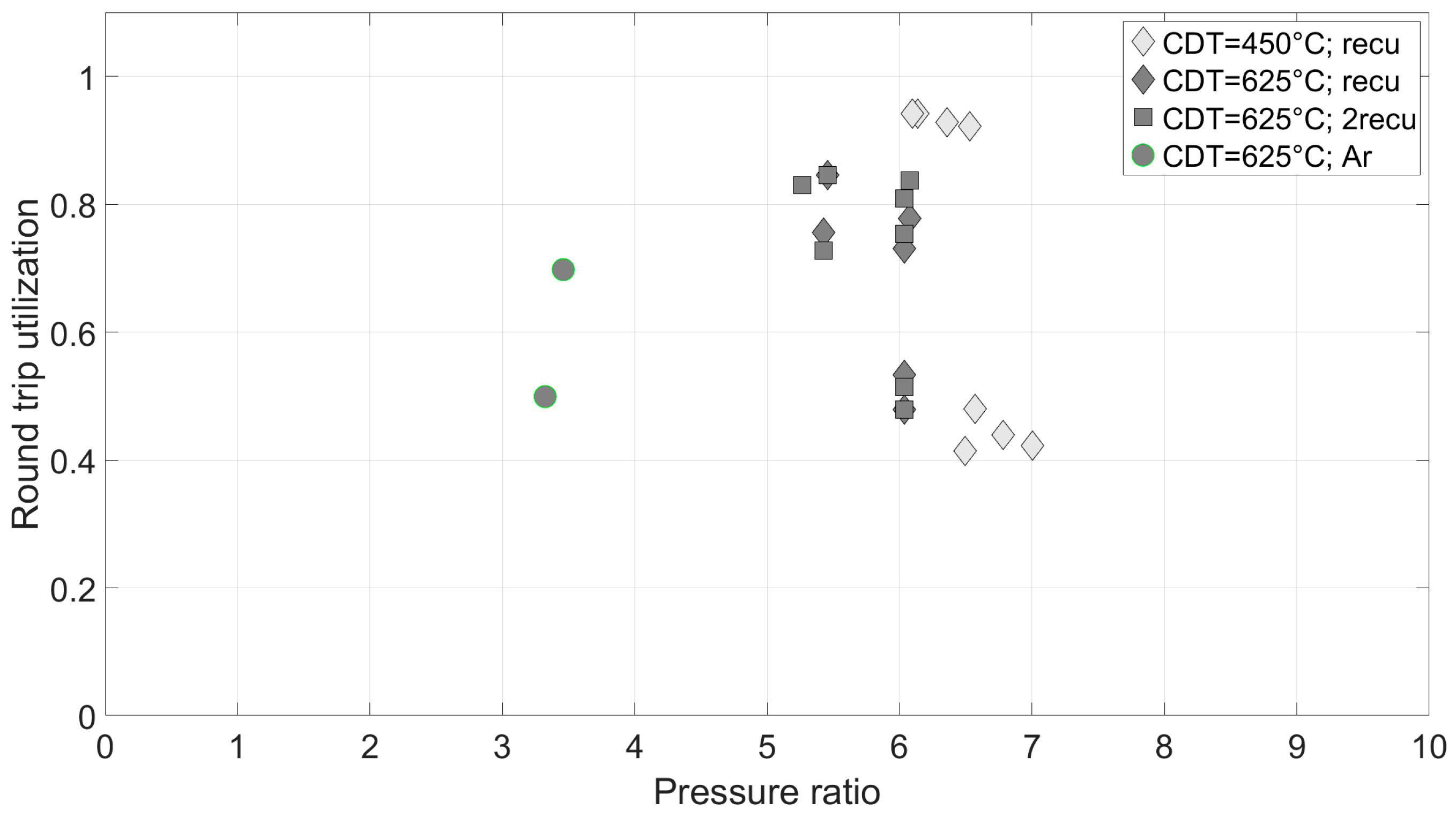
3.2. Coupled Generation of Electricity and Heat with or without Waste Heat Integration

In Figure 10, the round trip utilization (RTU) is plotted against the round trip efficiency (RTE) for the coupled generation of electricity and heat without waste heat integration. Each marker represents a physically feasible concept. Lighter markers represent the lower compressor discharge temperature (CDT) of 450 °C, while darker ones represent a CDT of 625 °C. Red-bordered markers represent concepts using CO2 as the working fluid, while green-bordered ones represent concepts using Argon. Diamonds represent concepts with a recuperator in the charge cycle. The star-shaped markers represent the results for open concepts.
Values for RTU of up to 87% are calculated, albeit at the expense of RTE, which all remain below 25%. Regarding open cycles, it should be noted that only very few concepts are physically feasible, and they show very low values for both RTU and RTE. While the use of different working fluids in the closed concepts also does not show clear trends, the use of a recuperator in the charge cycle allows for concepts with CDT = 450 °C; without a recuperator, concepts with a lower compressor discharge temperature are not feasible.
The following figures depict the results for RTU over the pressure ratio (Π) of the compressor in the charging cycle: Figure 11 covers the full pressure ratio range, while Figure 12 is limited to 0 to 10.
Most concepts have pressure ratios up to 10 and slightly above. The exception is the open concepts, where the required pressures are significantly higher, with achievable values for RTU being low, as mentioned earlier. In closed concepts, it is noticeable that the working fluid argon enables lower pressure ratios.
As lead concepts for coupled generation of electricity and heat without waste heat integration, those defined with the highest RTU for CDT = 450 °C and CDT = 625 °C are chosen, while keeping the systems as simple as possible. If similar RTU values are obtained, the simpler system is selected, as shown in Figure 10:
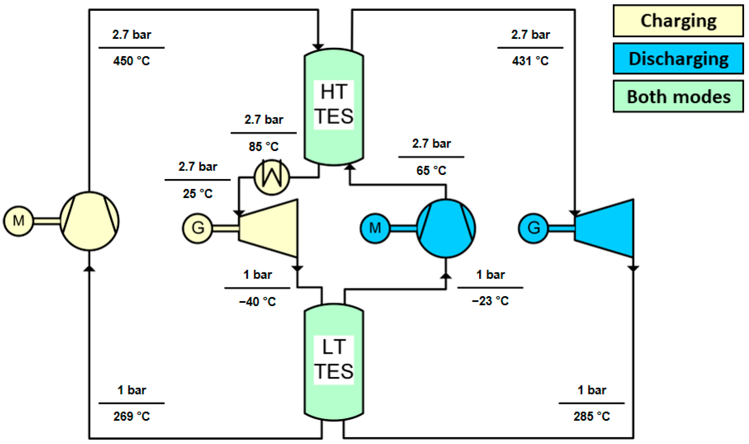
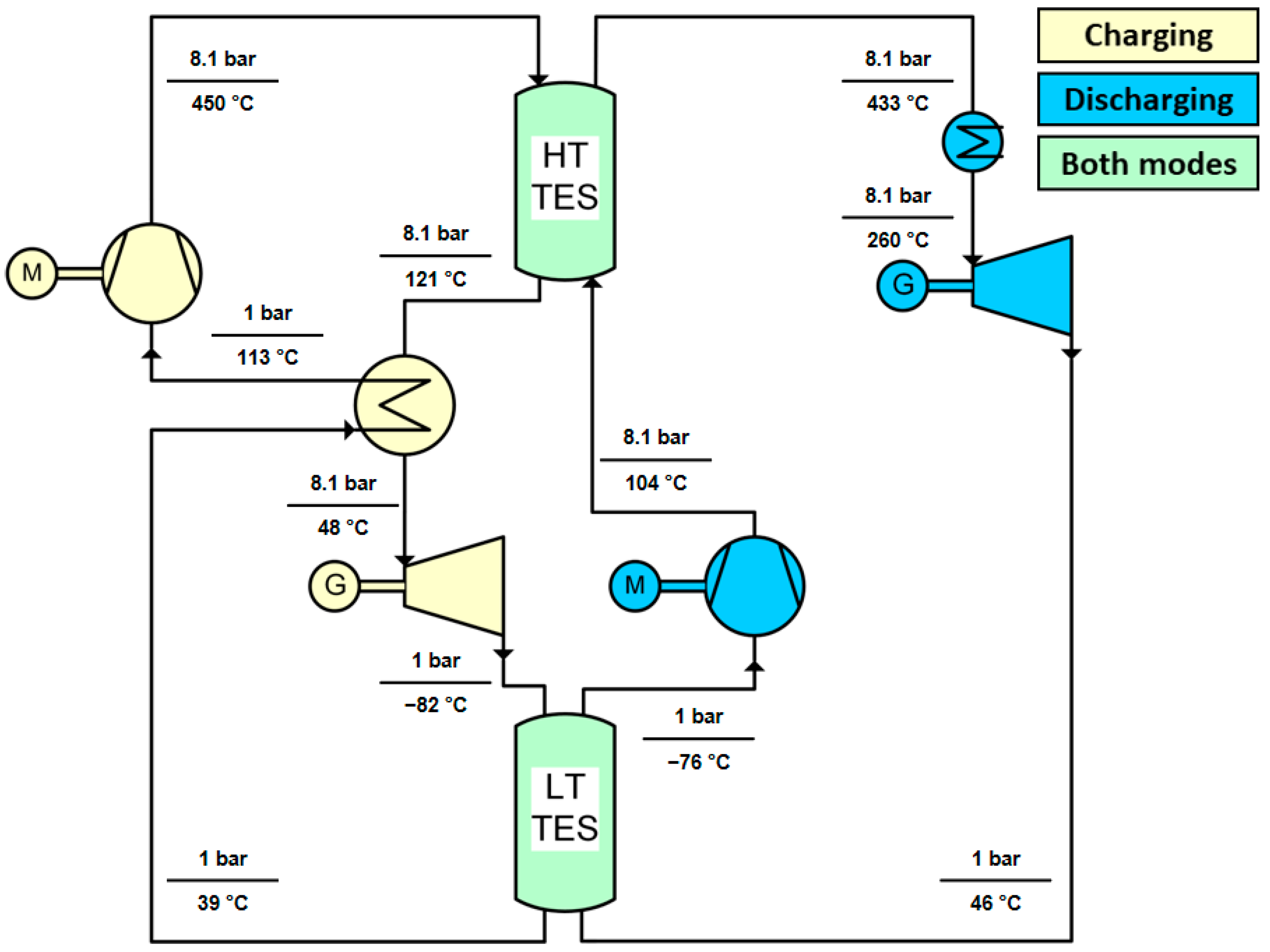
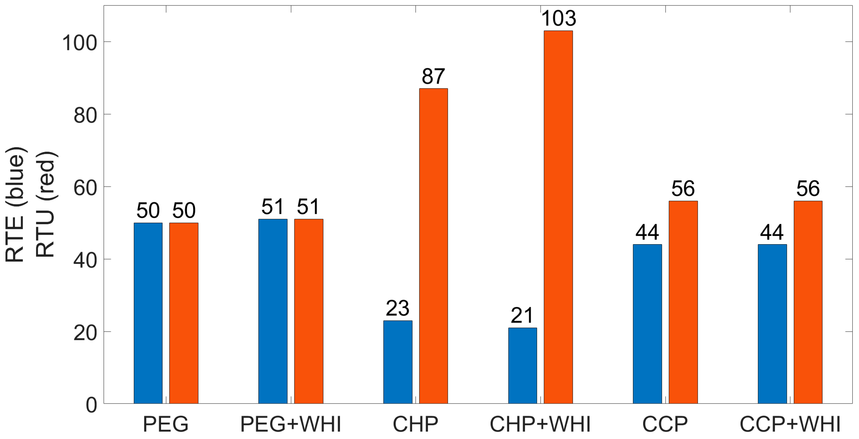
  • CHP1: Working fluid is air. Process heat extraction before the turbine in the discharge line. Recuperator in the charge line. ϑmax = 450 °C; RTU = 86.8%; RTE = 10.3%; Π = 8.1. Flowchart: Figure 13.
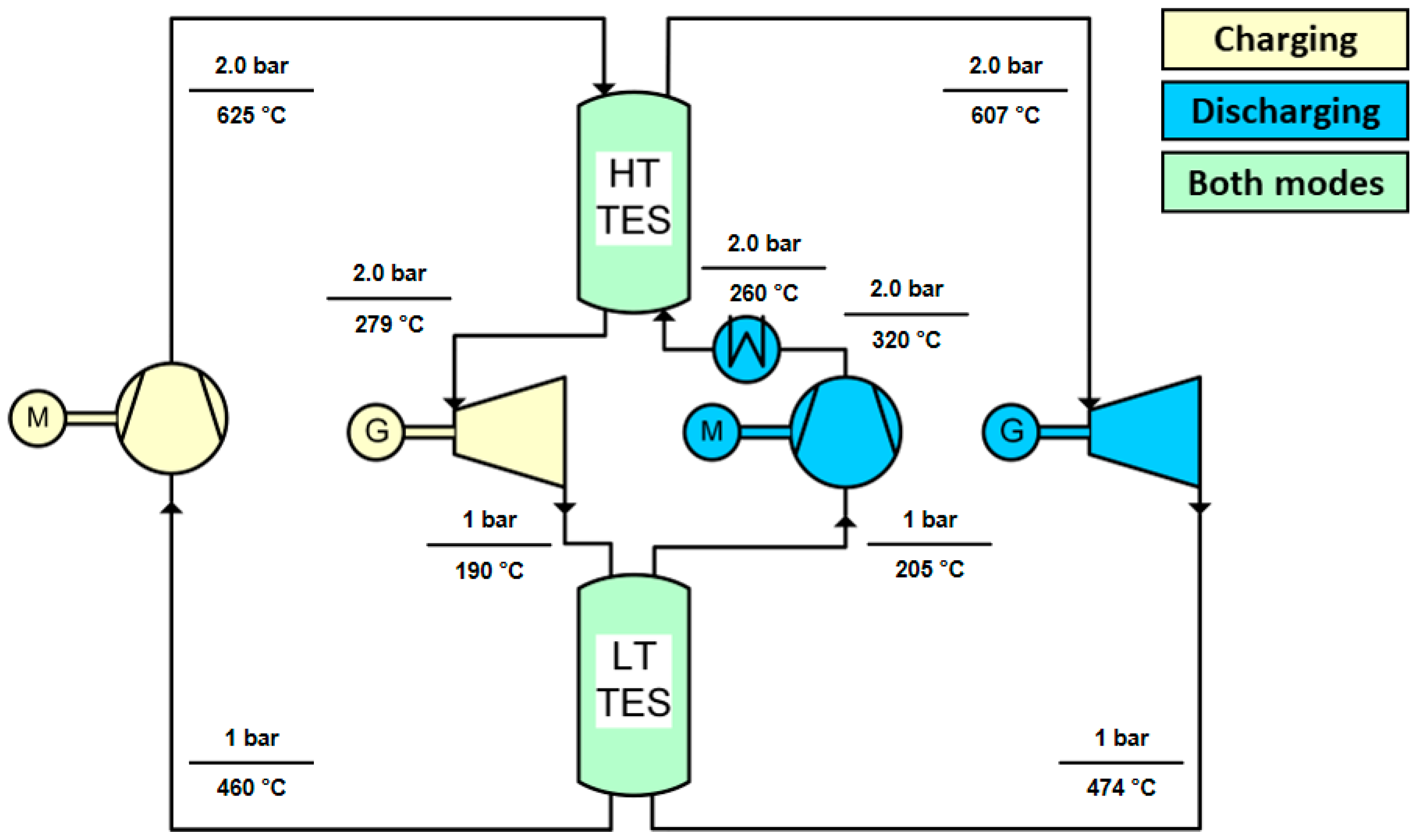
  • CHP2: Working fluid is air. Process heat extraction after the compressor in the discharge line. ϑmax = 625 °C; RTU = 81.2%; RTE = 19.0%; Π = 2.0. Flowchart: Figure 14.
In Figure 15, Figure 16 and Figure 17, the results for concepts with additional waste heat integration are depicted. The square markers represent concepts with a recuperator in both the charge and discharge lines.
The integration of waste heat leads to higher RTU values, reaching nearly above 100%.
As lead concepts for the coupled generation of electricity and heat with waste heat integration, the following are defined, as shown in Figure 15:
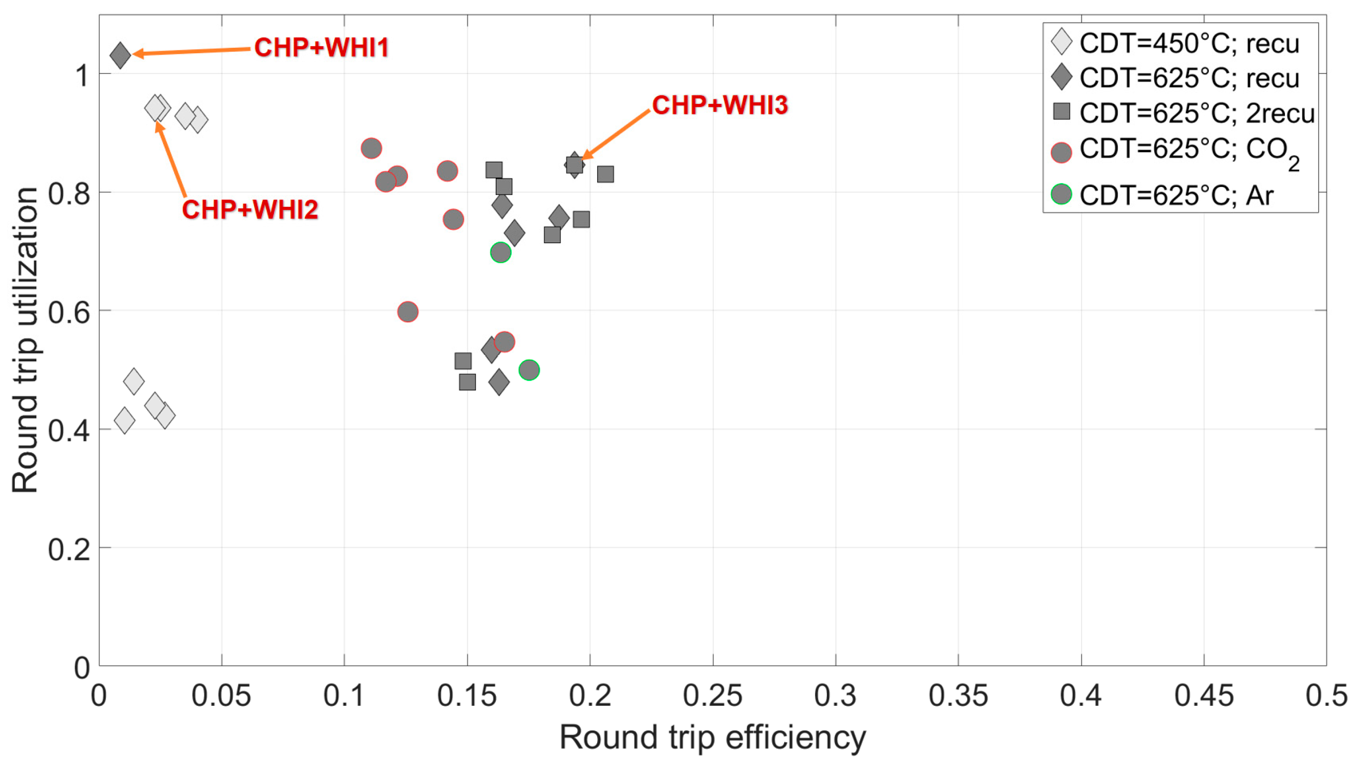
  • CHP+WHI1: Working fluid is air. Process heat extraction before the turbine in the discharge line. Waste heat integration before the turbine in the charge line. Recuperator in the charge line. ϑmax = 625 °C; RTU = 103.1%; RTE = 0.9%; Π = 12.3. Flowchart: Figure 18.
  • CHP+WHI2: Working fluid is air. Process heat extraction before the turbine in the discharge line. Waste heat integration after the low-temperature thermal energy storage (LT-TES) in the charge line. Recuperator in the charge line. ϑmax = 450 °C; RTU = 94.2%; RTE = 2.5%; Π = 6.1. Flowchart: Figure 19.
  • CHP+WHI3: Working fluid is air. Process heat extraction after both the compressor and the turbine in the discharge line. Waste heat integration after the turbine in the charge line. Recuperator in the charge line. ϑmax = 625 °C; RTU = 84.6%; RTE = 19.4%; Π = 5.5. Flowchart: Figure 20.
Three lead concepts were chosen because CHP+WHI1 and CHP+WHI2 yield very high RTU values but very low RTE values. CHP+WHI3 has a high RTU value and still a notable RTE value. However, the system with two points for processing heat extraction is more complex, and the gradients at the recuperator are very small, which could lead to convergence problems in the planned quasi-stationary system simulations.

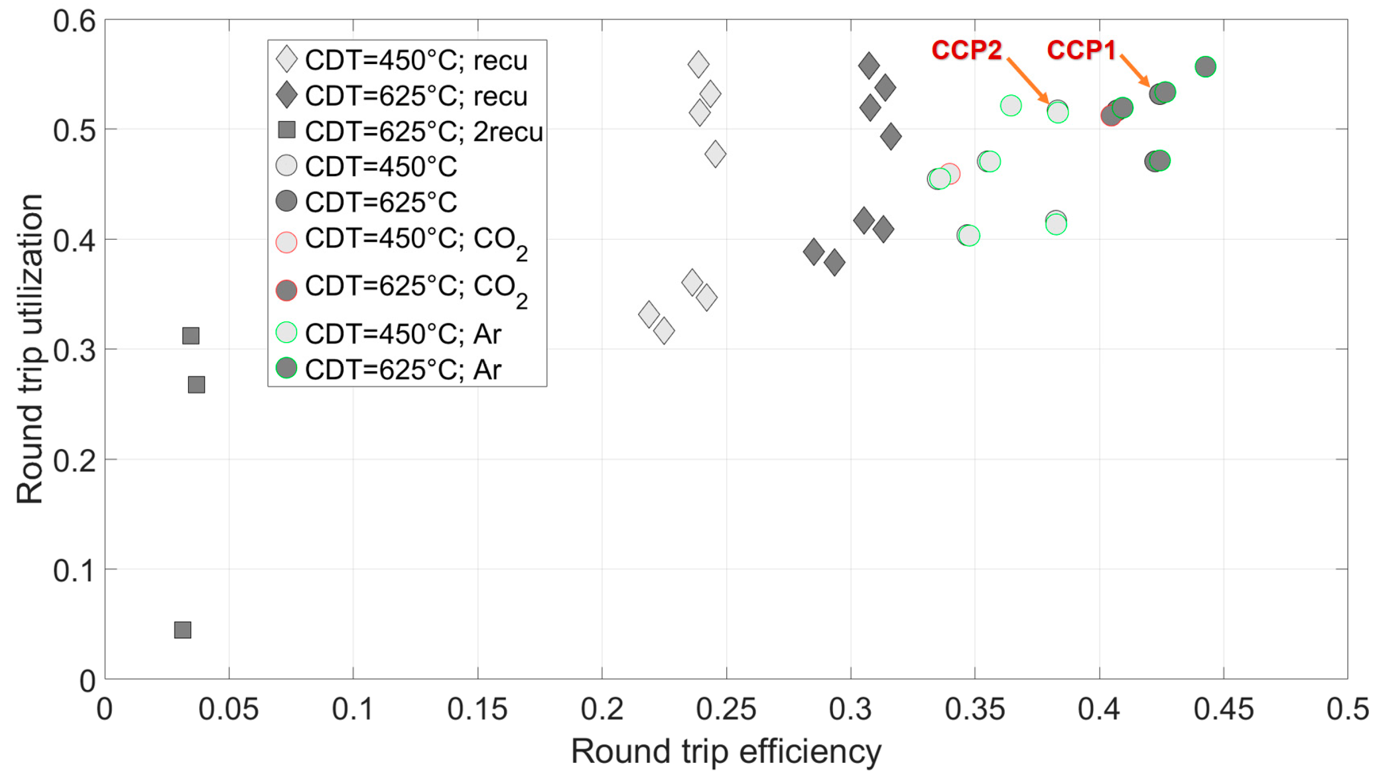
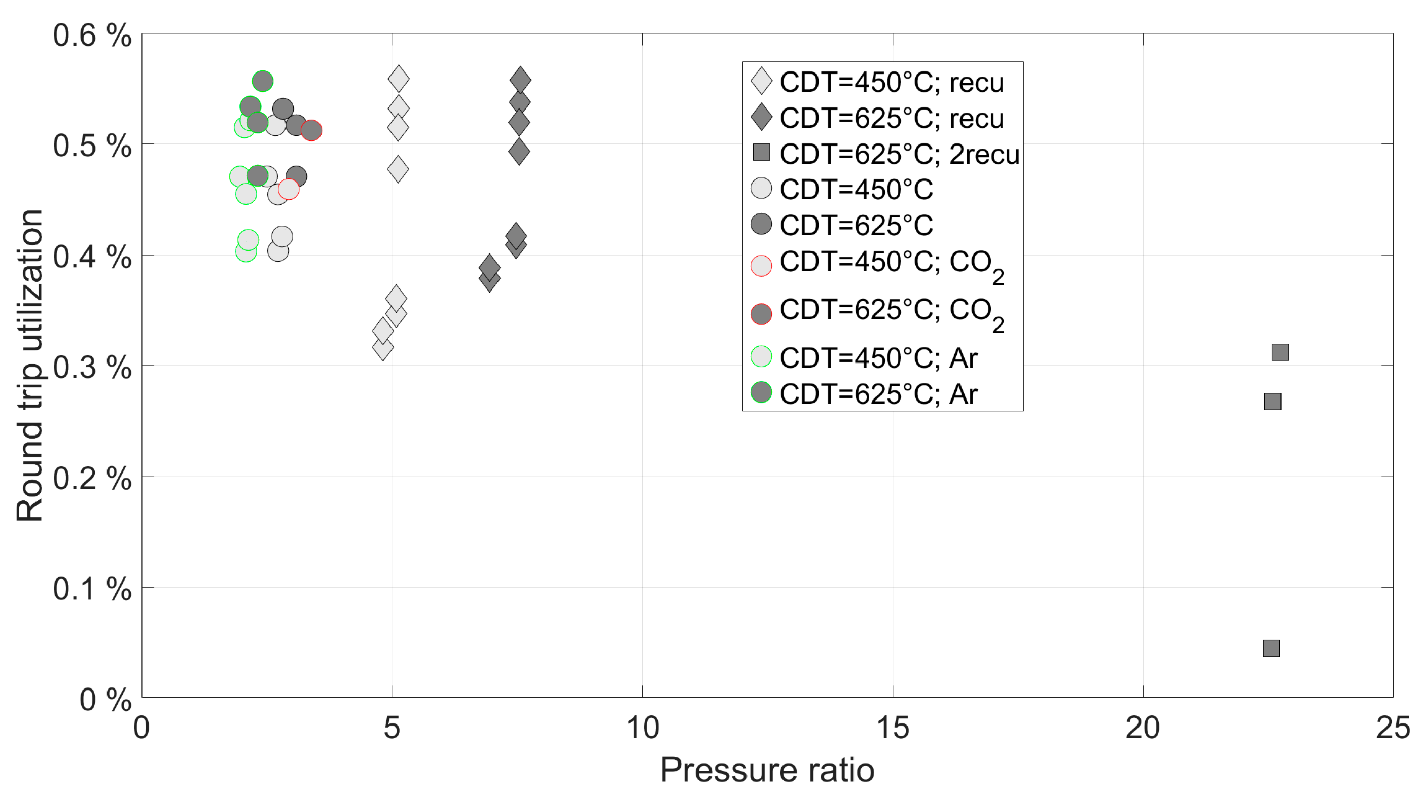
3.3. Coupled Generation of Electricity and Cooling with or without Waste Heat Integration

In Figure 21, the round trip utilization (RTU) is plotted against the round trip efficiency (RTE) for the coupled generation of electricity and cooling without waste heat integration. Each marker represents a physically feasible concept. Lighter markers represent the lower compressor discharge temperature (CDT) of 450 °C, while darker ones represent a CDT of 625 °C. Red-bordered markers represent concepts using CO2 as the working fluid, and green-bordered ones represent concepts using Argon. Diamonds represent concepts with a recuperator in the charging line, while lying squares represent those with an additional recuperator in the discharging line.
The calculated values for RTU range from 30% to 55%, which are lower compared to the coupled generation of electricity and heat, but the RTE ranges from 30% to 45%, which is significantly higher here. The number of solutions with a recuperator in the charging line as well as those with Argon as the working fluid seems to dominate, but there are also few physically feasible concepts based on air and without a recuperator. However, the concepts with two recuperators perform significantly worse than the rest.
In the following diagrams, the results for RTU over the compressor pressure ratio (Π) in the charging line are plotted: Figure 22 covers the full range of compressor pressure ratio, while Figure 23 restricts the range to 0 to 10.
It becomes clear that the dominance mentioned earlier is only apparent as the markers were directly overlapping there. In fact, there are approximately as many solutions for air as the working fluid even without the use of a recuperator. Furthermore, the concepts with a recuperator show significantly higher compressor pressure ratios, but the efficiencies are not higher.
For future detailed investigations, the lead concepts for the coupled generation of power and cooling without heat integration are defined as those with CDT = 450 °C and CDT = 625 °C that exhibit the best combination of high RTU and high RTE, while remaining as simple as possible. In cases where similarly high values for both RTU and RTE are achieved, the simpler system is chosen, see Figure 21:
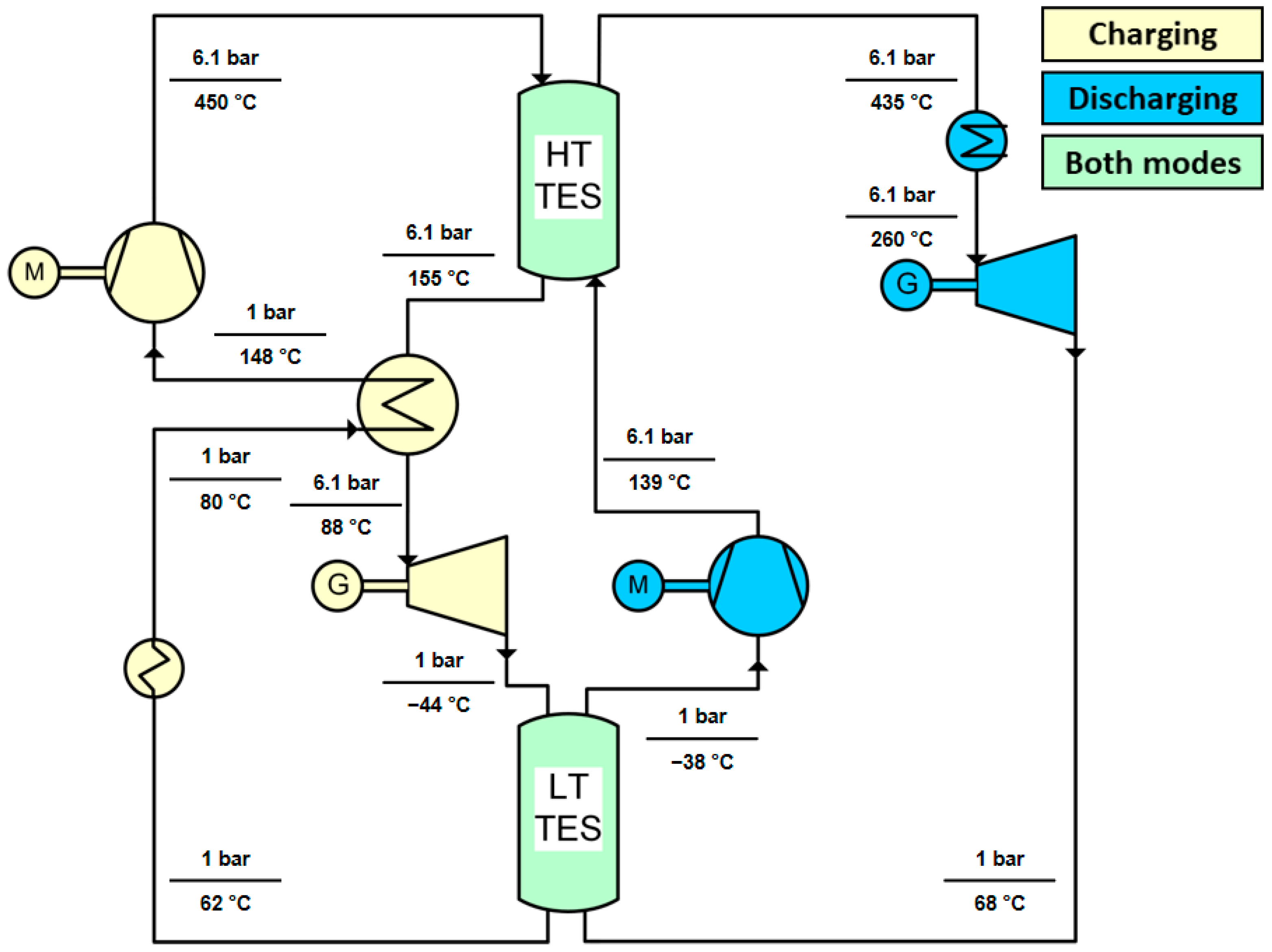
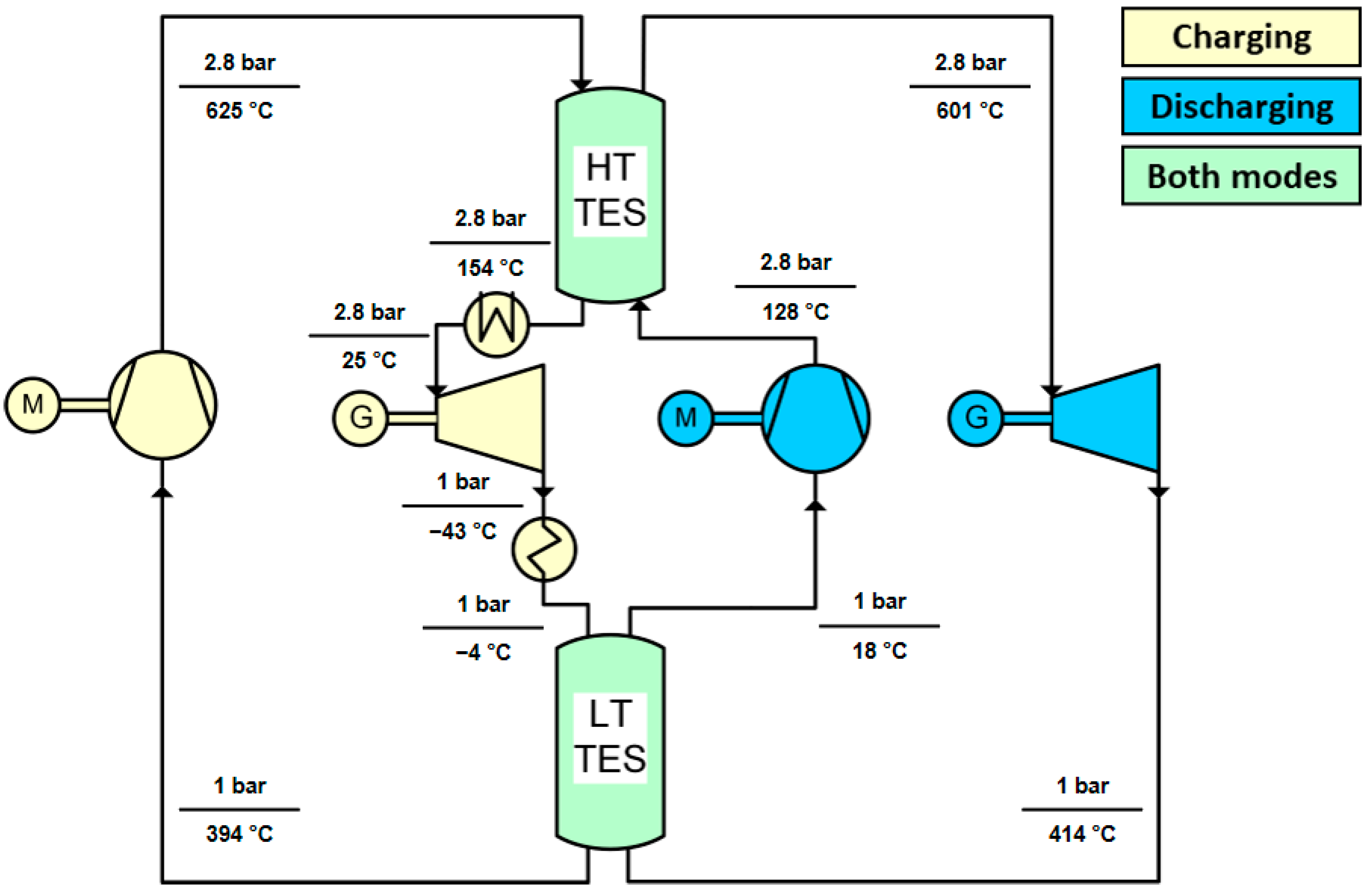
  • CCP1: Working fluid air. Cooler before the turbine in the load path. Cooling provision after the turbine in the load path. Cooler before the compressor in the discharge path. ϑmax = 625 °C; RTU = 53.2%; RTE = 42.4%; Π = 2.8. Flow scheme: Figure 24.
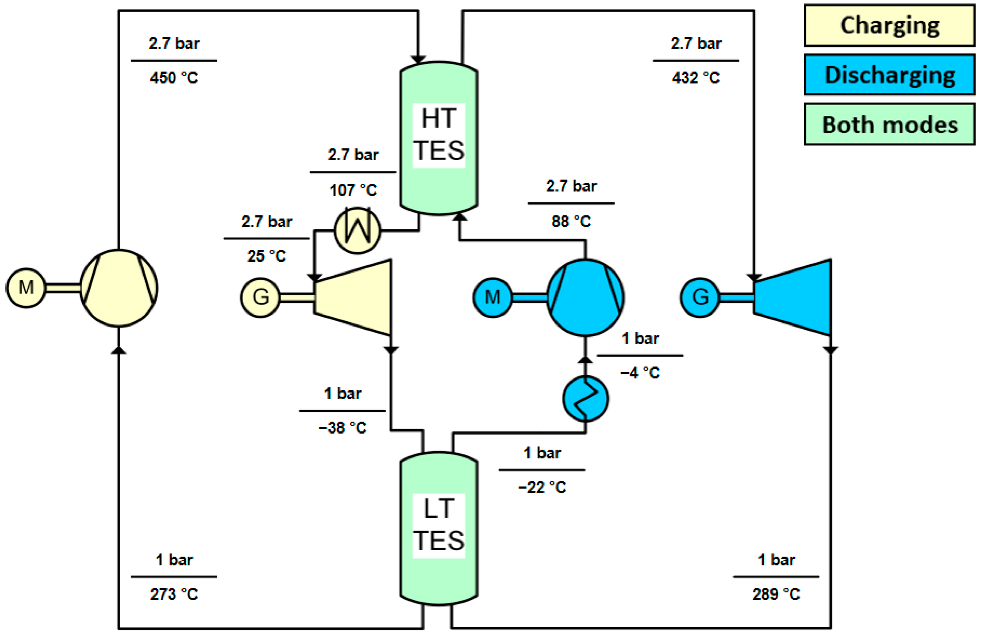
  • CCP2: Working fluid air. Cooler before the turbine in the load path. Cooling provision before the compressor in the discharge path. ϑmax = 450 °C; RTU = 51.7%; RTE = 38.3%; Π = 2.7. Flow scheme: Figure 25.
In Figure 26 and Figure 27, the results for the concepts of coupled electricity and cooling generation under the assumption of waste heat integration are presented.
The additional integration of waste heat leads to more physically possible solutions than without heat input. However, it is also evident that this does not result in significant improvements in terms of the RTU and RTE values. Therefore, it is not meaningful to discuss these results in detail. Accordingly, for future detailed investigations, no concepts with waste heat integration will be selected for the coupled generation of electricity and cooling.

3.4. Coupled Generation of Electricity, Heat, and Cooling

There are no physically possible solutions for the simultaneous coupled generation of electricity, heat, and cooling under the defined conditions. Deviating from the set temperature levels for heat or cooling provision, or allowing for different or variable compressor discharge temperatures, could enable solutions here. However, this was not possible within the scope of the present study and was therefore not investigated.

4. Discussion

In recent years, Carnot battery technology has continued to evolve. Representative research initiatives, which were already known at the beginning of the project, have been further developed. For example, the National Facility for Pumped Heat Energy Storage (Newcastle University, Newcastle upon Tyne, UK), sourced from Isentropic Ltd, a manufacturer based in Fareham, UK, demonstrated a 150 kW system at grid scale [38], the CHESTER project (EU Horizon 2020) developed a 10 kWe prototype system at laboratory scale [39], and the Malta System (Malta, Inc., Cambridge, MA, USA) developed a 100 MW solution at grid scale [40]. Novotny et al. [4] provide an overview of commercial activities. In addition to these prototype and demonstration projects, numerous publications have emerged covering specific system configurations and their individual aspects. However, no systematic concept studies on Carnot batteries in a comparable scope to the present study have been published.
Unfortunately, a comparison to simulation results in the literature cannot be made at this point, as no comparable concepts exist. Firstly, the boundary conditions and assumptions are neither comparable nor identical. Secondly, the topology is different. Additionally, the heat exchangers in the individual concepts discussed in the literature are always located at different positions.

5. Conclusions

This study represents the first comprehensive systematic structural analysis of Brayton batteries. A universal simulation tool was developed in Ebsilon Professional® for this purpose. For a specific set of boundary conditions, a concept study was conducted for various purposes, including pure electricity generation as well as various coupled generation of electricity, heat, and cooling with and without waste heat integration, resulting in the calculation of over 200,000 concepts.
Less than 1% of the calculated concepts lead to physically realizable results. For pure electricity generation, round trip efficiencies range from 20 to 50%. Concepts operating at CDT = 450 °C show lower round trip efficiencies than those operating at CDT = 625 °C. There is no discernible trend for the working fluids, and the same applies to the inclusion or exclusion of recuperators. The inclusion of additional waste heat does not lead to significantly higher values.
Coupled generation of electricity and heat or cooling improves overall efficiency, reflected in increased values for RTU. However, this comes at the expense of RTE. The integration of waste heat leads to increased values for round trip utilization in concepts for heat provision but not in concepts for cooling provision. Concepts operating at CDT = 450 °C show lower RTE values than those with CDT = 625 °C; this does not mean that their RTU values must also be lower. For open concepts, very few solutions were achieved, but these have lower efficiency. No clear trend is observed for the working fluids. The inclusion of a recuperator in the charging line enables the development of concepts for coupled generation of electricity and heat at CDT = 450 °C. There are no physically possible solutions for simultaneous coupled generation of electricity, heat, and cooling. The maximum achievable efficiencies are summarized in Figure 28 for the different applications.
If solutions were available, two to three lead concepts per application purpose were defined. The identified lead concepts are consistently air-operated systems at relatively low pressure (<13 bar), with or without a recuperator in the charging line, and with heat supply or removal at various points in the process, considering CDT values of 450 °C or 625 °C. These lead concepts will be further investigated through dynamic system simulations, including component design, with a focus on thermal energy storage. In addition to dynamic analysis, another focus will be on developing configurations that can generate not only electricity but also heat and cooling, either simultaneously or with a time delay.
As discussed earlier, the lack of comparable simulation results in the literature underscores the unique advantages of the systematic structural analysis presented here. The most efficient concepts can be found for a specific set of parameters, which show significantly better performance values than concepts from the literature that may not represent the best solution for that particular parameter set. This is particularly the case for concepts with coupled generation of electricity and heat or coupled generation of electricity and cooling, as the published research in this area is limited.

Funding

This research was funded by the German Federal Ministry for Economic Affairs and Climate Action, grant number 03EI3045.

Institutional Review Board Statement

Not applicable.

Informed Consent Statement

Not applicable.

Data Availability Statement

The original contributions presented in the study are included in the article, further inquiries can be directed to the corresponding author.

Conflicts of Interest

The author declares no conflicts of interest. The funders had no role in the design of the study; in the collection, analyses, or interpretation of data; in the writing of the manuscript; or in the decision to publish the results.

Abbreviations

CCPCombined Cooling and Power
CDTCompressor Discharge Temperature
CHPCombined Heat and Power
CO2Carbon Dioxide
CSPConcentrated Solar Power
HT-TESHigh-Temperature Thermal Energy Storage
LT-TESLow-Temperature Thermal Energy Storage
ORCOrganic Rankine Cycle
PHESPumped Heat Storage
PTESPumped Thermal Electricity Storage
RTERound Trip Efficiency
RTURound Trip Utilization
SCO2Supercritical Carbon Dioxide
TESThermal Energy Storage
WHIWaste Heat Integration

References

  1. Carnot Batteries. Available online: https://iea-es.org/task-36/ (accessed on 28 June 2024).
  2. Olympios, A.V.; McTigue, J.D.; Farres-Antunez, P.; Tafone, A.; Romagnoli, A.; Li, Y.; Ding, Y.; Steinmann, W.-D.; Wang, L.; Chen, H.; et al. Progress and prospects of thermomechanical energy storage—A critical review. Prog. Energy 2021, 3, 022001. [Google Scholar] [CrossRef]
  3. Dumont, O.; Frate, G.F.; Pillai, A.; Lecompte, S.; De Paepe, M.; Lemort, V. Carnot battery technology: A state-of-the-art review. J. Energy Storage 2020, 32, 101756. [Google Scholar] [CrossRef]
  4. Novotny, V.; Basta, V.; Smola, P.; Spale, J. Review of Carnot Battery Technology Commercial Development. Energies 2022, 15, 647. [Google Scholar] [CrossRef]
  5. Weissenbach, B. Thermischer Kraftspeicher. European Patent EP/0003980 A1, 16 February 1979. [Google Scholar]
  6. Ruer, J. Installation and Methods for Storing and Recovering Electrical Energy. International Patent WO 2008 148962 A2, 11 December 2008. [Google Scholar]
  7. MacNaughten, J.; Howes, J.S. Energy Storage. International Patent WO 2009 044139 A2, 09 April 2009. [Google Scholar]
  8. Smallbone, A.; Jülch, V.; Wardle, R.; Roskilly, A.P. Levelised Cost of Storage for Pumped Heat Energy Storage in comparison with other energy storage technologies. Energy Convers. Manag. 2017, 152, 221–228. [Google Scholar] [CrossRef]
  9. Laughlin, R.B.; Larochelle, P.; Cizek, N. Systems and Methods for Energy Storage and Retrieval. United States Patent US 2015 0260463 A1, 17 September 2015. [Google Scholar]
  10. Laughlin, R.B. Adiabatic Salt Energy Storage. United States Patent US 2016 0298455 A1, 13 October 2016. [Google Scholar]
  11. McTigue, J.D.; Farres-Antunez, P.; Ellingwood, K.; Neises, T.; White, A.J. Pumped Thermal Electricity Storage with Supercritical CO2 Cycles and Solar Heat Input; SolarPACES: Daegu, Republic of Korea, 2019. [Google Scholar]
  12. The GridScale Technology Explained|Stiesdal. Available online: https://www.stiesdal.com/storage/the-gridscale-technology-explained/ (accessed on 2 May 2024).
  13. Schneider, G.; Maier, H.; Häcker, J.; Siegele, S. Electricity Storage with a Solid Bed High Temperature Thermal Energy Storage System (HTTES)—A Methodical Approach to Improve the Pumped Thermal Grid Storage Concept. Atlantis Highlights Eng. 2021, 6, 26–33. [Google Scholar]
  14. White, A.; Parks, G.; Markides, C.N. Thermodynamic analysis of pumped thermal electricity storage. Appl. Therm. Eng. 2013, 53, 291–298. [Google Scholar] [CrossRef]
  15. Laughlin, R.B. Pumped thermal grid storage with heat exchange. J. Renew. Sustain. Energy 2017, 9, 044103. [Google Scholar] [CrossRef]
  16. Kim, Y.-M.; Shin, D.-G.; Lee, S.-Y.; Favrat, D. Isothermal transcritical CO2 cycles with TES (thermal energy storage) for electricity storage. Energy 2013, 49, 484–501. [Google Scholar] [CrossRef]
  17. Thess, A. Thermodynamic Efficiency of Pumped Heat Electricity Storage. Phys. Rev. Lett. 2013, 111, 110602. [Google Scholar] [CrossRef] [PubMed]
  18. Guo, J.; Cai, L.; Chen, J.; Zhou, Y. Performance optimization and comparison of pumped thermal and pumped cryogenic electricity storage systems. Energy 2016, 106, 260–269. [Google Scholar] [CrossRef]
  19. Bortolotti, M. EASE/EERA European Energy Storage Technology Development Roadmap. 2017. Available online: https://www.eera-set.eu/component/attachments/?task=download&id=312 (accessed on 2 May 2024).
  20. Knödler, P. Thermo-Mechanical Investigations of Packed Beds for High Temperature Heat Storage: Continuum Modeling. Appl. Sci. 2019, 9, 2569. [Google Scholar] [CrossRef]
  21. McTigue, J.D.; Markides, C.N.; White, A.J. Performance response of packed-bed thermal storage to cycle duration perturbations. J. Energy Storage 2018, 19, 379–392. [Google Scholar] [CrossRef]
  22. Bruch, A.; Fourmigué, J.F.; Couturier, R. Experimental and numerical investigation of a pilot-scale thermal oil packed bed thermal storage system for CSP power plant. Solar Energy 2014, 105, 116–125. [Google Scholar] [CrossRef]
  23. Zunft, S.; Krüger, M.; Dreißigacker, V.; Belik, S.; Hahn, J.; Knödler, P. ADELE-ING: Engineering-Vorhaben für die Errichtung der ersten Demonstrationsanlage zur Adiabaten Druckluftspeichertechnik; Öffentlicher Schlussbericht; Deutsches Zentrum für Luft- und Raumfahrt e.V.: Stuttgart, Germany, 2017. [Google Scholar]
  24. McTigue, J. Analysis and Optimisation of Thermal Energy Storage. Ph.D. Thesis, University of Cambridge, Cambridge, UK, 2016. [Google Scholar]
  25. Zunft, S.; Krüger, M.; Dreißigacker, V.; Mayer, P.-M.; Niklasch, C.; Bertsch, C. Adiabate Druckluftspeicher für die Elektrizitätsversorgung—Der ADELE-Wärmespeicher. In Kraftwerkstechnik; TK Verlag: Dresden, Germany, 2012; Volume 4, pp. 749–757. [Google Scholar]
  26. Bonk, A.; Braun, M.; Sötz, V.; Bauer, T. Solar Salt—Pushing an old material for energy storage to a new limit. Appl. Energy 2020, 262, 114535. [Google Scholar] [CrossRef]
  27. Farres-Antunez, P.; Xue, H.; White, A.J. Thermodynamic analysis and optimisation of a combined liquid air and pumped thermal energy storage cycle. J. Energy Storage 2018, 18, 90–102. [Google Scholar] [CrossRef]
  28. Benato, A. Performance and cost evaluation of an innovative Pumped Thermal Electricity Storage power system. Energy 2017, 138, 419–436. [Google Scholar] [CrossRef]
  29. Benato, A.; Stoppato, A. Heat transfer fluid and material selection for an innovative Pumped Thermal Electricity Storage system. Energy 2018, 147, 155–168. [Google Scholar] [CrossRef]
  30. Chen, L.X.; Hu, P.; Zhao, P.P.; Xie, M.N.; Wang, F.X. Thermodynamic analysis of a High Temperature Pumped Thermal Electricity Storage (HT-PTES) integrated with a parallel organic Rankine cycle (ORC). Energy Convers. Manag. 2018, 177, 150–160. [Google Scholar] [CrossRef]
  31. Wettstein, H.E. The Potential of GT Combined Cycles for Ultra High Efficiency. In Proceedings of the ASME Turbo Expo 2012, Copenhagen, Denmark, 11–15 June 2012. [Google Scholar]
  32. Seydel, C.G. Thermodynamische Auslegung und Potentialstudien von Heavy-Duty Gasturbinen für kombinierte Gas- und Dampfkraftwerke. Ph.D. Thesis, Ruhr-Universität Bochum, Bochum, Germany, 2014. [Google Scholar]
  33. Zehner, P. Vier-Quadranten-Charakteristiken Mehrstufiger Axialer Turbinen; VDI-Verlag GmbH: Düsseldorf, Germany, 1980. [Google Scholar]
  34. Agorameter. Available online: https://www.agora-energiewende.de/daten-tools/agorameter/chart/today/power_generation/29.01.2024/01.02.2024/hourly (accessed on 2 May 2024).
  35. Sterner, M.; Stadler, I. Energiespeicher—Bedarf, Technologien, Integration; Springer Vieweg: Berlin/Heidelberg, Germany, 2017. [Google Scholar]
  36. Krystallas, P.-A. Technische, organisatorische und ökonomische Analyse der Fernkälte am Projekt Fernkälte München. Ph.D. Thesis, Technische Universität München, Munich, Germany, 2018. [Google Scholar]
  37. Eifler, W.; Schlücker, E.; Spicher, U.; Will, G. Küttner—Kolbenmaschinen; Vieweg+Teubner: Wiesbaden, Germany, 2009. [Google Scholar]
  38. Ameen, M.T.; Ma, Z.; Smallbone, A.; Norman, R.; Roskilly, A.P. Demonstration system of pumped heat energy storage (PHES) and its round-trip efficiency. Appl. Energy 2023, 333, 120580. [Google Scholar] [CrossRef]
  39. Theologou, K.; Johnson, M.; Tombrink, J.; Ciganda, J.L.C.; Trebilcock, F.T.; Couvreur, K.; Tassenoy, R.; Lecompte, S. CHESTER: Experimental prototype of a pumped thermal energy storage and management system with thermal integration. Energy Convers. Manag. 2024, 311, 118519. [Google Scholar]
  40. Malta: Our Solution. Available online: https://www.maltainc.com/solution/ (accessed on 2 May 2024).
Figure 1. (a) Flow sheet of a Brayton battery; (b) associated T-s diagram.
Applsci 14 06073 g001
Figure 2. Efficiency definitions.
Applsci 14 06073 g002
Figure 3. Simulation tool in Ebsilon Professional.
Applsci 14 06073 g003
Figure 4. Pure electricity generation without waste heat integration: RTE over Π (complete solution area).
Applsci 14 06073 g004
Figure 5. Pure electricity generation without waste heat integration: RTE over Π (restricted solution area).
Applsci 14 06073 g005
Figure 6. Lead concept PEG1 for pure electricity generation without waste heat integration.
Applsci 14 06073 g006
Figure 7. Lead concept PEG2 for pure electricity generation without waste heat integration.
Applsci 14 06073 g007
Figure 8. Pure electricity generation with waste heat integration: RTE over Π (complete solution area).
Applsci 14 06073 g008
Figure 9. Pure electricity generation with waste heat integration: RTE over Π (restricted solution area).
Applsci 14 06073 g009
Figure 10. Coupled generation of electricity and heat without waste heat integration: RTU over RTE.
Applsci 14 06073 g010
Figure 11. Coupled generation of electricity and heat without waste heat integration: RTU over Π (complete solution area).
Applsci 14 06073 g011
Figure 12. Coupled generation of electricity and heat without waste heat integration: RTU over Π (restricted solution area).
Applsci 14 06073 g012
Figure 13. Lead concept CHP1 for coupled generation of electricity and heat without waste heat integration.
Applsci 14 06073 g013
Figure 14. Lead concept CHP2 for coupled generation of electricity and heat without waste heat integration.
Applsci 14 06073 g014
Figure 15. Coupled generation of electricity and heat with waste heat integration: RTU over RTE.
Applsci 14 06073 g015
Figure 16. Coupled generation of electricity and heat with waste heat integration: RTU over Π (complete solution area).
Applsci 14 06073 g016
Figure 17. Coupled generation of electricity and heat with waste heat integration: RTU over Π (restricted solution area).
Applsci 14 06073 g017
Figure 18. Lead concept CHP+WHI1 for coupled generation of electricity and heat with waste heat integration.
Applsci 14 06073 g018
Figure 19. Lead concept CHP+WHI2 for coupled generation of electricity and heat with waste heat integration.
Applsci 14 06073 g019
Figure 20. Lead concept CHP+WHI3 for coupled generation of electricity and heat with waste heat integration.
Applsci 14 06073 g020
Figure 21. Coupled generation of electricity and cooling without waste heat integration: RTU over RTE.
Applsci 14 06073 g021
Figure 22. Coupled generation of electricity and cooling without waste heat integration: RTU over Π (complete solution area).
Applsci 14 06073 g022
Figure 23. Coupled generation of electricity and cooling without waste heat integration: RTU over Π (restricted solution area).
Applsci 14 06073 g023
Figure 24. Lead concept CCP1 for coupled generation of electricity and cooling without waste heat integration.
Applsci 14 06073 g024
Figure 25. Lead concept CCP2 for coupled generation of electricity and cooling without waste heat integration.
Applsci 14 06073 g025
Figure 26. Coupled generation of electricity and cooling with waste heat integration: RTU over RTE.
Applsci 14 06073 g026
Figure 27. Coupled generation of electricity and cooling with waste heat integration: RTU over Π.
Applsci 14 06073 g027
Figure 28. Summary of results: maximum values for RTE and RTU.
Applsci 14 06073 g028
Table 1. System requirements (summer half-year).
Input/ConsumptionOutput/Supply
ElectricityDuration: 8 h
Daytime restrictions: 8–16 h
Duration: 16 h
Daytime restrictions: 16–8 h
HeatWaste heat
Duration: 24 h
Time of day restrictions: none
Temperature level: 90 °C
Process heat
Duration: 24 h
Time of day restrictions: none
Temperature level: 250 °C
Cold Air conditioning
Duration: 12 h
Daytime restrictions: 8–20 h
Temperature level: 6 °C (Supply)→ 16 °C (Return)
Table 2. System requirements (winter half-year).
Input/IntegrationOutput/Delivery
ElectricityDuration: 8 h
Daytime restrictions: 22–6 h
Duration: 16 h
Daytime restrictions: 6–22 h
HeatWaste heat
Duration: 24 h
Time of day restrictions: none
Temperature level: 90 °C
Process heat
Duration: 24 h
Time of day restrictions: none
Temperature level: 250 °C
Table 3. Concept matrix.
Title 1Closed CycleOpen CycleWith RecuperatorWorking Fluid
Pure electricity generation
(PEG)
X X *Air
X XX *Air
X Air
X Air
X CO2
X Argon
Pure electricity generation with waste heat integration
(PEG+WHI)
X XAir
X XXAir
X Air
X Air
X CO2
X Argon
Coupled generation of electricity and heat
(CHP)
X XAir
X XXAir
X Air
X Air
X CO2
X Argon
Coupled generation of electricity and heat with waste heat integration
(CHP+WHI)
X XAir
X XXAir
X Air
X Air
X CO2
X Argon
Coupled generation of electricity and cooling
(CCP)
X XAir
X XXAir
X Air
X Air
X CO2
X Argon
Coupled generation of electricity and cooling with waste heat integration
(CCP+WHI)
X XAir
X XXAir
X Air
X Air
X CO2
X Argon
Coupled generation of electricity, heat, and cooling
(CHPC)
X XAir
X XXAir
X Air
X Air
X CO2
X Argon
* X stands for recuperator only in the charge line, and XX for recuperator in both the charge and discharge line.
Disclaimer/Publisher’s Note: The statements, opinions and data contained in all publications are solely those of the individual author(s) and contributor(s) and not of MDPI and/or the editor(s). MDPI and/or the editor(s) disclaim responsibility for any injury to people or property resulting from any ideas, methods, instructions or products referred to in the content.

