2. Multi-Material Material Extrusion and Mechanisms of Adhesion
Material extrusion (MEX, also referred to as Fused Layer Modeling or Fused Deposition Modeling) is an additive manufacturing process that uses line-by-line and layer-by-layer application of liquefied thermoplastic polymer in order to build complex parts. In multi-material MEX, the material interface can show almost any geometry and is not restricted to layer boundaries. By utilizing material-specific functions, this switch in material can help to increase the range of functions or integrate functions into fewer parts. In this way, mechanical [
1,
2,
3,
4,
5,
6,
7,
8,
9], electrical or sensory [
10,
11,
12,
13,
14,
15,
16,
17,
18,
19,
20,
21,
22,
23], and magnetic [
24,
25] functions can been implemented, for example.
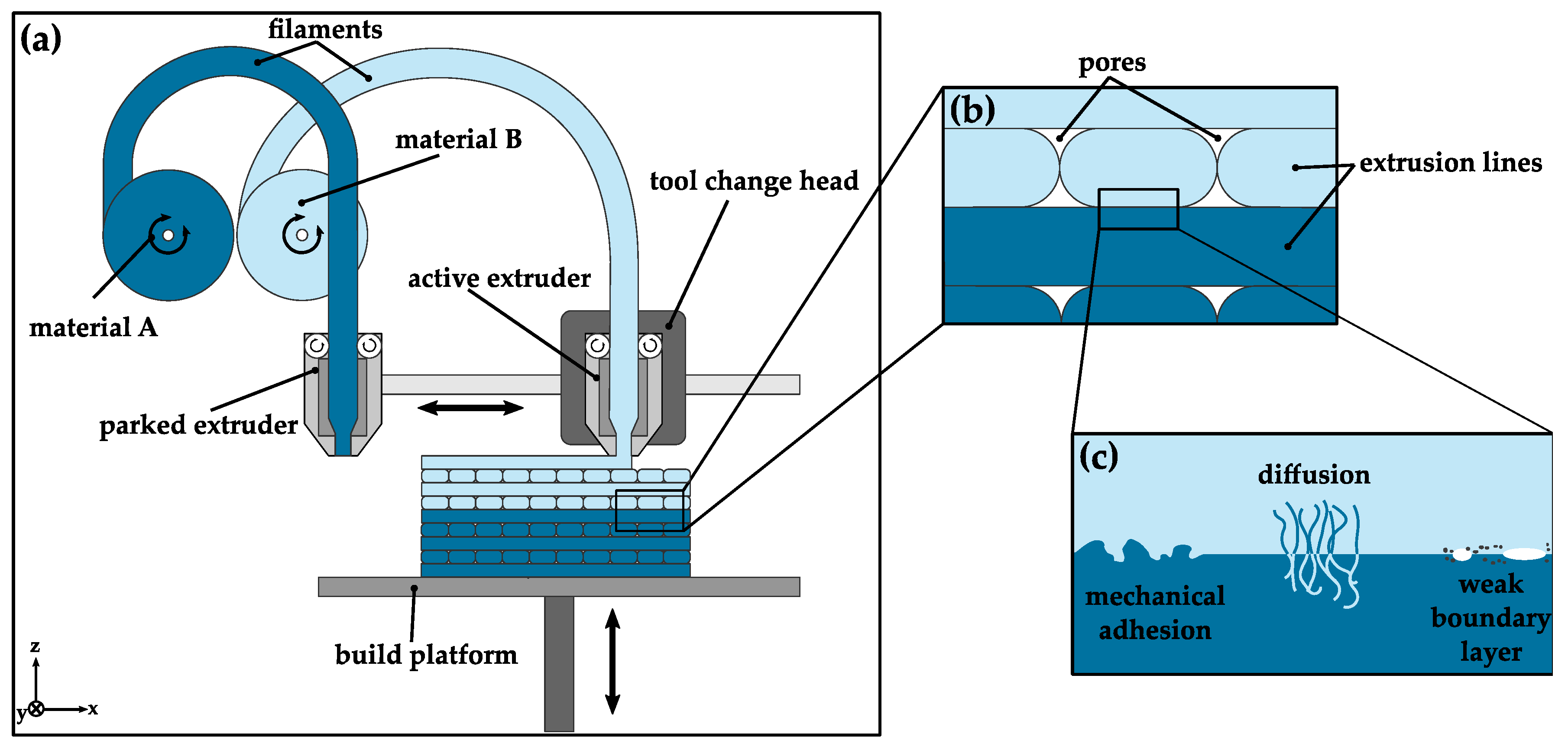
Figure 1 schematically depicts the concept of a multi-material MEX machine as well as the fundamental adhesion principles at play in a multi-material print. In order to produce multi-material components, a MEX machine either needs a mechanism that switches between several extruder units, or a purging step is required while switching materials on a single extruder. While the former is prone to deviations in nozzle position from the mechanical switching process, the latter might lead to contamination at the interface zone due to material residue inside the extruder, which, in turn, might affect adhesion at the interface. As both options might negatively affect the interface strength of the produced component, the switching process requires special attention to ensure optimal mechanical properties.
The final properties of the AM components only form during manufacturing. Hence, the process parameters are significant in producing high strength components, especially when considering multi-material parts. Since a multitude of process parameters might affect the interface strength of multi-material components, a complete overview of all influences is impossible in the scope of this publication. Thus, this paper focuses on extrusion temperature, build plate/chamber temperature, and over/under-extrusion as influences on composite strength. The aim is to determine the degree of variance that can be expected from using suboptimal process parameters in a simple multi-material part, in order to give suggestions for good component or printer design with regard to multi-material manufacturing.
Regarding the possible adhesion mechanisms for polymer–polymer interfaces, only a handful of influences are apparent. On the one hand, temperature is the driving force for several mechanisms of adhesion. Inter-diffusion can only occur due to the movement of the polymer molecules at elevated temperatures. Hence, extrusion temperature and build plate/chamber temperature are expected to influence diffusion at the material interface. In addition, the viscosity of most polymers decreases at higher temperatures, which can affect the filling of microscopic pores at the interface, thereby affecting mechanical adhesion. However, as extrusion temperatures approach the decomposition temperature of the used polymer, impurities at the interface increase, increasing the chance of failure as described by the weak boundary layer theory [
27].
On the other hand, the proper amount of extrusion is crucial to ensure complete overlap of the two materials. Slight over-extrusion of the second material at the interface is expected to promote mechanical adhesion, as the molten polymer is more strongly pressed into the microscopic pores at the interface [
27]. The extrusion amount can be controlled via two mechanisms—either by adjusting the extrusion multiplier in the slicing software in order to change the amount of extruder steps calculated by the software, or by fine-tuning the nozzle distance in the first layer after a tool change to change the volume constrained by the moving nozzle. Reducing the nozzle distance by 5% of the layer height, for example, has the same effect as increasing the extrusion multiplier in the slicing software to (100.0%/95.0%) = 105.3%. However, the nozzle distance is necessarily subject to fluctuations due to the mechanical tool switching mechanism of most printers.
While the relevant literature includes several investigations regarding the influence of extrusion temperature or other process parameters on interface strength, the influence of nozzle distance, especially with regard to fluctuations due to tool switching, is commonly neglected. Ermolai et al. examined the lap shear strength of multi-material combinations depending on extrusion width, line direction, line overlap, and print speed using an Ultimaker 3 printer with a nozzle-switching mechanism but did not take the variance of the switching mechanism into account [
28]. Similarly, Rabbi et al. conducted peel tests of PLA–Nylon specimens fabricated with an Ultimaker 3 without considering the nozzle height fluctuations [
29,
30]. Delia et al. investigated the lap shear strength of the PMMA–PC material combination fabricated with an E3D toolchanger without taking the precision of the tool-switching mechanism into account [
31]. Similarly, Goh et al. conducted tests on the tensile interface strength of TPU and conductive PLA fabricated with an E3D toolchanger, giving no thought to the switching mechanism [
32]. Freund et al. used an X400 by German RepRap GmbH to fabricate roll peel specimens of a variety of material combinations without taking the precision of the leveling of both nozzles into consideration [
33]. Baca et al. described the challenges of maintaining leveling of each nozzle in a self-developed multi-nozzle head, even without an active switching mechanism [
34] and consequently improved their setup by including capacitive sensors in a subsequent publication [
35]. However, the publication was unclear on the exact deviations in offset between each nozzle and how they might have affected adhesion.
Since the fluctuations in the nozzle-switching mechanism should only pose a problem in horizontal interfaces with a multi-nozzle or multi-tool setup, publications investigating the strength of vertical multi-material interfaces [
36,
37], as well as printer setups utilizing a single nozzle for multi-material AM, do not have the same problems, as no tool switching occurs and fluctuations are limited to the motion system. While single-nozzle machines might cause other problems like contamination due to insufficient replacement of the materials during material changes, they are not part of this investigation.
In order to determine the effect of nozzle placement on adhesion, this publication tried to determine the extent of fluctuations for two common printers—an Ultimaker 3 and an E3D toolchanger. The latter was enhanced by a mechanism that could reliably determine nozzle distance and compensate fluctuations in order to investigate the influence of nozzle height fluctuations on interface strength. This mechanism was subsequently used to adjust the extrusion amount in the very first layer after tool changes and determine its effect on interface strength.
Another aim was the investigation of the effect of extrusion temperature and build chamber temperature on multi-material adhesion. Between the mechanisms of diffusion shown in
Figure 1, diffusion is most related to temperature as it is the driving factor. One way of determining diffusion rate is described by the Arrhenius equation as follows [
38]:
with
D: coefficient of diffusion
D0: pre-exponential factor
Ea: activation energy of diffusion
R: gas constant
T: temperature
This equation can be used to compare diffusion rates at different temperatures for the same materials, by comparing the same material at two different temperatures. This results in the following equation that eliminates the pre-exponential factor:
In this way, the effect of a change in temperature can be estimated, with only the activation energy of the diffusion process. Research in the field of thin film welding of PLA has shown the activation energy of self-diffusion of PLA to be 74.8 kJ/mol [
39]. This number only applies to diffusion at PLA–PLA interfaces and not the inter-diffusion at the ABS–PLA interface, as in the case at hand. While the exact activation energy for inter-diffusion is unknown to the authors, a rough estimate shall suffice for the purposes of assessing the influence of build chamber temperature or build plate temperature in the material extrusion process. Other polymers like Poly(ethylene terephthalate) [
40] or Polystyrene [
41] show activation energies of more than 100 kJ/mol even for small molecules with a molecular weight of around 100 g/mol. PLA typically shows a molecular weight of about 10,000 g/mol or more and should thus have a significantly higher activation energy for diffusion in ABS. The activation energy of diffusion typically is not constant over all temperatures, especially when crossing the glass transition temperature. Nonetheless, in order to give an absolute upper boundary of the influence of diffusion, this paper will assume the activation energy of diffusion of PLA in ABS to be a constant 100 kJ/mol. It is clear that this number is significantly lower than the actual activation energy of diffusion. This means that all calculations should be off by a significant margin. However, this way, the influence of temperature will only ever be estimated to be higher than it really is. Hence, if this publication can show the influence of build chamber temperature on diffusion to be negligible through this kind of estimation, it can only ever be even less significant in the real world.
3. Specimen Manufacturing and Experimental Setup
This section describes the setup of the 3D printer and the specimen geometry used. In order to estimate the influence of build chamber temperature, thermal imaging was conducted during printing and is also as described.
3.1. Thermographic Imaging
In order to estimate the cooling behavior of PLA and draw inferences on the influence of build plate temperature on inter-diffusion, thermographic images were shot using an Image IR 8300 thermographic camera by Infra Tec (Hachenburg, Germany). For this purpose, specimens that were 50 × 25 × 5 mm
3 in size and with 50% infill were extruded at 200 °C from PLA filaments by DAS FILAMENT [
42], with an Ultimaker 3 (Ultimaker B.V., Geldermalsen, The Netherlands) additive manufacturing machine, without part cooling. This printer was chosen due to its size, since cooling behavior should be largely independent of the MEX machine. After the print was finished, a g-code script instructed the printer to move the print head out of the shot of the camera and lower the build plate such that the printed specimens were exactly in focus. In order to calibrate the camera, the emissivity of PLA as well as the glass plate were calibrated beforehand using a type K thermocouple. Extrusion of each layer took roughly 104 s, while moving the print head and build plate took another 3 s. After the print, temperatures were recorded for 15 min.
3.2. Fluctuations in Nozzle Placement of Tool-Changing Printers
In order to determine the effect of tool switching on relative placement of the extrusion nozzle in z-direction, the following two different printer architectures were investigated: an E3D Toolchanger (E3D, Oxford, UK) with four Hemera direct extruder tools and a customary Ultimaker 3.
The former has an independent tool head with a coupling mechanism that can pick up each tool with a dedicated tool plate, which is centered on the tool head by three guides on the head side and three corresponding balls on the tool side. Other printers with similar architecture exist on the market; however, the manufacturers typically give no concrete numbers on the repeatability of such systems, which makes experimental investigation necessary. The goal of such an investigation is to determine the magnitude of fluctuation and eliminate it as best as possible in order to repeatably manufacture multi-material specimens with the exact properties.
On the other hand, the Ultimaker 3 printer uses two print cores, one of which can be mechanically switched between an idle and an active position. While in the idle position, the nozzle sits higher than the other currently active nozzle in order to avoid collision with the printed part. In the active position, the nozzle is lowered to sit underneath the inactive nozzle, and the distance is compensated by lowering the print bed by the appropriate amount. Once again, similar architectures exist, yet no discrete number on the deviation of the switching mechanism is usually given, which makes experimental testing necessary.
While multi-material printer architectures with a single nozzle exist and eliminate the possible problem of inaccurate tool switching, they might have other problems like contamination inside the nozzle and are not part of this investigation.
In order to determine the fluctuations in nozzle height after a tool change, each extrusion tool was carefully calibrated beforehand in the z-direction using a thickness gauge. While this or a similar process is typically used in calibration of MEX machines, the precision of this process is quite low.
Subsequently, rectangular single-layered structures were manufactured on both machine architectures and their thicknesses were determined using a Mitutoyo ID-B1005 (Neuss, Germany) linear gauge (repeatability of 0.01 mm (MPE) and maximum permissible error of 0.02 mm (MPE) over a range of 5 mm). Using the gauge, the difference in distance between the center of the structure and the build plate right beside the structure was determined. With perfect calibration, this measurement would ideally be equivalent to the initial layer height chosen in the slicer. In reality, it deviated by the amount of miscalibration plus any possible deviations of the switching mechanism. Since the miscalibration should stay constant as long as homing is not performed, repeating the measurement should make distinguishing of these two influences possible.
Hence, the experiment was conducted 10 times on each tool of the E3D Toolchanger, as well as the switching nozzle of the utilized Ultimaker 3, and each singular measurement was repeated 10 times. The tool switching mechanism was activated ten times after each test and the structure was removed before the next shape was fabricated at the exact same location. No homing was initiated in between the measurements.
The results showed that while the accuracy of the measurements was at least 0.01 mm, the position of each Toolchanger (E3D) tool randomly fluctuated by ±0.02 mm. On the other hand, the position of the Ultimaker nozzle slowly moved further away from the print bed between each measurement, adding up to a total of 0.04 mm over the 10 data points, while two consecutive measurements never differed by more than 0.01 mm. This suggests a non-constant miscalibration with low fluctuation. The precision of calibration was determined to be around ±0.03 mm at most.
This means that even when perfect calibration is assumed, in the worst case, the distance of the nozzle and the already printed component can fluctuate by about ±(0.04–0.06) mm, if the deviations happen to be in opposite directions. However, when taking the precision of calibration of the separate tools into account, the deviations will likely be bigger in practice. This publication has tried to investigate the influence of nozzle placement on composite strength in the range of −0.04 mm to +0.04 mm in order to determine the process inherent effects of the unavoidable deviations due to the switching mechanism.
3.3. Printer Setup
An E3D Toolchanger with four Hemera direct extruder tools was used for manufacturing the specimens as it is suited to print a large variety of different material combinations without having to change the printer and filament setup. In order to eliminate the effect of a positioning variance due to the grabbing and placing down of the tool during tool changes, the printer’s tool head cover was augmented with an attachment for a linear distance gauge. The build job preparation was carried out using the slicing software, Simplify3D version 4.1.2, and the tool change script of each separate slicing process included a series of commands that were used to minimize nozzle offset at each tool change.
This g-code script instructed the printer to extrude two single-layered rectangular structures at the front left of the build plate immediately before and after each tool change. After extruding those structures, with the second tool still attached to the print head, the printer waited idly until a Mitutoyo ID-B1005 linear gauge was installed into the designated attachment in the tool head cover. After confirmation by the user, the script continued and the build plate was lifted to a specified height such that the gauge would touch one of the printed structures, after which the printer remained idle again. The gauge display was then set to zero and after another user confirmation, the build plate was lowered, the print head along with the installed gauge and the attached tool were moved over the second single-layered structure, and then the build plate was lifted to the same height as before. At this point, the gauge showed the difference in height of the two rectangles, which was equivalent to the nozzle offset of the two tools while being grabbed by the tool head. By adjusting with baby stepping, the nozzle offset could be reliably set to any vale. This procedure was used to ensure a tool offset of no more than 0.01 mm at the material interface. The gauging procedure is shown in
Figure 2.
3.4. Specimen Geometry, Fabrication, and Mechanical Testing
In order to characterize composite strength along a horizontal interface zone, a specimen geometry with a square interface cross-section of 15 × 15 mm
2 was used. The cross-section increased in size to 25 × 25 mm
2 with a 45° chamfer to ensure failure at the composite zone and facilitate clamping with chuck jaws. The specimen geometry is shown in
Figure 3.
Specimens were fabricated using the PLA filament by DAS FILAMENT [
42] and the Ultrafuse ABS Fusion+ (BASF FORWARD AM, Heidelberg, Germany) filament by BASF [
43].
Table 1 shows relevant slicing parameters.
Sets of six specimens were manufactured in a single print and then stored in double seal Ziplock bags in order to avoid degradation of the interface zone through ambient influences. Mechanical testing was conducted using an Instron 10 (Norwood, MA, USA) universal testing machine with a 10 kN load cell at a testing speed of 1 mm/min. No prints showed apparent deviations from the desired specimen morphology. The dimensions of the interface zone were measured using vernier calipers before testing.
Since each layer of a MEX part is made up of single extrusion lines, the surface of each layer is not smooth but shows a distinct waviness perpendicular to the line direction. That means that the distance between the part and the nozzle fluctuates ever so slightly over the course of an extrusion layer. Each layer typically consists of wall structures and infill structures, and these types of structures differ in how the extrusion lines are stacked on top of each other. Since all the wall lines follow the contour of the component, the wall lines of subsequent layers are most commonly stacked right on top of each other, or they at least show a parallel path. On the other hand, infill structures are typically placed perpendicular to the direction of the previous layer’s infill. This means that the distance between the part and the nozzle while extruding wall lines is typically constant, while infill structures show a fluctuating nozzle distance with regard to the upper boundary of the layer underneath. Since minor changes in nozzle distance are expected to have influence on composite strength, this effect is expected to influence multi-material components. Hence, the portion of parallel and perpendicular extrusion lines becomes important for strengthening material interfaces. For these reasons, different line orientations were tested, as depicted in
Figure 4.
The “perpendicular” orientation (
Figure 4a) was the default case, where the infill orientation was rotated by 90° at the material interface, similar to each layer change. The “aligned” orientation (
Figure 4b) placed the extrusion lines parallel and right on top of one another, while “shifted” (
Figure 4c) meant that each line was placed in parallel yet into the valley right between the lines of the layer underneath. Lastly, the configuration titled, “50% under/over-extrusion” (
Figure 4d) was fabricated to deliberately try to increase mechanical adhesion by creating rifts in the surface of the first material that were meant to be filled by the second material. Through under-extrusion of the last layer before the tool change, valleys were created, which would then be filled by a “shifted” line placement with a corresponding over-extrusion. This would result in an increased surface area and mechanical interlocking at the interface zone. The proportion of 50% was chosen as a good amount of under- and over-extrusion as it created the broadest rifts while maintaining manufacturability of the thinner extrusion lines.
4. Results
This section shows and discusses the results of the investigation. First, the thermographic images are used to roughly estimate the influence of the ambient or build chamber temperature on diffusion in a multi-material print. Afterwards, the influence of extrusion amount, line alignment, and extrusion temperature on composite strength of ABS–PLA prints are shown and discussed.
4.1. Influence of Build Chamber Temperature
Figure 5 shows the cooling behavior of PLA prints right after the extrusion of a layer at a height of 5 mm, as well as 3 min later. As can be clearly seen in
Figure 5a, most of the surface cools to about 50 °C in the roughly 100 s that it took to extrude the single layer. In addition, even the area right around the lower right corner had already cooled from the extrusion temperature of 200 °C to about 80 °C in the 3 s that it took the print head to move out of the way for the picture to be taken. Hence, a conservative estimate is a cooling rate of 100 K in the first 3 s after extrusion.
Using the Arrhenius Equation (2) to estimate the effect of a temperature drop from 200 °C to 100 °C on the diffusion coefficients, with a conservative estimate of the activation Energy for diffusion of PLA of 100 kJ/mol (as described above), results in the following value:
Therefore, the diffusion coefficient and, in turn, the rate of diffusion drops by about three orders of magnitude in the first 3 s after extrusion. Similarly, using the same equation to estimate raising the temperature from 200 °C to 230 °C results in an increased diffusion current by a factor of about 4.5 compared to extrusion at 200 °C. A drop to 60 °C, which is a reasonable temperature for a heated build chamber when printing PLA, results in a reduced diffusion rate by a factor of about 4.4 × 10⁴ compared to the extrusion temperature of 200 °C.
It is clear that diffusion can only meaningfully occur in the first moments after extrusion, since temperature and the resulting diffusion coefficient drop drastically within a couple of seconds. While a heated build chamber would almost surely reduce the cooling rate, cooling to ambient temperatures is still expected to take place within seconds, after which the diffusion rate would be about three orders of magnitude lower. Additionally, while build chamber or build plate temperature can keep extruded parts at higher than ambient temperature, this temperature only marginally affects diffusion. According to this estimate, it would take roughly 12 h of elevated build chamber temperature to have the same total diffusion amount as the initial time at extrusion temperature, assuming the extruded structure stays at close to extrusion temperature for only 1 s. However, this estimate significantly underestimates the effects of temperature as described above. Hence, it must be concluded that build chamber temperature cannot meaningfully affect adhesion, apart from reducing warping.
4.2. Tensile Testing
The tensile tests showed good results overall. Since minor slippage occurred on some specimens at higher stresses due to insufficient clamping force, as shown in
Figure 6, the strain values do not allow reliable statements. Hence, the following sections will focus on maximum stress, otherwise known as composite strength, from this point on.
4.2.1. Influence of Relative Nozzle Placement
Figure 7 shows the influence of slight over-extrusion or under-extrusion of the first layer after a material change on the composite strength achieved by bringing the nozzle closer (positive values) or further away (negative values) from the last extruded layer. When the distance between the nozzle and the already extruded structure differs from the proper layer height, the necessary volume calculated by the slicer and the volume confined by the plane of the nozzle are not equal, which results in the corresponding over- or under-extrusion. This means that slight deviations due to mechanical switching from one nozzle to another or the changing of extruder tools can affect relative extrusion amount. These influences have been eliminated in this test as described above. As seen in
Figure 7, this difference affects composite strength to a large degree.
As shown, slight over-extrusion increases composite strength, while under-extrusion decreases composite strength. This mechanism is expected to occur due to the differing forces pressing the material into the micro- and macro-mechanical pores and gaps thus affecting mechanical adhesion. As a liquid polymer is pressed more strongly onto the layer underneath due to over-extrusion, the pores are filled more thoroughly and thus composite strength increases. However, if the distance between the nozzle and the surface further decreases, an opposing mechanism is expected to take place at reductions close to the layer height. Since all the force is ultimately applied by the feeder, and the required force for extrusion increases with decreasing nozzle distance, slippage of the feeding mechanism and grinding of the filament are expected to occur once the force is high enough, leading to a reduction in strength. Hence, a maximum is expected to exist, but it could not be found within the scope of this investigation.
Increasing the distance between the nozzle and the surface results in an opposing effect, and the pores are filled less thoroughly. For higher distances, this effect is expected to be further magnified by the formation of larger gaps due to under-extrusion. Force is then distributed less evenly on the interface zone due to these holes, causing true stress at the interface zone to increase, and resulting in lower effective composite strength.
Fractures occurred almost exclusively at the material interface for all nozzle distances, akin to the fractured surfaces shown in
Figure 8. Minor discolorations of ABS and white ABS residue at the PLA side indicate areas of high stress. These indicators are ambiguous, however, as all the samples show about the same amount of discolorations, independent of their respective interface strength.
The comparatively low composite strength at −0.02 mm, however, cannot be explained by the mechanisms of adhesion. Due to the relatively low standard deviation, it is suspected that the seal of the Ziplock bag might have been faulty, so the specimens were subject to humid air while being stored, which might have negatively affected the interface.
Overall, nozzle distance has been shown to greatly influence composite strength as changes of only ±0.04 mm resulted in a difference in composite strength of about 20%. Hence, nozzle distance should be considered at all times during manufacturing of multi-material or multi-color parts. Many printer designs include multi-nozzle print heads or multiple tools that require some form of mechanical switching and therefore show some variance in nozzle placement each time a material change occurs, as described above. Those types of printer designs are ill suited for producing high-strength composite parts without additional measures to eliminate this variance, such as the gauging procedure used in this publication.
Performing a one-way ANOVA analysis on the dataset revealed a
p-value of less than 0.0001. Removing the outlier group of “−0.02” from the analysis resulted in the following values and caused the influence of nozzle placement to be very significant, as shown in
Table 2.
4.2.2. Influence of Line Alignment
Figure 9 shows the composite strength of specimens fabricated with a different line alignment configuration from the one depicted in
Figure 4. It is clear that the typically used perpendicular line orientation is ill suited for the material interface, as it shows the lowest composite strength. Comparing the perpendicular orientation to the aligned orientation, Student’s
t-test results reveal that the influence is significant (
p = 0.014). Because of the fluctuations in nozzle distance due to the waviness of the extruded layer, the overall strength was reduced. Consequently, the aligned orientation showed the smallest distance between the nozzle and the layer underneath, as each line was extruded right atop the ridge of another line and, correspondingly, its composite strength showed the highest value by about 35% compared to the usual perpendicular printing orientation. While the shifted configuration had an overall higher distance between the nozzle and the part than the perpendicular orientation, as the lines were extruded right into the valleys of the layer underneath, the resulting composite strength was still higher. Comparing the shifted and perpendicular configurations in Student’s
t-test, however, shows no significant influence (
p = 0.350). This is suspected to be due to the higher overlap area between each line having an overall positive effect. However, the composite strength of the “shifted” line placement is about 12% lower than the “aligned” orientation, presumably due to the higher nozzle distance.
Lastly, deliberate over- and under-extrusion basically had no effect on the composite strength of the ABS–PLA specimens compared to the aligned configuration as shown by the t-test results (p = 0.426). This is presumably true due to insufficient filling of the rifts, resulting in a similar strength as the “shifted” configuration. The effect of mechanical interlocking, however, seems small compared to the effect of adhesion in this case, which might not be true for every material combination, especially materials with lower melting viscosity which might be able to fill the gaps more easily and create strong mechanical interlocks. In addition, since less compatible materials showed less adhesion overall, even incomplete interlocking at the interface might still be beneficial in those cases.
In addition, the fracture images of the over- and under-extruded specimens show major discolorations of the ABS and even delamination of the under-extruded layer, as shown in
Figure 10. Even though the overlap between the under-extruded ABS layer and the over-extruded PLA layer might have increased, the cross-sectional area of the last ABS layer still decreased. This would mean that the same force was distributed in a smaller area and real stresses increased, resulting in an earlier failure. Since ABS is prone to delamination in the first place, different material combinations might show better results and more research is needed to unequivocally rule out the positive effect of deliberate under- and over-extrusion.
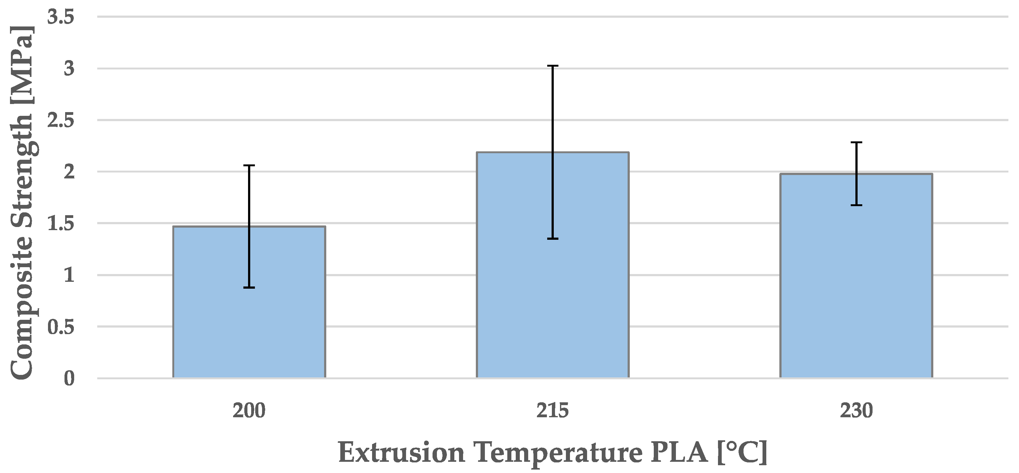
4.2.3. Influence of Extrusion Temperature
Lastly, the influence of extrusion temperature of the PLA at the interface layer was investigated. Since ambient temperature was expected to have a negligible influence on diffusion in multi-material MEX, as shown in
Section 4.1, the extrusion temperature of the second material was one of the only process influences that might have affected interface strength through diffusion. However, diffusion was not the only mechanism of adhesion that was influenced by extrusion temperature. Since the viscosity of molten polymer is temperature dependent, mechanical adhesion might also have been affected by extrusion temperature, as a less viscous material might be able to more efficiently fill the microscopic pores at the surface.
Figure 11 shows the corresponding composite strength for temperatures between 200 °C and 230 °C.
The graph shows the influence of extrusion temperature on composite strength. While raising the temperature from 200 °C to 215 °C resulted in an increase of about 50%, increasing the temperature from 215 °C to 230 °C did not further increase the composite strength, even though standard deviation decreased significantly. Due to this high standard deviation, a one-way ANOVA analysis showed no significant influence of temperature on composite strength (p = 0.201). However, some influence is expected to exist due to the mechanisms of diffusion and mechanical adhesion. While the theory of diffusion suggests that the diffusion current should increase with increasing extrusion temperatures, mechanical adhesion was not expected to increase further once almost all the pores were filled sufficiently and the interlocks were formed. Hence, it is suspected that the initial strength increase due to mechanical adhesion was small, while the effect of increased diffusion was minor in comparison. However, the latter may be the reason for the reduced of standard deviation. Nonetheless, more experiments regarding extrusion temperature are necessary to determine the effect on interface strength for the combination of ABS and PLA.
Nevertheless, further increasing the extrusion temperature, even above the range recommended by the manufacturer, is expected to increase the rate of degradation of the polymer and result in decreased composite strength due to the formation of a weak boundary layer. In addition, the different shrinkage of PLA and ABS would become more severe the higher the temperature difference between printing temperature and ambient temperature, further weakening the interface strength. The existence of a weak boundary layer or thermal stresses at the interface requires further investigation.
5. Conclusions
The results show that proper nozzle distance, line placement, and extrusion temperature are large factors affecting the composite strength of multi-material MEX components, while build chamber temperature only negligibly affects interface strength. This necessitates increased requirements for printer design and calibration for multi-material manufacturing, as deviations in the temperature or position of the nozzle can affect the interface quality. When designing multi-material 3D printer architecture, special focus needs to be placed on the calibration of the nozzle placement in z-direction. Likewise, calibration in the XY-direction has a large effect on line placement, which, in turn, affects composite strength as shown. Once again, printer architecture must allow for precise calibration in order to avoid small deviations that can have larger effects on composite strength. In addition, multi-nozzle printers should be designed with a high repeatability of the nozzle-switching process in mind so as to not affect the strength of the resulting multi-material part. Since nozzle distance has been shown to have a large effect on composite strength and is effectively equivalent to a difference in extrusion rate, other factors affecting extrusion need to be as precise as possible in order to ensure optimal composite strength. This includes extruder steps, filament diameter, and nozzle pollution, so that obstructions are not caused. In addition to ensuring proper extrusion, precise temperature control would ensure proper composite strength by affecting diffusion, mechanical adhesion, and chemical decomposition.
Lastly, line placement at the interface should be chosen such that each extrusion line is directly atop and parallel to the lines of the previous layer. Ideally, this would be automated in the slicing of multi-material parts, which should then be easily implementable. However, most slicers give no special consideration to line placement, as perpendicular placement in subsequent layers has shown good results for mono-material prints, which are the main use of MEX printers.
Taking all these factors into account unfortunately means that the composite strength data obtained by tests which have not been specifically corrected for the above-mentioned factors are effectively unusable. This paper has shown that even small fluctuations caused by the switching mechanism of the MEX machine can cause a 17% difference in composite strength. While nozzle placement repeatability in the XY-direction is expected to be at most around 0.05 mm, a shift of 0.2 mm perpendicular to the line direction can result in an “aligned” configuration turning into a “shifted” configuration, which, in turn, would result in a 12% lower composite strength. Even though further experiments are necessary to determine the effect of line shifts smaller than 0.2 mm, composite strength is expected to gradually decrease when shifting small amounts from the “aligned” orientation. This means that the XY-placement also needs to be considered when interpreting composite strength results.
6. Future Prospect
Since the design of most commercially available printers do not take these factors into account in a detailed fashion, at first glance, the multi-material MEX seems ill suited for the production of multi-material products with its repeatable properties in the current state. However, proper part design might be able to lessen the impact of low repeatability. By producing interlocking multi-material structures that show a positive fit, interface strength would become obsolete so long as proper adhesion during printing can be achieved. Once a sufficient amount of layers interlock in this way, forces are mainly transmitted by the interlock as well as cohesion or interlayer cohesion. Interlocking lattice structures seem especially suited for this purpose, as they offer three-dimensional interlocking and are easily implementable through the geometric freedoms of additive manufacturing.
However, even these interlocks require initial adhesion at the first interface layer. If adhesion is too low, no 3D interlocks can form, as prints would fail in the first layer after a tool change. Proper material settings for incompatible material combinations become necessary in the case of low adhesion in order to form an interlock without failure during printing. However, depending on the material combination, even an optimal choice of printing parameters may not create enough adhesion to survive the printing of the first layer. In such a case, plasma treatment of the interface layer, or even a third material showing adequate adhesion to both interface materials, can increase adhesion at the relevant layer and facilitate the printing of the interlock. In such a case, a reduction in the effect of plasma treatment or the decomposition of the third material over time becomes irrelevant, as forces are transmitted by the interlock once manufacturing is complete.
Lastly, such an interlock might even be achievable by other means that do not directly involve tool switches in each layer. By producing a lattice structure out of one material, bringing the second nozzle close to the top of the structure, and then filling it by extruding into the negative area (similar to injection molding), interlocking structures could be produced with a single tool change. In order to produce a surface that is suited to have the next additive layer printed on top, however, an ironing step is necessary. Nonetheless, this process usually creates a surplus or lack of material depending on the extruded amount and the flow of material into the printed lattice made from a different material. While a lack of material would probably negatively affect the strength of the interlock, excess material needs to be transported from the interface zone. While ironing the surface with the hot nozzle can remove some material, it is usually smeared to neighboring areas. Air pockets in the vicinity of the interlock zone might be able to hold this excess material, although they do not contribute to interface strength.


 ,
, 


