1. Introduction
As global oilfield development gradually enters the mature stage, the number of water injection wells continues to increase, and the real-time intelligent control of water injection wells has become a major challenge in the current industry. Although traditional wired downhole water injection control systems can adjust the water injection operation, they have caused problems in actual operations due to complex equipment, difficult operations, and high risks and have affected the normal operation of production wells. Additionally, cable wear in wells has brought high maintenance costs [
1,
2,
3]. Given the heavy workload of maintaining a large number of water injection wells and the difficulty of comprehensive consideration for each well, the development of an efficient downhole wireless real-time control system has become an urgent task for solving water injection issues [
2,
3]. Currently, there are mainly three types of wireless transmission technologies globally: mud pulse, acoustic wave, and electromagnetic wave. Mud pulse, due to its characteristics, cannot achieve bidirectional communication. Acoustic wave transmission carries less information and is easily disturbed by noise, and placing multiple relays is costly. Electromagnetic wave transmission technology, due to its simple operation and low cost, has been widely applied in Measurement While Drilling (MWD) work [
4,
5]. Electromagnetic wave transmission in wells is affected by various factors such as the transmission frequency, dimensions of the drill string and casing, and the resistivity of the formation and drilling fluid. To accurately control and optimize the propagation characteristics of electromagnetic signals, it is crucial to consider these factors comprehensively and select the appropriate excitation method. There are three common methods of motivation as shown in
Figure 1.
The first method involves installing an insulating sub between two drill pipes to form an asymmetric dipole antenna. Although this requires high standards of insulation performance and mechanical strength, with the development of high-performance insulated subs, this model has been widely applied in various scenarios. The second method is to wind a helical coil on the drill pipe without severing it, which has superior mechanical strength, low costs, simplicity of manufacturing, and convenience in operation. Although its excitation effect is slightly inferior compared with the other two methods, it can still play a key role in specific situations. The third method is achieved by slipping a magnetic core helical loop over the drill pipe. The generated field is similar to the first method, but the effect is better than the second method. Despite being influenced by various factors such as the number of coil turns, size, and magnetic permeability of the core, it is cost-effective, less prone to damage, and has good stability. Therefore, it has a wide range of applications in multiple domains, such as short-range transmission and relay transmission [
6]. Lu [
7] described in detail the working principle of the relay station and compared the attenuation characteristics of magnetic excitation and electrical excitation. The study found that magnetic excitation attenuated more quickly, and Lu [
7] also conducted an in-depth analysis of the position of the relay. Song [
8] used the equivalence theory to equate the helical loop with a magnetic loop and applied the finite element method to study the attenuation characteristics of the helical loop antenna for near-bit short-range wireless transmission technology, providing a solid theoretical foundation for near-bit measurements. Li and Sun [
9] proposed a method of adding a thin metal layer outside the helical coil, effectively solving the problem of damage to helical loop antennas during downhole operation. They also used extremely low-frequency electromagnetic waves to excite TEM waves, achieving longer-distance transmission under the conditions of multiple relays. Deng [
10] optimized the parameters of downhole transmitting antennas using magnetic loop excitation technology, initially proposing a solution to the issue of electromagnetic wave signal attenuation caused by metal casings.
Research on electromagnetic wave wireless transmission often focuses on the wireless transmission technology itself, such as Electromagnetic Measurement-While-Drilling technology. However, for downhole wireless control systems, the transmitting antennas are typically placed in environments surrounded by metal casings. Due to the unique properties of these casings, they greatly influence downhole measurements and transmissions. Current research on the effects of metal casings on EM wave signal transmission is relatively scarce, and the underlying mechanisms of how casings affect EM waves are unclear. While the acquisition of real-time downhole dynamic data can significantly aid technical personnel in taking timely measures, especially in guiding development and production, field tests have shown that EM wave transmission distances in cased wells are usually shorter than in open-hole wells. At the same depth, the intensity of EM signals received at the surface is often weaker in cased wells.
Moreover, the complexity of the downhole environment renders the signal attenuation patterns of helical loop antennas unclear, posing challenges to the design and deployment of downhole wireless control systems.
This paper focuses on exploring the optimization of a third type of helical loop antenna for EM wave transmission. Employing the principle of equivalence, we treat the helical loop transmitting antenna as a point magnetic dipole source, replacing the physical helical loop antenna with an imposed magnetic dipole current. On this basis, a two-dimensional axisymmetric model has been established to clearly define the key mechanisms by which metal casings affect EM wave transmission and propose corresponding solutions to improve the efficiency of EM wave wireless communication transmission. Further, this study delves into the signal transmission characteristics of EM waves in cased wells. By applying the theory of equivalence, we have not only improved the efficiency of model establishment and solution but also provided a new perspective for understanding and resolving practical EM wave transmission issues in operational settings.
2. Theoretical Analysis and Improvement Research on Finite Element Models
2.1. Finite Element Analysis
For low-frequency electromagnetic field problems, three methods are commonly used for simulation calculations [
11,
12,
13,
14]: the Difference Method (DM), Transmission Line Matrix Method (TLM), and Finite Element Method (FEM) [
15]
Among them, the Difference Method is highly regarded for its accurate calculation results. However, since it requires the calculation of every node in space, it can be quite time-consuming and thus demands high computer performance. This method can become quite complex when dealing with irregular boundaries.
The Transmission Line Matrix Method [
16] can be considered as a variant of Maxwell’s equations under certain boundary conditions. It shows particular advantages when dealing with high-frequency electromagnetic field problems. However, for low-frequency electromagnetic fields, this method may produce large errors.
Finite Element Analysis is the current focus of research, with various finite element software emerging. Its core idea is to discretize the continuous domain into a finite number of elements and to approximate the solution of the original differential equation by successive calculations for each element. This method focuses on extremum within discrete elements, demonstrating outstanding computational capability when dealing with models that have complex boundary conditions. In complex subsurface environments, the heterogeneous distribution of formation conductivity and complexity of boundary structures are common issues. The Finite Element Method can flexibly combine these boundary conditions, accurately calculating electric and magnetic fields at any position within the model and ensuring high precision in the solution.
2.2. Theory of Finite Element Analysis for Electromagnetic Fields
Maxwell’s equations are crucial for understanding and analyzing the issues of electromagnetic wave propagation in well bores. When studying the short transmission problems of downhole electromagnetic waves, a helical loop antenna is excited by a current source. In this context, the electromagnetic field is a time-harmonic field, and the instantaneous field vectors are differentiated with respect to time. The Maxwell’s equations can be expressed in the following form:
where
is the electric field intensity,
is the magnetic flux density,
is the magnetic field strength,
is the electric displacement field,
denotes the conduction current density,
ω is the angular frequency,
μ is the magnetic permeability, and
ρ0 represents the electric charge distribution in space.
By substituting Equation (3) into Equation (4), the wave equation for a time-harmonic field can be obtained, which serves as the governing equation for finite element analysis:
where
k0 is the wave function in free space, and
is the external current density. It is clear that for analyzing low-frequency electromagnetic field problems, obtaining the current density in the loop and the transmission potential is sufficient.
The ideal boundary conditions for the drill string are set as follows:
where
is the outward unit normal vector to the boundary.
Since the drilling fluid and formation are not ideal conductors, the boundary conditions at the interface are set as follows:
The boundary conditions at the location of the transmitting antenna are as follows:
where
represents the imposed current density.
When using the finite element method to simulate electromagnetic field problems, it is common to model domains with open boundaries, where the electromagnetic waves pass through the boundaries without reflection. To accomplish this, first-order scattering boundary conditions are set up:
By incorporating the aforementioned boundary conditions into Equation (4) and based on the variational principle, the functional expression can be derived as follows:
When solving a functional, it is necessary to discretize the domain of interest into a number of subspaces. For each element, field quantity solution expressions are derived using shape functions within the local coordinate system. This process results in the assembly of the global matrix equation: [K] [X] = [P], where [K] represents the global stiffness matrix, [P] denotes the applied conditions, and [X] is the vector of unknown variables to be solved for. By solving for the large sparse matrix within this global matrix equation, the electromagnetic field distribution across the entire domain can be obtained.
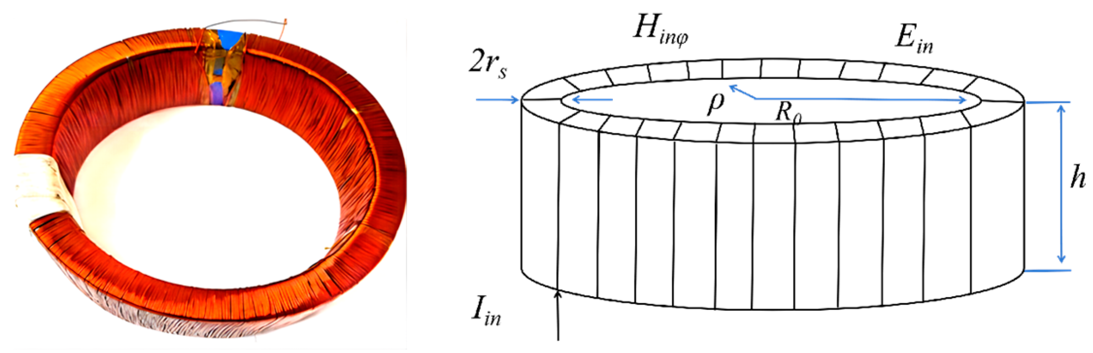
2.3. Helical Coil Excitation Calculation
As shown in
Figure 2, according to Ampere’s circuital law, the magnetic field
Hinφ inside the helical coil, which is induced by the current source
Iin satisfies the following condition:
According to Faraday’s law of electromagnetic induction, it is known that the relationship between the magnetic field and the electric field at any point within the helical coil is as follows:
Inside the helical coil, because the magnetic field in the
φ direction is equal, the magnetic flux caused by the magnetic field at any point on the
ρz plane is equivalent to a point source of magnetic current in the
φ direction, which means:
Therefore, in simulation modeling, a magnetic current loop can be used to equivalently replace the helical coiled loop antenna, which provides a reliable method for efficiently simulating and analyzing electromagnetic wave transmission.
Where:
The total equivalent magnetic current
IM of the helical coil can then be obtained by integrating
Im:
Bringing (13) into (14) gives
Referring to Equation (15), we understand that a linear relationship exists between the total magnetic current of the helical loop antenna and the applied current, given a fixed number of turns, dimensions, and core permeability. In practical applications, this implies that we can precisely calculate the required magnetic current for simulation environments by pre-setting the number of turns, cross-sectional area, and core permeability of the helical loop and adjusting the magnitude of the input current. Consequently, the magnetic current values used in simulations can also provide direct guidance for the customized design of the helical loop antennas.
2.4. Element Geometric Modeling
The electromagnetic wave transmission channel encompasses several components, including the drill string, drilling fluid, casing, and formation [
17]. Assuming the formation is a homogeneous medium with isotropic parameters, the model can be simplified for analysis. The entire drill string is considered a uniform structure with consistent inner and outer radii, disregarding the structure of couplings but accounting for conductivity and permeability changes due to contact. The modeling of the metal casing is consistent with that of the drill string and is connected to the external formation. The drilling fluid between the metal casing and the drill string is also assumed to be isotropic. The transmitting antenna is a helical loop mounted on the drill string, and the receiving antenna is another helical loop spaced at a certain distance. The helical loop wireless transmission model is shown specifically in
Figure 3.
Considering the symmetrical nature of the model, we constructed a two-dimensional axisymmetric model [
9]. The helical loop antenna is represented by a point magnetic dipole source at its position, and by measuring the magnetic field amplitude at varying intervals, the voltage signals at different locations can be calculated.
2.5. Meshing
For structures with high contrast, such as the drill string, casing, and drilling fluid, we constrain the size and number of boundary meshes. The formation and air use free triangular meshes. Scattering boundary conditions are applied to the boundaries of the solution domain, and boundary layer meshes are utilized. Around the point magnetic dipole source location, a small rectangular area is set, and the mesh is refined. To enhance the efficiency of the solution, we only refine the mesh at the boundaries of the drill string and casing, while the rest of the mesh progressively coarsens as the distance from the casing increases.
3. Results and Analysis of Influencing Factors
3.1. Reception of Helical Loop Antenna Signals
According to Faraday’s Law of Electromagnetic Induction,
Thus, the induced electromotive force (EMF) of the helical loop is
From
(17), we have
N: number of turns of the coil; S: cross-sectional area of the coil; f: transmitting frequency; μ: magnetic permeability of the core.
The magnitude of the induced electromotive force in a helical loop depends on factors such as the number of coil turns, the magnetic permeability of the core, and the frequency. When considering a fixed receiving coil, its number of turns, core, and area are constant, so there is a direct proportional relationship between the induced EMF and the magnetic field strength.
At the same frequency, by just calculating the amplitude of the received magnetic field at different transmission distances, one can determine the voltage at the corresponding positions. To more accurately assess the impact of various parameters, this paper employs the method of controlling variables, which is to say, ensuring all other parameters remain unchanged when discussing a particular parameter.
3.2. The Influence of Frequency on Signal Attenuation
Using the model in
Figure 3, the drill string is set to be 240 m in length, with an inner diameter of 46 mm and an outer diameter of 76 mm. The casing is 240 m in length, with an inner diameter of 124 mm and an outer diameter of 154 mm. The electrical conductivity of both the drill string and casing is 1.12 × 10
7 S/m. The drilling fluid’s resistivity is set at 1 Ω·m with a relative permittivity of 80, while the formation resistivity is set at 10 Ω·m. The helical loop antenna is installed at a position 10 m above the bottom of the drill string. A magnetic current excitation of 1 V is applied, and the frequency range of the short transmission signal studied is set from 10 Hz to 10,000 Hz. The relationship between transmission frequency and received magnetic field amplitude is shown in
Figure 4a. According to:
, Let
, the relationship between the transmitting frequency and the signal is as shown in
Figure 4.
Frequency has a significant impact on the propagation of electromagnetic waves, especially higher frequencies leading to more severe attenuation. For instance, over a propagation distance of 100 m, as the transmitting frequency increases from 10 Hz to 10,000 Hz, the signal attenuation rapidly climbs from 33.1 dB to 233 dB. This indicates that using extremely low frequencies for transmission is more appropriate when covering longer distances. However, at shorter transmission distances, such as 70 m or 40 m, high-frequency transmission demonstrates its advantages.
When electromagnetic wave signals propagate through a cased well, reducing the transmitting frequency is an effective way to increase the signal’s propagation distance. Although high-frequency electromagnetic signals have limited transmission distances, they exhibit advantages unmatched by low-frequency signals for short-range transmission. In practical applications, it is necessary to consider both transmission distance and rate, finding a balance between frequency and transmission power. In this study, after analysis, the frequency of 1000 Hz has been chosen as the standard frequency, which meets the transmission distance requirements of the researched content. All subsequent model experiments will use this frequency unless otherwise specified.
3.3. The Impact of Drilling Fluid Resistivity on Signal Attenuation
Due to the variations in the geological environment of different regions, the characteristics of the drilling fluids in water injection wells also differ significantly. Therefore, the resistivity of the drilling fluid is set between 0.1 Ω·m and 100 Ω·m, and the relative dielectric constant is set to 80, with other settings the same as in
Section 3.2.
As shown in
Figure 5, Data analysis shows that when the resistivity of the drilling fluid is 0.1 Ω·m, the electromagnetic wave signal attenuates by 270.4 dB after traveling 100 m; when the resistivity increases to 1 Ω·m, the attenuation decreases to 133.1 dB; and further increasing to 10 Ω·m, the attenuation is only 41 dB. This reveals a trend: as the resistivity of the drilling fluid increases, the attenuation of the electromagnetic wave signal gradually decreases. However, it is worth noting that at shorter transmission distances, even though the electromagnetic wave signal attenuates more in low-resistivity drilling fluids, its transmission effect is actually better than that in high-resistivity drilling fluids. Therefore, in practical operations, the relationship between the intended transmission distance and the resistivity of the drilling fluid should be considered comprehensively to achieve the best transmission effect.
3.4. The Impact of Formation Resistivity on Signal Attenuation
In cased wells, the formation is a component of the transmission channel, and studying the impact of changes in formation resistivity on signal attenuation patterns is equally meaningful. The drilling fluid resistivity is set at 1 Ω·m with a relative permittivity of 80, and the range of formation resistivity is set between ρ = 0.01 Ω·m and 100 Ω·m.
According to
Figure 6, variations in the formation resistivity have almost no effect on the attenuation and magnitude of the signal within the well. The casing, acting as a conductor, can effectively reflect and absorb the magnetic field, producing a strong shielding effect on the internal magnetic field, thus limiting the diffusion of the magnetic field in the external medium. As a result, the magnetic signal inside the well is not affected by changes in the resistivity of the medium outside the casing.
3.5. The Impact of Drill String Properties on Signal Attenuation
The drill string is composed of drill pipes, each about 9 m in length, strung together. As the drilling depth increases, the number of drill pipes connected in series needs to be continuously added. There is contact resistance at the connection between drill pipes, and the drill string itself is not an ideal conductor; its electrical conductivity and relative magnetic permeability both vary. Moreover, the dimensions of the drill string may differ in different wells. Therefore, it is necessary to delve into the impact of factors such as electrical conductivity, magnetic permeability, dimensions of the drill pipes, and contact resistance on signal transmission.
3.5.1. The Impact of Drill String Conductivity on Signal Attenuation
The model is consistent with the previous model. Since drill pipes are generally made of steel, the range of drill string conductivity is set between 1 × 10⁶ S/m and 1 × 10⁸ S/m, with the relative magnetic permeability set to 100.
Figure 7 reveals the correlation between drill string conductivity, signal attenuation, and reception strength. As the conductivity increases, the signal attenuation gradually decreases, and the strength of the received signal correspondingly increases. When the transmission distance is 100 m, the signal attenuation for a drill string with conductivity of 1 × 10
6 S/m is 195.01 dB, while for a drill string with conductivity of 1 × 10
7 S/m, the signal attenuation is 135.4 dB, with a difference of 62.65 dB in the received magnetic field amplitude at 100 m. This phenomenon highlights the importance of the drill string as the main transmission channel for electromagnetic waves. With the increase in conductivity, the amplitude of the received magnetic field tends to stabilize. However, it is worth noting that the reliability of the connections at the drill pipe joints has a significant impact on conductivity and consequently affects the transmission efficiency of the signal. Therefore, in engineering practice, ensuring the stability of the drill pipe joint connections is vitally important to maintain the overall transmission efficiency of the system.
3.5.2. The Impact of Drill String Magnetic Permeability on Signal Attenuation
The magnetic permeability of the drill string is one of its key characteristics. When studying its impact on drill string performance, we set the electrical conductivity of the drill pipe at 1 × 10⁷ S/m and focused on the parameter of relative magnetic permeability in the model. Since drill pipes are mainly composed of iron and alloys, we set the range of their relative magnetic permeability between 1 and 1000 to more accurately simulate and analyze their performance in practical applications.
According to
Figure 8, with the increase in relative magnetic permeability, the attenuation of the magnetic field also shows a significant increase. Taking the transmission distance of 100 m as an example: when the relative magnetic permeability of the drill pipe μ = 1, the signal attenuation is 95.01 dB; at μ = 10, the attenuation increases to 104.94 dB; at μ = 100, the attenuation further intensifies to 132.99 dB; and at μ = 1000, the signal attenuation reaches even greater, at 158.7 dB.
This phenomenon is closely related to the material of the drill string. If the drill string is made of materials with high magnetic permeability (such as iron, steel, and other ferromagnetic materials), electromagnetic waves experience greater attenuation while transmitting around the drill string, leading to reduced efficiency of long-distance propagation and increased transmission difficulty. In the design of communication equipment, the influence of the drill pipe’s magnetic permeability on the propagation characteristics of electromagnetic signals must be fully considered.
3.5.3. The Impact of Drill String Dimensions on Signal Attenuation
Under different drilling conditions, the dimensions of drill pipes vary. Common diameters of drill pipes are 60 mm, 73 mm, and 89 mm, among others. With the drill pipe wall thickness and casing size kept constant, it has been observed that as the diameter of the drill pipe increases, the attenuation of the electromagnetic wave signal correspondingly intensifies. According to
Figure 9. Taking the transmission of 100 m as an example, the signal attenuation is 118.2 dB for a drill pipe with an outer diameter of 60 mm, 128.96 dB for 73 mm, and reaches 141 dB for 89 mm. However, within a transmission range of 20 m, the received signal gradually strengthens with the increase in drill pipe diameter. But beyond 20 m, an increase in drill pipe diameter actually leads to a weakening of the received signal. Therefore, in short-distance transmission, choosing a drill pipe with a larger diameter may have advantages, while for long-distance transmission, thinner drill pipes may be more conducive to the propagation of electromagnetic waves.
3.6. The Impact of Casing Properties on Signal Attenuation
Electromagnetic wave transmission in wells with casing often results in shorter distances and relatively weaker signal strengths. To gain a deeper understanding of the mechanism by which metal casing affects electromagnetic wave transmission, it is necessary to conduct a detailed exploration of factors such as casing conductivity, relative magnetic permeability, and inner diameter.
3.6.1. The Impact of Casing Conductivity on Signal Attenuation
When the casing conductivity is equal to 1 S/m, it indicates that there is no casing in that region, and the conductivity is consistent with that of the drilling fluid. As can be seen from
Figure 10 in an open-hole well environment, the attenuation of the signal is smaller, with a 63.29 dB attenuation after 100 m of transmission. The presence of casing increases signal attenuation. However, as casing conductivity increases, signal attenuation gradually decreases. Specifically, when the casing conductivity is increased to 1 × 10
6 S/m, the attenuation of the electromagnetic wave signal after 100 m transmission is 176 dB; at a conductivity of 1 × 10
7 S/m, the attenuation is 132 dB; and when conductivity reaches 1 × 10
8 S/m, the attenuation is only 11.3 dB. Although signal attenuation is smaller without casing, within a short distance of 10 m, the signal amplitude received with casing is larger. This is because, in addition to causing electromagnetic wave attenuation inside it, the metal casing also has waveguide characteristics that can assist energy transmission over short distances, making the received electromagnetic signal stronger compared to that in an open-hole well.
The strong attenuation of the magnetic field within the casing means that effective transmission can only take place over short distances. Therefore, in the absence of relay assistance, the single-stage transmission distance will be significantly limited.
3.6.2. The Impact of Casing Magnetic Permeability on Signal Attenuation
Casing magnetic permeability is a crucial attribute. When studying its impact on the signal, the casing conductivity is set at 1 × 10
7 S/m, and the relative magnetic permeability is adjusted within a range of 1 to 1000. As shown in
Figure 11, taking the transmission of electromagnetic waves over 100 m as an example, we can observe: when μ = 1, the signal attenuation is 109 dB; when μ = 10, the attenuation is 114 dB; when μ = 100, the attenuation reaches 130 dB; when μ = 500, the attenuation is 142.3 dB; and when μ = 1000, the attenuation is 145 dB. These data show that with the increase in casing relative magnetic permeability, signal attenuation actually tends to intensify. In other words, the greater the magnetic permeability, the smaller the amplitude of the received magnetic field and the greater the attenuation.
3.6.3. The Impact of Casing Dimensions on Signal Attenuation
Under different drilling conditions, the selected casing sizes may vary. Common casing inner diameters include 139 mm, 177 mm, 219 mm, and so on. To investigate the impact of casing inner diameter on signal transmission, we have specified a range of diameters from 11 cm to 21.9 cm with a wall thickness of 10 mm. For a transmission distance unit of 100 m, when the casing inner diameter L = 110 mm, the signal attenuation is 151 dB; at L = 130 mm, the attenuation drops to 124 dB; and at L = 219 mm, the attenuation further decreases to 91 dB. Clearly, signal attenuation gradually diminishes as the inner diameter increases.
As shown in
Figure 12, within a distance of 10 m, a smaller casing diameter provides larger values of the received magnetic field; however, beyond 10 m, a larger casing diameter can receive greater magnetic field amplitudes. This indicates that the casing’s inner diameter plays a crucial role in the transmission of electromagnetic waves, affecting not only the degree of signal attenuation but also directly influencing the strength of the received signal.
When the spacing between the casing and the drill string is close, electromagnetic wave attenuation is greater, but the signal received in short-distance transmission remains stronger; conversely, at greater distances, signal attenuation is less, enabling a farther transmission distance.
3.7. The Influence of Helical Loop Position
The position of the helical loop antenna has a certain degree of uncertainty, and we need to investigate its relationship with signal transmission. By calculating the amplitude of the received magnetic field and the signal attenuation, it is found that the length of the drill string below the helical loop has a significant impact on signal reception as shown in
Figure 13. Specifically, when the lengths of the drill string below the helical loop are 1 m, 5 m, and 10 m, respectively, the amplitude of the received signal at the same transmission distance shows an increasing trend. Notably, when the length of the drill string is increased to 10 m, the amplitude of the received signal reaches its maximum. It is important to note that when the helical loop is moved further up, the amplitude of the received signal no longer changes significantly.
The result of this study suggests that increasing the length of the drill string within a certain range below the helical loop has a positive effect on signal reception. Therefore, in practical applications, to optimize the transmission and reception quality of the signal, it is recommended to set the length of the drill string below the helical loop to more than 10 m.
4. Field Test
To verify the accuracy of the simulation response and to further investigate the mechanism of electromagnetic wave propagation underground, this study conducted a communication experiment targeting the helical loop antenna in an experimental well at a certain oilfield. As shown in
Figure 14. The experimental design included two main parts: downhole transmission and reception. The experiment was validated using a specially designed external drill string component combined with a precise internal instrument assembly. The external assembly mainly consisted of a tool joint sub, a suspension sub, and the helical loop antenna, while the internal assembly was arranged in sequence with a top-end assembly, transmitter, power supply battery, and lower metal centralizer.
In a cased well with a wide diameter of 150 mm and a depth of approximately 500 m, where the inner wall suffered from severe corrosion, the experimental setup was deployed. The water level in the well was measured at a depth of 10 m to 15 m, and the mud resistivity was determined to be 0.98 Ω·m; appropriate experimental parameters were set accordingly. The experiment utilized two sets of helical loop antennas, each with 100 turns and a cross-sectional area of 2.5 cm2. The transmitter power was adjusted to 8 watts, and a frequency of 1000 Hz was used for signal transmission.
At a depth of 100 m below ground level, the transmitting antenna was fixed, and the distance to the receiving antenna was gradually increased from this base point. The preliminary spacing between the antennas was set at 20 m, and it was subsequently increased to 30 m, 40 m, 50 m, and 60 m. After each adjustment, the experiment waited for the receiving antenna to stabilize and record the waveform before proceeding. To ensure the accuracy of the data and reduce the impact of random errors, signal recordings at each interval were collected multiple times and averaged.
Such a rigorous experimental process ensured the controllability and reproducibility of the experimental conditions, providing quantitative data for assessing the communication efficiency and signal quality of the helical loop antenna in specific underground environments, as well as an experimental basis for validating and optimizing the simulation model.
Figure 15 is a comparison of well logging results with the calculation results for the experimental well in the oilfield. It is evident from the figure that the calculated results show the same trend with the change in depth as the experimental measurements, and the calculated values at the same depth points are not significantly different from the measured values, verifying the correctness and applicability of the model. The deviations between the calculated values and the measured values at the same depth points are mainly caused by two factors: one is the model’s simplified treatment of the formation, and the other is that the parameters in the model cannot be accurately obtained and only approximate values are used for the calculations.
The simulation data and experimental data show good consistency, further validating the correctness of the theory. The theoretical research can be used to optimize and design electromagnetic wave transmission for water injection wells.
5. Conclusions
Based on electromagnetic theory, this study has developed a finite element model centered around the helical loop antenna to focus on the signal transmission mechanism within cased wells. Through in-depth research of electromagnetic wave wireless transmission theory in cased wells, we have successfully derived a comprehensive attenuation theory, which has been verified and applied in an underground wireless real-time control system. Using the finite element method, a theoretical model of helical loop signal transmission was constructed, and the calculated results were extensively compared and analyzed with actual field measurement data. The results show that the model is not only highly reliable but also demonstrates widespread applicability in practical applications. The frequency of the electromagnetic signal determines its propagation characteristics. Low-frequency signals, due to less attenuation, can cover a broader area, whereas high-frequency signals are limited in long-distance transmission but more efficient in short-distance transmission. Electromagnetic wave signal transmission is significantly affected by the resistivity of the drilling fluid. With low-resistivity drilling fluid, signal transmission over short distances is enhanced. The magnetic permeability of the drill string has a notable impact on electromagnetic wave transmission, particularly at high magnetic permeability, where it may limit the effective propagation of signals. The diameter of the drill string is crucial for signal transmission. A thicker drill string diameter facilitates rapid signal transmission over short distances, while a thinner drill string diameter is more suitable for long-distance communication. Similarly, casing size also affects signal propagation, with larger casing sizes aiding signal transmission over longer distances and smaller casing sizes exhibiting higher rates over short distances. The placement position of the helical loop antenna is crucial for signal transmission efficiency. If it is too close to the bottom of the drill string, it may hinder the effective propagation of electromagnetic waves, thus affecting communication quality.
The research presented in this paper not only deepens our understanding of the rules of electromagnetic wave transmission in cased wells but also provides more efficient and intelligent guidance for future oilfield development, contributing to the ongoing development of the petroleum industry.


