Article

Turning Data Center Waste Heat into Energy: A Guide to Organic Rankine Cycle System Design and Performance Evaluation

by
Orlando Corigliano
,
Angelo Algieri
* and
Petronilla Fragiacomo
Department of Mechanical, Energy and Management Engineering, University of Calabria, 87036 Rende, Italy
*
Author to whom correspondence should be addressed.
Appl. Sci. 2024, 14(14), 6046; https://doi.org/10.3390/app14146046
Submission received: 29 April 2024 / Revised: 28 June 2024 / Accepted: 10 July 2024 / Published: 11 July 2024
(This article belongs to the Special Issue The Transition toward Clean Energy Production 2024)

Abstract

:
This study delves into the adoption of the organic Rankine cycle (ORC) for recovering waste heat from data centers (DCs). Through a literature review, it examines energy reuse with a focus on electric power generation, the selection of working fluids, and system design principles. The objective is to develop a thorough framework for system design and analysis, beginning with a quantity and quality investigation of waste heat available. Air cooling systems, chosen often for their simplicity, account for about 70% of used cooling methods. Water cooling demonstrates greater effectiveness, albeit less commonly adopted. This study pays close attention to the selection of potential working fluids, meticulously considering the limitations presented by the available sources of heat and cold for vaporization and condensation, respectively. It reviews an ORC-based system setup, incorporating fluid streams for internal processes. The research includes a conceptual case study where the system is designed and simulations are conducted in the DWSIM environment. The simulation model considers hot air or hot liquid water returning from the data center cooling system for ORC working fluid evaporation. Ambient water serves for condensing, with pentane and isopentane identified as suitable organic fluids. Pentane assures ORC net electric efficiencies ranging between 3.1 and 7.1% when operating pressure ratios increase from 2.8 to 6.4. Isopentane systems, meanwhile, achieve efficiencies of 3.6–7.0% across pressure ratios of 2.7–6.0. Furthermore, the investigation provides key performance indicators for a reference data center in terms of power usage effectiveness (PUE), energy reuse factor (ERF), energy reuse effectiveness (ERE), and greenhouse gas (GHG) savings. This study concludes with guidelines for system analysis, including exergy considerations, and details the sizing process for evaporators and condensers.

1. Introduction

Waste heat recovery (WHR) technologies play an essential role in enhancing the efficiency of various processes by capturing and utilizing energy that would typically be lost to the environment [1,2]. Unfortunately, conventional power generation methods fall short in converting low-quality waste heat into usable electric energy, leading to a substantial loss. By recovering this waste heat, not only can electric generation become more cost-effective, but it also contributes to reducing pollution.
In the low-quality thermal recovery field, organic Rankine cycle (ORC) technology has emerged as a suitable solution for power production [3,4,5]. To this end, this paper aims to harness the waste heat generated from the equipment of data centers to support a Rankine-based energy cycle, contributing to clean production and effective energy transition.
This work supports the objectives of the Energy Efficiency Directive (EED) [6], which mandates that data center operators monitor and submit key performance indicators (KPIs) to the European database every year to reduce their energy footprint. This directive highlights the growing significance of the information and communication technology (ICT) sector. In 2018, EU data centers consumed 76.8 TWh of energy, a figure anticipated to climb substantially by 2030. Predictions made in 2018 suggested a 28% increase, but with advancements in artificial intelligence (AI) technologies, some nations could experience a doubling or even tripling of this consumption. For instance, the International Energy Agency (IEA) [7] projects that by 2030, Ireland might witness a nearly 2-fold and Denmark a 6-fold surge in electricity demand by data centers.

1.1. Background

Data centers are dedicated facilities housing computer systems and associated components, such as telecommunications and storage systems. They serve as centralized locations for organizations to store, process, and disseminate high amounts of data, integral to the operations of businesses, government agencies, and cloud service providers [8,9].
Key components include servers, storage systems, networking equipment, cooling systems, power supplies, and security systems. Data centers vary in size and capacity, and are categorized as small, medium, or large.
DCs are significant consumers of electrical energy, accounting for about 1–3% of worldwide electricity use. A typical large data center can consume as much power as a small town, with heat output ranging from tens of kilowatts to several megawatts [8,10,11]. The high-power computing activities in data centers generate considerable heat, primarily from servers and storage units, usually wasted due to the low quality [12,13,14,15]. Cooling systems, crucial for maintaining optimal operating temperatures, can account for a substantial portion of energy use [12].
With the growing demand for data processing and storage, the need for efficient, sustainable, and scalable solutions becomes increasingly pronounced [1,16]. Accordingly, energy efficiency measures are fundamental for sustainability.

1.2. Literature Overview

The present section overviews recent studies, offering a perspective on the current state and future directions for the sustainability of data centers.
Huang et al. [14] offer a systematic literature review on DC technologies, focusing on cooling systems, renewable energy integration, and waste heat recovery. The study stands out for its holistic view of data center operations, emphasizing the importance of developing advanced control methods and performance metrics to maximize energy efficiency. In line with this, Wahlroos et al. [17] discuss the adoption of renewable energy sources and thermal management strategies, providing a strategic six-step process for creating sustainable and energy-efficient data centers.
The energy consumption and reliability modeling in data centers are other critical areas of research. An article [16] surveys recent studies on modeling data center energy consumption, concluding with the organization of a taxonomy. Ahmed et al. [10] adopt a systematic literature review methodology to dissect contributions related to energy consumption, providing a foundational tool for future research in this domain. Similarly, a study [18] examines power models for virtual machines and software applications, investigating strategies to maximize the quality of service.
Numerous reviews and research papers populate the literature in the WHR field. Already in 2014, the question of recovering DC waste energy arose: Ebrahimi et al. [12] reviewed techniques for recovering waste heat, assessing various methods, including district heating, absorption cooling, and direct and indirect power generation. The study identifies absorption cooling and the ORC as highly promising for data center applications for cooling purposes and electric generation, respectively. In particular, to the best of the authors’ knowledge, ORC technology represents the most suitable solution for electric production from DC waste heat from an energy and economic point of view, considering the corresponding low-grade thermal level and the typical operating conditions of data centers. In fact, alternative solutions based on piezoelectric and thermoelectric generation exhibit lower efficiencies, lower power, and higher costs [12]. Furthermore, comparing the Kalina cycle, trilateral Rankine cycle, and organic Rankine cycle for waste heat reuse confirms that the ORC is the proper choice for low-quality thermal energy exploitation due to its energy and economic performance [1,19]. The literature review highlights that Stirling engines can also exploit low-grade thermal sources [20,21]. However, the corresponding electric efficiency is always lower than 1% considering the typical operating conditions of DCs with source temperatures lower than 60–85 °C [22,23], suggesting that ORC adoption for the reuse of the DC low-quality waste heat is a viable option. In a similar vein, another work [3] evaluates the integration of micro-ORC systems into data center cooling systems through experimental analysis, showcasing the potential of harnessing waste heat effectively.
At the RISE ICE Data Center, research has evaluated the potential direct exploitation of the data center’s excess heat [24]. The investigation has developed a matrix illustrating different options based on the DC cooling characteristics (i.e., air-cooled, liquid-cooled), demonstrating that data centers are essential to promote industrial and urban symbiosis (IUS) through district heating, direct heating, and industrial applications. In this framework, Vesterlund et al. [25] investigated the possible adoption of low-grade excess heat from data centers as a thermal source for a small-scale mealworm farm, and Brännvall et al. [26] suggested directly utilizing the low-grade heat for fruit- and berry-drying processes in food industries. The solutions improve the value and the benefit of the electric energy used in data centers by exploiting the excess heat and reducing the energy dissipation.
Instead, the article by [1] primarily focuses on district heating achievable using heat pumps to upgrade the temperature of recovered waste heat. It presents various case studies to illustrate the practical feasibility of applying WHR technologies in district heating networks. Yakovlev and Avdokunin [27] delve into the effectiveness of ventilation systems and heat pumps in data centers, reporting the methodologies and results for calculating heat transmission under different conditions.
The economic viability of waste heat utilization is a pivotal aspect of data center sustainability. Pärssinen et al. [28] outline a modeling study to evaluate the net present value of such utilization, employing Monte Carlo simulations to assess various scenarios and their uncertainties. Complementing this, the study by [29] conducts a sensitivity analysis of the net present value (NPV) of WHR projects, identifying key factors such as initial investment cost and energy pricing that significantly impact feasibility. Furthermore, the literature [30,31] highlights that the DC waste heat recovery adopting proper ORC systems is economically feasible with typical payback times between 4 and 8 years.
The exploration of advanced energy systems for data centers is fundamental for enhancing their efficiency. Chen et al. [32] present a multi-objective thermo-economic optimization of a combined cooling, heating, and power (CCHP) system, integrating a solid oxide fuel cell and a gas turbine. Efficiency and economic performance are evaluated using the NSGA-II algorithm for optimization. A similar approach is in the study by [33], which explores the potential of hybrid data center cooling systems combined with polymer electrolyte membrane fuel cell systems. Yin et al. [34] introduce a framework that integrates internet data centers into the electric grid as energy prosumers, facilitating their participation in heat regulation. The investigation by [35] delves into the sustainability of green data centers using CCHP and waste heat reuse systems, introducing innovative energy management strategies.

1.3. Contribution

This research aims to provide a comprehensive sequence for designing energy recovery systems for data centers devoted to electric generation, transitioning from theoretical analysis to practical implementation. It serves as a contribution to the development of energy recovery solutions from low-grade heat sources.
This paper presents a comprehensive spectrum of critical information, detailing the quantity and quality of heat sources, with valuable insights and data on organic Rankine-based energy systems and their compatible working fluids for effective waste heat utilization. Its foundation is based on a diverse collection of highly cited papers and technical reports, establishing a robust framework.
As a practical handbook, this study outlines guidelines for analyzing low-grade heat recovery techniques, and their integration into bottoming ORC energy systems.
Moreover, this paper introduces a standardized blueprint for an energy system, detailing the components and performance assessment criteria and introducing a conceptual application case. The case starts with the system engineering, highlighting the process of selecting the working fluid. It then evaluates key performance indicators to test the technical and energy feasibility. The system is modeled and simulated in the DWSIM computational environment [36].
The present work aims to provide proper information for the energy exploitation of the low-quality waste heat of data centers, adopting ORC systems to improve the DC energy performance and promote an efficient transition towards a more sustainable future.

2. Materials and Methods

The approach leverages highly cited papers and technical reports to build a precise framework. Scientific databases such as Scopus, Web of Science, and Google Scholar ensure broad and thorough topic coverage. This extensive collection of sources provides the foundation for this paper’s organization and structure.
This study undertakes a theoretical approach and an exhaustive review examining heat sources in data centers and estimating the recoverable heat from their operational processes. Consequently, an overview of the viable energy recovery technologies is conducted, converging towards ORC as an eligible solution to produce electric power.
A detailed analysis of working fluids examines their thermophysical properties, availability, and environmental impact.
The focus then shifts to the design criteria of the energy system, and a standardized model for a prospective energy plant develops a blueprint for discussing the various components and their roles within the system. Following this, the criteria for analyzing the thermodynamic cycle are detailed, emphasizing efficiency and practical applicability.
This research then transitions into an application phase, shifting from heat recovery and thermal source analysis to engineering a functioning system and assessing its performance at the plant level. This phase is augmented by drafting guidelines for selecting the optimal working fluid through exergy analysis and detailing the process for sizing the evaporator and condenser.
The approach follows energy engineering design principles, adopting the DWSIM software (version 8.7.1) for process engineering. This tool assists in designing the system and conducting calibration tests. Following this, simulations evaluate thermodynamic parameters and assess energy performance.

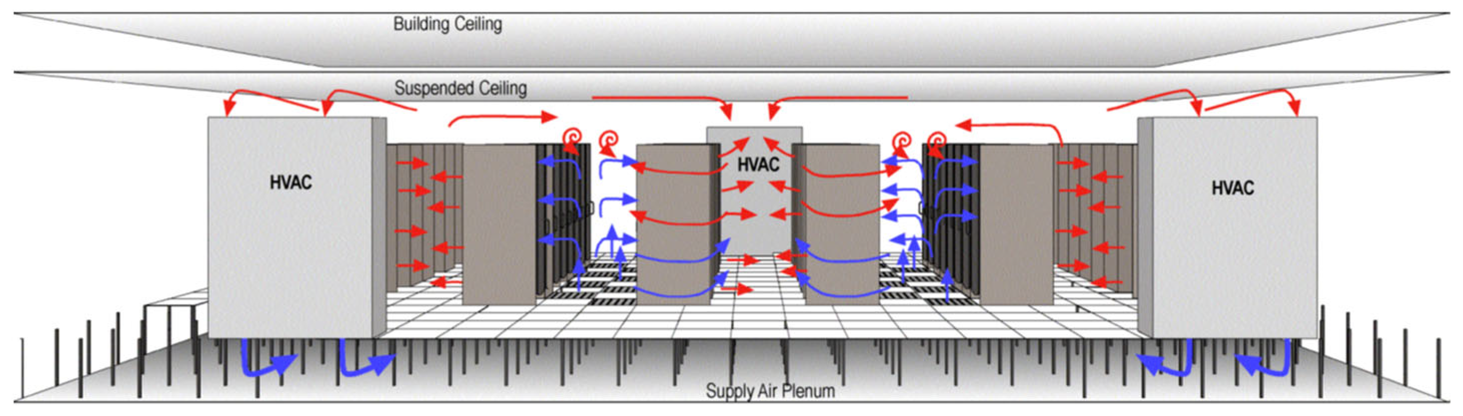
3. Power Consumption, Heat Fluxes, and Cooling in Data Centers

Data centers are responsible for approximately 3% of global electricity consumption and contribute to around 4% of total greenhouse gas (GHG) emissions [37].
The electric demand has seen a significant upsurge, increasing by at least ten-fold [9]. Past estimates projected a demand of 8–15 kW/m2 for the current decade [38]. Modern data centers feature servers with power densities ranging from 0.5 to 2 kW/m2, leading to power requirements of up to 30 kW per rack. Interestingly, these servers consume at least 60% of their nominal power even to maintain standby mode. In the United States alone, energy consumption has grown from 28 billion kWh in 2000 to an estimated 140 billion kWh in 2020 [39]. High-density facilities reach consumption rates equal to 40 kW/m2, while extremely dense communication equipment has seen rates as high as 96 kW/m2 [40].
The primary energy consumers within these centers are information technology (IT) equipment and their associated heating, ventilation, and air conditioning (HVAC) systems. Operations lead to heat generation, whose management is one of the most critical challenges. Estimates indicate that cooling constitutes 30–50% of the total energy usage [41,42].
Effective thermal management systems are essential to handle thermal loads while ensuring the electronic components are within safe operational temperatures. The potential for recovering and reusing waste heat energy in data centers presents a significant opportunity to reduce operational costs. The literature estimates that up to 70% of the waste heat can be recovered [1]. Despite the abundance of this thermal energy, its quality is relatively low. This low-grade source poses a challenge for reuse through conventional thermodynamic cycles and processes, requiring innovative approaches to harness this energy resource effectively. The temperature limits of the electronic components, typically around 85 °C, constrain the maximum temperature [12].
Within data centers, there is a notable variation in temperatures across different electronic components housed in racks, leading to diverse heat dissipation rates.
These insights are in Table 1. It effectively compiles and displays key aspects, systematically organizing data from sources [12,31,37]. The table provides a concise overview, presenting the main characteristics of components and cooling systems.
In addressing the challenge of the cooling process, studies have focused on air cooling, liquid (water) cooling, and two-phase fluid-based systems. Air cooling solutions are predominant due to their simplicity, accounting for about 70% of usage [42]. The design of these systems aims to circulate air and form distinct hot and cold aisles between the server racks, as depicted in Figure 1. The cooling strategy is tailored to specific rows or directly to individual racks. The air distribution in these systems is typically 63% within the room, 23% between aisles, 12% along the rack rows, and 2% targeted at individual racks [42].
For high heat flux dissipation, around 100 W/cm2, the heat removal capacity of forced air systems is estimated to be about 37 W/cm2. This request necessitates more efficient cooling systems like liquid-based or two-phase cooling [43]. Efficient air cooling systems typically supply cold air at 25 °C, with the exhaust air returning at 40–45 °C to the computer room air conditioning (CRAC) unit [43,44,45]. In these CRAC apparatuses, the heat from the hot air is typically expelled outdoors through a chiller and cooling tower loop.
Water cooling has proven more effective. An in-depth study of water-cooled high-density servers underscored the benefits of this approach [46]. For instance, in an analysis involving a 150 W dual-core chip and an 8 W memory chip, a water flow rate of 0.95 L/min maintained the chip temperature at 65 °C, with the maximum temperature of the incoming water being 28 °C [47]. On average, waste heat temperatures range between 60 °C and 70 °C [43]. Two-phase cooling has been recognized for its superior performance, removing heat fluxes ranging from 0.8 kW/cm2 to 27 kW/cm2, exhibiting waste heat temperatures of about 70–80 °C [12,43]. Multiphase systems offer advantages like four times lower mass flow rates, ten times lower pumping power, and two times smaller facilities [48].

4. Overview of Heat Reuse from Data Centers

A standard and straightforward method of reusing heat from electronics involves integrating it into HVAC or hot water production systems. For instance, the temperature range of waste heat captured from air-cooled servers (35–45 °C) is high enough for repurposing in heating applications.
A study [43] examines a scenario involving a data center with 100,000 servers, whose waste heat is exploited by a 175 MW coal-fired power plant for pre-heating purposes.
Microevaporators at the chip level were set to an evaporation temperature of 60 °C, while the condensing temperatures for the two-phase liquid pumped and two-phase vapor compression cycles were assumed to be 60 °C and 90 °C, respectively. Simulations from this study suggested that using waste heat from data centers to pre-heat the boiler feed water in such a power plant could enhance its efficiency by up to 2.2%. The temperature of heat extracted from water-cooled data centers typically falls within the 60–70 °C range, which is suitable for pre-heating boiler feed water. Another interesting application of waste heat is in absorption cooling systems. Several studies [49,50,51] have calculated a 0.7 coefficient of performance (COP) by recovering 50.2 kW of waste heat at 88 °C.
Other engineering solutions focus on recovering energy through ORC systems. The ORC process converts waste heat directly into electricity. The thermal efficiency of such cycles generally ranges between 5% and 20% [51,52]. Ebrahimi et al. [31] investigated an integrated ORC two-phase cooling system that recovers waste heat from data center electronics. In this setup, the cooling system serves as the heat source for the ORC plant. The overall energy efficiency of this integrated system was calculated to be between 5% and 10%, depending on the specific ORC and coolant fluids used.
Regarding less-known technologies, the piezoelectric approach is particularly suitable for low-power applications [1,53]. Research focusing on the Seebeck effect has theorized efficiencies ranging from about 5% to 15–20% when applied to waste heat from electronics [54]. However, the literature review highlights that piezoelectric generators exhibit high costs, low conversion efficiencies, and low power output when applied to data centers [12].

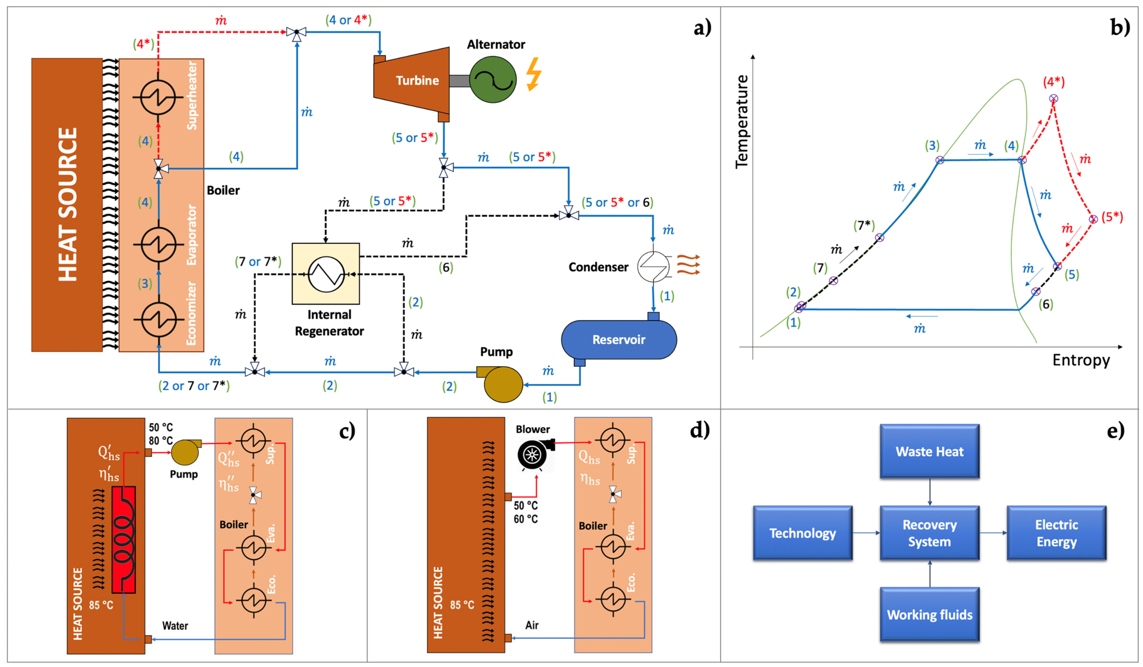
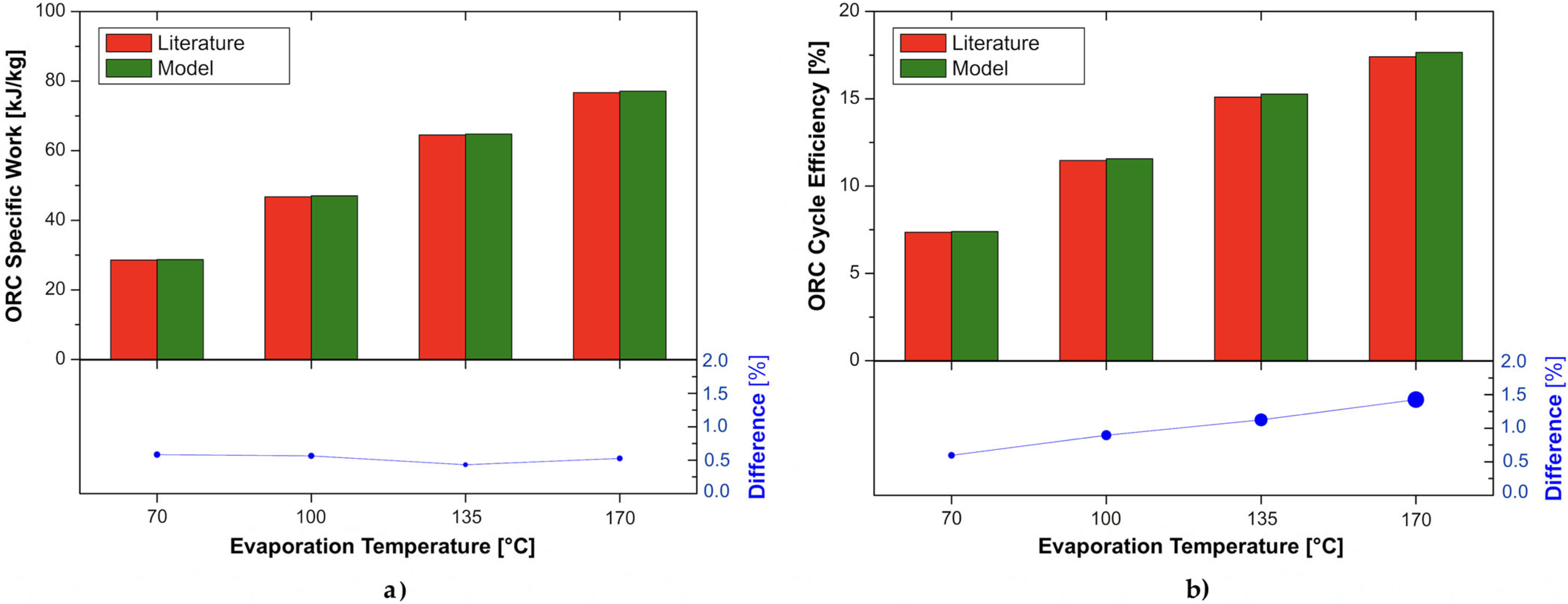
5. Waste Heat Recovery (WHR) Based on ORC Technologies

Compared to traditional steam power plants, ORC systems adopt organic fluids with higher molecular mass and lower boiling points as working fluids. The ORC units are suitable for small-scale applications, with electric power ranging between 1 kW and 10 MW. The main advantage of this technology lies in its ability to exploit low-temperature and waste heat from several sources, such as industrial processes [55,56], internal combustion engines [57,58], geothermal energy [59,60], solar energy [61,62], biomass [63,64], and, also, the waste heat generated by data centers [3,65]. The adoption of ORC for low-temperature WHR has many advantages, like simple mechanical structure, low pressure, convenient maintenance, and remarkable economic benefits [66,67].
The increasing interest in small-scale systems for WHR purposes, with time-variable conditions of the heat source and heat sink, raises the issue of off-design plant operation [68,69,70]. This area of low-temperature heat sources has been the subject of several comprehensive review papers that delve into a broad range of topics, from technical and energy-related issues to those focusing on the characteristics of the heat source and economic considerations [71,72,73,74,75].
Specifically, the study in [75] provides an in-depth review of WHR using ORC, examining various system designs discussed in the literature. The paper covers a variety of ORC configurations, including those used as bottoming cycles, in combined cycles, alongside heat pumps and multi-fluid systems, as well as real-world industrial applications. The conclusions drawn highlight ORC as both technically and economically feasible.
Typical ORC systems often encounter significant exergy losses in the evaporator due to a mismatch in temperature between the heat source and the working fluid [76,77,78]. Trilateral cycle (TLC) and organic flash cycle (OFC) variants are emerging as promising alternatives. These cycles offer improved performance and a better alignment of temperatures between the heat source and working fluid in the evaporator. However, both TLC and OFC are currently undergoing further technical refinement. The unique feature of TLC is its expansion process beginning at the boiling point while the fluid is still in a liquid state, leading to entry into the two-phase region and thus employing a two-phase turbo-expander. On the other hand, OFC represents a middle ground between TLC and the conventional ORC. In OFC, an initial expansion occurs at the boiling point in a two-phase state, followed by a division of the flow rate—one part is brought to saturated liquid conditions via an iso-thermobaric process and then expanded, while the other reaches saturated vapor conditions for subsequent expansion. This approach effectively lowers the latent-to-sensible heat ratio of the working fluid in the ORC heater, cooling the waste heat flux to lower temperatures more efficiently.
Furthermore, transcritical ORCs are noteworthy due to their superior efficiency over subcritical configurations [79,80]. The advantages of transcritical systems stem from their ability to offer significant reductions in size and facilitate more effective heat transfer from the heat source to the organic fluid [81,82]. This efficiency gain is mainly due to minimized irreversibility and reduced energy loss. Comparative analyses of optimized systems have shown that transcritical setups usually have shorter payback periods than subcritical ones across various working fluids, with reductions reaching up to 90%. For instance, a study detailed in the referenced work [81] conducts a techno-economic evaluation of an innovative CHP hybrid biomass/solar transcritical ORC system operating with a medium thermal oil at 350 °C, demonstrating notable efficiency even under partial load conditions. Similarly, another study examines the transcritical ORC system adoption to harness a high-temperature geothermal source at 230 °C [82].

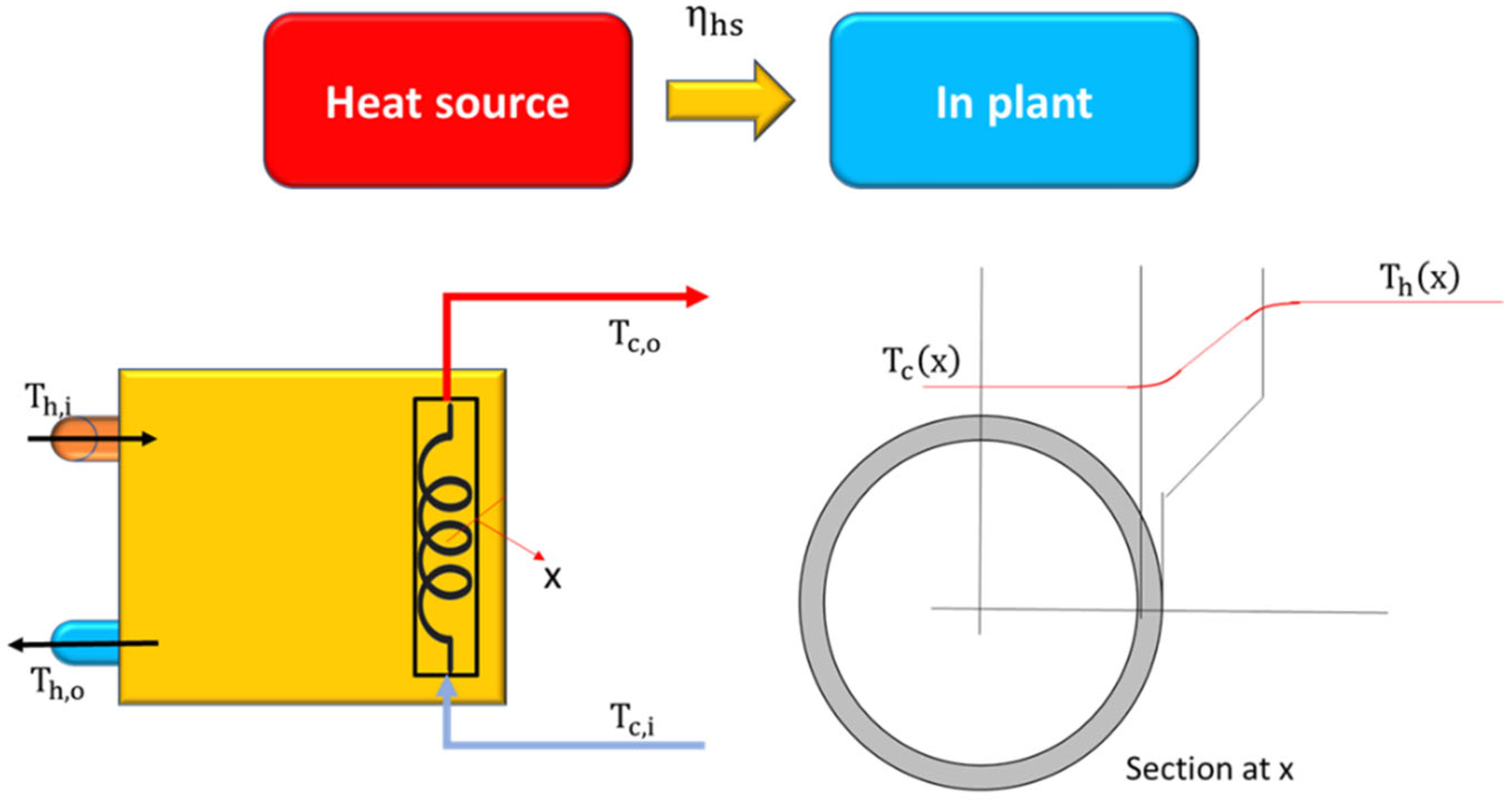
6. Plant Layout and Design Criterion

This segment explores the standard configuration of an energy system utilizing organic Rankine cycle architecture, designed to capitalize on waste heat. The foundational design principles refer to core thermodynamic and energy engineering rules generally shared in the literature [75,83,84]. Figure 2 illustrates various aspects of this design with the overall layout of the plant (a), the corresponding thermodynamic cycle (b), the indirect heat recovery (c), the direct heat recovery (d), and the schematic of the general configuration (e).
Figure 2a displays the system components and the potential engineered streams. The boiler, integral to producing vapor, receives heat from the primary source and consists of an economizer (2–3), evaporator (3–4), and superheater (4–4*). Accordingly, a pre-heating phase would be possible in the case of internal regeneration or when other thermal sources are available. A pump is responsible for circulating and increasing the pressure of working fluid. Saturated (point 4) or superheated (point 4*) conditions at the entrance of the turbine are possible depending on the adoption of the superheater. The system can integrate an internal regenerator to exploit the fluid energy content at the exit of the turbine (point 5 or 5*, with or without the superheater, respectively) and pre-heat the organic fluid (point 2) before the entrance to the boiler. A reservoir is typically used as a buffer tank [75]. Some authors even consider additional regenerative spills while expanding partial flow rates [85].
Figure 2b outlines the thermodynamic cycle and the fluid transformations. Figure 2c,d pertain to heat transfer from the heat source. Specifically, the indirect heat recovery (Figure 2c) generically illustrates the adoption of an intermediate thermal liquid (water) for heat transfer from the source to the ORC system [86]. A pump is required to circulate the fluid into the evaporator. Direct heat recovery (Figure 2d) involves using air directly from electronics cooling. In this case, an additional blower drives air into the ORC evaporator. The heat recovery assumes cooling fluid coming from high-temperature electronics (considering temperatures up to 85 °C of the microprocessors [12]), given the necessity of having high-quality heat for the ORC system. Consequently, for the proposed analysis, the air return temperature ranges between 50 and 60 °C (direct heat recovery), and the corresponding values for water are between 50 and 80 °C (indirect heat recovery), according to the literature [12]. The cooling techniques for the sake of system simplicity are one-phase. For illustration purposes, Figure 2c,d display the potential temperatures achievable at the various stages of the heat transfer process, from electronics to the ORC boiler.
It is important to emphasize that some enhancements, like regenerative pins, pose challenges in implementation. However, this discussion aims to provide a general framework of various strategies for cycle improvement. For smaller systems, adopting specific solutions can be particularly challenging due to a prevailing inclination toward simplifying plant designs. Moreover, even large-scale systems frequently result from the parallel assembly of smaller sub-modules. Thus, the configuration depicted in Figure 2b represents a broadly applicable model.
Figure 2e concludes with a scheme showing the path to generating electric energy from waste heat through a recovery plant, highlighting the choice of suitable energy technology and the appropriate working fluid. The following paragraphs will delve deeper into these aspects.
After presenting the potential system layouts, the design criteria are detailed. Fundamental design equations, such as that for energy conservation (1), are outlined. The Bernoulli-related equation plays a key role in modeling, linking the operating pressure with the pump head, and aiding in the design of fluid circulation (2).
Energy conservation
i m ˙ i   h i o m ˙ o   h o = m   c p   d T d t
Bernoulli equation
H m = z o z i + p o p i ρ   g + v o 2 v i 2 2   g + Y t o t
where m ˙ represents the mass flow rate, h is the enthalpy, m corresponds to the mass, c p is the specific heat, T is the temperature, and t is the time, while subscripts i and o refer to inlet and outlet sections, respectively. Furthermore, H m is the pump head, Y t o t represents the head losses, and z , p , and v are the fluid height, pressure, and velocity, respectively.
The heat transfer model is crucial when considering the heat source side, specifically for heat exchange from waste heat (3)–(5):
Heat transfer
Q ˙ k = U k   A k   T k = T k R k
R k = 1 h ¯ k i · A + L k λ k 1 · A ,   l n r e k 1 r i k 1 2 π L k · λ k 1 + + L k λ k n · A ,   l n r e k n r i k n 2 π L k n · λ k n + 1 h ¯ k e · A
U = 1 1 h ¯ i + L 1 λ 1 ,     l n r e 1 r i 1 · r a v e 1 + + L n λ n ,     l n r e n r i n · r a v e n + 1 h ¯ i e = 1 R t o t   A
where Q ˙ is the thermal power transferred through heat exchangers, U represents the thermal transmittance, A corresponds to the area, T is the temperature difference, R is the thermal resistance, h ¯ represents the convective heat transfer coefficient, λ k is the conductive heat transfer coefficient, and subscript k refers to the generic component.
Lastly, attention is on the saturation process. The saturation pressure and temperature depend on the characteristics of the heat source, particularly its supply temperature. The Antoine equation can be employed to calculate saturation, as detailed in (6). This equation articulates the correlation between the saturated vapor pressure ( p s ) and temperature ( T s ) for chemically pure liquids and their mixtures [87]:
Antoine equation
log 10 p s = a b / T s + c
where a , b , and c are coefficients depending on the fluid.
Energy analysis of the thermodynamic cycle
Table 2 summarizes the power involved in ORC system components, according to Figure 2.
Ultimately, the analysis culminates with efficiency evaluation at the cycle ( η c y c ) and system ( η s y s ) levels (20) and (21).
Energy performance of the cycle
η c y c = P t P p Q ˙ b o i l
Energy performance of the system
η s y s = P e l , t   P e l , p   P e l , a u x   Q ˙ h s
The subscript t refers to the turbine, p to the pump, b o i l to the boiler, h s to the heat source, a u x to the auxiliary equipment, and e l to the electric vector. Specifically, the electric power of the turbine and pump is calculated as follows:
P e l , t = η e l , t   η m , t   P t
P e l , p = P p   /   η e l , p   η m , p
and the heat source thermal power is
Q ˙ h s = Q b o i l   /   η h s  
where η e l is the electric efficiency, η m represents the mechanical efficiency, and η h s accounts for the heat transfer efficiency at the boiler.

7. Analysis of Working Fluids for Low-Temperature ORC
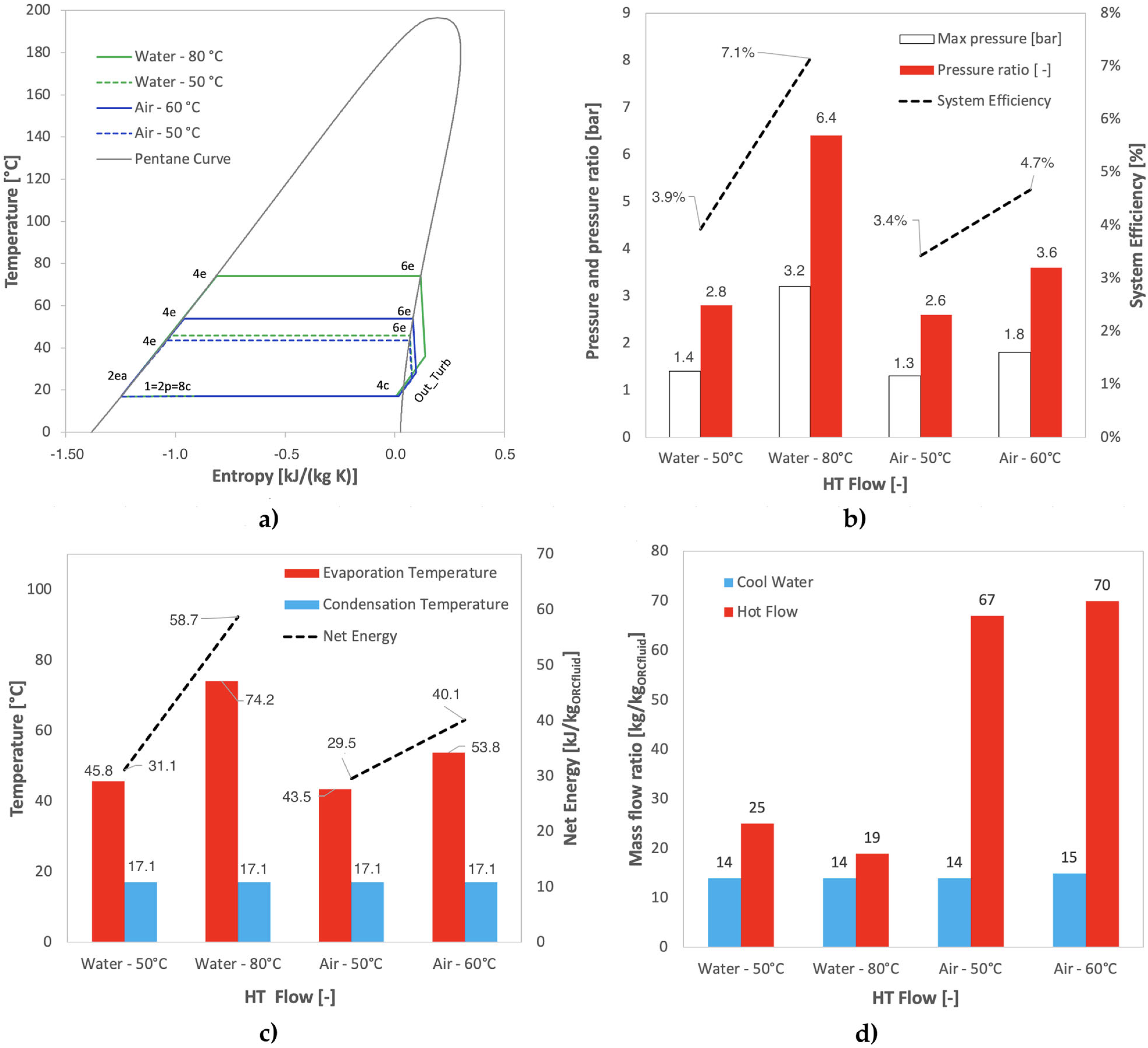
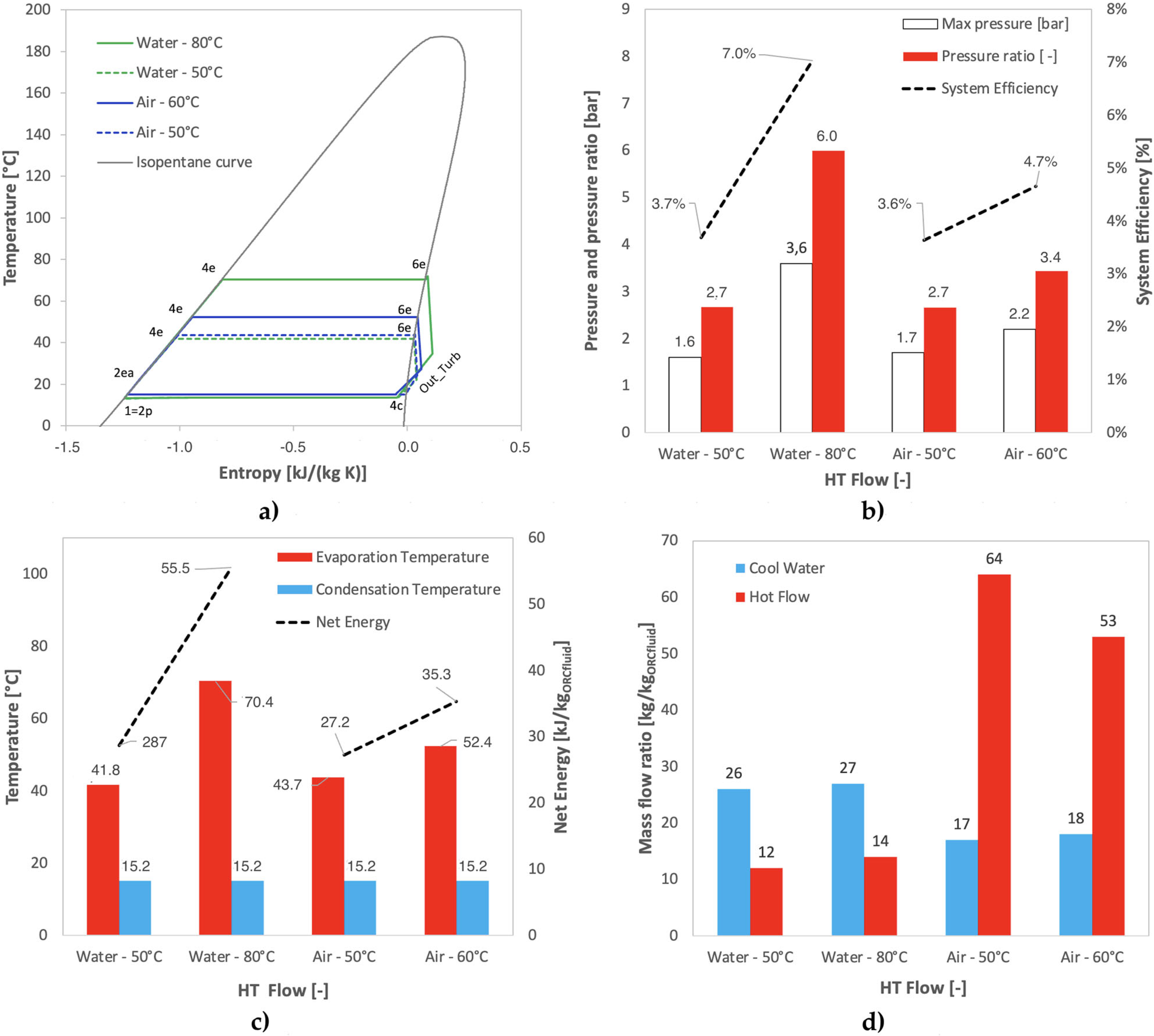
Selecting an appropriate working fluid is a critical aspect in the design of an energy recovery system based on an ORC architecture [88,89]. The design and evaluation of evaporation and condensation processes are crucial. Matching the critical temperature of the ORC fluid with the maximum temperature of the thermal source is essential, enabling the system to attain the maximum saturation pressure on the fluid. Similarly, managing condensation is essential to optimize the ORC energy performance.
A compilation of potential working fluids is provided to assist technical designers in this initial stage. Table 3 serves as a comprehensive database for these fluids, detailing parameters such as the recognition code, ozone depletion potential (ODP), and global warming potential (GWP), along with key thermophysical properties like molecular mass, boiling point, critical temperature and pressure, and latent heat of evaporation, according to the literature [90,91,92,93] and chemical databases. ODP indicates the potential negative impact on the ozone layer, with trichlorofluoromethane (R-11) as a benchmark (i.e., ODP = 1). On the other hand, GWP measures the greenhouse effect compared to carbon dioxide (CO2), which has a standard potential of 1.
As also anticipated, selecting the appropriate working fluid for a bottoming plant powered by WHR from data centers involves considering various critical factors. These include the fluid’s boiling point, critical temperature, environmental impact, and availability.
Usually, proper organic fluids present critical temperatures 25–35 °C lower than the source thermal level when the waste heat target temperature is unconstrained. Organic fluids with high critical temperatures represent the most suitable choice for constrained target temperatures.
However, it is impossible to define a single optimal ORC working fluid for specific thermal sources and applications, owing to the numerous available selection criteria and organic fluids [94]. The screening method is a popular approach for fluid selection but has limitations as it does not fully consider the practical design of the cycle. An alternative is the operating map approach, a pre-selection tool that considers the interaction between the expander, heat exchangers, and the working fluid to narrow down the possible choices.
The study reported below complements the data presented in Table 3 with a summary derived from recent literature, offering insights into the performance of ORC systems when integrated with low-grade WHR.
The study by [92] addresses the selection of working fluids for an ORC driven by refinery waste heat. The authors analyzed the performance of several substances of the R-type family. Fixing the condensation temperature at 45 °C, the R-fluids offered thermal efficiencies ranging between 7% and 17% at evaporation temperatures of 100–195 °C. The focus primarily rests on four candidates: R600a, R236ea, R227ea, and R601. When the target temperature of the waste heat source was higher than 120 °C, R601 appeared as the optimum working fluid. The findings indicated that R600a showed the highest thermal efficiency and maximum power output, and it recovered the entire waste heat under all evaporation temperatures. R236ea exhibited almost the same thermal efficiency as R600a while maintaining robust performance. Conversely, R227ea and R601 had higher thermal efficiency under a few conditions but generally performed less satisfactorily.
Herath et al. [93] analyze the behavior of ORC systems adopting several working fluids (e.g., benzene, acetone, propane, ethanol, and methanol, in addition to the conventional R-fluids, like R134a and R245fa). The results highlight thermal efficiency increases associated with evaporator pressure changes (globally 10–18.5% at 11–15 bar, spanning an evaporator temperature of 70–227 °C) and decreases with condensation temperature increase. In this study, benzene is selected as the best fluid, implying significantly improved efficiencies for several operating conditions compared to other ORC fluids. In [90], the performance of various organic working fluids in a geothermal ORC system is studied. Five fluids are used while evaluating thermal efficiency, pump power consumption, and the exergy efficiency of the system. The study concludes that R113 exhibits the best overall performance, while R245fa has a slight advantage over other fluids in terms of turbine power output. Considering the refrigerant, the study suggests that R600a has a superior ratio of area–system power, although the pump power required is significantly higher than other organic working fluids. A maximum system thermal efficiency of 5–5.5% is assessed at 100 °C, according to the fluids selected (R600a, R245fa, R141, R123, R113b).
The article in [86] discusses the experimental characterization of an ORC system for geothermal energy conversion. The system consists of a recuperative ORC equipped with a scroll expander and a direct contact evaporator (water/organic fluid) with counter-current gas/water heat exchange. The heat source temperature range was 65–85 °C, while the operating pressure was 10.9–16.8 bar. The experimental results showed that the tested system can operate with 5% efficiency using R123. The paper by [95] presents a simulation study on an ORC system with four different working fluids, namely R134a, R32, R407a, and R422c, to determine the thermal efficiency of the system in various temperature setups of the evaporator and condenser. The study assumes a mass flow rate of 0.15 kg/s. The results show that the optimum and realistic efficiency is achieved using R32 with a thermal efficiency of 7.0% at the evaporator exit temperature of 75 °C and condenser exit temperature of 45 °C. The higher efficiency obtained using R407a and R422c seems to be uncompromised.
Pasinato [91] aims to assess the thermodynamic performance of 20 working fluids for an ORC. The investigation evaluates the fluids based on several technical criteria, such as critical temperature, boiling point, and heat transfer coefficient. The results show that the choice of working fluid significantly impacts the ORC performance and that the most influencing parameter for assessing fluid performance is the critical temperature. The study concludes that R245fa, R245ca, R123, R141b, and benzene, in that order, are the best-performing fluids for a temperature range of 197–380 °C.
Dai et al. [96] review the thermal stability of several working fluids and discuss three methods for measuring thermal stability: differential scanning calorimetry (DSC), pressure changes, and rapid experimental methods. The results reveal that the thermal stability of working fluids mainly depends on their chemical properties, not their physical properties. R245fa and R1336mzz-Z are recommended as working fluids with good thermal stability. The study by [97] applies the technique for order preference by similarity to an ideal solution to determine properties. The Pearson correlation coefficient (R) is calculated to identify the statistical relation between the physical properties. The investigation illustrates pentane as a clean and thermally superior fluid, followed by butane, cyclopropane, and isobutane. However, chlorofluorocarbons (CFCs) and hydrofluorocarbons (HFCs) acquire good ranks but pose serious environmental threats. The study also concludes that a combination of thermal and environmental properties is necessary for selecting suitable organic fluids for ORC.
The study by [98] explores the choice of suitable working fluids through exergy–economic analyses, considering a heat source temperature of 120 °C and a pressure ratio of approximately 3. Objective functions for system optimization include exergy efficiency and the cost rate of electricity, evaluating each fluid based on optimal operating conditions. Exergy efficiency ranges from 15% to 22%, while thermal efficiency ranges from 4.4% to 6.2%. R134a and isobutane demonstrate the highest exergy efficiencies and represent the most appropriate working fluids for investigated ORC systems. The methodology entails simulating the thermodynamic performance of a regenerative ORC that harnesses low-temperature heat sources. The results indicate that the optimal working fluid for ORC, considering parameters such as expander size, system efficiency, and pressure, lies between R290 and R134a or R600a.

8. Application Case

This paragraph aims to complete the analysis by presenting an application case for an ORC energy system using the waste heat deriving from data center cooling as a heat source. For this purpose, modeling is carried out in the DWSIM environment. The system is scrupulously designed through a series of iterative tests, calibrating, if necessary, the heating flows, responsible for the evaporation of the organic fluid, and the cooling flows, responsible for condensation. The model defines the minimum flow rates required to establish the energy cycle.
The evaporation and condensation processes of the ORC fluid are delicate, as already known. The critical aspects concern (1) the ability to evaporate the fluid with hot air or liquid at the available temperatures and (2) the ability to condense with available natural resources such as ambient water. Therefore, the limit temperatures depend on the waste heat level of the data centers and water from the distribution circuit or any available well. Within these boundaries, each organic fluid responds as a function of its thermophysical capabilities, i.e., a more or less high maximum evaporation pressure and a more or less low condensation pressure, which imposes the condensation temperature.
Preliminary model validation has been performed with literature data [99] referring to ORC systems to harness geothermal sources in Southern Italy. The same subcritical regenerative configuration is recreated in the DWSIM computational environment, using isopentane as the working fluid and maintaining consistent operating conditions. The analysis illustrates that the proposed model well characterizes the ORC performance. As an example, Figure 3 compares literature data and model results in terms of specific work (Figure 3a) and thermal efficiency (Figure 3b) as a function of the evaporation temperature. The percentage differences range between 0.6% and 1.4% for all the investigated conditions and parameters, indicating the accuracy of the proposed ORC model. This validation process serves as a demonstrated robust tool for conducting simulations.
Based on the preparatory analyses conducted, it is plausible to consider a data center with an average power density of at least 10 kW/m2. Two flow streams provide heat to the ORC system. One flow is pertinent to the ultra-low temperature of air (LT-AIR), tasked with cooling the data center rooms, characterized by an outlet temperature of approximately 30 °C, to pre-heat the ORC organic fluid. The second flow at high temperature (HT-FLOW) is responsible for the evaporation.
For this purpose, the investigations consider a scenario involving forced air and another with liquid water. Specifically, the liquid water is assumed to return from the conditioning unit with temperatures ranging between 50 and 80 °C [12,31]. On the other hand, the forced air presents an output temperature range of 50–60 °C [12,31] (Table 4).
In envisioning the system design, ducts leading from the pumped hot water and air blower to the heat exchanger represent a feasible approach (then acting as the heat source for the organic Rankine energy system). The ORC plant is engineered as depicted in Figure 4. It responds to the Rankine scheme, including the pre-heating and evaporation section, the condensation part, the pump for fluid pressurization and circulation, and the expander dedicated to energy generation while reducing and bringing the pressure back to the initial level.
The heat provision is attributed to the chain of heat exchanger PRE-HEAT/ECO/EVA/SUP-HEAT, where the pre-heating of the ORC fluid and its evaporation occurs, while the cooling and condensation processes take place in the chain DE-SH/COND/L-COOL. Ambient water is used for condensation.
Table 4 includes the calculation setting of the ORC system. As previously mentioned, primary heat source temperatures range between 50 and 80 °C when using water and between 50 °C and 60 °C when using air. An additional air mass flow rate at 30 °C is for pre-heating purposes.
The condensing water is at an underground temperature of 10 °C. The ORC system operates with a 1 kg/s mass flow rate, and iterative tests define the upper and lower pressure limits. This procedure also applies to the air-evaporating and water-condensing mass flow rates.
Given the broad range of ORC working fluids suitable for low temperatures, the selection narrows significantly under imposed temperature limits, such as the evaporation temperature, which needs to align with the thermal resource, and the condensation temperature, which needs to be compatible with the cold-water resource.
With these constraints, the focus has shifted towards pentane and isopentane as working fluids. The selection of these fluids is guided by insights from the reference literature, highlighting their suitability for efficient low-grade waste heat recovery [1,100,101] and low environmental impact [74,102]. The corresponding zero ozone depletion potential (ODP) and low global warming potential (GWP) represent fundamental factors in promoting the transition toward clean data centers.
Based on the previous configurations, simulations are conducted in the DWSIM computational environment. The focus is on calculating a comprehensive set of thermodynamic parameters, including pressure, temperature, mass density, enthalpy, entropy, and the fractions of liquid and vapor, as well as energy parameters such as input and output power. Figure 5 displays the results for the ORC system using pentane as the working fluid, whereas Figure 6 pertains to isopentane. Each figure consists of the thermodynamic cycle (a), a chart presenting pressures, pressure ratios, and system efficiency (b), a chart reporting evaporation and condensation temperatures and net energy (c), the mass ratios between the heat source and the ORC fluids, and the condensation water and the ORC fluids (d).
For pentane, the evaporation temperatures achieved are 45.8 °C and 74.2 °C, corresponding to hot liquid water temperatures of 50 and 80 °C, respectively. Evaporation temperatures of 43.5 °C and 53.8 °C are registered using hot air at 50 °C and 60 °C. The condensation temperature is 17.1 °C for all cases. The maximum saturation pressures that the system can handle limit these temperatures. This detail is in Figure 5b, where tests have determined the maximum evaporation pressure to be 1.4 bar and 3.2 bar for water and 1.3 bar and 1.8 bar for air. These values are associated with pressure ratios of 2.8–6.4 (adopting hot water) and 2.6–3.6 (adopting hot air), respectively, which have a lower limit associated with the minimum temperature of the natural water, which, in turn, determines the condensation pressure. Consequently, the net electric efficiencies at the system level are 3.9% and 7.1% (for water), and 3.4% and 4.7% (for air), respectively.
The net electric energy delivery ranges from 31.1 kJ/kg to 58.7 kJ/kg, with hot water as a heat source, and moves from 29.5 kJ/kg to 40.1 kJ/kg using air (Figure 5c). The final chart (Figure 5d) shows that to evaporate 1 kg/s of pentane, a mass flow rate of 25 and 19 kg/s is necessary using hot liquid water, while 67–70 kg/s is required using hot air. Similarly, the temperature range of cold water derived for ORC condensation is about 14–15 kg/s.
The same considerations apply to isopentane as the working fluid, with results detailed in Figure 6. Without delving into the specifics, the net electric efficiency at the system level ranges from 3.7% in the worst case to 7.0% in the best case. The pressure ratios vary from 2.7 to 6.0, with a maximum operating pressure of 3.6 bar. The results align closely with the existing literature. The efficiency also accounts for the auxiliary power due to the water pump.

9. Discussion

The previous analysis demonstrated that ORC systems driven by hot water offer higher efficiency than air-based systems and require lower flow rate input and size for the primary heat exchanger to evaporate the organic fluid.
It is important to note that the temperatures of heat and cold sources significantly influence the ORC operating conditions. For example, if alternative cold sources were available, the condensation pressure could be significantly reduced, thereby expanding the pressure ratio and the operational range of the turbo-expander. A practical instance might include facilities that manage cold sources, such as those using refrigerants for food preservation or medical centers and hospitals equipped with cryogenic fluids like liquid nitrogen [103]. While this is just an example, it aptly demonstrates the potential for energy and mass waste recovery, contributing to the waste-to-energy chain and the circular energy economy, as well as clean energy production and decarbonization. Nonetheless, a comprehensive system feasibility assessment must consider economic factors. This study focuses on outlining the purely technical and energetic aspects, aiming to engineer a system that is as realistic as possible.
The design approach outlined in this paper aligns with standard energy consumption metrics commonly used in data centers [104,105]. For this purpose, the power usage effectiveness (PUE), the energy reuse effectiveness (ERE), and the energy reuse factor are adopted to evaluate the energy performance of data centers and the possible benefits of DC heat exploitation through the proposed ORC systems.
The power usage effectiveness is as follows [105,106]:
P U E = P I T + P C   + P A P I T
where P I T is the power consumption of the information technology (IT) system, P A represents the power request of the auxiliary equipment (e.g., uninterrupted power supply units, highlighting system, control devices), and P C is the power demand of the cooling apparatus.
The energy reuse factor and the energy reuse effectiveness are as follows [104,107,108]:
E R F = P r P I T + P C   + P A = P O R C P I T + P C   + P A
E R E = P I T + P C   + P A P r P I T = P U E   1 E R F
where P r is the power reuse, equivalent to the ORC electric power for the investigated case.
The analysis considers a reference data center, whose main characteristics are in Table 5 [109], as a possible example of DC heat reuse based on the results of the previous sections. However, the main results can extend to similar configurations with different sizes. The reference data center presents a total area for IT rooms equal to about 5700 m2, with a total power for IT equipment and auxiliary systems equal to 12.9 MW and 0.97 MW, respectively. The power usage effectiveness corresponds to 1.295.
The data center heat exploitation assures an ORC installation with 665 kW as the maximum electric power at 3.7% electric efficiency, adopting isopentane as the working fluid, 41.7 °C as the evaporation temperature, and liquid cooling for the DC apparatus. The ERF index is 0.041, illustrating that the ORC electric power corresponds to 4.1% of the total DC power request for IT equipment, auxiliary systems, and cooling apparatus. The proposed organic Rankine cycle assures an energy reuse effectiveness equal to 1.242, compared to a PUE equal to 1.295 in the reference scenario without DC heat reuse, in line with the literature [110].
The ORC integration assures a yearly 5972 MWh electric generation and saves 3328 tons of equivalent carbon dioxide (tCO2,eq) in terms of greenhouse gas (GHG) emissions, adopting the 2023 emission factors for electric generation in China [111]. The GHG saving associated with the data center electric request is 22.7 kgCO2,eq/MWh, demonstrating the significant potential to reduce emissions and promote a sustainable transition towards a greener future, considering the expected continuous increase in data center electric consumption in the next few years.

Guidelines for Further Analysis and Dimensioning

This section accompanies the calculations by offering a guide for a thorough analysis, including exergy considerations. It also outlines the steps for designing the evaporator and condenser.
Exergy analysis is pivotal when assessing and selecting an appropriate working fluid, where the most favorable choice presents minimal exergy destruction during the heat transfer process. The practical dimensioning includes the determination of the mass flow rate of the working fluid and the corresponding sizing of the heat exchangers.
The exergy analysis is detailed in expressions (28) and (29), incorporating exergy contributions such as physical, chemical, potential, and kinetic. The exergy balance is then outlined in expression (29), encompassing the exergies at the inlet ( E ˙ i ) and outlet ( E ˙ o ), as well as the thermal exergy at the inlet ( E ˙ Q ), the exergy contributing to the net useful power ( L ˙ N ), and the exergy destruction ( E ˙ d e s ). Equations (30) and (31) calculate the thermal exergy and exergy destruction, while Equations (32) and (33) regard the exergy efficiency ( ψ ) and exergy defect ( δ i ).
Exergy analysis
E ˙ k = E ˙ p h + E ˙ c h + E ˙ p o + E ˙ k i
E ˙ i + E ˙ Q = E ˙ o + L ˙ N + E ˙ d e s
E ˙ Q = k = 1 n Q ˙ k · 1 T 0 T k
E ˙ d e s = T 0 · o = 1 n m ˙ o · s ¯ o i = 1 n m ˙ i · s ¯ i k = 1 n Q ˙ k T k
ψ = 1 δ k
δ k = E ˙ d e s , k Δ E ˙ i n
The sizing of the heat exchangers further complements the analysis. Figure 7 schematically displays the transfer from the waste heat source to the ORC.
Expression (34) determines the mass flow rate of the hot fluid ( m ˙ h ) resulting from the DC cooling process required in the ORC system with 1 kg/s of the working fluid ( m ˙ ). Following the principles of thermal engineering, the size ( l e v a ) of the evaporator is calculated per mass flow rate of the hot fluid, as in (35).
Similarly, the principles apply to sizing the condenser. Equations (36) and (37) are used to calculate the mass flow rate of the cold fluid ( m ˙ c ) for condensation (relative to 1 kg/s of the working fluid) and the size ( l c o n d ) of the evaporator (per mass flow rate of the cold fluid), respectively.
Evaporator sizing (per kg of hot fluid)
m ˙ h m ˙ = h o , b o i l h i , b o i l η h s   c p , h   T h , i T h , o
l e v a m ˙ h = η h s   c p , h   T h , i T h , o U e v a   π   d   T l n    
Condenser sizing (per kg of cold fluid)
m ˙ c m ˙ = h i , c o n d h o , c o n d η h s   c p , c   T c , o T c , i
l c o n d m ˙ c = η h s   c p , c   T c , o T c , i U c o n d   π · d   T l n    

10. Conclusions

This paper provided a detailed framework for the energy exploitation of the low-grade waste heat of data centers, considering their typical operating conditions and energy streams, adopting ORC systems for electrical energy to promote an efficient transition towards a more sustainable future.
Estimates suggest that power consumption in data centers ranges from 15 to 20 kW/m2, potentially reaching as high as 96 kW/m2 in specific instances. The resulting thermal output is considerable, as electronics tend to heat up, making cooling an essential aspect of their operation. The literature suggests that about 50% of the heat from cooling electronic equipment can be exploited (and, in some cases, more than 70%). The discussion covered various cooling strategies, including air, liquid, and two-phase fluid-based systems, and their efficiency in thermal waste management. Air cooling systems, favored for their related simplicity, represent approximately 70% of the cooling methods employed. Water cooling has demonstrated greater effectiveness, enabling significant reductions in cooling flow rates, albeit less commonly adopted compared to air cooling solutions. The waste heat from data centers typically manifests as warm air or hot liquid water. Concerning air-based cooling, roughly 80% of the heat is at temperatures around 30 °C, related to overall air flow, including within rooms, while the rest ranges from 50 to 60 °C, stemming from the cooling of high-heat equipment. A corresponding temperature within a 50–80 °C range is typical for liquid water.
The investigation thus supported the adoption of ORC technology as a viable method for generating electricity from low-grade heat. The findings indicated that electric efficiencies higher than 5% are attainable in data centers by employing ORC systems with low-boiling fluids.
A crucial focus of this study was the analysis and selection of working fluids, highlighting that there is no universally optimal fluid for any specific temperature range or application due to the potentially vast array of fluids and the varying criteria for selection. The key challenges encountered depend on the maximum and minimum operating pressures. These concerns are related to (1) the capability to vaporize the fluid using the available thermal source temperatures and (2) the capacity to achieve condensation with naturally available resources, such as ambient water.
This paper proposed a standardized structure for an energy system, outlining the components and their functions. For this purpose, an organic Rankine cycle was analyzed, including fluid streams for internal operations. The design and sizing criteria were detailed, starting from the thermodynamic analysis to continuing with the energy performance investigation of the entire system.
An application case completed this study using the DWSIM computational environment. Warm air and hot liquid water were considered for the primary heat source at the potential temperatures of 50–60 °C and 50–80 °C, respectively. A secondary air mass flow at 30 °C complemented the pre-heating section. The condensation process utilized underground water at a temperature equal to 10 °C. Given the specific temperature requirements for evaporation and condensation to match the thermal and cold-water resources, respectively, pentane and isopentane were identified as suitable working fluids. For the pentane ORC system, operating pressure ratios of 2.6 and 6.4 led to net electric efficiencies of 3.4% and 7.1% at the plant level, respectively. Meanwhile, the isopentane system achieved net electric efficiencies ranging from 3.6% to 7.0% at operating pressure ratios from 2.7 to 6.0. The most favorable results were obtained when utilizing liquid water as the heat source.
The investigation highlights that the ORC integration provides noteworthy energy and environmental performance improvements for data centers. For the investigated DC, the exploitation of the heat waste through the proposed ORC guarantees an electric production corresponding to 4.1% of the DC total electric request and 22.7 kgCO2,eq GHG emission savings per MWh of electric consumption.
This research concluded by offering guidelines for analyzing ORC systems, including exergy analysis, and detailing the process of sizing the evaporator and condenser. A forthcoming investigation will focus on energy process optimization by exploring various system layouts, enhancing heat exchange mechanisms, and considering alternative operating conditions and working fluids.

Author Contributions

Conceptualization, O.C., A.A., and P.F.; methodology, O.C., A.A., and P.F.; software, O.C.; validation, O.C., A.A., and P.F.; formal analysis, O.C., A.A., and P.F.; investigation, O.C. and A.A.; resources, P.F.; data curation, O.C.; writing—original draft preparation, O.C., A.A., and P.F.; writing—review and editing, O.C., A.A., and P.F.; visualization, O.C., A.A., and P.F.; supervision, A.A. and P.F.; project administration, P.F. All authors have read and agreed to the published version of the manuscript.

Funding

This research received no external funding.

Institutional Review Board Statement

Not applicable.

Informed Consent Statement

Not applicable.

Data Availability Statement

The raw data supporting the conclusions of this article will be made available by the authors on request.

Conflicts of Interest

The authors declare no conflicts of interest.

Nomenclature

Acronyms and tags
AIArtificial intelligence
CCHPCombined cooling, heating, and power
CFCChlorofluorocarbons
CHPCombined heating and power
CONDCondenser
COPCoefficient of performance
CRACComputer room air conditioning
DCData center
DE-SHDesuperheater
DSCDifferential scanning calorimetry
ECOEconomizer
EEDEnergy Efficiency Directive
EREEnergy reuse effectiveness
ERFEnergy reuse factor
EVAEvaporator
GHGGreenhouse gas
GWPGlobal warming potential
HFCHydrofluorocarbons
HT-FLOWHigh-temperature flow
HVACHeating, ventilation, and air conditioning
ICTInformation and communication technology
IEAInternational Energy Agency
ITInformation technology
IUSIndustry and urban symbiosis
L-COOLCooler in the liquid phase for ORC
LT-AIRLow-temperature air
KPIKey performance indicators
NPVNet present value
ODPOzone depletion potential
ORCOrganic Rankine cycle
PRE-HEATPre-heater
PUEPower usage effectiveness
PUMP-ORCORC pump
PUMP-WAWater pump
SUP-HEATSuperheater
TURBO-EXPTurbo-expander
TLCTrilateral cycle
WHRWaste heat recovery
Symbols
A Area (m2)
aCoefficient (-)
bCoefficient (-)
cCoefficient (-)
cpSpecific heat (kJ/kgK)
dDiameter (m)
EExergy (W)
hSpecific enthalpy (kJ/kg)
hConvective heat transfer coefficient (W/m2K)
HmPump head (m)
LWidth (m)
lLength (m)
mMass (kg)
mMass flow rate (kg/s)
PPower (W)
pPressure (Pa)
QThermal power (W)
RThermal resistance (m2 K/W)
rRadius (m)
TTemperature (°C)
tTime (s)
UThermal transmittance (W/m2K)
vVelocity (m/s)
YtotHead losses (m)
zHeight (m), pressure, and velocity, respectively.
Greek symbols
ΔDifference
δExergy defect (-)
λConductive heat transfer coefficient (W/mK)
ΨExergy efficiency (-)
ηEfficiency (-)
Subscripts
auxAuxiliaries
boilBoiler
cCold
condCondenser
chChemical
cycCycle
desDestruction
elElectric
h Hot
h sHeat source
h ydHydraulic
iInlet
kGeneric component
kiKinetic
lnMean logarithmic
mMechanical
oOutlet
pPump
poPotential
phPhysical
QThermal
regRegenerator
sSaturation
sysSystem
tTurbine
0Standard

References

  1. Yuan, X.; Liang, Y.; Hu, X.; Xu, Y.; Chen, Y.; Kosonen, R. Waste Heat Recoveries in Data Centers: A Review. Renew. Sustain. Energy Rev. 2023, 188, 113777. [Google Scholar] [CrossRef]
  2. Jouhara, H.; Khordehgah, N.; Almahmoud, S.; Delpech, B.; Chauhan, A.; Tassou, S.A. Waste Heat Recovery Technologies and Applications. Therm. Sci. Eng. Prog. 2018, 6, 268–289. [Google Scholar] [CrossRef]
  3. Ancona, M.A.; Bianchi, M.; Branchini, L.; Pascale, A.D.; Melino, F.; Ottaviano, S.; Peretto, A.; Poletto, C. Experimental and Numerical Investigation of a Micro-ORC System for Heat Recovery from Data Centers. J. Phys. Conf. Ser. 2022, 2385, 012122. [Google Scholar] [CrossRef]
  4. Braimakis, K.; Karellas, S. Exergy Efficiency Potential of Dual-Phase Expansion Trilateral and Partial Evaporation ORC with Zeotropic Mixtures. Energy 2023, 262, 125475. [Google Scholar] [CrossRef]
  5. Pereira, J.S.; Ribeiro, J.B.; Mendes, R.; Vaz, G.C.; André, J.C. ORC Based Micro-Cogeneration Systems for Residential Application—A State of the Art Review and Current Challenges. Renew. Sustain. Energy Rev. 2018, 92, 728–743. [Google Scholar] [CrossRef]
  6. European Parliament and Council. Directive (EU) 2023/1791 of the European Parliament and of the Council of 13 September 2023 on Energy Efficiency and Amending Regulation (EU) 2023/955 (Recast). Off. J. Eur. Union 2023, L 231, 1–111. [Google Scholar]
  7. International Energy Agency (IEA). Data Centres and Data Transmission Networks. Available online: https://www.iea.org/energy-system/buildings/data-centres-and-data-transmission-networks (accessed on 16 April 2024).
  8. Jin, C.; Bai, X.; Yang, C.; Mao, W.; Xu, X. A Review of Power Consumption Models of Servers in Data Centers. Appl. Energy 2020, 265, 114806. [Google Scholar] [CrossRef]
  9. Rasmussen, N. Guidelines for Specification of Data Center Power Density; White Paper; 2015. Available online: https://www.se.com/id/en/download/document/SPD_NRAN-69ANM9_EN/ (accessed on 15 April 2024).
  10. Ahmed, K.M.U.; Bollen, M.H.J.; Alvarez, M. A Review of Data Centers Energy Consumption and Reliability Modeling. IEEE Access 2021, 9, 152536–152563. [Google Scholar] [CrossRef]
  11. Zhang, Y.; Liu, J. Prediction of Overall Energy Consumption of Data Centers in Different Locations. Sensors 2022, 22, 3704. [Google Scholar] [CrossRef]
  12. Ebrahimi, K.; Jones, G.F.; Fleischer, A.S. A Review of Data Center Cooling Technology, Operating Conditions and the Corresponding Low-Grade Waste Heat Recovery Opportunities. Renew. Sustain. Energy Rev. 2014, 31, 622–638. [Google Scholar] [CrossRef]
  13. Oltmanns, J.; Sauerwein, D.; Dammel, F.; Stephan, P.; Kuhn, C. Potential for Waste Heat Utilization of Hot-water-cooled Data Centers: A Case Study. Energy Sci. Eng. 2020, 8, 1793–1810. [Google Scholar] [CrossRef]
  14. Huang, P.; Copertaro, B.; Zhang, X.; Shen, J.; Löfgren, I.; Rönnelid, M.; Fahlen, J.; Andersson, D.; Svanfeldt, M. A Review of Data Centers as Prosumers in District Energy Systems: Renewable Energy Integration and Waste Heat Reuse for District Heating. Appl. Energy 2020, 258, 114109. [Google Scholar] [CrossRef]
  15. Zhang, Y.; Shan, K.; Li, X.; Li, H.; Wang, S. Research and Technologies for Next-Generation High-Temperature Data Centers—State-of-the-Arts and Future Perspectives. Renew. Sustain. Energy Rev. 2023, 171, 112991. [Google Scholar] [CrossRef]
  16. Dayarathna, M.; Wen, Y.; Fan, R. Data Center Energy Consumption Modeling: A Survey. IEEE Commun. Surv. Tutor. 2016, 18, 732–794. [Google Scholar] [CrossRef]
  17. Wahlroos, M.; Pärssinen, M.; Rinne, S.; Syri, S.; Manner, J. Future Views on Waste Heat Utilization—Case of Data Centers in Northern Europe. Renew. Sustain. Energy Rev. 2018, 82, 1749–1764. [Google Scholar] [CrossRef]
  18. Katal, A.; Dahiya, S.; Choudhury, T. Energy Efficiency in Cloud Computing Data Centers: A Survey on Software Technologies. Clust. Comput. 2023, 26, 1845–1875. [Google Scholar] [CrossRef] [PubMed]
  19. Yari, M.; Mehr, A.S.; Zare, V.; Mahmoudi, S.M.S.; Rosen, M.A. Exergoeconomic Comparison of TLC (Trilateral Rankine Cycle), ORC (Organic Rankine Cycle) and Kalina Cycle Using a Low Grade Heat Source. Energy 2015, 83, 712–722. [Google Scholar] [CrossRef]
  20. Mazhar, A.R.; Shen, Y.; Liu, S. Viability of Low-grade Heat Conversion Using Liquid Piston Stirling Engines. Wiley Interdiscip. Rev. Energy Environ. 2024, 13, e509. [Google Scholar] [CrossRef]
  21. Lottmann, M.; De Rouyan, Z.; Hasanovich, L.; Middleton, S.; Nicol-Seto, M.; Speer, C.; Nobes, D. Development of a 100-Watt-Scale Beta-Type Low Temperature Difference Stirling Engine Prototype. E3S Web Conf. 2021, 313, 08004. [Google Scholar] [CrossRef]
  22. Huang, H.; Chen, W. Development of a Compact Simple Unpressurized Watt-level Low-temperature-differential Stirling Engine. Int. J. Energy Res. 2020, 44, 12029–12044. [Google Scholar] [CrossRef]
  23. Wang, K.; Sanders, S.R.; Dubey, S.; Choo, F.H.; Duan, F. Stirling Cycle Engines for Recovering Low and Moderate Temperature Heat: A Review. Renew. Sustain. Energy Rev. 2016, 62, 89–108. [Google Scholar] [CrossRef]
  24. Research Institute of Sweden (RISE). Energy Use in Data Centers and Digital Systems; RISE Report 2023: 36; RISE Research Institutes of Sweden: Gothenburg, Sweden, 2023; p. 55. [Google Scholar]
  25. Vesterlund, M.; Borisová, S.; Emilsson, E. Data Center Excess Heat for Mealworm Farming, an Applied Analysis for Sustainable Protein Production. Appl. Energy 2024, 353, 121990. [Google Scholar] [CrossRef]
  26. Brännvall, R.; Mattson, L.; Lundmark, E.; Vesterlund, M. Data Center Excess Heat Recovery: A Case Study of Apple Drying. In Proceedings of the 33rd International Conference on Efficiency, Cost, Optimization, Simulation and Enviromental Impact of Energy Systems, Osaka, Japan, 29 June–3 July 2020; pp. 2165–2174. [Google Scholar]
  27. Yakovlev, I.V.; Avdokunin, N.V. Efficient Use of Waste Heat from Data Centers. Therm. Eng. 2023, 70, 769–776. [Google Scholar] [CrossRef]
  28. Pärssinen, M.; Wahlroos, M.; Manner, J.; Syri, S. Waste Heat from Data Centers: An Investment Analysis. Sustain. Cities Soc. 2019, 44, 428–444. [Google Scholar] [CrossRef]
  29. Zhang, C.; Luo, H.; Wang, Z. An Economic Analysis of Waste Heat Recovery and Utilization in Data Centers Considering Environmental Benefits. Sustain. Prod. Consum. 2022, 31, 127–138. [Google Scholar] [CrossRef]
  30. Araya, S.; Wemhoff, A.P.; Jones, G.F.; Fleischer, A.S. Study of a Lab-Scale Organic Rankine Cycle for the Ultra-Low-Temperature Waste Heat Recovery Associated With Data Centers. J. Electron. Packag. 2021, 143, 021001. [Google Scholar] [CrossRef]
  31. Ebrahimi, K.; Jones, G.F.; Fleischer, A.S. The Viability of Ultra Low Temperature Waste Heat Recovery Using Organic Rankine Cycle in Dual Loop Data Center Applications. Appl. Therm. Eng. 2017, 126, 393–406. [Google Scholar] [CrossRef]
  32. Chen, X.; Pan, M.; Li, X.; Zhang, K. Multi-Mode Operation and Thermo-Economic Analyses of Combined Cooling and Power Systems for Recovering Waste Heat from Data Centers. Energy Convers. Manag. 2022, 266, 115820. [Google Scholar] [CrossRef]
  33. Kanbur, B.B.; Wu, C.; Duan, F. Combined Heat and Power Generation via Hybrid Data Center Cooling-polymer Electrolyte Membrane Fuel Cell System. Int. J. Energy Res. 2020, 44, 4759–4772. [Google Scholar] [CrossRef]
  34. Yin, X.; Ye, C.; Ding, Y.; Song, Y. Exploiting Internet Data Centers as Energy Prosumers in Integrated Electricity-Heat System. IEEE Trans. Smart Grid 2023, 14, 167–182. [Google Scholar] [CrossRef]
  35. Wan, J.; Zhou, J.; Gui, X. Sustainability Analysis of Green Data Centers With CCHP and Waste Heat Reuse Systems. IEEE Trans. Sustain. Comput. 2021, 6, 155–167. [Google Scholar] [CrossRef]
  36. Medeiros, D. DWSIM. 2021. Available online: https://dwsim.org (accessed on 15 March 2024).
  37. Koomey, J.G. Growth in Data Center Electricity Use 2005 to 2010; Analytics Press: Oakland, CA, USA, 2011. [Google Scholar]
  38. Little, A.B.; Garimella, S. Waste Heat Recovery in Data Centers Using Sorption Systems. J. Therm. Sci. Eng. Appl. 2012, 4, 021007. [Google Scholar] [CrossRef]
  39. Abbas, A.M.; Huzayyin, A.S.; Mouneer, T.A.; Nada, S.A. Effect of Data Center Servers’ Power Density on the Decision of Using in-Row Cooling or Perimeter Cooling. Alex. Eng. J. 2021, 60, 3855–3867. [Google Scholar] [CrossRef]
  40. Balaras, C.A.; Lelekis, J.; Dascalaki, E.G.; Atsidaftis, D. High Performance Data Centers and Energy Efficiency Potential in Greece. Procedia Environ. Sci. 2017, 38, 107–114. [Google Scholar] [CrossRef]
  41. Sun, K.; Luo, N.; Luo, X.; Hong, T. Prototype Energy Models for Data Centers. Energy Build. 2021, 231, 110603. [Google Scholar] [CrossRef]
  42. Bramucci, M.; Di Santo, D.; Forni, D. Uso Razionale Dell’energia Nei Centri Di Calcolo; RdS: Rome, Italy, 2010. [Google Scholar]
  43. Marcinichen, J.B.; Olivier, J.A.; Thome, J.R. On-Chip Two-Phase Cooling of Datacenters: Cooling System and Energy Recovery Evaluation. Appl. Therm. Eng. 2012, 41, 36–51. [Google Scholar] [CrossRef]
  44. Patel, C.D. A Vision of Energy Aware Computing—From Chips to Data Centers. In Proceedings of the International Symposium on Micro-Mechanical Engineering 2003, Tsuchiura and Tsukuba, Japan, 1–3 December 2003. [Google Scholar]
  45. Bash, C.E.; Patel, C.D.; Sharma, R.K. Efficient Thermal Management of Data Centers—Immediate and Long-Term Research Needs. HVAC&R Res. 2003, 9, 137–152. [Google Scholar] [CrossRef]
  46. Ellsworth, M.J.; Iyengar, M.K. Energy Efficiency Analyses and Comparison of Air and Water Cooled High Performance Servers. In Proceedings of the ASME 2009 InterPACK Conference, San Francisco, CA, USA, 19–23 July 2009; ASMEDC; 2009; Volume 2, pp. 907–914. [Google Scholar]
  47. Campbell, L.; Tuma, P. Numerical Prediction of the Junction-to-Fluid Thermal Resistance of a 2-Phase Immersion-Cooled IBM Dual Core POWER6 Processor. In Proceedings of the 2012 28th Annual IEEE Semiconductor Thermal Measurement and Management Symposium (SEMI-THERM), San Jose, CA, USA, 18–22 March 2012; IEEE: New York, NY, USA, 2012; pp. 36–44. [Google Scholar]
  48. Hannemann, R.; Marsala, J.; Pitasi, M. Pumped Liquid Multiphase Cooling. In Proceedings of the Electronic and Photonic Packaging, Electrical Systems Design and Photonics, and Nanotechnology, Anaheim, CA, USA, 13–19 November 2004; ASMEDC, 2004; pp. 469–473. [Google Scholar]
  49. Haywood, A.; Sherbeck, J.; Phelan, P.; Varsamopoulos, G.; Gupta, S.K.S. Thermodynamic Feasibility of Harvesting Data Center Waste Heat to Drive an Absorption Chiller. Energy Convers. Manag. 2012, 58, 26–34. [Google Scholar] [CrossRef]
  50. Haywood, A.; Sherbeck, J.; Phelan, P.; Varsamopoulos, G.; Gupta, S.K.S. A Sustainable Data Center with Heat-Activated Cooling. In Proceedings of the 2010 12th IEEE Intersociety Conference on Thermal and Thermomechanical Phenomena in Electronic Systems, Las Vegas, NV, USA, 2–5 June 2010; pp. 1–7. [Google Scholar]
  51. Vélez, F.; Segovia, J.J.; Martín, M.C.; Antolín, G.; Chejne, F.; Quijano, A. A Technical, Economical and Market Review of Organic Rankine Cycles for the Conversion of Low-Grade Heat for Power Generation. Renew. Sustain. Energy Rev. 2012, 16, 4175–4189. [Google Scholar] [CrossRef]
  52. Tchanche, B.F.; Lambrinos, G.; Frangoudakis, A.; Papadakis, G. Low-Grade Heat Conversion into Power Using Organic Rankine Cycles—A Review of Various Applications. Renew. Sustain. Energy Rev. 2011, 15, 3963–3979. [Google Scholar] [CrossRef]
  53. Johnson, I.; Choate, W.; Davidson, A. Waste Heat Recovery. Technology and Opportunities in U.S. Industry; BCS, Inc.: Laurel, MD, USA, 2008. [Google Scholar]
  54. Martín-González, M.; Caballero-Calero, O.; Díaz-Chao, P. Nanoengineering Thermoelectrics for 21st Century: Energy Harvesting and Other Trends in the Field. Renew. Sustain. Energy Rev. 2013, 24, 288–305. [Google Scholar] [CrossRef]
  55. Saha, B.K.; Chakraborty, B.; Mondal, J.; Pesyridis, A.; Messini, E.M.B.; Kumar, P. Design and Implementation of a Control Strategy for a Dynamic Organic Rankine Cycle-Based Power System in the Context of Industrial Waste Heat Recovery. Energy Tech. 2023, 11, 2300425. [Google Scholar] [CrossRef]
  56. Mahmoudi, A.; Fazli, M.; Morad, M.R. A Recent Review of Waste Heat Recovery by Organic Rankine Cycle. Appl. Therm. Eng. 2018, 143, 660–675. [Google Scholar] [CrossRef]
  57. García-Mariaca, A.; Llera-Sastresa, E.; Moreno, F. Application of ORC to Reduce the Energy Penalty of Carbon Capture in Non-Stationary ICE. Energy Convers. Manag. 2022, 268, 116029. [Google Scholar] [CrossRef]
  58. Alshammari, F.; Alghafis, A.; Alatawi, I.; Alshammari, A.S.; Alzamil, A.; Alrashidi, A. Potential of Variable Geometry Radial Inflow Turbines as Expansion Machines in Organic Rankine Cycles Integrated with Heavy-Duty Diesel Engines. Appl. Sci. 2023, 13, 12139. [Google Scholar] [CrossRef]
  59. Semmari, H.; Bouaicha, F.; Aberkane, S.; Filali, A.; Blessent, D.; Badache, M. Geological Context and Thermo-Economic Study of an Indirect Heat ORC Geothermal Power Plant for the Northeast Region of Algeria. Energy 2024, 290, 130323. [Google Scholar] [CrossRef]
  60. Zinsalo, J.M.; Lamarche, L.; Raymond, J. Performance Analysis and Working Fluid Selection of an Organic Rankine Cycle Power Plant Coupled to an Enhanced Geothermal System. Energy 2022, 245, 123259. [Google Scholar] [CrossRef]
  61. Bellos, E.; Said, Z.; Lykas, P.; Tzivanidis, C. A Review of Polygeneration Systems with CO2 Working Fluid. Therm. Sci. Eng. Prog. 2022, 34, 101435. [Google Scholar] [CrossRef]
  62. Javed, S.; Tiwari, A.K. Performance Assessment of Different Organic Rankine Cycle (ORC) Configurations Driven by Solar Energy. Process Saf. Environ. Prot. 2023, 171, 655–666. [Google Scholar] [CrossRef]
  63. Zhang, Q.; Feng, Y.-Q.; Xu, K.-J.; Liang, H.-J.; Liu, Z.-N.; Zhao, C.-Y.; Wang, Y.-Z.; Sapin, P.; Markides, C.N. Dynamic Behaviour and Performance Evaluation of a Biomass-Fired Organic Rankine Cycle Combined Heat and Power (ORC-CHP) System under Different Control Strategies. Appl. Therm. Eng. 2024, 248, 123236. [Google Scholar] [CrossRef]
  64. Le Brun, N.; Simpson, M.; Acha, S.; Shah, N.; Markides, C.N. Techno-Economic Potential of Low-Temperature, Jacket-Water Heat Recovery from Stationary Internal Combustion Engines with Organic Rankine Cycles: A Cross-Sector Food-Retail Study. Appl. Energy 2020, 274, 115260. [Google Scholar] [CrossRef]
  65. Liu, W.; Jin, B.; Wang, D.; Yu, Z. Performance Modeling and Advanced Exergy Analysis for Low-Energy Consumption Data Center with Waste Heat Recovery, Flexible Cooling and Hydrogen Energy. Energy Convers. Manag. 2023, 297, 117756. [Google Scholar] [CrossRef]
  66. Zhang, S.; Li, L.; Huo, E.; Yu, Y.; Huang, R.; Wang, S. Parameters Analysis and Techno-Economic Comparison of Various ORCs and sCO2 Cycles as the Power Cycle of Lead–Bismuth Molten Nuclear Micro-Reactor. Energy 2024, 295, 131103. [Google Scholar] [CrossRef]
  67. Chen, W.; Fu, B.; Zeng, J.; Luo, W. Research on the Operational Performance of Organic Rankine Cycle System for Waste Heat Recovery from Large Ship Main Engine. Appl. Sci. 2023, 13, 8543. [Google Scholar] [CrossRef]
  68. Santos, M.; André, J.; Francisco, S.; Mendes, R.; Ribeiro, J. Off-Design Modelling of an Organic Rankine Cycle Micro-CHP: Modular Framework, Calibration and Validation. Appl. Therm. Eng. 2018, 137, 848–867. [Google Scholar] [CrossRef]
  69. Wang, T.; Liu, L.; Zhu, T.; Gao, N. Experimental Investigation of a Small-Scale Organic Rankine Cycle under off-Design Conditions: From the Perspective of Data Fluctuation. Energy Convers. Manag. 2019, 198, 111826. [Google Scholar] [CrossRef]
  70. Bellos, E.; Lykas, P.; Tzivanidis, C. Investigation of a Solar-Driven Organic Rankine Cycle with Reheating. Appl. Sci. 2022, 12, 2322. [Google Scholar] [CrossRef]
  71. Varshil, P.; Deshmukh, D. A Comprehensive Review of Waste Heat Recovery from a Diesel Engine Using Organic Rankine Cycle. Energy Rep. 2021, 7, 3951–3970. [Google Scholar] [CrossRef]
  72. Unamba, C.K.; Sapin, P.; Li, X.; Song, J.; Wang, K.; Shu, G.; Tian, H.; Markides, C.N. Operational Optimisation of a Non-Recuperative 1-kWe Organic Rankine Cycle Engine Prototype. Appl. Sci. 2019, 9, 3024. [Google Scholar] [CrossRef]
  73. Li, Z.; Yu, X.; Wang, L.; Jiang, R.; Yu, X.; Huang, R.; Wu, J. Comparative Investigations on Dynamic Characteristics of Basic ORC and Cascaded LTES-ORC under Transient Heat Sources. Appl. Therm. Eng. 2022, 207, 118197. [Google Scholar] [CrossRef]
  74. Bahrami, M.; Pourfayaz, F.; Kasaeian, A. Low Global Warming Potential (GWP) Working Fluids (WFs) for Organic Rankine Cycle (ORC) Applications. Energy Rep. 2022, 8, 2976–2988. [Google Scholar] [CrossRef]
  75. Loni, R.; Najafi, G.; Bellos, E.; Rajaee, F.; Said, Z.; Mazlan, M. A Review of Industrial Waste Heat Recovery System for Power Generation with Organic Rankine Cycle: Recent Challenges and Future Outlook. J. Clean. Prod. 2021, 287, 125070. [Google Scholar] [CrossRef]
  76. Valencia, G.; Duarte, J.; Isaza-Roldan, C. Thermoeconomic Analysis of Different Exhaust Waste-Heat Recovery Systems for Natural Gas Engine Based on ORC. Appl. Sci. 2019, 9, 4017. [Google Scholar] [CrossRef]
  77. Daniarta, S.; Kolasiński, P.; Imre, A.R. Thermodynamic Efficiency of Trilateral Flash Cycle, Organic Rankine Cycle and Partially Evaporated Organic Rankine Cycle. Energy Convers. Manag. 2021, 249, 114731. [Google Scholar] [CrossRef]
  78. Zeynali, A.; Akbari, A.; Khalilian, M. Investigation of the Performance of Modified Organic Rankine Cycles (ORCs) and Modified Trilateral Flash Cycles (TFCs) Assisted by a Solar Pond. Sol. Energy 2019, 182, 361–381. [Google Scholar] [CrossRef]
  79. Li, T.; Gao, R.; Gao, X. Energy, Exergy, Economic, and Environment (4E) Assessment of Trans-Critical Organic Rankine Cycle for Combined Heating and Power in Wastewater Treatment Plant. Energy Convers. Manag. 2022, 267, 115932. [Google Scholar] [CrossRef]
  80. Falbo, L.; Perrone, D.; Morrone, P.; Algieri, A. Integration of Biodiesel Internal Combustion Engines and Transcritical Organic Rankine Cycles for waste-heat Recovery in small-scale Applications. Int. J. Energy Res. 2022, 46, 5235–5249. [Google Scholar] [CrossRef]
  81. Algieri, A.; Morrone, P. Thermo-Economic Investigation of Solar-Biomass Hybrid Cogeneration Systems Based on Small-Scale Transcritical Organic Rankine Cycles. Appl. Therm. Eng. 2022, 210, 118312. [Google Scholar] [CrossRef]
  82. Morrone, P.; Algieri, A. Integrated Geothermal Energy Systems for Small-Scale Combined Heat and Power Production: Energy and Economic Investigation. Appl. Sci. 2020, 10, 6639. [Google Scholar] [CrossRef]
  83. Algieri, A.; Morrone, P. Comparative Energetic Analysis of High-Temperature Subcritical and Transcritical Organic Rankine Cycle (ORC). A Biomass Application in the Sibari District. Appl. Therm. Eng. 2012, 36, 236–244. [Google Scholar] [CrossRef]
  84. Ziviani, D.; Gusev, S.; Lecompte, S.; Groll, E.A.; Braun, J.E.; Horton, W.T.; Van Den Broek, M.; De Paepe, M. Optimizing the Performance of Small-Scale Organic Rankine Cycle That Utilizes a Single-Screw Expander. Appl. Energy 2017, 189, 416–432. [Google Scholar] [CrossRef]
  85. Yu, H.; Eason, J.; Biegler, L.T.; Feng, X. Process Integration and Superstructure Optimization of Organic Rankine Cycles (ORCs) with Heat Exchanger Network Synthesis. Comput. Chem. Eng. 2017, 107, 257–270. [Google Scholar] [CrossRef]
  86. Bianchi, M.; Branchini, L.; De Pascale, A.; Orlandini, V.; Ottaviano, S.; Pinelli, M.; Spina, P.R.; Suman, A. Experimental Performance of a Micro-ORC Energy System for Low Grade Heat Recovery. Energy Procedia 2017, 129, 899–906. [Google Scholar] [CrossRef]
  87. De La Calle-Arroyo, C.; López-Fidalgo, J.; Rodríguez-Aragón, L.J. Optimal Designs for Antoine Equation. Chemom. Intell. Lab. Syst. 2021, 214, 104334. [Google Scholar] [CrossRef]
  88. Chitgar, N.; Hemmati, A.; Sadrzadeh, M. A Comparative Performance Analysis, Working Fluid Selection, and Machine Learning Optimization of ORC Systems Driven by Geothermal Energy. Energy Convers. Manag. 2023, 286, 117072. [Google Scholar] [CrossRef]
  89. Yaïci, W.; Entchev, E.; Talebizadehsardari, P.; Longo, M. Thermodynamic, Economic and Sustainability Analysis of Solar Organic Rankine Cycle System with Zeotropic Working Fluid Mixtures for Micro-Cogeneration in Buildings. Appl. Sci. 2020, 10, 7925. [Google Scholar] [CrossRef]
  90. Hu, B.; Guo, J.; Yang, Y.; Shao, Y. Selection of Working Fluid for Organic Rankine Cycle Used in Low Temperature Geothermal Power Plant. Energy Rep. 2022, 8, 179–186. [Google Scholar] [CrossRef]
  91. Pasinato, H.D. Working Fluid Dependence on Source Temperature for Organic Rankine Cycles. J. Energy Resour. Technol. 2020, 142, 012103. [Google Scholar] [CrossRef]
  92. Yu, H.; Feng, X.; Wang, Y. Working Fluid Selection for Organic Rankine Cycle (ORC) Considering the Characteristics of Waste Heat Sources. Ind. Eng. Chem. Res. 2016, 55, 1309–1321. [Google Scholar] [CrossRef]
  93. Herath, H.M.D.P.; Wijewardane, M.A.; Ranasinghe, R.A.C.P.; Jayasekera, J.G.A.S. Working Fluid Selection of Organic Rankine Cycles. Energy Rep. 2020, 6, 680–686. [Google Scholar] [CrossRef]
  94. Babatunde, A.F.; Sunday, O.O. A Review of Working Fluids for Organic Rankine Cycle (ORC) Applications. IOP Conf. Ser. Mater. Sci. Eng. 2018, 413, 012019. [Google Scholar] [CrossRef]
  95. Hartulistiyoso, E.; Sucahyo, L.; Yulianto, M.; Sipahutar, M. Thermal Efficiency Analysis of Organic Rankine Cycle (ORC) System from Low-Grade Heat Resources Using Various Working Fluids Based on Simulation. IOP Conf. Ser. Earth Environ. Sci. 2020, 542, 012047. [Google Scholar] [CrossRef]
  96. Dai, X.; Shi, L.; Qian, W. Review of the Working Fluid Thermal Stability for Organic Rankine Cycles. J. Therm. Sci. 2019, 28, 597–607. [Google Scholar] [CrossRef]
  97. Chauhan, A.; Vaish, R. Fluid Selection of Organic Rankine Cycle Using Decision Making Approach. J. Comput. Eng. 2013, 2013, 105825. [Google Scholar] [CrossRef]
  98. Darvish, K.; Ehyaei, M.; Atabi, F.; Rosen, M. Selection of Optimum Working Fluid for Organic Rankine Cycles by Exergy and Exergy-Economic Analyses. Sustainability 2015, 7, 15362–15383. [Google Scholar] [CrossRef]
  99. Algieri, A. Energy Exploitation of High-Temperature Geothermal Sources in Volcanic Areas—A Possible ORC Application in Phlegraean Fields (Southern Italy). Energies 2018, 11, 618. [Google Scholar] [CrossRef]
  100. Marshall, Z.M.; Duquette, J. A Techno-Economic Evaluation of Low Global Warming Potential Heat Pump Assisted Organic Rankine Cycle Systems for Data Center Waste Heat Recovery. Energy 2022, 242, 122528. [Google Scholar] [CrossRef]
  101. Faghih, S.; Pourshaghaghy, A. Selecting Working Fluids in Organic Rankine Cycle (ORC) for Waste Heat Applications and Optimal Cycle Parameters for Different Hot Source Temperatures. J. Therm Anal. Calorim. 2022, 147, 13737–13755. [Google Scholar] [CrossRef]
  102. Biswas, A.; Mandal, B.K. Analysis of Organic Rankine Cycle Using Various Working Fluids for Low-Grade Waste Heat Recovery. In Advances in Clean Energy and Sustainability; Doolla, S., Rather, Z.H., Ramadesigan, V., Eds.; Green Energy and Technology; Springer Nature: Singapore, 2023; pp. 431–441. ISBN 978-981-9922-78-9. [Google Scholar]
  103. Corigliano, O.; Florio, G.; Fragiacomo, P. Parametric Analysis and Design of a Power Plant to Recover Low-Grade Heat From Data Center Electronics by Using Liquid Nitrogen. J. Energy Resour. Technol. 2023, 145, 121701. [Google Scholar] [CrossRef]
  104. ISO/IEC 30134-6:2021; Information Technology—Data Centres Key Performance Indicators—Part 6: Energy Reuse Factor (ERF). International Organization for Standardization: Geneva, Switzerland, 2021.
  105. ISO/IEC 30134-2:2016; Information Technology—Data Centres—Key Performance Indicators—Part 2: Power Usage Effectiveness (PUE). International Organization for Standardization: Geneva, Switzerland, 2016.
  106. Chen, X.; Wang, X.; Ding, T.; Li, Z. Experimental Research and Energy Saving Analysis of an Integrated Data Center Cooling and Waste Heat Recovery System. Appl. Energy 2023, 352, 121875. [Google Scholar] [CrossRef]
  107. Ge, Z.; Zhou, Y.; Li, J.; Zhang, X.; Xu, J.; Yang, F. Multi-Objective Optimization and Benefit Evaluation of Heat Pump System for Tobacco Drying Using Waste Heat from Data Center. J. Clean. Prod. 2024, 448, 141623. [Google Scholar] [CrossRef]
  108. Li, J.; Yang, Z.; Li, H.; Hu, S.; Duan, Y.; Yan, J. Optimal Schemes and Benefits of Recovering Waste Heat from Data Center for District Heating by CO2 Transcritical Heat Pumps. Energy Convers. Manag. 2021, 245, 114591. [Google Scholar] [CrossRef]
  109. Li, J.; Jurasz, J.; Li, H.; Tao, W.-Q.; Duan, Y.; Yan, J. A New Indicator for a Fair Comparison on the Energy Performance of Data Centers. Appl. Energy 2020, 276, 115497. [Google Scholar] [CrossRef]
  110. Zhou, X.; Xin, Z.; Tang, W.; Sheng, K.; Wu, Z. Comparative Study for Waste Heat Recovery in Immersion Cooling Data Centers with District Heating and Organic Rankine Cycle (ORC). Appl. Therm. Eng. 2024, 242, 122479. [Google Scholar] [CrossRef]
  111. Carbon Footprint. 2023 Country Specific Electricity Grid Greenhouse Gas Emission Factors. Available online: https://www.carbonfootprint.com/international_electricity_factors.html (accessed on 30 May 2024).
Figure 1. Air flow in a typical data center [42].
Applsci 14 06046 g001
Figure 2. Plant layout (a), thermodynamic cycle (b), indirect heat recovery (c), direct heat recovery (d), path scheme (e).
Applsci 14 06046 g002
Figure 3. Validation of the proposed numerical model. Comparison with literature data in terms of specific work (a) and cycle efficiency (b).
Applsci 14 06046 g003
Figure 4. System layout simulated in DWSIM environment.
Applsci 14 06046 g004
Figure 5. Performance for pentane with different hot fluids at various temperatures (water: 50 °C and 80 °C, air: 50 °C and 60 °C). Thermodynamic cycles (a); electric efficiency and pressure (b); net energy and temperature at evaporator and condenser (c); mass flow rates (d).
Applsci 14 06046 g005
Figure 6. Performance for isopentane with different hot fluids at various temperatures (water: 50 °C and 80 °C, air: 50 °C and 60 °C). Thermodynamic cycles (a); electric efficiency and pressure (b); net energy and temperature at evaporator and condenser (c); mass flow rates (d).
Applsci 14 06046 g006
Figure 7. Heat exchange from the heat source to the ORC system.
Applsci 14 06046 g007
Table 1. Data center power characteristics and cooling systems [12,31,37].
Distribution of Heat and TemperaturesPower Loads
Standard ServerComponentHeat ShareTemperatureHigh performance
cluster
ComponentHeat Share
Microprocessor30%85 °CMicroprocessors63%
DC/DC conversion10%50 °CDC/DC conversion13%
I/O processor3%40 °CI/O processor10%
AC/DC conversion25%55 °CMemory chips14%
Memory chips11%70 °C
Fans9%30 °C
Disk drives6%45 °C
Motherboard3%40 °C
Other3%-
Heat sources and stream
CoolingParameterValueCoolingParameterValue
Air coolingCold aisle (CRAC supply) temperature10–32 °CWater CoolingWater supply to server60–75 °C
Hot aisle (CRAC return) temperature50–65 °CWater rise from server 2–5 °C
Temperature rise over servers10–20 °CFlow rate per rack840–1680 kg/h
Air flow rate per rack321–4013 m3/hΔT from water to lid5–18 °C
Chiller water supply to CRAC7–10 °CBuffer heat exchanger flow rate840–1680 kg/h
Chilled water return from CRAC35 °CBuffer heat exchanger supply temperature3–5 °C above ambient
Two-phase cooling with vapor compressorCoolant at evaporator60–75 °CTwo-phase cooling with liquid pumpCoolant supply to evaporator60–75 °C
Coolant at condenser90 °CCoolant exit from evaporator75–80 °C
Condenser cooling fluid inlet30 °CCondenser cooling fluid inlet30 °C
Condenser cooling fluid outlet90 °CCondenser cooling fluid outlet45–90 °C
Summary data
Heat recovery70% (max)
Power consumption range8–15 kW/m2
Table 2. Power involved per ORC component at cycle level.
Component ORC Configuration withPower
SuperheaterRegenerator
PumpYes; NoYes; No P p = m ˙   h 2 h 1 = g   m ˙   H m / η p (7)
BoilerYesNo Q ˙ b o i l = m ˙   h 4 * h 2 (8)
NoNo Q ˙ b o i l = m ˙   h 4 h 2 (9)
YesYes Q ˙ b o i l = m ˙   h 4 * h 7 * (10)
NoYes Q ˙ b o i l = m ˙   h 4 h 7 (11)
TurbineYesYes; No P t = m ˙   h 4 * h 5 * (12)
NoYes; No P t = m ˙   h 4 h 5 (13)
CondenserYesNo Q ˙ c o n d = m ˙   h 5 * h 1 (14)
NoNo Q ˙ c o n d = m ˙   h 5 h 1 (15)
YesYes Q ˙ c o n d = m ˙   h 6 h 1 (16)
NoYes Q ˙ c o n d = m ˙   h 6 h 1 (17)
RegeneratorYesYes Q ˙ r e g = m ˙   h 7 * h 2 = η R e g   m ˙   h 5 * h 6 (18)
NoYes Q ˙ r e g = m ˙   h 7 h 2 = η R e g   m ˙   h 5 h 6 (19)
Yes; NoNo-
Table 3. Working fluid selection for low-grade heat exploitation.
CodeNameOzone
Depletion
Potential
Global
Warming
Potential
(100-Year)
Boiling Point (0.1 MPa)Molecular WeightCritical Temper.Critical PressureLatent Heat
ODP
[-]
GWP
[-]
Tb
[°C]
MW
[g/mol]
Tc
[°C]
pc
[MPa]
λ
[kJ/kg]
1HC270Cyclopropane00−32.7542.08125.155.58366.18
2R21Dichlorofluoromethane0.011518.92102.92178.335.18216.17
3R22Chlorofluoromethane0.051810−9.1064.4896.154.99158.46
4R23aTrifluoromethane014760−82.1070.0126.144.8389.69
5R32Difluoromethane0675−52.1552.0278.115.78218.59
6R41Fluoromethane092−78.1534.0344.135.9270.04
7R116aHexafluoroethane012200−78.00138.0119.883.0530.69
8R1232,2-Dichloro-1,1,1-trifluoroet. 0.027727.00152.93183.683.66161.82
9R1242-Chloro-1,1,1,2-tetrafluoroet. 0.02609−12.00136.48122.283.62132.97
10R125Pentafluoroethane03500−49.00120.0266.023.6281.49
11R134a1,1,1,2-Tetrafluoroethane01430−26.07102.03101.064.06155.42
12R141b1,1-Dichloro-1-fluoroethane0.1272532.05116.95204.354.21215.13
13R142b1-Chloro-1,1-difluoroethane0.072310−10.00100.5137.114.06185.69
14R143a1,1,1-Trifluoroethane04470−47.0084.0472.713.76124.81
15R152a1,1-Difluoroethane0140−24.6566.05113.264.52249.67
16R170aEthane020−88.5530.0732.184.87223.43
17R218Octafluoropropane08830−37.00188.0271.872.6458.29
18R227ea1,1,1,2,3,3,3-Heptafluoroprop. 03220−15.61170.03102.802.9397.14
19R236ea1,1,1,2,3,3-Hexafluoropropan.063006.19152.04139.293.5142.98
20R245ca1,1,2,2,3-Pentafluoropropane069325.00134.05174.423.93188.64
21R245fa1,1,1,3,3-Pentafluoropropane0103058.80134.05154.053.64177.08
22R290Propane020−42.1144.196.684.25292.13
23RC318Octafluorocyclobutane010250−5.85200.03115.232.7893.95
24R3-1-10Decafluorobutane 8860−2.00238.03113.182.3277.95
25FC4-1-12Dodecafluoropentane 916027.85288.03147.412.0586.11
26R600Butane020−0.4958.12151.983.8336.82
27R600aIsobutane020−12.0058.12134.663.63303.44
28R601Pentane02036.0672.15196.553.37349
29R601aIsopentane02027.8372.15187.253.38343.28
30R717Ammonia00−33.0017.03132.2511.331064.38
31R744Carbon dioxide01−78.4544.0130.987.38167.53
32R1270Propylene02048.0042.0892.424.66284.34
33 Propyne −23.2040.06129.235.63431.61
34R32Difluoromethane0675−52.0052.0278.115.782218.59
35R152a1,1-Difluoroethane0124−25.0066.05113.264.515317.94
Table 4. Calculation settings.
Section and StreamParameterNotes
Heat sourceTemperature30 °C (pre-heating)
50–60 °C (Air)
50–80 °C (Water)
MoverBlower
ΔT pinch-point~10 °C
Mass flow ratesCalibrated through tests
Condensing waterTemperature10 °C
Mass flow rateCalibrated through tests
MoverPump
ORC fluidPentane and isopentane
Mass flow rate1 kg/s
Max pressureCalibrated through tests
Min pressureCalibrated through tests
ModelsSoave–Redlich–Kwong Advanced (air)
Peng–Robinson 1978 Advanced (ORC fluid)
Steam Tables IAPWS-IF97 (water)
Table 5. Main characteristics of reference data center [109].
Data Center (DC)
LocationBeijing (China)
IT rooms3
IT rooms area [m2]1897.2
Racks per room340
Power IT equipment [MW]12.9
Power auxiliary systems [MW]0.97
Cooling systemWater-cooled chillers
Chillers COP [-]5.5
DC power usage effectiveness [-]1.295
Disclaimer/Publisher’s Note: The statements, opinions and data contained in all publications are solely those of the individual author(s) and contributor(s) and not of MDPI and/or the editor(s). MDPI and/or the editor(s) disclaim responsibility for any injury to people or property resulting from any ideas, methods, instructions or products referred to in the content.

