Article

Effect of Aggregate Type on the Shear Behavior of Reinforced Lightweight Concrete Beams

Department of Civil Engineering, Seoul National University of Science and Technology, 232 Gongneung-ro, Nowon-gu, Seoul 01811, Republic of Korea
*
Author to whom correspondence should be addressed.
Appl. Sci. 2024, 14(14), 5992; https://doi.org/10.3390/app14145992
Submission received: 16 June 2024 / Revised: 3 July 2024 / Accepted: 8 July 2024 / Published: 9 July 2024
(This article belongs to the Special Issue Advances in Cement-Based Materials)

Abstract

:
Despite extensive research on lightweight aggregate concrete (LWAC), the precise effects of different coarse aggregate types and their physical properties on the shear capacity of reinforced all lightweight aggregate concrete (ALWAC) beams remain unclear. A comprehensive understanding of how aggregates influence the shear behavior of reinforced concrete (RC) beams is essential for accurately predicting shear strength and effectively designing ALWAC structures. To advance this understanding, experiments were conducted on twelve RC beams: four made of normal-weight concrete (NWC) and eight of ALWAC. ALWAC beams exhibited more extensive and wider flexural cracks compared to NWC beams under the same loading conditions. ALWAC beams demonstrated structural performance similar to NWC beams under identical loading conditions. The cracking loads of ALWAC can be estimated through measured concrete strength, with the post-cracking behavior predominantly influenced by the tensile reinforcement. All considered design codes underestimated the shear capacity of the tested ALWAC beams, and the shear resistance estimated by EC2 corresponded more closely than other existing codes. Lastly, the limitations and future work based on the results of this study were discussed and summarized.

1. Introduction

Lightweight aggregate concrete (LWAC) has been widely utilized in various structures, including floating bridges, oil storage facilities, and offshore structures [1,2,3,4]. The use of LWAC in these applications offers notable benefits, such as enhanced buoyancy–due to the reduced density of the concrete–along with improved durability, soundproofing, and increased fire resistance [5,6,7,8,9,10]. Numerous experimental studies have examined the mechanical properties and durability of LWAC, aiming to develop high-strength LWAC suitable for real-world applications in civil structures [4,11,12,13,14,15,16]. Research has shown that using locally produced lightweight aggregates (LWAs) in Brazil as coarse aggregates (CAs) enables the production of LWAC with a compressive strength higher than 50 MPa [4]. The same authors also highlighted the high material efficiency ratio and ductility of LWAC, despite its lower compressive strength compared to normal-weight concrete (NWC). Replacing a lightweight CA with an oil palm boiler clinker has been demonstrated to produce LWAC with a compressive strength exceeding 45 MPa [13]. Importantly, similar crack resistance behavior was reported based on comparisons with prestressed NWC beams [13]. Using basalt pumice as a replacement LWA produces structural LWAC with a compressive strength of around 45 MPa [14]. They confirmed the necessity of adding supplementary cementitious materials (SCMs) to ensure suitable properties and recommend using a ternary mixture considering strength development and exposure conditions.
The inclusion of lightweight fine aggregate (FA) in concrete can enhance durability, including resistance to water penetration and carbonation, while maintaining strength comparable to concrete containing conventional normal-weight aggregate [11]. As its applications expand, LWAC has transitioned from nonstructural to structural uses, proving particularly effective in applications such as increasing the number of stories in high-rise buildings, extending bridge spans, and enhancing the corrosion resistance of offshore platforms [15,16]. Furthermore, various countries are exploring the production of LWAC using recycled construction wastes and aggregates such as plastics, fly ash, bottom ash, pumice stone, and geopolymers. This trend can be further accelerated by environmental concerns, economic factors, and sustainable development considerations [17,18,19].
On the other hand, some studies have pointed out the limitations of using LWAC, highlighting several considerations for practical applications [20,21]. These limitations can be attributed to the high original porosity of lightweight aggregates (LWAs), which may absorb more water than originally designed or expected. LWAs are typically divided into natural and synthetic types, with expanded slate, shale, and clay being the primary choices for floating concrete structures [22]. However, the use of LWAC requires careful attention to structural design due to its inherent brittleness and in concrete production due to the high water absorption rates of LWAs. There are several existing codes and standards that define LWAC based on measured concrete strength and/or density [23,24,25]. For example, ACI 318 classifies LWAC based on a measured compressive strength greater than 17.0 MPa and a density ranging from 1120 to 1920 kg/m3 [23,24]. According to EN 1992, on the other hand, LWAC is categorized based solely on density, defined as any concrete with a density of less than 2000 kg/m3 [25]. In the case of structural applications, reduction or modification factors should be considered depending on the type of structures [23,24,25,26].
Numerous experimental studies have been conducted to investigate the shear behavior of LWAC beams [27,28,29,30,31,32]. Ahmad et al. conducted experiments on the shear ductility of reinforced LWAC beams with concrete strengths ranging from 30 to 90 MPa [27]. Considered test variables included concrete strength, the shear span-to-depth ratio (a/d), and the amount of shear reinforcement (rw). Their findings highlighted the pronounced effect of concrete strength on shear ductility as a/d increased and the significant influence of increased rw in settings with higher a/d [27]. Juan focused on the crack patterns and shear behavior of reinforced LWAC beams, noting brittle cracking and reduced shear resistance after diagonal cracking compared to that of NWC [28]. Carmo et al. studied the effects of concrete strength and reinforcement ratios on the bending behavior of reinforced LWAC beams, observing that higher concrete strengths led to increased vertical displacement and curvature, especially in beams with a low tensile reinforcement ratio [29]. Yang and Ashour analyzed a comprehensive dataset to propose a modification factor for estimating the shear capacity of reinforced LWAC beams, enhancing prediction accuracy beyond the existing ACI 318 shear provisions [30]. Bernardo et al. investigated the flexural ductility of reinforced LWAC beams with compressive strengths ranging from 22 to 60 MPa, identifying the tensile reinforcement ratio as a crucial factor affecting flexural ductility [31]. Sathiyamoorthy et al. compared lightweight self-consolidating concrete (SCC) beams to normal SCC beams, finding that the lightweight beams exhibited lower shear strength, decreased post-cracking shear resistance, more cracks, and wider crack widths [32].
Despite extensive research focused on the shear capacity of LWAC beams, the effects of different aggregate types and properties of LWAs on shear capacity remain incompletely understood. Moreover, most studies have concentrated on the structural behavior of lightweight concrete beams prepared with a lightweight CA and a normal FA rather than on all lightweight aggregate concrete (ALWAC) beams, which utilize both types of lightweight aggregates. A comprehensive understanding of how aggregates influence the shear behavior of reinforced concrete (RC) beams is essential for more accurate shear strength prediction and effective structural design of LWAC structures. To further this understanding, experiments were conducted on a total of twelve RC beams: four made of NWC and eight of ALWAC. Additionally, concrete mix proportions were developed and introduced to produce ALWAC with a density of less than 1600 kg/m3.

2. Research Significance

Despite the extensive body of research on LWAC, the precise effects of different aggregate types and their physical properties on the shear capacity of RC beams remain insufficiently understood. The research begins with a comprehensive literature review to establish a theoretical foundation, followed by the development of ALWAC mix proportions aimed at achieving targeted concrete strength and density. The experimental phase involves conducting standardized tests on a total of 12 RC beams to analyze shear strength and other mechanical properties, with subsequent data analysis evaluating the impact of aggregate types on shear behavior. Predictive models, based on empirical data, aim to improve the accuracy of shear strength predictions, with further validation and optimization of the findings. This study holds significant potential to enhance design accuracy through more precise engineering calculations, develop sustainable and cost-effective construction materials, and influence future regulatory standards.

3. Existing Design Guidelines for Reinforced Lightweight Concrete Beams

The equations selected for this study, which predict the shear strength of LWAC beams, were derived from existing structural design guidelines and include modification or reduction factors to account for the lower strength of LWAC compared to NWC. Table A1 summarizes the requirements of LWAC based on concrete compressive strength measured at 28 days and/or density and the modification or reduction factors suggested by each design code [23,24,25,26,32,33,34,35]. It should be noted that the strength and density outlined in Table A1 do not necessarily imply suitability for structural applications as they can be tailored to meet the specific requirements of the project and the types of structures involved.
ACI 318-11 [24] presents equations to estimate the shear capacity of LWAC beams, accounting for the lower modulus of elasticity and sometimes reduced tensile strength of LWAC compared to NWC. These equations specifically include the cylindrical compressive strength, the tensile reinforcement ratio, and the shear span to effective depth ratio (a/d). As indicated in Equation (2) below, ACI 318-11 also recommends using a modification factor, λ, particularly for LWAC, based on the measured splitting tensile strength, f’sp. If f’sp is unavailable, default values of 0.75 for ALWAC and 0.85 for LWAC are recommended.
V c = 0.16 λ f c + 17 ρ s V u d M u b w d 0.29 λ f c b w d
λ = f s p 0.56 f c 1.0
where Vc represents the shear resistance of the reinforced LWAC beam, fc denotes the cylindrical compressive strength, ρs is the tensile reinforcement ratio, Vu indicates the factored shear force, d is the effective depth of the beam, Mu refers to the factored shear moment, bw is the section width, and fsp is the splitting tensile strength.
BS 8110 [26] suggests an empirical equation that considers important parameters, such as the reinforcement ratio, a/d, and cubical compressive strength, to determine the shear capacity of reinforced LWAC beams (see Equation (3)).
V c = 0.79 γ 100 A s b w d 1 3 400 d 1 4 f c u b e 25 1 3 b w d + A v f y d s  
where Vc is the shear strength of the reinforced LWAC beam, γ is the partial factor of the materials, As is the area of tensile reinforcement, bw is the beam section width, d is the effective depth of the beam, f′cube represents cubical compressive strength, Av is the cross-sectional area of the stirrup, fy is the yield strength of the stirrup, and s is the spacing of the stirrups. It should be noted that BS 8110 adopts the use of cubical compressive strength rather than cylindrical compressive strength. Additionally, the cube strength must range between 25 MPa and 40 MPa.
The CSA [34] recommends equations that consider a reduction factor of 0.75 or 0.85 for LWAC. According to the CSA, diagonal compression struts are thought to spread in a spiral pattern around the specimen, with the inclination angle varying depending on the loading conditions and the level of reinforcement.
V c = β f c b d  
β = λ 520 1 + 1500 ϵ X 1000 + S z e    
ϵ X = V 1 + a d 2 A l E l ,   S z e = 35 S z 15 + d g   0.85 S z  
where Vc is the shear strength of the beam, f′c represents compressive strength, b is the beam section width, d is the effective depth of the beam, Al is the total area of longitudinal steel reinforcement, El is Young’s modulus of longitudinal steel reinforcement, and Sz is the spacing between steel reinforcement.
The EC2 applies a reduction factor for LWAC, as summarized in Table A1, based on the dried concrete density. The shear strength is calculated using the equation provided (see Equation (7)).
V = k λ λ s 100 ρ f c 1 3 b d 0.028 λ λ s 2 3 f c 1 2 b d
where the factor k is set to 0.18 for NWC and 0.15 for LWAC, respectively, and the size effect factor λs is calculated according to
λ s = 1 + 200 d 2
JSCE suggests the following equations to estimate the shear resistance of the RC beam.
V = λ β d β p f v c d b d
β d = 1000 d 4 1.5
β p = 100 ρ 3 1.5
f v c d = 0.2 f c 3 0.72
where the factor λ is set to 0.70 for LWAC.
Yang and Ashour [30] developed an equation and a reduction factor to estimate the shear strength of LWAC beams, drawing on comprehensive experimental results. Importantly, they also introduced a new modification factor for more accurately predicting the shear capacity of reinforced LWAC beams compared to the ACI 318-11 shear provision. All equations, along with their corresponding modifications and reduction factors presented in this section, will be used to estimate the expected shear strength and compare with the experimental results.

4. Experimental Tests
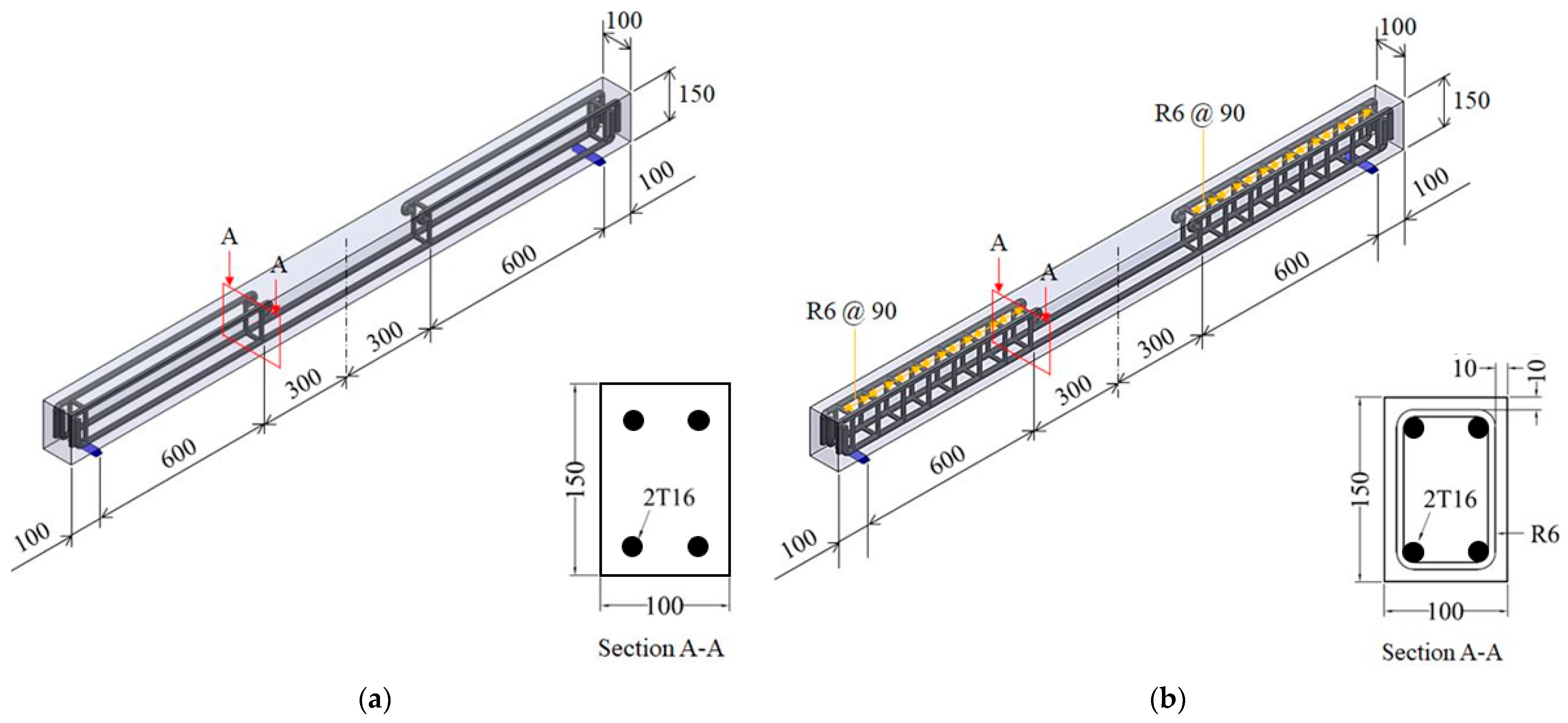
An experimental program was established to explore the effects of selected variables on the shear resistance of reinforced LWAC beams. This study focused on the type of CA and the web reinforcement ratio as the primary variables, informed by findings from previous studies [36,37,38,39]. Measurements taken during the tests included loads at first cracking and ultimate strength, along with crack patterns. Details on the test variables, materials, and experimental procedures are described below.

4.1. Test Variables

Table 1 describes the three types of CAs used to prepare reinforced LWAC beams. Two types of lightweight CAs were used: expanded slate and expanded clay. An expanded slate aggregate commonly utilized in LWAC is produced by heating slate in a rotary kiln at approximately 1200 °C. It has a bulk density ranging from 720 to 880 kg/m3, a particle density of 1394 kg/m3, and a 24 h water absorption ratio of 5.9%. Expanded clay produced from natural clay expanded at high temperatures and features a bulk density of 400 to 800 kg/m3, a particle density of 1449 kg/m3, and a 24 h water absorption rate of 11.9%. A consistent type of expanded clay lightweight fine aggregate was used in casting the reinforced ALWAC specimens. Additionally, a natural CA was included for comparative analysis. Larger aggregate sizes generally enhance strength but also impact ductility and the material’s ability to withstand deformation before failure. Ductility, the ability of a material to deform plastically under stress, is crucial in RC beams, as it influences their capacity to absorb energy prior to failure. Additionally, analyzing the softening branch of the load–deformation curve provides key insights into the post-peak behavior, crucial for understanding how beams may perform under sustained loads or during seismic events [40,41]. Thus, a comprehensive understanding of these factors is essential for designing resilient and safe concrete structures. It should be noted that aggregate size was not a variable in this study; all aggregates used had similar dimensions, as shown in Table 1.
Figure 1 illustrates the schematic diagrams of the cross-sectional and longitudinal reinforcement configurations for the beams studied. Each beam had a uniform effective depth (d) of 126 mm and an a/d of 4.76 [42]. Concrete cover depths were specified at 16.0 mm for beams without stirrups and 10.0 mm for those with stirrups. All beams were longitudinally reinforced with two 16 mm diameter deformed steel bars, standardizing the reinforcement across the series. Additionally, a longitudinal reinforcement ratio of 3.2% was employed to ensure predominantly shear-based failure, supported by transition reinforcement. Four beams were prepared for each type of aggregate: two omitted shear reinforcements, while the other two included steel stirrups spaced at 90 mm intervals. The design also featured bent longitudinal bars at each beam’s ends to provide necessary anchorage. To evaluate the compressive strength, three cylinders, each 100 mm in diameter and 200 mm in height, were prepared for each beam configuration. As shown in Figure 1, the stirrups in the prepared concrete beams were not placed at mid-span, assuming that mid-span stirrups might not significantly affect the test results of this study [43,44,45]. The nomenclature for the beams consists of three letters, each signifying specific characteristics. The first letter indicates the type of concrete used: ‘L’ for LWAC and ‘N’ for NWC. The second letter specifies the presence of steel stirrups, with ‘N’ denoting absence and ‘S’ indicating presence. The third letter identifies the type of CA used. For instance, ‘LNS’ refers to an LWAC beam without stirrups using expanded slate, while ‘NSN’ designates a shear-reinforced NWC beam containing NWA, as detailed in Table 2.

4.2. Materials and Specimen Preparation

Table 3 shows the concrete mix proportions considered in this study. As summarized in Table 4, Type I ordinary Portland cement (OPC; Sampyo Cement, Seoul, Republic of Korea) and silica fume (SF; Elkem 940U; Elkem, Oslo, Norway) were used to prepare the samples. SF, containing approximately 97% SiO2 and with a density of 2.27 g/cm3, was incorporated at a constant replacement ratio of 10% to focus on the impact of different types of lightweight CAs. A polycarboxylate-based high-range water-reducing superplasticizer (SP; Flowmix 3000 U; Dongnam, Gyeonggi-do, Republic of Korea) was also utilized. Figure 2 presents the SEM images, and Figure 3 displays the particle size distributions and XRD results of the raw materials.
Concrete mix proportions for specimen preparation were established by considering the water absorption of LWAs and ensuring the repeatability of targeted properties. The desired strength and density were set at 30 MPa and 1600 kg/m3, respectively. Both coarse and fine lightweight aggregates were pre-soaked for over 24 h to prevent additional water absorption during mixing and casting, thereby maintaining the expected properties. Excess water was removed from the aggregate surfaces using a dry towel to achieve surface-saturated dry (SSD) conditions. Concrete casting and fresh density measurements were conducted repeatedly to refine the mixtures until they achieved the designed density and ensured proper workability. The total mixing time was set at 5 min based on findings from a previous study [46]. The following details outline the concrete mixing procedure adopted in this study:
  • Pre-soaking lightweight coarse and fine aggregates for over 24 h to ensure adequate water absorption and stability.
  • Removing surface water from the aggregates using absorbent cotton towels to achieve SSD conditions.
  • Loading all prepared and measured materials into a drum-type mixer in the following sequence: CAs first, then cement and silica fume, and, finally, sand.
  • Initiating the mixing process by blending for 60 s with half of the total water to ensure an even distribution of moisture.
  • Adding the remaining water along with a high-range water reducer (HRWR) and continuing the mixing for an additional four minutes to achieve the desired consistency and workability of the concrete mix.

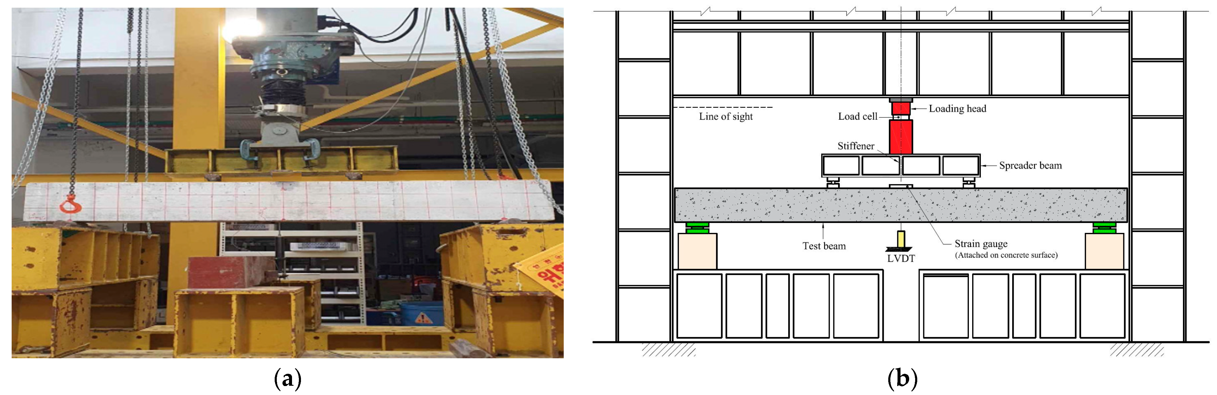
4.3. Testing and Measurements

The compressive strength and density of the concrete samples were measured according to ASTM standards C39 and C138, respectively [47,48]. Measurements were performed using a hydraulic universal testing machine (UTM) with constant loading rates of 900 N/s and 0.02 mm/min. Beam tests were carried out under 4-point static loading conditions, with central deflection, δ, measured at the mid-span using fixed Linear Variable Differential Transformers (LVDTs), as depicted in Figure 4. The load was applied incrementally using a hydraulic jack and maintained briefly to observe the initiation and propagation of flexural cracks. Data on tensile reinforcement strain, concrete strain, applied load, and mid-span deflection were automatically recorded by a connected computer system during the tests, and cracking loads were noted directly on the RC beams. LVDTs with a 100 mm stroke were used to measure the vertical displacement at the determined positions. To observe strain on the reinforcement and concrete, strain gauges manufactured by Tokyo Sokki Kenkyujo Co. Ltd. (TML), Tokyo, Japan were used. Specific strain gauges, such as PL-90-11 (gauge length 90 mm, gauge factor 2.10 ± 1%, resistance 119.90 ± 0.5 Ω) for concrete and FLA-3-11 (gauge length 2 mm, gauge factor 2.10 ± 1%, resistance 120.4 ± 0.5 Ω) for steel, were used to measure the strain. Testing continued until beam failure or the onset of concrete crushing. Following all strength and beam tests, a comparative analysis between measured and estimated values—based on previously summarized equations—was performed. This study investigated the effect of the LWA type used in the beams and the measured concrete strength and density on the shear behavior of the RC beams. Thus, statistical methods were used to analyze the test results, obtaining p-values. A one-way ANOVA test assessed the effect of different LWA types on the shear strength of the beams, testing the null hypothesis that there is no significant difference in strength among the samples.

5. Test Results and Analysis

5.1. Cracking and Failure Behavior

Table 5 presents the 28-day compressive strength, splitting tensile strength, demolding density, and elastic modulus for each tested beam, while Figure 5 and Figure 6 depict the load–deflection curves and crack patterns, respectively. Beams equipped with stirrups typically failed due to flexural shear failure, whereas those without stirrups exhibited diagonal tension failure. In beams with stirrups, an initial inclined crack triggered stress redistribution, activating the stirrups to enhance shear resistance and ultimately leading to flexural failure.
Beams without stirrups initially developed vertical flexural cracks towards the compression side, resulting in significant mid-span deflection and diagonal tensile failure. Additionally, these beams demonstrated higher diagonal crack loads with increased concrete strengths, as shown in Table 5. Specifically, NNN exhibited 11% and 25% higher diagonal crack loads than LNS and LNC, respectively.
However, no significant differences were observed in the ultimate loads and deflections. This similarity might be attributed to the dominant effect of longitudinal reinforcement on post-cracking, as indicated by Carmo et al. [29]. Shear resistance in short beams is achieved through arch action, while in slender beams, it is typically via beam action. Consequently, in this study, slender beams likely relied on beam action to resist shear. Therefore, the primary mechanisms that might govern shear resistance in beams without stirrups are likely to aggregate the interlock and dowel action of the longitudinal reinforcement. Overall, the cracking and failure behavior of the reinforced ALWAC beams was consistent with previous studies reported by Juan [28] and Sathiyamoorthy et al. [32]. As depicted in Figure 6, all beams with stirrups exhibited concrete crushing at the top and underwent flexural shear failure. Table 6 exhibits a comparison between the experimental and theoretical ultimate moments. Mn was estimated through ACI provisions [23]. Based on the analysis, it can be seen that the failure mode of the RC beams with stirrups was primarily due to bending moments, but there was also evidence of concrete crushing at the mid-span, as shown in Figure 6. Consequently, beams exhibited flexural shear failure. This failure mode begins with the formation of cracks due to flexural tensile stress and concludes with the failure of concrete in shear.
ALWAC beams generally exhibited earlier flexural cracks and more brittle failures compared to NWC beams. Specifically, ALWAC beams with stirrups showed more extensive and wider flexural cracks compared to NWC beams under the same loading conditions. This difference may be attributed to the lower tensile strength of ALWAC, as indicated by several studies [11,49,50,51]. Generally, the tensile strength of the aggregate, the surrounding cement mortar, and the interface between the aggregate and the paste can influence concrete cracking. However, in this study, the type of coarse aggregate selected did not significantly affect the flexural behavior of the RC beams, likely due to the high a/d ratio of the stirrups used [31].

5.2. Applied Load and Mid-Span Deflections

NWC demonstrated the highest ultimate load values, with differences of less than 4.0% compared to those of ALWAC specimens. Among the ALWAC beams, those containing expanded clay exhibited the highest mid-span deflection. Figure 7 shows the comparisons of mid-span deflection. Specifically, the mid-span deflection of LNC was 24% greater than that of NNN, while LSC’s deflection exceeded NSN’s by 7%. Additionally, LNS had a 20% higher deflection than NNN, and LSS’s deflection was 5% greater than NSN’s. Overall, ALWAC beams showed structural performance similar to NWC beams under identical loading conditions. Lower shear resistance was initially anticipated in ALWAC due to its brittle cracking behavior, which stemmed from its lower tensile strength. This tendency, likely influenced by the high tensile reinforcement ratio used in this study, aligns with trends observed in previous research. Carmo et al. [29] confirmed the significant effects of a high tensile reinforcement ratio and stirrups on both the deformation capacity and cracking behavior of LWAC beams. Further research may be necessary to clarify the effects of a lower tensile reinforcement ratio on the structural behavior of ALWAC beams.

5.3. Cracking and Ultimate Loads

Figure 8 illustrates the comparisons of the first crack and ultimate loads between ALWAC and NWC beams. NWC beams exhibited higher first and diagonal crack loads compared to ALWAC beams, with the first crack loads of NWC being 0.4 to 49% higher. Additionally, the diagonal crack loads of NSN were 11% and 25% higher than those of LSS and LSC, respectively. Concrete cracks initiate when the tensile strength of the concrete exceeds the principal stresses, and flexural cracks occur in regions of the maximum moment at the beam’s bottom, transverse to the longitudinal axis. Near the supports, large shear forces due to diagonal tension generate inclined diagonal cracks at about 45° to the axis. Thus, the trends in the first and diagonal cracks in ALWAC beams align well with the measured compressive and splitting strength values, while the ultimate loads showed less variance, differing by less than 4%. Therefore, it can be concluded that the cracking loads of ALWAC can be estimated through measured concrete strength, and the post-cracking behavior of the beams is predominantly influenced by tensile reinforcement.

5.4. Measured Strain Values

Concrete and steel strains were measured at every load increment. At service loads, the concrete compressive strains ranged between 400 and 1300 × 10−6. The measured strain values on the concrete surface were quite similar regardless of aggregate type, with no significant differences observed. The measured concrete and steel strain values ranged from 2000 to 5000 × 10−6 and 2000 to 6000 × 10−6, respectively. Strain gauge values attached to the reinforcement were also consistent, regardless of aggregate type. This consistency is logical because all specimens had a uniform arrangement. The homogeneity in strain gauge readings, both on the concrete surface and the reinforcement, indicates that the structural behavior under load was uniformly distributed. This demonstrates that the type of coarse aggregate used did not significantly affect the strain distribution within the RC beams. The uniformity in strain values suggests that the reinforcement detailing and concrete properties were the dominant factors in the structural performance of the beams.

5.5. Shear Resistance and Comparisons

Table 7 presents both the experimental and estimated shear resistances, along with the percentage differences for comparison. The shear resistance, Vc, was estimated to be half of the maximum applied load, attributed solely to the concrete without considering dowel action. Figure 9 displays all measured and estimated shear resistance values of tested beams for better comparison. Both ACI 318 [24] and JSCE [35] underestimated the shear resistance of all beams, while other standards overestimated it for NWC beams, potentially due to factors such as tensile strength and density [30]. The results from JSCE [35] were more conservative compared to other design codes. As a result, the equations summarized in the design codes conservatively calculate the shear resistance for ALWAC beams, enabling their safe application to ALWAC specimens for design purposes. However, further experimental testing on larger beams is necessary to confirm the applicability of these equations. The ANOVA test yielded an F-statistic of 3.334 and a p-value of approximately 0.0557, indicating a higher variance between group means than the overall mean. Although the p-value slightly exceeds the typical significance level of 0.05, it suggests possible differences among the estimated values from different design codes. Nevertheless, the evidence is not strong enough to conclusively reject the null hypothesis at the 5% significance level, indicating that while there is some variation among the estimates from different codes, this variation is not statistically significant.
Overall, all the considered design codes underestimated the shear capacity of the tested ALWAC beams with a constant a/d ratio of 4.76 used in this study. It can be concluded that the shear resistance estimated through EC2 matched better than other methods, although the differences were not statistically significant.

5.6. Effect of Coarse Aggregate Type on Shear Resistance of RC Beams

In this study, ALWAC mix proportions were developed and applied in the preparation of RC beams. The mix proportions exhibited good repeatability in ensuring the designed concrete properties, even though only a limited number of LWAs were considered. Furthermore, through beam testing, we observed that ALWAC beams displayed earlier and wider crack regions compared to NWC beams. Thus, it was initially expected that the use of LWAs might negatively influence the shear behavior of RC beams because of the lower cracking load. However, the effect of the coarse aggregate was not significant. Studies have shown that although LWAs tend to decrease the initial cracking load, their overall impact on the ultimate shear resistance of RC beams is minimal. This is because the primary factors influencing shear strength are concrete strength and reinforcement detailing rather than the type of coarse aggregate. Consequently, while LWAs might slightly alter the initial cracking behavior, they do not substantially affect the ultimate shear capacity, making them a viable option for structural applications where weight reduction is a priority.

6. Limitations and Future Studies

In this study, we explored the shear capacity of ALWAC beams under monotonic loading and confirmed that the type of aggregate does not significantly affect shear resistance as it is. However, ALWAC beams exhibited inferior capacity, showing more extensive crack propagation under identical loading conditions compared to NWC beams. Notably, there were discrepancies between the measured shear strength values and those predicted by existing codes and guidelines, underscoring the urgent need for further research into the structural performance of ALWAC structures.
Future research should examine how the properties of lightweight aggregates, such as density and water absorption, influence the mechanical behavior of ALWAC. The integration of polymers and other emerging materials might enhance the flexibility and crack resistance of ALWAC beams. Long-term studies are essential to assess the impact of environmental factors like moisture, temperature fluctuations, and chemical exposure on the aging of these beams. Moreover, developing advanced predictive models that incorporate a range of material and loading factors and potentially integrating artificial intelligence and machine learning could significantly improve prediction accuracy. Testing methods should also be expanded to include various stress types, such as cyclic, seismic, and impact loads, to better understand ALWAC’s behavior under real-world conditions. Comprehensive evaluations of the environmental impacts of different lightweight aggregates and the benefits of using polymers in ALWAC are crucial, aiming to balance structural efficiency with environmental sustainability. Promoting the use of recycled and local materials will further advance ALWAC technology, leading to the creation of more sustainable and resilient structures.
Lastly, this study focused on the effect of LWA type and the presence of stirrups on the shear behavior of LWAC beams. However, several other crucial design parameters—including beam height, cross-section geometry, aggregate dimensions, and strength-reduction factors—significantly influence the structural performance of reinforced LWAC beams and merit further investigation. These parameters are pivotal in determining the beams’ load-carrying capacity and enhancing ductility. Specifically, beam height and cross-section geometry affect the bending and shear capacities, while aggregate strength may influence the ability to resist shear forces. Additionally, factors like reinforcement detailing, which include the spacing and diameter of reinforcement bars, play a crucial role in controlling crack widths and improving ductility.

7. Conclusions

In this study, the effect of different types of lightweight coarse aggregates on the structural performance of ALWAC beams was experimentally investigated, yielding the following conclusions:
  • ALWAC beams with stirrups exhibited more extensive and wider flexural cracks compared to NWC beams under the same loading conditions. This difference may be attributed to the lower tensile strength of ALWAC.
  • The type of lightweight coarse aggregate selected did not significantly affect the flexural behavior of the RC beams, possibly due to the high a/d ratio adopted in this study.
  • ALWAC beams demonstrated structural performance similar to that of NWC beams under identical loading conditions.
  • The cracking loads of ALWAC can be estimated through measured concrete strength, with the post-cracking behavior of the beams predominantly influenced by tensile reinforcement.
  • All considered design codes underestimated the shear capacity of the tested ALWAC beams, and the shear resistance estimated by EC2 was better matched than that of other methods, although the differences were not statistically significant.
  • The developed mix proportions demonstrated consistent results in achieving the desired concrete properties, despite the limited variety of LWAs used. Additionally, beam tests revealed that ALWAC beams exhibited earlier and more extensive cracking compared to NWC beams.
Lastly, the limitations and future work based on the results of this study were discussed and summarized.

Author Contributions

Conceptualization, S.C. and M.O.K.; methodology, M.O.K.; software, S.C.; validation, S.C. and M.O.K.; formal analysis, S.C.; investigation, S.C.; resources, M.O.K.; data curation, S.C.; writing—original draft preparation, S.C.; writing—review and editing, M.O.K.; visualization, S.C. and M.O.K.; supervision, M.O.K.; project administration, M.O.K.; funding acquisition, M.O.K. All authors have read and agreed to the published version of the manuscript.

Funding

This study was supported by the research program funded by SeoulTech (Seoul National University of Science and Technology) (grant no. 2021-0970).

Data Availability Statement

The original contributions presented in the study are included in the article, further inquiries can be directed to the corresponding authors.

Acknowledgments

The authors express sincere gratitude to the Seoul National University of Science and Technology for financial support.

Conflicts of Interest

The authors declare no conflicts of interest.

Appendix A

Table A1. Strength and density requirements of LWAC and modification (reduction) factors for shear, according to existing codes [23,24,25,26,32,33,34,35].
RequirementACI 213 [32],
ACI 318 [23,24]
BS 8110 [26]CSA [34]EC2 [25]JSCE [35]
f’c 1f’c ≥ 17.0 MPaConcrete strength classes ≥ LC20/22f’c ≥ 20.0 MPaNot specifiedNot specified
(less than 60.0 MPa)
ρc 21120–1920 kg/m3ρc ≤ 2000 kg/m3ρc ≤ 1850 kg/m3
(low density)
1850–2150 kg/m3
(semi-low density)
ρc ≤ 2000 kg/m31200–1700 kg/m3
(Type I 4)
1600–2100 kg/m3
(Type II 5)
λ 30.75 (ALWAC)
0.85 (LWAC)
1.00 (NWC)
0.800.75
(low density)
0.85
(semi-low density)
0.40 + 0.60ρc/22000.70
1 f’c: concrete compressive strength; 2 ρc: concrete density; 3 λ: modification factor or strength reduction factor; 4 both the CA and FA are either a lightweight aggregate or a partially normal aggregate; 5 the CA is either a lightweight aggregate or a partially normal aggregate and the FA is a normal aggregate.

References

  1. Melby, K.; Jordet, E.A.; Hansvold, C. Long-span bridges in Norway constructed in high-strength LWA concrete. Eng. Struct. 1996, 18, 845–849. [Google Scholar] [CrossRef]
  2. Haug, A.K.; Fjeld, S. A floating concrete platform hull made of lightweight aggregate concrete. Eng. Struct. 1996, 18, 831–836. [Google Scholar] [CrossRef]
  3. Gerwick, B.C., Jr. Introduction. In Construction of Prestressed Concrete Structures, 2nd ed.; John Wiley & Sons, Inc.: New York, NY, USA, 1997; pp. 11–52. [Google Scholar]
  4. Rossignolo, J.A.; Agnesini, M.V.C.; Morais, J.A. Properties of high-performance LWAC for precast structures with Brazilianlightweight aggregates. Cem. Concr. Compos. 2003, 25, 77–82. [Google Scholar] [CrossRef]
  5. Holm, T.A.; Bremner, T.W. Durability of Structural Lightweight Concrete. Spec. Publ. 1991, 126, 1119–1134. [Google Scholar]
  6. Mo, K.H.; Ling, T.-C.; Alengaram, U.J.; Yap, S.P.; Yuen, C.W. Overview of supplementary cementitious materials usage in lightweight aggregate concrete. Constr. Build. Mater. 2017, 139, 403–418. [Google Scholar] [CrossRef]
  7. Cavalline, T.L.; Castrodale, R.W.; Freeman, C.; Wall, J. Impact of Lightweight Aggregate on Concrete Thermal Properties. ACIMater. J. 2017, 114, 945–956. [Google Scholar] [CrossRef]
  8. Lesovik, R.V.; Botsman, L.N.; Tarasenko, V.N.; Botsman, A.N. Enhancement of sound insulation of floors using light-weight concrete based on nanostructured granular aggregate. ARPN J. Eng. Appl. Sci. 2014, 9, 1789–1793. [Google Scholar]
  9. Guneyisi, E.; Gesoğlu, M.; Ghanim, H.; Ipek, S.; Taha, I. Influence of the artificial lightweight aggregate on fresh properties and compressive strength of the self-compacting mortars. Constr. Build. Mater. 2016, 116, 151–158. [Google Scholar] [CrossRef]
  10. He, K.-C.; Guo, R.-X.; Ma, Q.-M.; Yan, F.; Lin, Z.-W.; Sun, Y.-L. Experimental Research on High Temperature Resistance of Modified Lightweight Concrete after Exposure to Elevated Temperatures. Adv. Mater. Sci. Eng. 2016, 2016, 5972570. [Google Scholar] [CrossRef]
  11. Haque, M.N.; Al-Khaiat, H.; Kayali, O. Strength and Durability of Lightweight Concrete. Cem. Concr. Compos. 2004, 26, 307–314. [Google Scholar] [CrossRef]
  12. Kockal, N.U.; Ozturan, T. Durability of Lightweight Concretes with Lightweight Fly Ash Aggregates. Constr. Build. Mater. 2011, 25, 1430–1438. [Google Scholar] [CrossRef]
  13. Aslam, M.; Shafigh, P.; Jumaat, M.Z. Oil-Palm by-Products as Lightweight Aggregate in Concrete Mixture: A Review. J. Clean. Prod. 2016, 126, 56–73. [Google Scholar] [CrossRef]
  14. Kılıç, A.; Atiş, C.D.; Yaşar, E.; Özcan, F. High-Strength Lightweight Concrete Made with Scoria Aggregate Containing Mineral Admixtures. Cem. Concr. Res. 2003, 33, 1595–1599. [Google Scholar] [CrossRef]
  15. Thomas, M.; Bremner, T. Performance of Lightweight Aggregate Concrete Containing Slag after 25 years in a Harsh Marine Environment. Cem. Concr. Res. 2012, 42, 358–364. [Google Scholar] [CrossRef]
  16. Chai, L.J.; Shafigh, P.; Bin Mahmud, H. Production of High-Strength Lightweight Concrete Using Waste Lightweight Oil-Palm-Boiler-Clinker and Limestone Powder. Eur. J. Environ. Civ. Eng. 2019, 23, 325–344. [Google Scholar] [CrossRef]
  17. Mansouri, E.; Manfredi, M.; Hu, J.-W. Environmentally Friendly Concrete Compressive Strength Prediction Using Hybrid Machine Learning. Sustainability 2022, 14, 12990. [Google Scholar] [CrossRef]
  18. Hossain, K.M.A.; Ahmed, S.; Lachemi, M. Lightweight Concrete Incorporating Pumice Based Blended Cement and Aggregate: Mechanical and Durability Characteristics. Constr. Build. Mater. 2011, 25, 1186–1195. [Google Scholar] [CrossRef]
  19. Chen, S.-H.; Wang, H.-Y.; Jhou, J.-W. Investigating the Properties of Lightweight Concrete Containing High Contents of Recycled Green Building Materials. Constr. Build. Mater. 2013, 48, 98–103. [Google Scholar] [CrossRef]
  20. Thienel, K.-C.; Haller, T.; Beuntner, N. Lightweight concrete—From basics to innovations. Materials 2020, 13, 1120. [Google Scholar] [CrossRef]
  21. Gerritse, A. Design considerations for reinforced lightweight concrete. Int. J. Cem. Compos. Light. Concr. 1981, 3, 57–69. [Google Scholar] [CrossRef]
  22. Ting, T.Z.H.; Rahman, M.E.; Lau, H.H.; Ting, M.Z.Y. Recent development and perspective of lightweight aggregates based self-compacting concrete. Constr. Build. Mater. 2019, 201, 763–777. [Google Scholar] [CrossRef]
  23. ACI 318-14; Building Code Requirements for Structural Concrete. American Concrete Institute: Farmington Hills, MI, USA, 2014.
  24. ACI 318-11; Building Code Requirements for Structural Concrete. American Concrete Institute: Farmington Hills, MI, USA, 2011.
  25. Eurocode 2: European Committee for Standardization. Design of Concrete Structures—Part 1–2: General Rules; Structural Fire Design: Brussels, Belgium, 2004. [Google Scholar]
  26. BS8110-1:1997; British Standards Institution Structural Use of Concrete. BSI: London, UK, 1997.
  27. Ahmad, S.H.; Xie, Y.; Yu, T. Shear Ductility of Reinforced Lightweight Concrete Beams of Normal Strength and High Strength Concrete. Cem. Concr. Compos. 1995, 17, 147–159. [Google Scholar] [CrossRef]
  28. Juan, K.Y. Cracking Mode and Shear Strength of Lightweight Concrete Beams. Ph.D. Thesis, National University of Singapore, Singapore, 2011. [Google Scholar]
  29. Carmo, R.N.F.; Costa, H.; Lourenço, C.; Andrade, D.; Simões, T. Influence of both concrete strength and transverse confinement on bending behaviour of reinforced LWAC beams. Eng. Struct. 2013, 48, 329–341. [Google Scholar] [CrossRef]
  30. Yang, K.-H.; Ashour, A.F. Modification factor for shear capacity of lightweight concrete beams. ACI Struct. J. 2015, 4, 485–492. [Google Scholar] [CrossRef]
  31. Bernardo, L.F.; Nepomuceno, M.C.; Pinto, H.A. Flexural ductility of lightweight-aggregate concrete beams. J. Civ. Eng. Manag. 2016, 22, 622–633. [Google Scholar] [CrossRef]
  32. Sathiyamoorthy, K.; Hossain, K.M.A.; Lofty, A. Shear Resistance of Lightweight Self-Consolidating Concrete Beams. In Proceedings of CSCE 2016 Resilient Infrastructure, London, ON, Canada, 1–4 June 2016. [Google Scholar]
  33. ACI 213R-14; Guide for Structural Lightweight-Aggregate Concrete. American Concrete Institute: Farmington Hills, MI, USA, 2014.
  34. CSA CAN3-A23.3; Design of Concrete Structures. Canadian Standards Association: Rexdale, ON, Canada, 2004.
  35. Japan Society of Civil Engineers. Standard Specifications for concrete structures-2007 Materials and Construction. JSCE Guidel. Concr. 2010, 16. [Google Scholar]
  36. Alqarni, A.S.; Albidah, A.S.; Alaskar, A.M.; Abadel, A.A. The effect of coarse aggregate characteristics on the shear behavior of reinforced concrete slender beams. Constr. Build. Mater. 2020, 264, 120189. [Google Scholar] [CrossRef]
  37. Herki, B.M.; Khatib, J. Structural behaviour of reinforced concrete beams containing a novel lightweight aggregate. Int. J. Struct. Eng. 2015, 7, 1. [Google Scholar] [CrossRef]
  38. Li, X.K.; Li, C.Y.; Zhao, M.L.; Yang, H.; Zhou, S.Y. Testing and Prediction of Shear Performance for Steel Fiber Reinforced Expanded-Shale Lightweight Concrete Beams without Web Reinforcements. Materials 2019, 12, 1594. [Google Scholar] [CrossRef]
  39. Kang, T.H.-K.; Kim, W.; Kwak, Y.-K.; Hong, S.-G. Shear Testing of Steel Fiber-Reinforced Lightweight Concrete Beams without Web Reinforcement. ACI Struct. J. 2011, 108, 553. [Google Scholar]
  40. Gusella, F.; Orlando, M. Failure analysis and retrofitting of reinforced concrete beams in existing moment resisting frames. Eng. Fail. Anal. 2023, 153, 107601. [Google Scholar] [CrossRef]
  41. Foraboschi, P. Bending load-carrying capacity of reinforced concrete beams subjected to premature failure. Materials 2019, 12, 3085. [Google Scholar] [CrossRef] [PubMed]
  42. Tauqir, M.; Qazi, A.U.; Khan, Q.S.; Munir, M.J.; Kazmi, S.M.S. Shear Behavior of Geopolymer Concrete Slender Beams. Buildings 2023, 13, 1191. [Google Scholar] [CrossRef]
  43. Yang, K.-H.; Sim, J.; Choi, B.; Lee, E. Effect of Aggregate Size on Shear Behavior of Lightweight Concrete Continuous Slender Beams. ACI Mater. J. 2011, 108, 501. [Google Scholar]
  44. Teo, D.C.L.; Mannan, M.A.; Kurian, J.V. Flexural behaviour of reinforced lightweight concrete beams made with oil palm shell (OPS). J. Adv. Concr. Technol. 2006, 4, 459–468. [Google Scholar] [CrossRef]
  45. Tang, C.W.; Yen, T.; Chen, H.J. Shear behavior of reinforced concrete beams made with sedimentary lightweight aggregate without shear reinforcement. J. Mater. Civ. Eng. 2009, 21, 730–739. [Google Scholar] [CrossRef]
  46. Kan, A.; Demirboğa, R. A novel material for lightweight concrete production. Cem. Concr. Compos. 2009, 31, 489–495. [Google Scholar] [CrossRef]
  47. ASTM C39/C39M; Standard Test Method for Compressive Strength of Cylindrical Concrete Specimens. ASTM International: West Conshohocken, PA, USA, 2014.
  48. ASTM C138/C138M-23; Standard Test Method for Density (Unit Weight), Yield, and Air Content (Gravimetric) of Concrete. Annual Book of ASTM Standards. ASTM International: West Conshohocken, PA, USA, 2023.
  49. Zhang, M.H.; Gjorv, O.E. Mechanical properties of high-strength lightweight concrete. ACI Mater. J. 1991, 88, 240–247. [Google Scholar]
  50. Hoff, G. High strength lightweight aggregate concrete for artic applications—Part 1–3. In Structural Lightweight Aggregate Concrete Performance; ACI SP-136; Holm, T.A., Vaysburd, A.M., Eds.; ACI: Farmington Hills, MI, USA, 1992. [Google Scholar]
  51. Roberts-Wollmann, C.L.; Banta, T.; Bonetti, R.; Charney, F. Bearing strength of lightweight concrete. ACI Mater. J. 2006, 103, 459. [Google Scholar]
Figure 1. Beam specimen details: (a) beam without stirrups and (b) beam with stirrups (all dimensions are in mm).
Applsci 14 05992 g001
Figure 2. SEM images of raw materials: (a) OPC and (b) SF.
Applsci 14 05992 g002
Figure 3. (a) Particle size distributions and (b) XRD patterns of raw materials.
Applsci 14 05992 g003
Figure 4. (a) Beam testing photo and (b) test setup.
Applsci 14 05992 g004
Figure 5. Load–deflection curves of beams (a) without stirrups and (b) with stirrups.
Applsci 14 05992 g005
Figure 6. Cracking and failure patterns of representative beams: (a) LNS, (b) LSS, (c) LNC, (d) LSC, (e) NNN, and (f) NSN.
Applsci 14 05992 g006
Figure 7. Comparison of mid-span deflection of beams (a) without stirrups and (b) with stirrups.
Applsci 14 05992 g007
Figure 8. Comparisons of first cracking and ultimate loads of beams (a) without stirrups and (b) with stirrups.
Applsci 14 05992 g008
Figure 9. Results of (a) experimental and estimated shear resistance; (b) percentage differences (estimated/experimental).
Applsci 14 05992 g009
Table 1. Coarse aggregate details.
Type of Lightweight
Coarse Aggregate
Bulk Density
(kg/m3)
Particle Density
(kg/m3)
24 h Water Absorption (%)Maximum Size
(mm)
Shape
Expanded slate84913945.912Angular
Expanded clay469144911.910Spherical
Normal1563-1.1313Angular
Table 2. Beam specimen details.
IDLength
(mm)
Width
(mm)
Depth
(mm)
Effective Depth, d (mm)a/dLongitudinal
Reinforcement
(mm)
Stirrups
Spacing
(mm)
Type of
Coarse
Aggregate
LNS20001001501264.7616-Expanded slate
LSS90
LNC-Expanded clay
LSC90
NNN-Normal
NSN90
Table 3. Concrete mix proportions considered in this study (unit: kg).
IDOPCSFCA FA Water SPCA Type
LNS and LSS450504496561805Expanded slate
LNC and LSCExpanded clay
NNN and NSNNormal
Table 4. Chemical characteristics (in mass %) of raw materials.
Constituent (%)OPCSF
CaO61.401.54
SiO221.2396.90
Al2O35.640.29
Fe2O33.380.15
MgO2.200.18
SO32.25
K2O1.150.64
Na2O0.110.16
Cl0.06
MnO0.03
P2O5-0.05
Loss of Ignition2.580.05
Table 5. Measured concrete properties and beam test results.
IDf’cf’spρEFirst CrackInclined Diagonal CrackUltimate
LoadDeflectionLoadDeflectionLoadDeflection
(MPa)(MPa)(kg/m3)(GPa)(kN)(mm)(kN)(mm)(kN)(mm)
LNS35.042.87153117.7114.982.8130.116.1332.978.02
LSS10.051.74--56.8913.01
LNC33.792.79158017.6914.042.7226.835.8132.219.64
LSC11.982.09--56.5613.61
NNN41.283.13177222.5915.043.1233.427.7633.377.76
NSN14.992.58--58.5412.76
Table 6. Comparison between the experimental and theoretical ultimate moments [23].
IDMaximum Bending Moment, Mu
(kNm)
Resistance Bending Moment, Mn
(kNm)
Capacity Ratio of Concrete Beams,
Mu/Mn
LSS17.0716.311.05
LSC16.9716.131.05
NSN17.5617.011.03
Table 7. Measured and estimated shear resistances of beams.
IDExperimental,
Vc
Estimated Values and Percentage Differences (Estimated/Experimental)
ACI 318
[23,24,32]
BS 8110
[26]
CSA
[34]
EC2
[25]
JSCE
[35]
kNkN (%)kN (%)kN (%)kN (%)kN (%)
LNS16.4911.77 (71.39)14.54 (88.14)14.54 (88.20)14.90 (90.37)8.52 (51.68)
LNC16.1111.48 (71.28)14.36 (89.13)14.28 (88.66)14.96 (92.88)8.51 (52.81)
NNN16.6912.71 (76.14)19.43 (116.43)21.05 (126.11)20.40 (122.26)13.50 (80.89)
Disclaimer/Publisher’s Note: The statements, opinions and data contained in all publications are solely those of the individual author(s) and contributor(s) and not of MDPI and/or the editor(s). MDPI and/or the editor(s) disclaim responsibility for any injury to people or property resulting from any ideas, methods, instructions or products referred to in the content.

