Article

Research on Mechanism of Non-Uniform In-Situ Stress Induced Casing Damage Based on Finite Element Analysis

1
School of Human Settlements and Civil Engineering, Xi’an Jiaotong University, Xi’an 710049, China
2
Oil and Gas Technology Research Institute of Changqing Oilfield, China National Petroleum Corporation, Xi’an 710018, China
3
Oil Production Plant NO. 5 of Changqing Oilfield, China National Petroleum Corporation, Xi’an 710201, China
*
Author to whom correspondence should be addressed.
Appl. Sci. 2024, 14(14), 5987; https://doi.org/10.3390/app14145987
Submission received: 27 May 2024 / Revised: 4 July 2024 / Accepted: 6 July 2024 / Published: 9 July 2024

Abstract

:
Casing damage is a common problem encountered during oil and gas field development due to the complex stress state of the casing. Despite the large number of studies focusing on this problem, the mechanism of non-uniform in-situ stress-induced casing damage in a low-permeability reservoir is still unclear. In this study, casing damage due to non-uniform in-situ stress variations was investigated, and then the tectonic stress coefficients in the study area were determined by an in-situ stress inversion technique, which led to the derivation of formulas for calculating the maximum and minimum horizontal in-situ stresses. Subsequently, finite element numerical simulations were performed to assess the stress distribution during the formation of the casing cement sheath in a G155 block, a typical low-permeability reservoir. The results indicate that casing damage is caused not only by non-uniform in-situ stresses but also by various additional creep-induced loads. Subsequent finite element investigations into casing behavior under mudstone creep conditions indicated that immersion of mudstone in water instigated further shearing and deformation of the casing, culminating in premature well failure prior to water inundation. Notably, Von Mises stress levels exhibited a positive correlation with injection production ratios, with values exceeding critical thresholds leading to distinct modes of mechanical failure including shear-induced deformations, longitudinal tensile stress, and localized yielding near water wells. Maintenance of an optimal injection production ratio is identified as a key strategy for prolonging casing longevity in the region. To this end, recommendations include augmenting the casing wall thickness or enhancing the steel pressure specifications to mitigate casing damage progression, thereby extending the operational lifespan. This research serves as a pivotal theoretical framework for informing future development strategies aimed at mitigating and preempting casing failures in a low-permeability reservoir.

1. Introduction

Casing damage, an inevitable challenge in petroleum engineering, has been constraining the progress of the oil and gas industry [1,2,3,4]. It not only disrupts regular production and wellbore stability but also leads to abnormal injection–production ratios and formation pressure near the affected well, thereby hampering orderly oilfield production [5,6,7,8]. Casing damage is a longstanding challenge in oilfield development, influenced by geological factors, engineering aspects, corrosive environments, and the synergistic impact of these factors [9,10,11,12]. Such damage leads to an incomplete injection–production network, uncontrolled geological reserves, decreased crude oil recovery rates, the disruption of established development procedures, increased safety and environmental hazards, as well as substantial impediments to maintaining stable and efficient oilfield production [13,14,15].
Casing damage in oil fields is a prevalent occurrence on a global scale [16,17,18]. In the United States, casing damage primarily occurs in northwestern oil fields like California and Montana, including locations such as the Belridge oil field, Wilmington oil field, and Lost Hill oil field, among others. There is also severe casing damage in heavy oil production wells in the Alberta region of Canada [19]. The Groningen Gas Field in the Netherlands, the Bolivar Coastal Oil Field in Venezuela, and the Po Delta Gas Field in Italy have all experienced casing damage, mostly due to significant formation compaction and casing shear damage caused by excessive oil reservoir exploitation. Some oil fields in Asia, such as India and Iran, have also experienced casing damage [16]. In China, casing damage in oil and gas wells was first discovered in the Yumen Oilfield. With the extension of development time, casing damage has been discovered in oilfields such as Daqing, Jilin, and Jianghan [8,20,21]. Since the 1990s, large-scale regional casing damage has occurred in oil fields such as Daqing Sazhong, Jilin Fuyu, Yumen Laojunmiao, and Changqing Jurassic, resulting in huge economic losses and forcing some oil wells in certain blocks to be shut down or even scrapped. In 2022, the oil and gas equivalent of the Changqing Oilfield exceeded 65 million tons, becoming the largest oilfield in China. As of the end of 2022, there were a total of 1774 casing-damaged wells in the Changqing Oilfield, resulting in an annual production capacity loss of approximately 1.15 million tons, which is equivalent to a decrease of 1.7% in the annual oil and gas equivalent of the oilfield. Currently, an estimated 20,000 casing-damaged wells exist in China, with the number of such wells across different oil fields continuing to increase.
The mechanism of casing damage varies according to the geological characteristics of the reservoir. Casing deterioration is a multifaceted process shaped by all phases from drilling to development, encompassing oil extraction. It involves rock mechanics, fluid dynamics, string mechanics, and the amalgamation of multiple disciplines, resulting in a wide array of intricate types and mechanisms of casing damage [22]. Understanding the induction mechanism of casing damage has been a recent focus and research challenge [23,24]. In the 1970s and 1980s, scholars investigated the effect of non-uniform loads on the casing’s outer wall, employing stress superposition to derive theoretical formulas for internal stress changes in the casing. Soviet researchers devised an experimental apparatus to simulate the compression impact of rock viscoelastic flow on the casing’s outer wall, studying the forces exerted on it. This experiment yielded data on casing wall stress variations and rock viscoelastic expansion. Ewy et al. employed the modified Lade criterion to predict wellbore stability [25]. Dusseault et al. qualitatively analyzed the effects of formation shear stress, formation dislocation, and reservoir stress on casing failure [7].
Scholars have employed finite element methods to investigate the mechanism of casing damage in water injection oilfields [26,27,28]. They have focused on studying the causes and patterns of casing damage during the high-pressure water injection stage. It has been observed that, with current cementing quality and development technology, high-pressure water injection penetrates weak mudstone interlayers, creating a submerged water area. This leads to changes in in-situ stress within the submerged water area and formation displacement, which is the primary cause of casing damage [29,30,31]. Scholars have proposed a calculation method for casing stress and strength under elliptical non-uniform external loads caused by rock creep, elucidating the mechanical factors behind casing compression damage [32,33,34,35]. Extensive indoor research, wellbore corrosion coupon test analysis of the Luohe Formation in the Changqing Oilfield, and water quality analysis have highlighted the role of corrosion in exacerbating casing damage severity in different areas of the Changqing Oilfield. In summary, excessive development resulting in formation compaction and settlement is the predominant cause of casing damage in foreign oilfields, whereas water injection development and corrosion are the main inducing factors in domestic oilfields.
This research focuses on the low permeability reservoir G155 in the Changqing Oilfield as a representative area with concentrated casing damage. The study delves into the mechanical mechanisms underlying casing damage. It commences by offering an overview of the G155 block and detailing the present scenario of casing deterioration in this region. Subsequently, casing damage is classified from a mechanical standpoint. The distribution of impaired well segments and the longevity of these wells are then subject to statistical analysis. The research predominantly concentrates on casing deformation, specifically examining the surface stress conditions of the casing and cement sheath under non-uniform in-situ stress. A two-dimensional finite element mechanical model of the casing-cement sheath assembly is formulated to simulate variations in Von Mises stress due to differences in maximum and minimum horizontal principal stresses. It is observed that casing deformation in this area is influenced not only by non-uniform in-situ stress but also by other creep-related additional load factors. Additionally, a three-dimensional finite element model is established to analyze the impact of mudstone creep as an additional load on casing stress and examine the characteristics of casing damage. Comprehending the mechanical mechanisms of casing damage in the G155 block aids in laying a theoretical foundation for mitigating and addressing such issues, thereby prolonging the operational lifespan of oil and water wells and fostering the sustainable advancement of oil fields.

2. Characterization of Casing Damage in the G155 Block

2.1. Block Overview

The G155 block is a key development block within the Changqing Jiyuan Oilfield, situated structurally in the western region of the Shaanbei Slope. It pertains to a delta plain surface sedimentation and serves as a structurally lithologic oil reservoir. The main production layer is Chang1, with an average thickness of 12.9 m and a medium depth of 1900 m. The average porosity is 14.7% and the average permeability is 6.5 × 10⁻³ μm2, belonging to a typical low permeability tight oil reservoir with a water flooding recovery rate of only 20.0%. From 2006 to 2009, a square reverse nine-point well network was adopted for production construction and synchronous water injection development. There are 114 oil production wells and 48 water injection wells in the G155 block. Since its production and development, the water content in the block has been continuously increasing due to factors such as damage to water injection wells and production machine casings, and the interval between water content increases is becoming shorter and faster, resulting in increased production capacity loss due to water flooding.

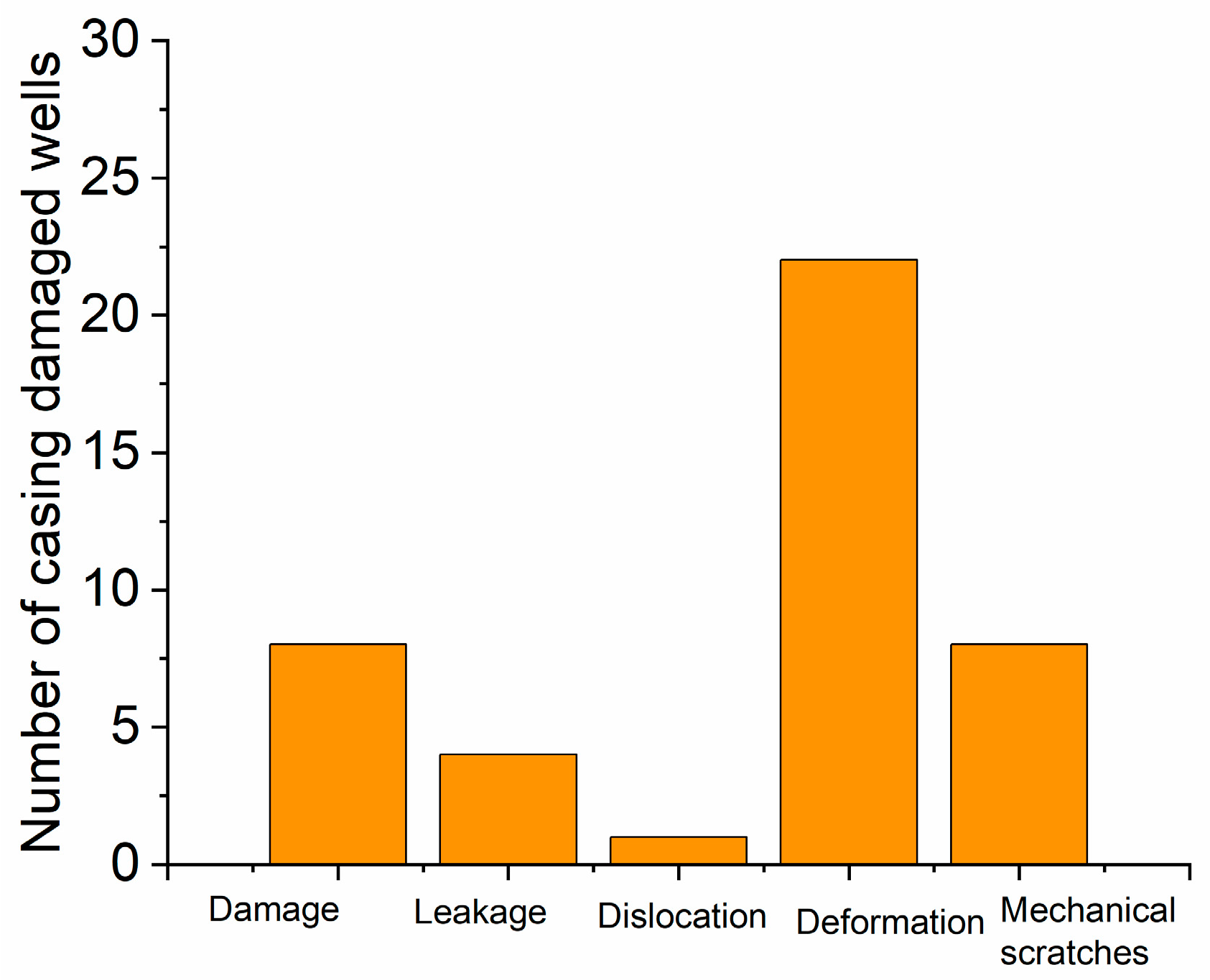
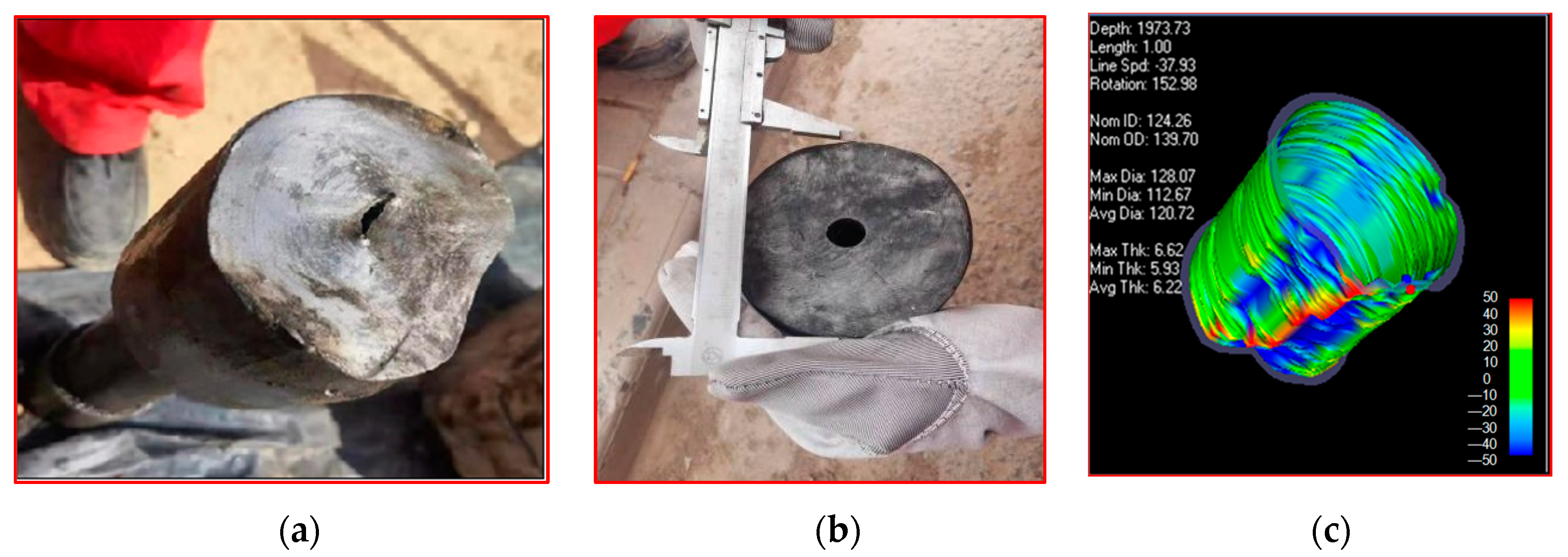
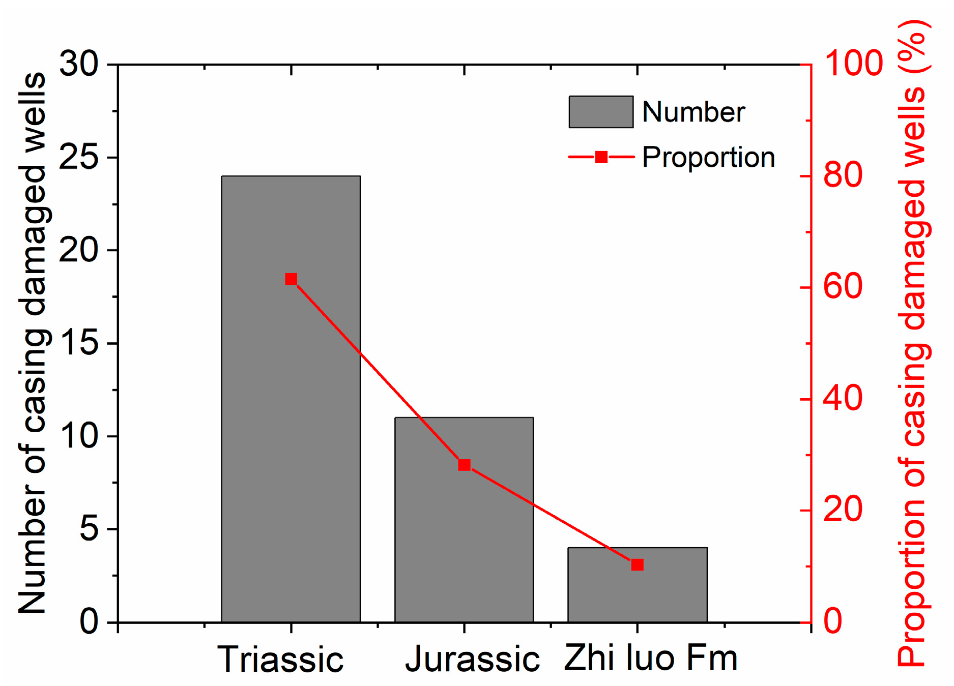
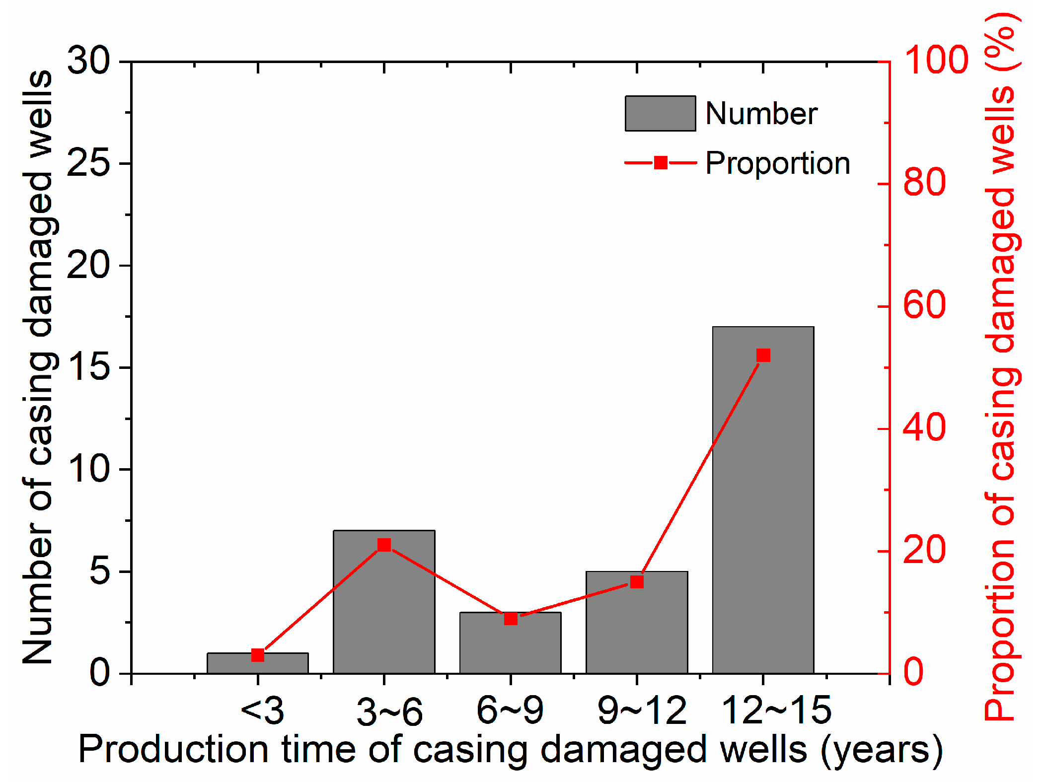
2.2. Situation of Casing Damage

As of the end of 2022, there are a total of 39 casing damage wells in the G155 block. According to the mechanical action types of casing damage, it can be divided into five categories: damage, leakage, dislocation, deformation, and mechanical scratches. The number of wells with different types of casing damage is shown in Figure 1. It can be seen that the number of deformed damaged wells is the highest, reaching 22, accounting for 56.4% of the total number of damaged wells. Casing deformation is the main characteristic type of casing damage in the G155 block.
In the actual production of the G155 block, the damage to the casing can be visually observed through the traces of lead printing, especially the deformation cross-section shape of the casing (Figure 2a,b). Engineering logging can be used to explain the casing damage situation of production wells (Figure 2c).
The proportion of casing-damaged wells in different layers of the G155 block is shown in Figure 3. It can be seen that the distribution range of casing damage wells in this area is wide, and casing damage exists in both oil and non-oil layers. On the plane, casing damage wells first concentrated in the central and eastern parts of the block, and then gradually spread to the entire area. Vertically, casing damage wells are concentrated in the Triassic and Jurassic systems, accounting for 89.7% of the total casing damage wells in the area. Individual perforations occur in casings above the Zhiluo formation, accounting for 10.3% of the total casing damage wells in the area.
The service life of a damaged casing well refers to the production time from the start of production to the time when the casing is damaged. The service life statistics of casing-damaged wells in the G155 block are shown in Figure 4. It can be seen that the production time of most casing-damaged wells in this area exceeds 10 years, accounting for 51.0% of the total casing-damaged wells in the area. Overall, the longer the service life is, the greater is the number of casing-damaged wells, indicating that the load force causing casing damage is formed quickly and concentrated.

3. Theoretical Force Analysis of Casing Damaged Wells

3.1. Basic Theory

While there is general consensus on the mechanism of casing damage among researchers, variations exist in research methodologies. A large number of scholars have explored the law of casing damage caused by mudstone creep under non-uniform in-situ stress conditions. The research on the external squeezing force caused by mudstone creep on the casing is mainly based on two methods: an experimental method and a theoretical calculation method. The research methods for the stress of casing damage are the finite element method and fracture mechanics method. In addition, previous studies have shown that during water injection development, the formation of pore pressure increases, and the injected water enters the mudstone layer, causing changes in the local stress field. The increase in horizontal in-situ stress on the wellbore creates a non-uniform in-situ stress field, which will induce casing deformation or damage. The key to casing damage, whether caused by geological factors or the combination of geological and engineering factors, is that as long as the external force exceeds the bearing capacity of the casing, casing damage will occur. Therefore, from a mechanical perspective, the underlying causes of casing damage are considered, and the basic connection between casing damage and the casing damage mechanism is established as follows:
σ c M a x γ σ o
In the equation, σ c M a x is the maximum stress that the casing can withstand; γ is the allowable safety factor for the casing design, ranging from 1.5 to 4.0; σo is the stress generated by an external load on the casing, which is obtained from a filed measurement.
The stress generated by external loads on the casing is the focus of research, including the changes in external loads caused by mudstone creep, the collapse strength of the casing, and the tensile shrinkage of the casing. It boils down to studying the stress state of casing under non-uniform in-situ stress conditions and predicting and diagnosing the possibility of casing damage based on the magnitude of in-situ stress in a certain formation or well section. There are three mutually perpendicular principal stresses in the strata, namely the vertical in-situ stress caused by the self-weight of rock and the two-horizontal principal in-situ stresses. In general, the three in-situ stresses are not equal.

3.2. Vertical In-Situ Stress Calculation

Vertical in-situ stress is caused by the gravity of the overlying strata, which varies with the density and depth of the layer. The vertical in-situ stress at the depth H, σ v is shown in Equation (2) as follows:
σ v = 0 H ρ h g d h
where ρ h is the density of the overlying rock mass varying with the depth, generally ranging from 2100 to 2500 kg/m3; g is the acceleration of gravity.
The variation in true formation density with depth is difficult to express using a simple function. In actual calculations, a fitting function between the average density of the well section and the corresponding depth is used to characterize it.
Select the corresponding casing transformation well sections 1470–1915 m and 1800–2040 m for X1 and X2 wells in the G155 block, and take one density data point every 10 m. Regression is used to obtain the functional relationship between the well depth and density, as shown in Equations (3)–(6):
  ρ h = 0.0001 h + 2.936
  ρ h = 0.0005 h + 2.372
  σ v = 0 H ρ h g d h = 1 2 e 3 H 2 + 29.36 H
  σ v = 0 H ρ h g d h = 5 2 e 3 H 2 + 23.73 H

3.3. Horizontal In-Situ Stress Calculation

The in-situ stress calculation model believes that the strata are anisotropic, with tectonic stresses in all directions and unequal. The horizontal in-situ stress is calculated using the following formula:
  σ H = μ S 1 μ S + β σ v P p + P p
  σ h = μ S 1 μ S + φ σ v P p + P p
  β = σ H P P σ V P P μ S 1 μ S φ = σ h P P σ V P P μ S 1 μ S
where β and φ are two constants for the magnitude of tectonic stress in two horizontal directions. μs represents the static Poisson’s ratio of the rock, Pp is the formation fracture pressure, σV is the vertical principal stress, and σH is the maximum horizontal principal stress.
In the formula for calculating in-situ stress, the structural stress coefficients β and φ are unknown. In this article, for the convenience of calculation, the fracturing pressure in the fracturing data is used to solve the in-situ stress at a certain depth.
  P w f = 3 σ h σ H P p + σ l
where σh is the minimum horizontal geo-stress and σH is the maximum horizontal geo-stress. The calculation formula is as follows:
  σ h = P S + ρ g
  σ H = 3 σ h P w f P p + σ l
Finally, the structural stress coefficients β and φ are inverted using the calculated in-situ stress, and the coefficients are substituted into Equations (7) and (8) to obtain the horizontal in-situ stress of different well sections.

3.4. Stress Analysis of Casing Damaged Wells under Uniform In-Situ Stress

On the basis of orifice plate mechanics and thick-walled cylinder theory, the stress situation of the casing under uniform in-situ stress conditions is derived. The casing is subjected to a combined action of axial force and two horizontal principal in-situ stresses. With limited axial deformation and without considering the longitudinal variation in in-situ stress, the casing deformation problem can be simplified as a plane strain mechanical analysis, as shown in Figure 5. Under the uniform stress state, i.e., σH = σh, the casing is in a uniform in-situ stress state. Through the analysis of the casing’s stress, a mathematical model of external extrusion force is established to obtain the external extrusion force of the casing under uniform in-situ stress. r0, r1, r2, and r3 are the inner diameter of the casing, the outer diameter of the casing, the inner diameter of the cement sheath, and the outer diameter of the cement sheath, respectively.
The external extrusion force of the casing under uniform ground stress is shown in Equation (13):
  s 1 = 1 μ s σ H + σ h 1 + 1 1 + r 0 r 1 2 1 + μ c l 1 + μ s E s E c l 1 2 μ c + r 2 r 3 2

3.5. Stress Analysis of Casing Damaged Wells under Non-Uniform In-Situ Stress

Usually, the casing is in a non-uniform in-situ stress state, i.e., σH = σh. The original in-situ stress in a non-uniform state can be decomposed into the sum of the average stress component and the deviation stress component. Therefore, solving the external extrusion force and stress of the casing can be divided into two steps: firstly, the stress on the casing under the action of average stress; the second is the stress on the casing under deviating stress, and the superposition of the two stress parts is the stress situation of the casing under the non-uniform original in-situ stress.
The external extrusion force of the casing under non-uniform in-situ stress is shown in Equation (14):
  s 1 = 1 μ s σ H + σ h 1 + 1 1 + r 0 r 1 2 1 + μ c l 1 + μ s E s E c l 1 2 μ c + r 2 r 3 2 s 2 = C 22 + C 12 C 11 C 22 C 12 C 21 2 1 μ f 2 E c 1 + μ c l E f 1 m c l 2 3 σ H σ h s 3 = C 21 + C 11 C 11 C 22 C 12 C 21 2 1 μ f 2 E c l 1 + μ c l E f 1 m c l 2 3 σ H σ h
c 11 = A + 1 + μ f 1 + μ c l E c l E f 5 3 2 μ c l 1 m c l 2 3 c 12 = B 1 + μ f 1 + μ c l E c l E f 4 3 2 μ c l 1 m c l 2 3 c 21 = C 1 + μ f 1 + μ c l E c l E f 4 3 2 μ c l 1 m c l 2 3 c 22 = D + 1 + μ f 1 + μ c l E c l E f 5 3 2 μ c l 1 m c l 2 3 R = 4 1 μ f 2 1 + μ c l E c l E f 1 m c l 2 3 s
A = 1 2 3 μ c l + 5 6 μ c l m c l 2 + 3 2 μ c l m c l 4 + 5 3 2 μ c l m c l 6 B = 2 3 μ c l + 2 μ c l m c l 2 2 2 μ c l m c l 4 4 3 2 μ c l m c l 6 C = 2 3 μ c l 2 μ c l m c l 2 + 2 2 μ c l m c l 4 4 3 2 μ c l m c l 6 D = 1 2 3 μ c l + 3 2 m c l 2 + 3 2 μ c l m c l 4 + 5 3 2 μ c l m c l 6
In the equation, c, A, B, C, and D are dimensionless parameters. Under simple and ideal conditions, the stress of the casing can be solved using the above analytical formula, but the calculation is complex and the stress conditions of the casing are complex and variable. In addition, the coupling problem of the casing, cement sheath, and formation makes it difficult to calculate using the analytical formula. Therefore, it is necessary to use finite element software for analysis and research.

4. Finite Element Numerical Simulation of Casing Damage Well

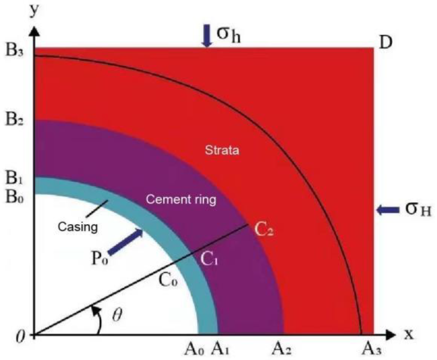
4.1. Finite Element Simulation of Casing Damage Well under Non-Uniform In-Situ Stress

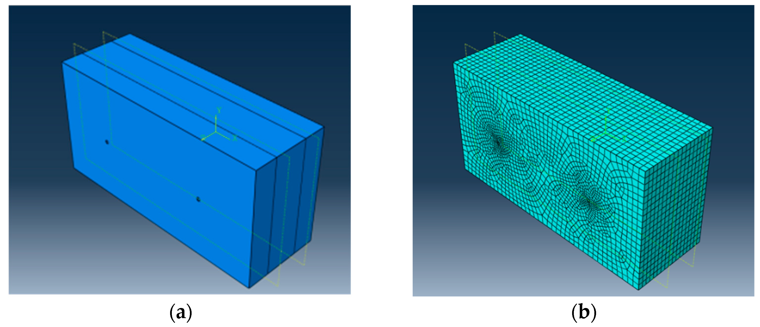
4.1.1. Establishment of a Casing Cement Sheath Formation Combination Model

According to the on-site data of the G155 block, the damaged wells were selected as the X1 well and X2 well, corresponding to the damaged well sections 1470–1915 m and 1800–2040 m; the influence of the formation boundary exceeding five to six times the wellbore radius on the stress around the wellbore is minimal. Therefore, the formation width is taken as 4 m, which is 20 times the wellbore diameter, to eliminate boundary effects. Considering the symmetry of the problem, take 1/4 for research. The established mechanical model of the casing cement sheath formation is shown in Figure 6, and the mechanical parameters are shown in Table 1. In the model, the A0B0 section is the inner wall of the casing, which is subjected to a liquid column pressure of P0 during production. The A0A3 and B0B3 edges are constrained by symmetrical displacement. The A3D section is subjected to horizontal forces σH, while the B3D section is subjected to horizontal forces σh. If σH = σh, the formation is subjected to uniform loads; otherwise, it is subjected to non-uniform loads.

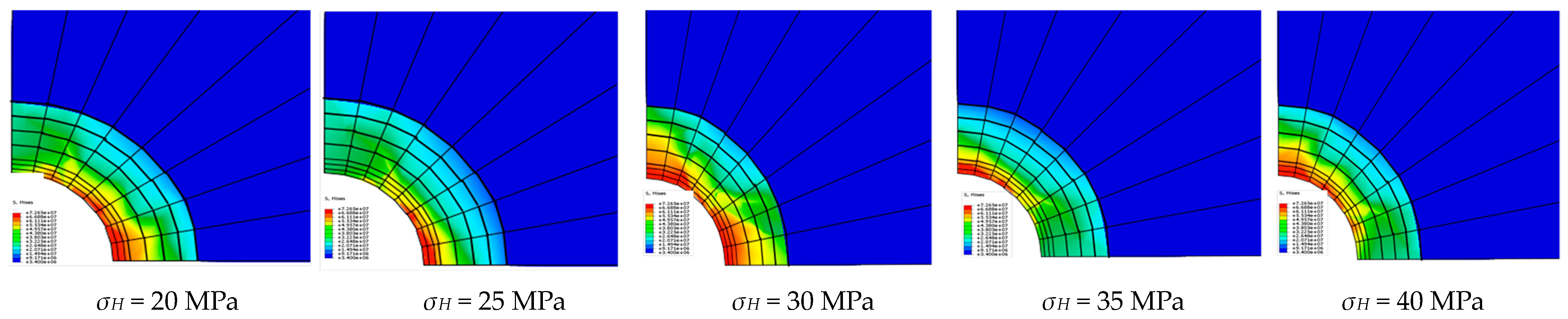
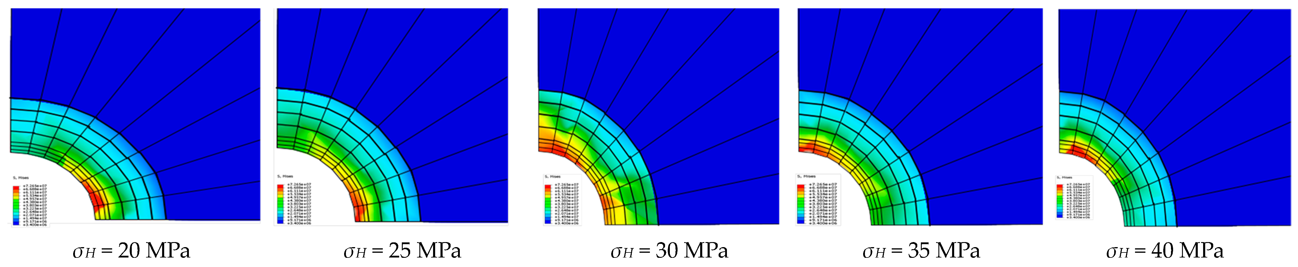
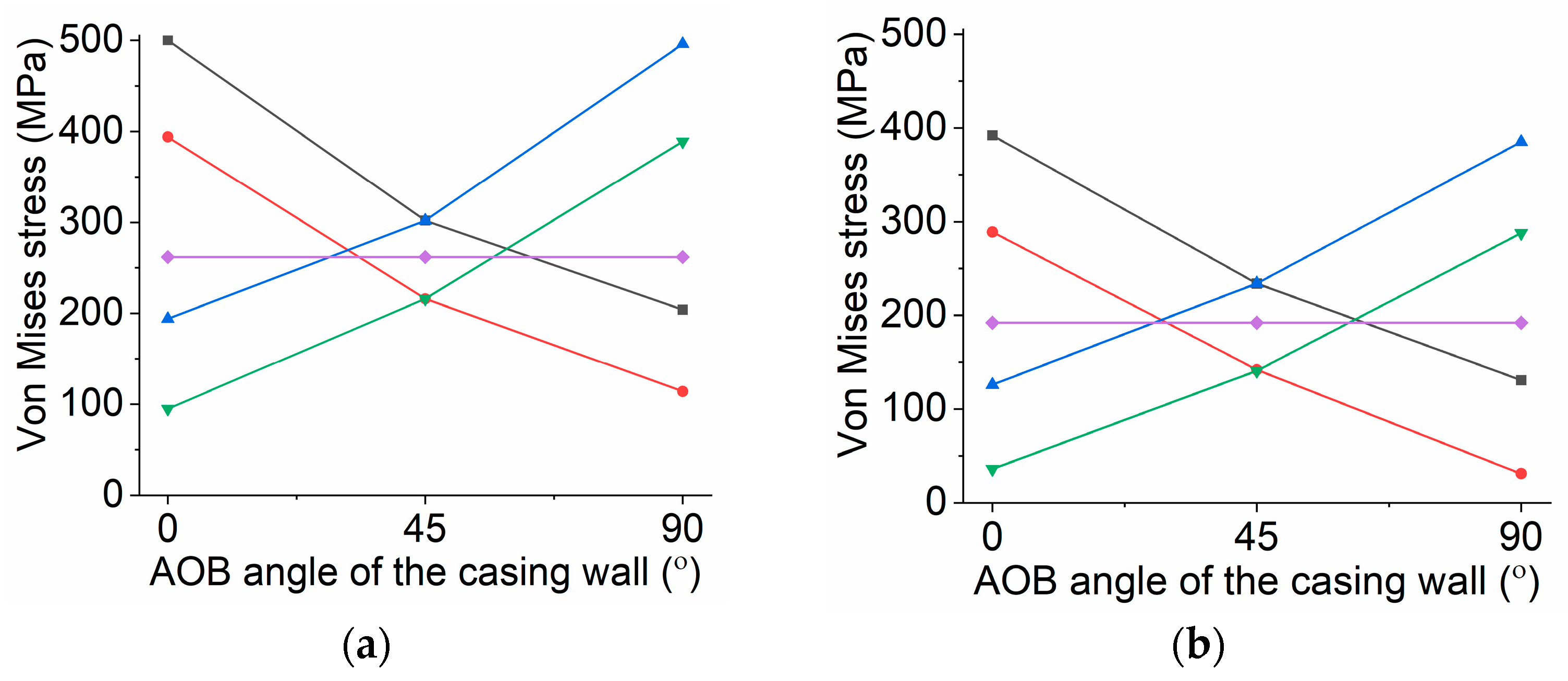
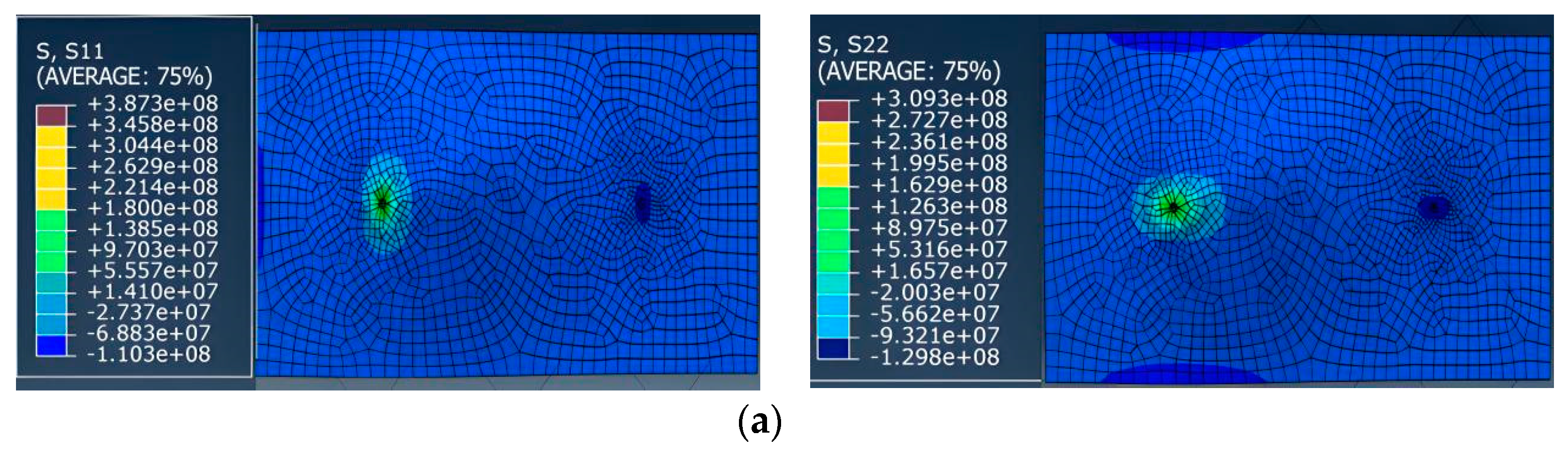
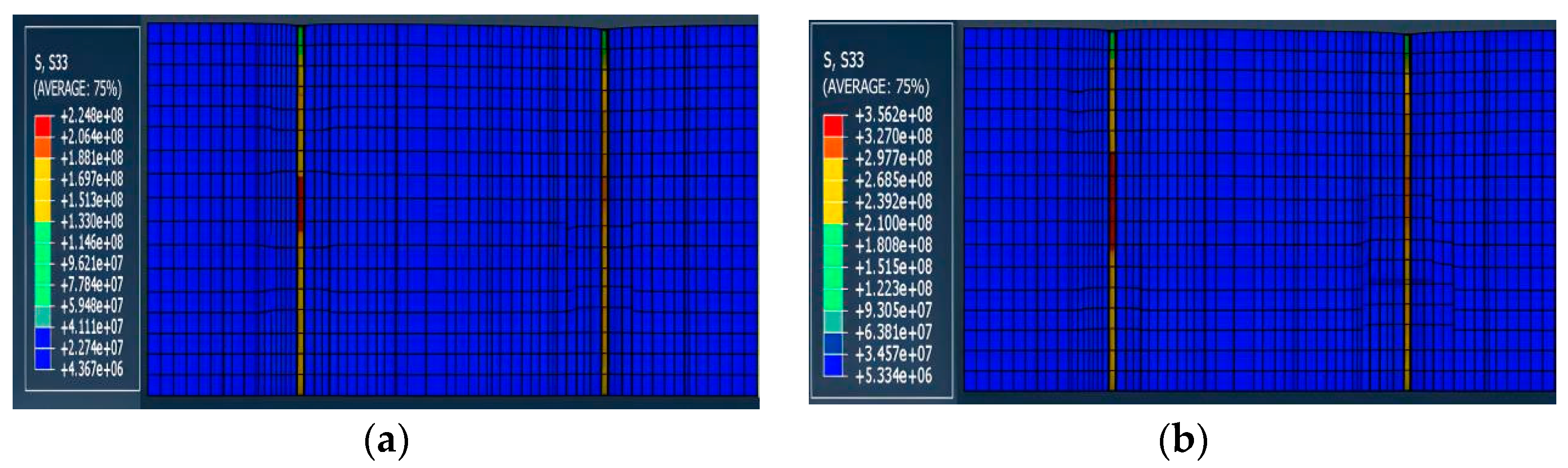
4.1.2. Von Mises Stress Analysis of Casing

In order to study the effect of different loads on the casing damage, it is taken as σh = 30 MPa, σH = 20–40 MPa. For the yield failure of materials, the Von Mises yield criterion is generally used. Therefore, when analyzing casing failure, the Von Mises stress of the inner wall is extracted for research. Figure 7, Figure 8 and Figure 9 show the Von Mises stress cloud and curve of the inner wall of the casing simulated at 20 MPa, 25 MPa, 30 MPa, 35 MPa, and 40 MPa for the X1 and X2 wells, with 0° representing the A0 point of the mechanical model and 90° representing the B0 point.
When σH = 20–30 MPa, the maximum Von mises stress is at point A0; the larger σH is, the smaller is the maximum Von Mises stress. When σHσh, the maximum Von mises stress is the smallest, and the Von Mises stress at each point on the inner wall of the casing is equal; When σH = 30–40 MPa, the maximum Von mises stress is at point B0 and the larger σH is, the greater is the maximum Von Mises stress.
For the X1 well, when σH is 20 MPa and 40 MPa, the maximum Von Mises stress of the casing will exceeds its yield limit and deforms, which is consistent with the casing damage situation in this area. For the X2 well, when σH is between 20 and 40 MPa, the Von Mises stress on the inner wall of the casing will not exceed its yield limit, meaning there will be no casing damage. The actual casing damage occurred in the well, indicating that the well is affected by other additional load factors.

4.2. Von Mises Stress Analysis of Casing under Mudstone Creep

4.2.1. Selection of Creep Model

Due to the presence of some hydrophilic clay minerals in the interstitial material of the reservoir in this block, as the injection and production parameters increase, the water content of the reservoir increases, and the clay minerals hydrate, causing rock sliding, compression, and shear of the casing. Therefore, it is necessary to analyze the stress on the casing under water immersion of the mudstone.
Mudstone undergoes elastic deformation after compression, and its elastic modulus decreases when encountering water. Therefore, its elastic modulus is inversely proportional to its water content; Afterwards, the creep of mudstone reaches a steady-state creep process, and its deformation will gradually increase. Therefore, the creep of mudstone when encountering water should contain elastic and viscous elements, so the Maxwell model is mostly used to represent the creep of mudstone, and the constitutive expression is shown in Equation (17):
  ε = σ E e a w + σ N η t e ω ω 0 1
In the equation, ω is the water content of mudstone (%); ω0 is the saturated water content of mudstone under geological conditions (%); E, η, a is the rheological parameter of the rock; N is the non-linear index.
Although the Maxwell model can describe the creep process of mudstone with water content, it cannot reflect the transitional stage of the mudstone creep process. Therefore, the Maxwell model has defects. In the later stage, the Maxwell model was modified and improved by adding a component related to water content to the component, as shown in Figure 10. If the water content of mudstone exceeds the natural water content in the formation, the elastic modulus and compressive strength of the mudstone will change with changes in the water content, and its creep equation is:
  ε = σ 0 η t + c ,   σ ω 0 < σ ω ε = σ 0 E e a w 1 exp E η 1 ω ω 0 a w ,   σ ω 0 σ ω
where w is the water content of mudstone in a stable state (%).

4.2.2. Finite Element Analysis of Casing under Mudstone Creep

  • Establishment of finite element model
Select one oil production well and one water injection well in the G155 block, with a model length of 300 m, width of 100 m, and height of 100 m. Considering the influence of structural morphology and water injection pressure on the casing, study the variation characteristics of the casing bearing stress under different injection production ratios. The finite element model established using ABAQUS is shown in Figure 11, and the mechanical parameters are shown in Table 2 and Table 3. The model consists of 28,365 elements and 18,933 nodes, including 15,749 octahedral elements with eight nodes.
2.
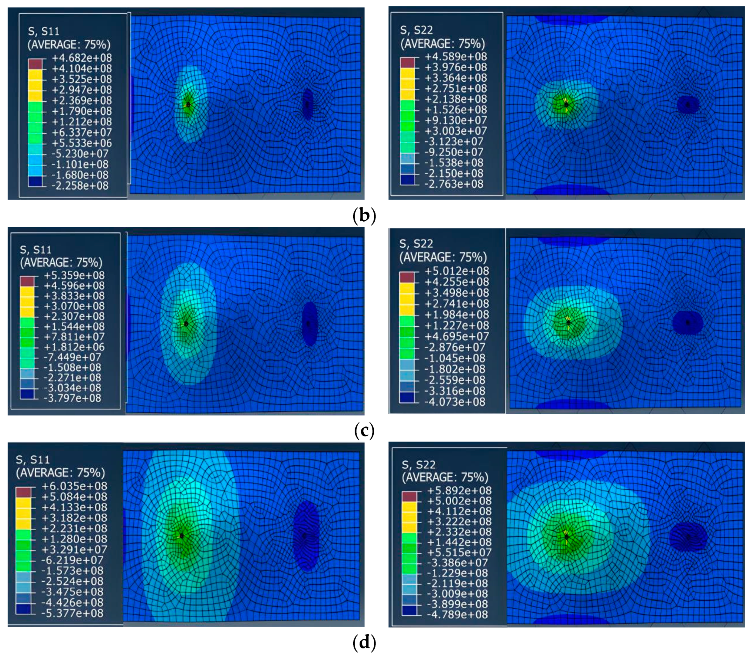
Normal stress analysis
In the process of oilfield water injection development, an increase in the injection production ratio means that the formation absorbs more water while the produced liquid is less, resulting in an imbalance between injection and production. At the same time, a large amount of injected water infiltrates the mudstone layer, causing it to creep and further exacerbating the damage to the casing. In oilfield development, the normal stress experienced by the casing represents the horizontal tension or compression of the casing. Due to the presence of non-uniform ground stress in underground rock layers, the normal stress around the casing exhibits a non-uniform elliptical distribution, which can be approximated by a cosine function. As the stress gradually increases and exceeds the yield limit of the casing, it will cause deformation and damage to the casing. The variation pattern of the normal stress contour under different injection production ratios is shown in Figure 12. From the graph, it can be seen that S11 is the normal stress in the X-axis direction, and S22 is the normal stress in the Y-axis direction. The normal stress in the S11 direction is significantly greater than that in the S22 direction. This is because the casing has undergone necking deformation, and the X-axis direction is the short axis of the ellipse, with a large amount of deformation and resulting stress. Comparing the stress cloud trends of oil wells and water wells, it can be seen that the normal stress of the oil well casing is greater than that of the water well casing. Therefore, the oil well needs to break before the water well. At the same time, as the injection production ratio increases, the normal stress on the casing gradually increases.
3.
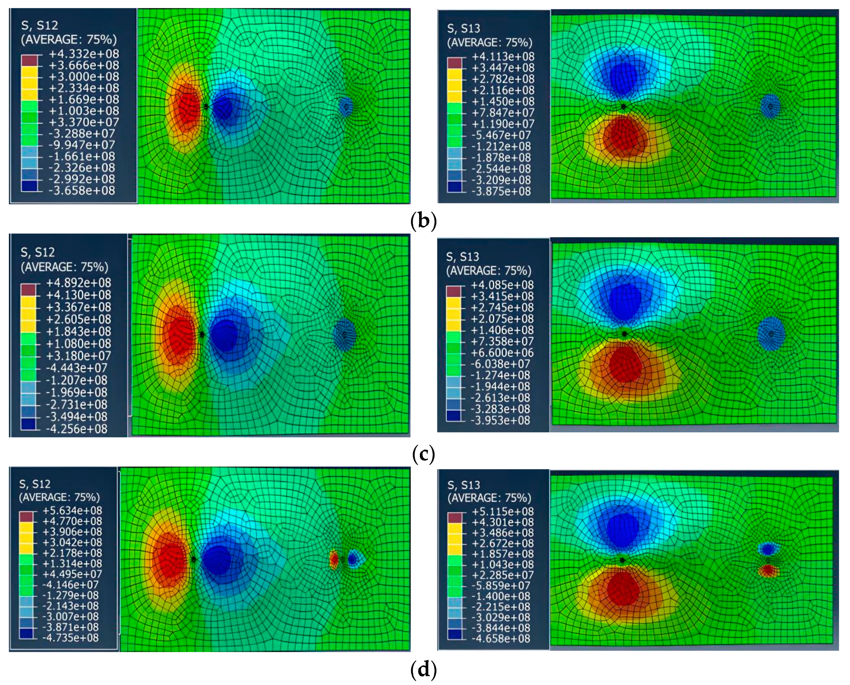
Shear stress analysis
Due to the injection of water entering the mudstone layer along the perforation section or corresponding layer fractures, mudstone creep occurs, while the strength changes in the non-mudstone layer after encountering water are different from that of the mudstone layer. Therefore, a stress difference is formed between the mudstone layer and the non-mudstone layer, resulting in shear stress. We simulated the changes in shear stress borne by the casing under different injection production ratios, as shown in Figure 13. It can be seen that S12 is the shear stress in the X-axis direction, and S13 is the shear stress in the Y-axis. As the injection production ratio increases, the water content of the reservoir increases, and the shear stress generated by the creep force on the casing increases. When the injection production ratio is greater than 1.3, the shear force on the oil well casing exceeds the yield limit of the casing, causing the casing to gradually undergo shear deformation. When the injection production ratio is 1.9, shear stress also begins to appear near the water well, exceeding the yield limit of the casing and causing deformation.
4.
Vertical stress analysis
Vertical stress indicates that when water infiltrates the mudstone layer, it not only undergoes creep, but also expands, causing the formation to rise and causing damage to the casing due to the stretching of the rock layer. The vertical stress contour under different injection production ratios is shown in Figure 14, which can reflect the stress variation of the casing when it is stretched by the rock layer after mudstone expansion. It can be seen that as the injection production ratio increases, the vertical stress S33 on the casing gradually increases. When the injection production ratio is greater than 1.6, the vertical stress on the casing exceeds its yield limit, and the casing gradually undergoes longitudinal tensile deformation.
5.
Von Mises stress analysis
The Von Mises stress of the casing represents the comprehensive reflection of the additional external extrusion load borne by the casing. Figure 15 simulates the variation curves of the formation water content and equivalent stress of three types of wall thickness casings under different injection production ratios. Among them, an increase in water content represents an extension of water injection development time and an increase in formation water absorption. From Figure 15, it can be seen that with the extension of the mining time, the equivalent stress borne by the casing gradually increases when the wall thickness of the casing is 7.72 mm, 9.17 mm, and 10.54 mm, respectively, and the Von Mises stress increases with the increase in the injection production ratio. When the injection production ratio is greater than 1.3, the shear force gradually compresses and deforms the oil well casing. When the injection production ratio is greater than 1.6, the casing is longitudinally stretched and deformed; the injection production ratio is 1.9, and shear stress occurs near the water well, exceeding the yield limit of the casing and causing deformation. Under different injection production ratios and wall thickness conditions, the variation law of Von Mises stress inside the casing is consistent, and with the extension of the mining time, the Von Mises stress borne by the casing gradually increases. However, after reaching the yield limit, the Von Mises stress inside the casing no longer changes, and under the same wall thickness conditions, the Von Mises stress borne by the casing increases with the increase in the injection production ratio. Therefore, there is a significant correlation between the injection production ratio and the equivalent stress borne by the casing.
The increase in the injection production ratio means that the formation absorbs more water, while the amount of extracted liquid is less, resulting in an imbalance between injection and extraction. At the same time, a large amount of injected water infiltrates the mudstone layers, exacerbating their creep. Therefore, reasonable control of injection production ratio is not only beneficial for development technology policies, but also can effectively extend the service life of the casing. In addition, comparing the Von Mises stress of the casing under three different wall thicknesses, it was found that the Von Mises stress of the 7.72 mm wall thickness casing was significantly greater than that of the 10.54 mm wall thickness casing. From the perspective of the bearing stress capacity of the casing, increasing the wall thickness appropriately can effectively delay the deformation and damage time of the casing.

5. Conclusions

This study categorized, statistically analyzed, and described the present casing damage scenario in the concentrated G155 block. A finite element numerical model was devised to examine stress levels in damaged well casings within this region. The ensuing conclusions are detailed below:
(1)
Based on the calculation of typical single well fracturing data and the application of the in-situ stress inversion method, the structural stress coefficient of the study area is derived, and the maximum and minimum horizontal in-situ stress calculation formulas are obtained. Theoretical stress analysis is conducted on casing-damaged wells under uniform and non-uniform conditions.
(2)
According to the finite element analysis of the casing of X1 and X2 wells under non-uniform in-situ stress conditions at σh = 30 MPa and σH = 20–40 MPa, it can be concluded that the reasons for casing damage in the study area are not only non-uniform in-situ stress but also some other creep additional loads.
(3)
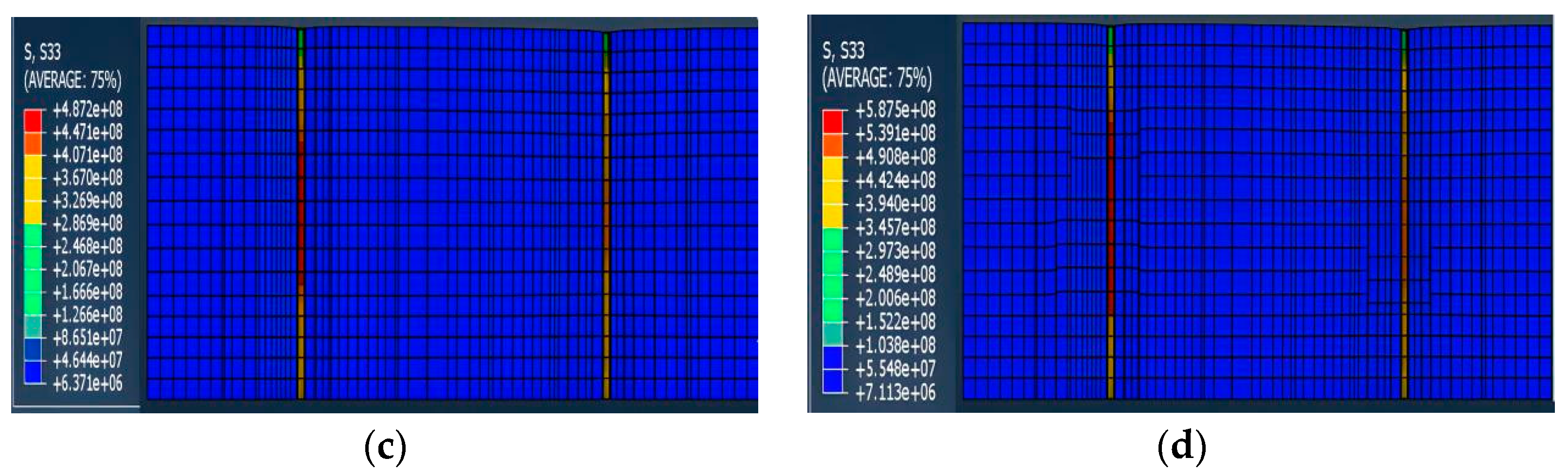
Finite element analysis of casing subjected to mudstone creep revealed increased shearing and deformation post-water immersion, causing premature oil well failure over water wells. The equivalent force rose with higher injection production ratios. Ratios above 1.3 led to gradual compression and deformation, exceeding the yield limit, while ratios over 1.6 induced longitudinal stretching. At a ratio of 1.9, shear stress near water wells surpassed the casing’s yield limit, resulting in deformation.
The final Von Mises stress in the G155 block is influenced not only by the injection production ratio but also by pore pressure, permeability, and water injection pressure. Key mechanical factors contributing to casing damage are horizontal in-situ stress and mudstone creep.

Author Contributions

Conceptualization, T.W. and J.S.; methodology, M.L., N.L. and T.Z.; formal analysis, T.W.; investigation, T.W., N.L. and J.S.; resources, T.Z.; data curation, M.L. and N.L.; writing—original draft preparation, T.W. and M.L.; writing—review and editing, T.Z. and J.S.; supervision, J.S.; funding acquisition, T.W. and J.S. All authors have read and agreed to the published version of the manuscript.

Funding

This work is supported by the National Natural Science Foundation of China (No. 42141011) and the National Science and Technology Major Project during the 13th Five Year Plan (No. 2017ZX05013-005).

Institutional Review Board Statement

Not applicable.

Informed Consent Statement

Not applicable.

Data Availability Statement

The data that support the findings of this study are available from the corresponding author upon reasonable request.

Acknowledgments

We would like to sincerely acknowledge the National Engineering Laboratory for Exploration and Development of the Low Permeability Oil and Gas Field for providing experimental conditions and instruments.

Conflicts of Interest

Authors Tianjiang Wu, Mei Li, Nana Liu and Tao Zhang were employed by the company China National Petroleum Corporation. The remaining author declare that the research was conducted in the absence of any commercial or financial relationships that could be construed as a potential conflict of interest.

References

  1. Li, F.; Tang, Q.; Yan, W.; Li, J.; Li, W.; Yang, T.; Lin, L.; Jiang, K.; Wang, K.; Zhang, W. Research on the failure analysis and prediction method of casing deformation under the synergistic effect of sand production and corrosion. Eng. Fail. Anal. 2023, 154, 107706. [Google Scholar] [CrossRef]
  2. Rodríguez, V.; Guerrero, H.; Alcocer, S.M.; Tapia-Hernández, E. Rehabilitation of heavily damaged beam-column connections with CFRP wrapping and SFRM casing. Soil Dyn. Earthq. Eng. 2021, 145, 106721. [Google Scholar] [CrossRef]
  3. Kyogoku, T.; Tokimasa, K.; Nakanishi, H.; Okazawa, T. Experimental Study on the Effect of Axial Tension Load on the Collapse Strength of Oilwell Casing. Soc. Pet. Eng. J. 1982, 22, 609–615. [Google Scholar] [CrossRef]
  4. Lei, W.; Li, Q.; Yang, H.; Wu, T.; Wei, J.; Wang, M. Preferential flow control in heterogeneous porous media by concentration-manipulated rheology of microgel particle suspension. J. Pet. Sci. Eng. 2022, 212, 110275. [Google Scholar] [CrossRef]
  5. El-Sayed, A.A.H.; Khalaf, F. Resistance of cemented concentric casing strings under nonuniform loading. SPE Drill. Eng. 1992, 7, 59–64. [Google Scholar] [CrossRef]
  6. Xu, B.; Zhang, Y.; Wang, H.; Yin, H.; Jia, T. Application of numerical simulation in the solid expandable tubular repair for casing damaged wells. Pet. Explor. Dev. 2009, 36, 651–657. [Google Scholar]
  7. Dusseault, M.B.; Bruno, M.S.; Barrera, J. Casing Shear: Causes, Cases, Cures. SPE Drill. Compl. 2001, 16, 98–107. [Google Scholar] [CrossRef]
  8. Yan, Y.; Cai, M.; Ma, W.; Zhang, X.; Han, L.; Liu, Y. Research on casing deformation prevention technology based on cementing slurry system optimization. Pet. Sci. 2024, 21, 1231–1240. [Google Scholar] [CrossRef]
  9. Boade, R.R.; Chin, L.Y.; Siemers, W.T. Forecasting of Ekofisk reservoir compaction and subsidence by numerical simulation. J. Pet. Technol. 1989, 41, 723–728. [Google Scholar] [CrossRef]
  10. Nordsveen, M.; Nešic, S.; Nyborg, R.; Stangeland, A. A mechanistic model for carbon dioxide corrosion of mild steel in the presence of protective iron carbonate films—Part 1: Theory and Verification. Corrosion 2003, 59, 443–456. [Google Scholar] [CrossRef]
  11. Kermani, M.B.; Morshed, A. Carbon dioxide corrosion in oil and gas production—A compendium. Corrosion 2003, 59, 659–683. [Google Scholar] [CrossRef]
  12. Lei, W.; Lu, X.; Liu, F.; Wang, M. Non-monotonic wettability effects on displacement in heterogeneous porous media. J. Fluid Mech. 2022, 942, R5. [Google Scholar] [CrossRef]
  13. Wang, H.; Zhao, W.; Shu, Z.; Zhao, Q.; Han, L. Failure analysis of casing dropping in shale oil well during large scale volume fracturing. Eng. Fail. Anal. 2020, 118, 104849. [Google Scholar] [CrossRef]
  14. Yan, W.; Zou, L.; Li, H.; Deng, J.; Ge, H.; Wang, H. Investigation of casing deformation during hydraulic fracturing in high geo-stress shale gas play. J. Pet. Sci. Eng. 2017, 150, 22–29. [Google Scholar] [CrossRef]
  15. Lian, Z.; Yu, H.; Lin, T.; Guo, J. A study on casing deformation failure during multi-stage hydraulic fracturing for the stimulated reservoir volume of horizontal shale wells. J. Nat. Gas Sci. Eng. 2015, 23, 538–546. [Google Scholar] [CrossRef]
  16. Peng, S.; Fu, J.; Zhang, J. Borehole casing failure analysis in unconsolidated formations: A case study. J. Pet. Sci. Eng. 2007, 59, 226–238. [Google Scholar] [CrossRef]
  17. Gholami, R.; Rasouli, V.; Aadnoy, B.; Mohammadnejad, M. Geomechanical and numerical studies of casing damages in a reservoir with solid production. Rock Mech. Rock Eng. 2016, 49, 1441–1460. [Google Scholar] [CrossRef]
  18. Ispas, I.; Bray, A.R.; Palmer, I.D.; Higgs, N.G. Prediction and evaluation of sanding and casing deformation in a GOM-Shelf well. J. Pet. Technol. 2005, 57, 75–78. [Google Scholar] [CrossRef]
  19. Wagg, B.; Xie, J.; Solanki, S.; Arndt, S. Evaluating casing deformation mechanisms in primary heavy oil production. In Proceedings of the 1999 SPE International Thermal Operations and Heavy Oil Symposium, Bakersfield, CA, USA, 17–19 March 1999. [Google Scholar]
  20. Yin, F.; Han, L.; Yang, S.; Deng, Y.; He, Y.; Wu, X. Casing deformation from fracture slip in hydraulic fracturing. J. Pet. Sci. Eng. 2018, 166, 235–241. [Google Scholar] [CrossRef]
  21. Liu, W.; Zhang, Z.; Chen, J.; Fan, J.; Jiang, D.; Daemen, J.; Li, Y. Physical simulation of construction and control of two butted-well horizontal cavern energy storage using large molded rock salt specimens. Energy 2019, 185, 682–694. [Google Scholar] [CrossRef]
  22. Cornet, J.S.; Dabrowski, M.; Schmid, D.W. Long term creep closure of salt cavities. Int. J. Rock Mech. Min. Sci. 2018, 103, 96–106. [Google Scholar] [CrossRef]
  23. Furui, K.; Fuh, G.F.F.; Morita, N. Casing- and screen-failure analysis in highly compacting sandstone fields. SPE Drill. Compl. 2012, 27, 241–252. [Google Scholar] [CrossRef]
  24. Singh, A.; Kumar, C.; Kannan, L.G.; Rao, K.S.; Ayothiraman, R. Estimation of creep parameters of rock salt from uniaxial compression tests. Int. J. Rock Mech. Min. Sci. 2018, 107, 243–248. [Google Scholar] [CrossRef]
  25. Ewy, R.T. Wellbore-Stability Predictions by use of a modified lade criterion. SSPE Drill. Compl. 1999, 14, 85–91. [Google Scholar] [CrossRef]
  26. Shen, X.; Zhang, P. A calculation method for the allowable fracturing injection pressure of preventing casing deformation. Nat. Gas Ind. B 2019, 6, 384–393. [Google Scholar] [CrossRef]
  27. Ciarlet, P.G. The Finite Element Method for Elliptic Problems; Society for Industrial and Applied Mathematics: Philadelphia, PA, USA, 2002. [Google Scholar]
  28. Dell’Accio, F.; Di Tommaso, F.; Guessab, A.; Nudo, F. Enrichment strategies for the simplicial linear finite elements. Appl. Math. Comput. 2023, 451, 128023. [Google Scholar] [CrossRef]
  29. Xi, Y.; Li, J.; Liu, G.; Tao, Q.; Lian, W. A new numerical investigation of cement sheath integrity during multistage hydraulic fracturing shale gas wells. J. Nat. Gas Sci. Eng. 2018, 49, 331–341. [Google Scholar]
  30. Xi, Y.; Li, J.; Liu, G.; Cha, C.; Fu, Y. Numerical investigation for different casing deformation reasons in Weiyuan-Changning shale gas field during multistage hydraulic fracturing. J. Nat. Gas Sci. Eng. 2018, 163, 691–702. [Google Scholar] [CrossRef]
  31. Deng, K.; Xie, P.; Yue, Y.; Zeng, D.; Li, Q.; Lin, Y. Study on the effect of interface failure between casing and cement sheath on casing stress under non-uniform in-situ stress. Appl. Math. Model. 2021, 92, 632–652. [Google Scholar]
  32. Mohammadnejad, T.; Khoei, A.R. An extended finite element method for hydraulic fracture propagation in deformable porous media with the cohesive crack model. Finite Elem. Anal. Des. 2013, 73, 77–95. [Google Scholar] [CrossRef]
  33. Zhang, Z.; Shao, L.; Zhang, Q.; Zhang, C.; Li, J.; Zeng, D.; Zhong, X.; Hu, J.; Hou, D.; Shi, T. Environmentally assisted cracking performance research on casing for sour gas wells. J. Pet. Sci. Eng. 2017, 158, 729–738. [Google Scholar]
  34. Meng, H.; Ge, H.; Yao, Y.; Shen, Y.; Wang, J.; Bai, J.; Zhang, Z. A new insight into casing shear failure induced by natural fracture and artificial fracture slip. Eng. Fail. Anal. 2022, 137, 106287. [Google Scholar] [CrossRef]
  35. Tong, K.; Zhao, J.; Liu, Q.; Zhu, B.; Jin, Q.; Qu, T.; Liu, Q.; Cong, S. Analysis and investigation of the leakage failure of a casing used in a shale gas well. Eng. Fail. Anal. 2022, 131, 105891. [Google Scholar] [CrossRef]
Figure 1. Classification of mechanical types of casing damage in the G155 block.
Applsci 14 05987 g001
Figure 2. Casing damage of production wells in the G155 block: (a,b) reflected by the lead imprint; (c) reflected by engineering logging.
Applsci 14 05987 g002
Figure 3. Distribution of casing damage wells in different layers of the G155 block.
Applsci 14 05987 g003
Figure 4. Service life of G155 block casing damaged wells.
Applsci 14 05987 g004
Figure 5. Distribution of in-situ stress at horizontal section.
Applsci 14 05987 g005
Figure 6. Finite element model of mechanical model.
Applsci 14 05987 g006
Figure 7. Stress distribution of the casing under non-uniform in-situ stress in X1 well.
Applsci 14 05987 g007
Figure 8. Stress distribution of the casing under non-uniform in-situ stress in X2 well.
Applsci 14 05987 g008
Figure 9. Von Mises stress curve of (a) X1 well and (b) X2 well.
Applsci 14 05987 g009
Figure 10. Structural diagram of water containing components.
Applsci 14 05987 g010
Figure 11. Three-dimensional finite element model. (a) Geometry structure, (b) Mesh structure.
Applsci 14 05987 g011
Figure 12. Normal stress contour at different injection rates (left: maximum horizontal normal stress component; right: minimum horizontal normal stress component): (a) 1.0; (b) 1.3; (c) 1.6; (d) 1.9.
Applsci 14 05987 g012aApplsci 14 05987 g012b
Figure 13. Shear stress contour at different injection rates (left: maximum horizontal normal stress component; right: minimum horizontal normal stress component): (a) 1.0; (b) 1.3; (c) 1.6; (d) 1.9.
Applsci 14 05987 g013aApplsci 14 05987 g013b
Figure 14. Vertical stress contour at different injection production ratios: (a) 1.0; (b) 1.3; (c) 1.6; (d) 1.9.
Applsci 14 05987 g014aApplsci 14 05987 g014b
Figure 15. Von Mises stress curve of J55 casing at different injection production ratios: (a) 1.0; (b) 1.3; (c) 1.6; (d) 1.9.
Applsci 14 05987 g015
Table 1. Mechanical parameters of casing cement sheath formation.
Media TypeElastic Modulus,
E (104 MPa)
Poisson Ratio, μ (-)Density,
ρ (g/cm3)
Cohesion,
τ (MPa)
Internal Friction Angle, φ (°)
Casing21.20.307.8//
Cement sheath3.20.232.4924
Sandstone1.320.252.21028
Table 2. Material parameters.
Media TypeDensity
(g/cm3)
Elastic Modulus
(104 Mpa)
Poisson Ratio
(-)
Casing7.821.20.30
Cement sheath2.43.20.23
Sandstone2.21.320.25
Mudstone2.50.210.24
Table 3. Process parameters of injection production ratio scheme.
Producing Pressure Difference (MPa)Injection Pressure
(MPa)
Injection-Production Ratio
1015.51.0
1015.51.3
1015.51.6
1015.51.9
Disclaimer/Publisher’s Note: The statements, opinions and data contained in all publications are solely those of the individual author(s) and contributor(s) and not of MDPI and/or the editor(s). MDPI and/or the editor(s) disclaim responsibility for any injury to people or property resulting from any ideas, methods, instructions or products referred to in the content.

