Article

Thermodynamic Study on the Vortex Teeth of Electric Scroll Compressors Based on Gradient Tooth Height

School of Automotive & Rail Transit, Nanjing Institute of Technology, Nanjing 211167, China
*
Authors to whom correspondence should be addressed.
Appl. Sci. 2024, 14(14), 5977; https://doi.org/10.3390/app14145977
Submission received: 6 May 2024 / Revised: 6 July 2024 / Accepted: 8 July 2024 / Published: 9 July 2024

Abstract

:
Through the analysis of the adhesion between the tooth head and axial clearance leakage attributed to vortex tooth shape deformation, an innovative tooth shape design concept has been introduced entitled “progressive change tooth high vortex tooth”. This unique design includes a gradual change in tooth height and an elevated vortex tooth profile, using temperature-sensitive materials to enhance the resolution of temperature loading on the vortex disc. By refining the process of resolving the temperature loading on the vortex disc, the mean temperature function of the fluid domain along the wall of the vortex tooth is calculated, and a steady-state temperature distribution model for the solid domain of the vortex tooth is formulated. Subsequently, a finite element model for the high eddy current disc is constructed using Abaqus 2021 finite element software, which facilitates the calculation of stress–strain distribution within the high eddy current disc under both gas pressure and temperature field loads. The results show that, especially under conditions of low speed and low exhaust pressure, the temperature load mainly influences the maximum deformation and stress distribution of the vortex tooth. Specifically, under the influence of heat-solid coupling, the maximum deformation of the progressive change tooth high vortex tooth occurs in close proximity to the central compression cavity, reaching up to 13 microns. These results provide a crucial theoretical basis for the structural design and performance optimization of the compressor.

1. Introduction

A scroll compressor, also known as a centrifugal compressor, is an instrument that is used to compress gases or gas mixtures. Its operation is based on the use of centrifugal force to expel gases while simultaneously generating increased pressure through the rotation process. This ingenious configuration of the scroll compressor allows it to maintain high levels of efficiency while maintaining its compact dimensions. Typically, scroll compressors exhibit superior capacity for flow rates and compression ratios compared to other compressor types.
Throughout the operation of a scroll compressor, dynamic and static scroll discs are subjected to various forces, including gas pressure, thermal stresses due to non-uniform temperature distributions, inertial forces acting on the dynamic discs, and compressive forces during the engagement of scroll teeth. These forces cause deformation in the dynamic scroll disc, which affects the efficiency and reliability of the scroll compressor [1,2,3]. Therefore, the performance and dependability of the scroll compressor are significantly affected by these forces.
Recently, researchers have been actively investigating the stress–strain behaviors of a moving vortex disc under varying conditions by using gas pressure and temperature as key parameters [4,5]. Liu et al. [6,7,8] conducted comprehensive analyses considering temperature fluctuations and the periodic changes of convective heat transfer coefficients during the compression stages of scroll compressors. Their study aimed to optimize the performance of scroll compressors, enhance operational efficiency, and improve the accuracy of temperature distribution predictions under various operating conditions, thus laying a foundation for the optimal design of such compressors. Li et al. [9] addressed issues related to pre-compression phenomena and flow field characteristics by establishing a model and conducting simulations to elucidate the mechanisms and influencing factors associated with pre-compression phenomena. In addition, finite element analyses were carried out to investigate the forces and deformations experienced by scroll discs, refine solutions for temperature loads, and explore the effects of multiple loads on the stress–strain characteristics of scroll teeth. Hirano et al. [10] created perfect meshing profile (PMP) scroll profiles that feature minimal clearance volume at the discharge end. The researchers also carried out theoretical and experimental investigations to assess the internal stress, efficiency, and noise levels of the scroll compressor equipped with a PMP profile. Meng et al. [11] utilized Ansys 2020 simulation software to analyze the deformation and stress distribution of two scroll teeth in a meshing state, taking into account gas force, temperature, inertial constraints, and multi-field coupling loads. Results indicate a significant influence of the temperature load field on tooth deformation. The presence of coupled loads led to noticeable deformation at the apex of the stationary vortex tooth, and the highest stress concentration was at the base of the moving vortex tooth. Additionally, maximum stress in the coupled field does not result from a simple summation of stresses from individual loads. Through numerical simulations, Li et al. [12] analyzed transient flows, taking into account factors such as clearances and rotational speeds. The results indicate that higher speeds lead to increased pressure fluctuations and overcompression, highlighting the importance of scroll seal design, especially at the compressor’s starting part, for optimal performance. Ballani et al. [13] developed a novel hybrid time-scale heat transfer method for modeling the effect of thermal load on compressor performance. Cavazzini et al. [14] utilized computational fluid dynamics (CFD) software CFX 19.0 and different axial clearance modeling approaches to study the internal flow dynamics of a compressor through numerical simulations. Wang et al. [15] conducted numerical simulations focusing on gas flow characteristics during the working process of scroll compressors. Through simulations, pressure, and temperature field distributions were obtained and used as boundary conditions for force and deformation calculations of scroll teeth. Wu et al. [16] established a three-dimensional numerical model of flow fields with dynamic and static scroll disc meshing, successfully capturing dynamic distribution patterns of flow field parameters within scroll compressor working chambers through comparison with experimental results.
To summarize, current scholars usually adopt loading methods such as linear temperature loading, average temperature loading, and interpolation of flow field wall temperature data for the study of scroll disc stress and strain, but these methods have obvious deviations from the actual temperature distribution. In order to study the heat transfer characteristics of the scroll disc more accurately, this study improves the solution method of the scroll disc temperature load, adopts the nonlinear distribution to deal with the temperature load, and, according to the characteristics of the temperature distribution of the fluid domain at different scroll tooth profile expansion angles, solves the temperature distribution function of the fluid domain on the wall surface of the scroll tooth at the corresponding profile expansion angle (which is closer to the instantaneous temperature change of the fluid domain of the compression chamber contact at different profile expansion angles). The temperature distribution function of the solid domain of the scroll tooth is obtained from the convective heat transfer equation.
In addition, by combining the gas pressure distribution characteristics of the inner and outer working cavities of the movable scroll teeth and the rotational, translational characteristics of the movable scroll disc, the stress–strain conditions of the asymptotic tooth high scroll teeth under nonlinear temperature loading and gas force loading, as well as the coupling of the two, are investigated based on Abaqus 2021 finite element software, in order to determine the optimal range of the asymptotic tooth height for asymptotic tooth high scroll discs in cast iron materials. These works will help to better understand and optimize the performance of scroll compressors.

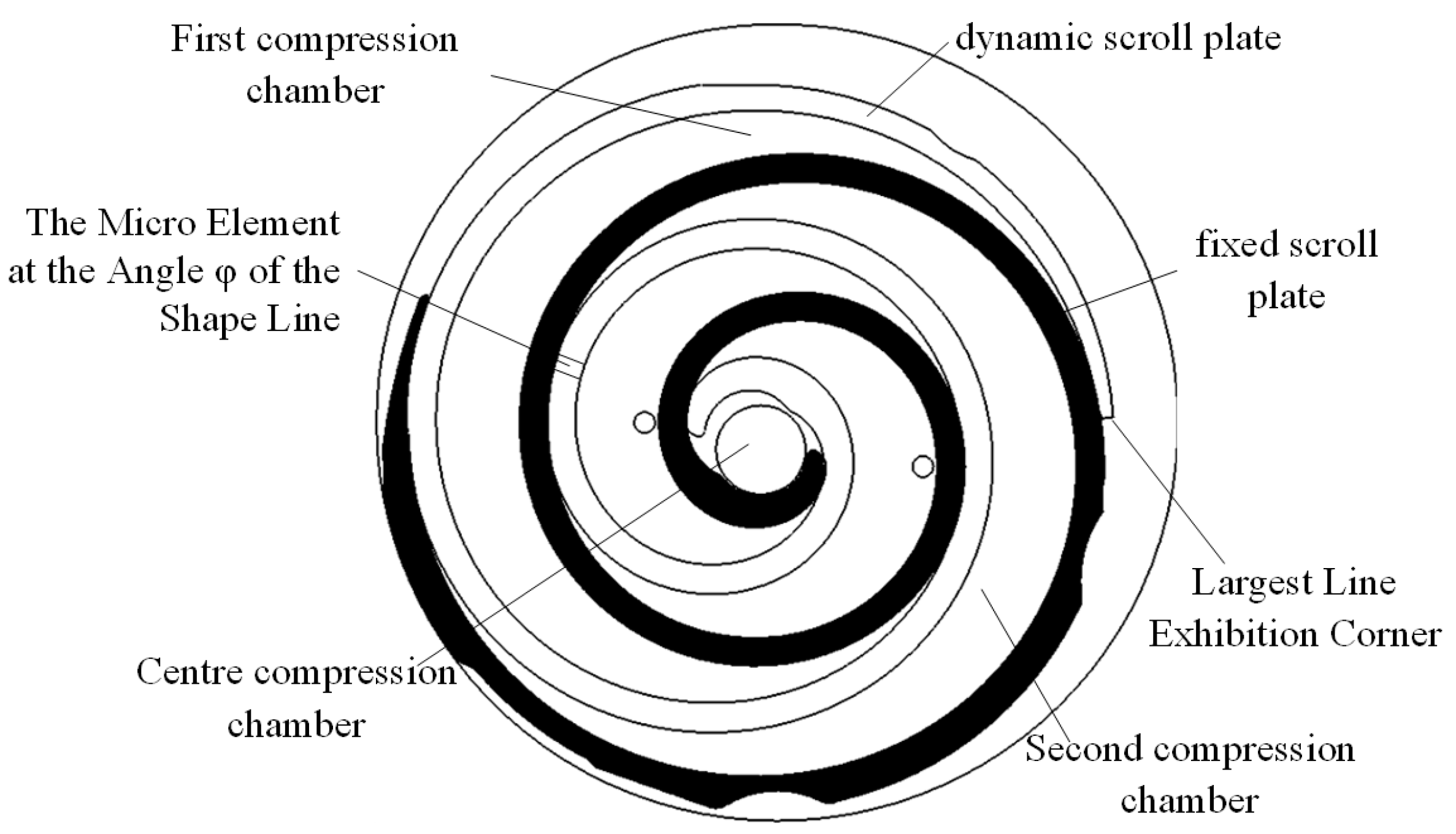
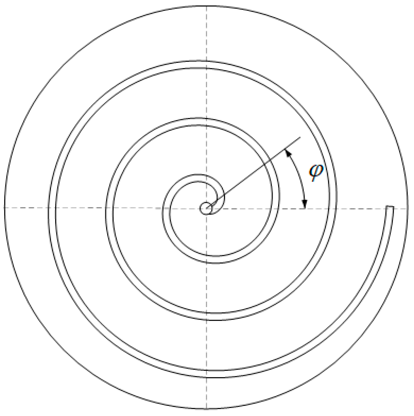
2. Vortex Tooth Temperature Distribution Model

2.1. Model Analysis and Assumptions

In power systems, a scroll compressor is an essential component whose functionality is intricately linked to complex thermodynamic and heat transfer phenomena. The operation of the scroll compressor relies heavily on the dynamic interaction between the scroll’s tooth walls and the gas, resulting in a finely tuned thermal conductivity process critical for heat exchange. In this operational context, the surface of the roller tooth walls acts as a heat transfer interface, facilitating the efficient transfer of thermal energy between the gas medium and the scroll teeth. The irregular distribution of gas temperature in the compression chamber, which is an important factor in the function of scroll compressors, was investigated. Three primary forms of heat transfer, including conduction along the profile direction, heat transfer across the tooth height, and convective heat exchange along the tooth thickness, are present within the scroll tooth. Together, these modes of heat transfer synergistically influence the shape of heat distribution and temperature variation within the scroll tooth.
In this study, air was chosen as the working medium due to its practical simplification of the dynamic temperature distribution model of the vortex disc into a steady-state temperature distribution model. The following assumptions are made throughout the research:
(1)
The average gas temperature and the convective heat transfer coefficient associated with the scroll teeth are maintained throughout the operation cycle.
(2)
The focus is exclusively on the change in temperature distribution along the profile axis.
(3)
The influence of spindle rotation speed fluctuations on temperature distribution has been ignored, assuming that it remains constant.

2.2. Steady-State Temperature Function of the Wall Surface of the Vortex Tooth

Under conditions of operational stability, the temperature distribution across the scroll teeth undergoes discernible fluctuations due to cyclical interaction with the working gas, showing a periodic variation. At present, in a stable operating state for the scroll compressor, where the rotational speed of the main shaft is increased, the pace of temperature oscillations also accelerates. Accordingly, the operating dynamics of the scroll compressor can be conceptualized as an adiabatic process, a concept expressible by the following Equation (1):
T = T s V s V θ K 1
where T is the temperature of the gas in the compression chamber when the crankshaft angle is θ ,   T S is the suction temperature, V s is the suction chamber volume, V ( θ ) is the volume of the compressor at crankshaft angle θ, and K is the adiabatic coefficient of the fluid medium. The fluid medium chosen in this paper is ideal air, with a value of 1.4.
The volume of the compression chamber at a given crankshaft rotation angle can be determined using Equation (2) [17].
V θ = π h R b 2 π 2 α 2 ϕ e 3 π 2 θ
where h is the tooth height of the scroll tooth, α is the volute profile involute generation angle, R b is the radius of the base circle, and   ϕ e is the maximum expansion angle of the profile.
The relationship between the temperature variation in the flow field on the inner and outer wall surfaces of the vortex teeth with respect to the crankshaft angle can be expressed by Equations (3) and (4), derived from Equations (1) and (2) as follows:
T g a s , i n θ = V s V θ K 1 · T S , θ 0 , ϕ e θ T d , θ ( ϕ e θ , ϕ e
T g a s , o u t θ = T s , θ 0 , π V s V θ K 1 · T S , θ π , ϕ e θ + π T d , θ ϕ e θ + π , ϕ e
The microelement positioned at the profile spreading angle φ of the vortex profile serves as the focal point of reference, as illustrated in Figure 1. Upon locating the microelement at the inner tangent point of the compression cavity, it is designated as the starting point. During the operational phase of the vortex disc, the microelement is configured to complete one cycle at a value of 2π.
Based on the specified conditions, it can be inferred that the microelement within a single working cycle, denoted as 2π, exhibits a mean temperature function across the flow field on the inner wall of the vortex tooth. This function is represented by Equation (5):
T ¯ g a s , i n φ = 1 2 π ϕ e φ ϕ e φ + 2 π T g a s , i n θ d θ
The boundary conditions for the outer wall of the vortex tooth exhibit a phase lag in relation to the alteration of boundary conditions on the inner side. Therefore, the average temperature of the outer gas over a single operating cycle can be mathematically represented as Equation (6):
T ¯ g a s , o u t φ = 1 2 π ϕ e φ π ϕ e φ + π T g a s , o u t θ d θ
By examining Equations (5) and (6) above, we can determine the mean temperature function governing the flow field across various profile spreading angles along both the inner and outer surfaces of the vortex tooth profile. This derivation provides insight into the thermal characteristics of the flow in the context under consideration, expressed in the following Equations (7) and (8). The profile spreading angle is the relationship between radial distance and angle change when defining a vortex-type curve in a polar coordinate system and is used to describe the helix opening rate as it expands outward from the center, as shown in Figure 2.
T ¯ g a s , i n = 1 2 π ϕ e φ ϕ e φ + 2 π T g a s , i n θ d θ φ 3.5 π , 5.5 π 1 2 π ( ϕ e φ ϕ e θ T g a s , i n θ d θ + ϕ e θ ϕ e φ + 2 π T d d θ ) φ ( 2 π , 3.5 π ) 1 2 π ϕ e φ ϕ e φ + 2 π T d d θ φ ( 0,2 π )
T ¯ g a s , o u t = T s φ 4.5 π , 5.5 π 1 2 π ( π ϕ e φ + π T g a s , o u t θ d θ + ϕ e φ π π T s d θ ) φ ( 3.5 π , 4.5 π ] 1 2 π ϕ e φ + π ϕ e φ + π T g a s , i n θ d θ φ ( 1.5 π , 3.5 π ] 1 2 π ( ϕ e φ π ϕ e θ + π T g a s , o u t θ d θ + ϕ e θ + π ϕ e φ + π T d d θ ) φ 0,1.5 π
Deriving the coefficient of convective heat transfer poses significant challenges due to its susceptibility to various influencing factors. The dynamics of heat transfer between compressed air and the wall surface of the scroll compressor teeth occur under turbulent conditions. In addition, the operating dynamics within the scroll compressor chamber bear similarities to the flow characteristics observed in spiral tubes. Therefore, convective heat transfer within the compression chamber of the scroll compressor is similar to forced convective heat transfer [13]. Therefore, it is appropriate to conceptualize convective heat transfer within the compression chamber of a scroll compressor as forced convection.
To ensure the accuracy of engineering calculations pertaining to convective heat transfer coefficients, it becomes imperative to consider the influence of bending and vibration effects. Addressing these factors is essential for the precise adjustment of convective heat transfer coefficients [18]. In accordance with the operating principles of the scroll compressor and informed by the gas temperature in the compression chamber together with the formula governing convective heat transfer coefficients, it becomes apparent that the determination of said coefficients requires consideration of the flow dynamics within and around the scroll teeth, followed by the selection of appropriate parameters for calculation. To streamline this computational process, it is feasible to use the average convective heat transfer coefficient across both the inner and outer surfaces of the scroll teeth. In this paper, the average convective heat transfer coefficient of the wall surface of the scroll tooth is taken as h ¯ w a l l = 1139.433   W / ( m 2 · K ) .

2.3. Scroll Tooth Temperature Distribution Solution

Based on the previous analysis, the characterization of the temperature distribution within the vortex wall has been reduced to a one-dimensional, steady-state thermal conductivity problem. Herein, the heat exchange between the refrigerant and the vortex wall is conceptualized as the internal heat source within the vortex wall [19]. By applying the governing equation for steady-state heat conduction, we derive Equation (9) as follows:
d 2 T w a l l d s 2 h ¯ w a l l T w a l l T ¯ g a s , i n + h ¯ w a l l T w a l l T ¯ g a s , o u t λ t = 0
where s is the length of the scroll teeth, λ is the coefficient of thermal conductivity of the scroll teeth, and t is the thickness of the scroll teeth.
The correlation between the length of the scroll tooth and the angle of expansion of the scroll tooth profile can be elucidated by Equation (10):
d s d φ = R b φ
Equation (10) can be transformed into Equation (11):
φ d 2 T w a l l d φ 2 d T w a l l d φ R b φ 2 h ¯ w a l l T w a l l T ¯ g a s , i n + h ¯ w a l l T w a l l T ¯ g a s , o u t λ t = 0
The temperature distribution curve of the scroll teeth is shown in Figure 3. The temperature distribution on the wall surface of the moving scroll teeth shows a nonlinear change with the change of the spindle angle. The temperature of the scroll tooth is higher at the beginning of the profile spreading angle and near the exhaust chamber; the temperature of the scroll tooth is lower at the end of the profile spreading angle and near the suction chamber, and the trend of temperature decrease is relatively moderate in the suction chamber and the inner exhaust chamber, which is consistent with the theoretical temperature performance of the scroll tooth.

3. Finite Element Modeling

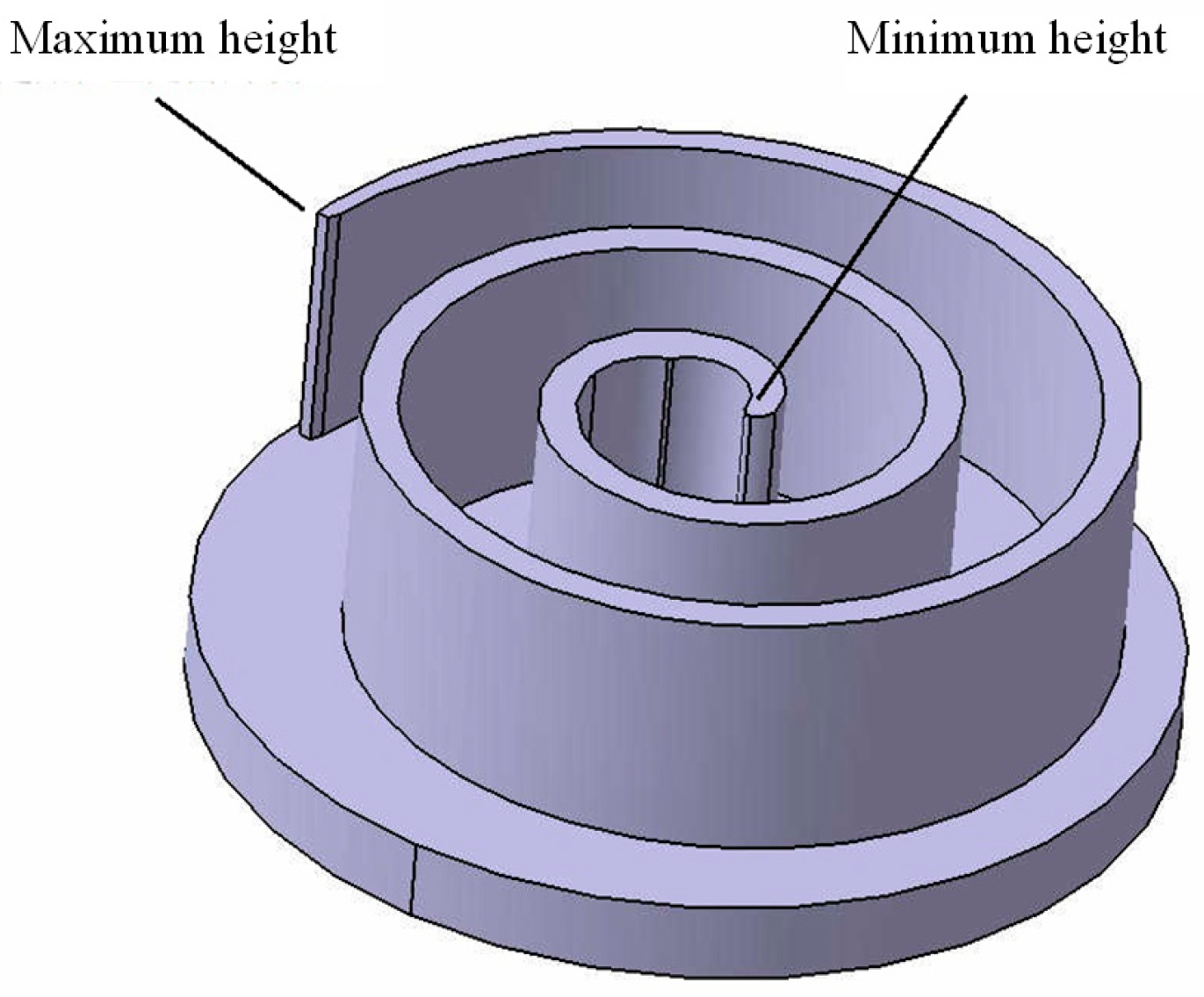
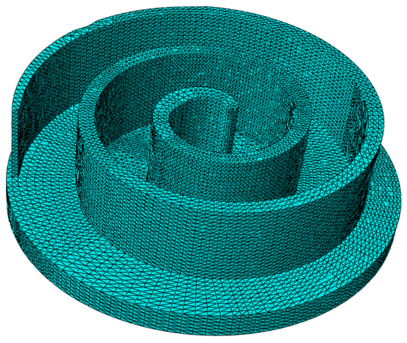
3.1. Geometric Modeling and Meshing

After taking into account the cyclical decrease in the height of scroll teeth along the axial direction induced by temperature variations, this paper proposes a design for a progressive tooth height scroll structure. In this design, the tip of the scroll tooth has a minimum height, with a gradual increase observed along the profile of the scroll tooth. This concept is illustrated and simplified in Figure 4.
The model parameters are specified as follows: tooth thickness is set to 3 mm, the radius of the base circle measures 1.65 mm, the maximum expansion angle of the profile is 5.5π radians, the initial tooth height is established at 19 mm, and the gradient of tooth height along the profile’s direction, denoting changes in height, is set at 10   μ m , 11   μ m , 12   μ m , 13   μ m , 14   μ m , a n d   15   μ m .
The rated power of this scroll compressor was selected as the research condition. At this time, the rotational speed is 6000 r/min, and the discharge pressure is 2.5 MPa.
The investigation focuses on the maximum deformation induced by the scroll teeth, pinpointing the start of discharge in the scroll compressor as the pivotal moment for force analysis of the moving scroll disc. Finite element analysis was employed, employing distinct mesh types to facilitate both heat transfer and hydrostatic analysis. Specifically, thermally coupled tetrahedral cell C3D4T was used for heat transfer considerations, while tetrahedral cell C3D4 was employed for hydrostatic evaluations. Subsequently, with a minimum cell size of 1 mm, the resulting finite element model consisted of 59,950 nodes and 293,317 cells, as shown in Figure 5. In this analysis, gray cast iron HT250 was used as the designated material for the dynamic vortex disc, with the relevant material parameters listed in Table 1.

3.2. Restrictive Condition

During compressor operation, the movable scroll disc is attached to the main shaft by axial positioning and secured to a bearing bore within the rotating shaft. A cross-slip ring, interlinked with the housing, serves to restrict the movement of the movable scroll disc, imposing specific limitations:
(1)
The rotational freedom of the movable scroll disc along the Z-axis is constrained to zero.
(2)
The dynamic bearing bore of the scroll disc is completely fixed in both the X and Y directions.

3.3. Acting Load

Throughout the operation of a scroll compressor, the various compression chambers experience complex forces, with their load dynamically shifting in correlation with the spindle rotation angle during the compression phase. The gas pressure in the Nth compression chamber can be determined using the equation governing adiabatic gas processes. The specific formula for this calculation is expressed as Equation (12):
p N = p 0 V s V θ K
where P 0 is the inlet pressure, P N is the pressure of the first N gas pressure of the first compression chamber, V s is the initial compression chamber volume, and   V N is the volume of the first N volume of the first compression chamber.
The radial force exerted by the gas within the scroll tooth is a consequence of the difference in pressure between its inner and outer sides. Given the geometrically symmetrical configuration of the scroll teeth, the application of gas pressure can be simplified as a differential pressure acting across multiple evenly spaced angular sectors, primarily impacting the inner wall surfaces. These forces correspond in magnitude to the difference in pressure between adjacent compression chambers. The specific calculation formula is Equation (13).
Δ p i = p N p N + 1
Throughout its operational phase, the gas pressure within individual compression chambers, together with the corresponding simplified gas forces exerted on inner wall surfaces, undergo continuous temporal fluctuations. Therefore, it becomes imperative to calculate the gas pressure exerted on the inner wall surface within each enclosed compression chamber separately, accounting for various operational scenarios. This study focuses specifically on the start of the exhaust phase, requiring calculation only at this point. At this precise moment, the spatial configuration between dynamic and static vortex discs is elucidated, as depicted in Figure 6.
As shown in Figure 6, in the case of scroll teeth where both the inner and outer walls are exposed to the same gas pressures, a state of equilibrium is achieved, resulting in the nullification of pressure differentials. Therefore, the focus lies on determining the angular extent of the scroll teeth where pressure differentials occur. Pressure differentials are quantified as follows: Δ p 1 = p 2 p 1 = 0.34   M P a , Δ p 2 = p p a i p 2 = 0.746   M P a .

4. Simulation Analysis

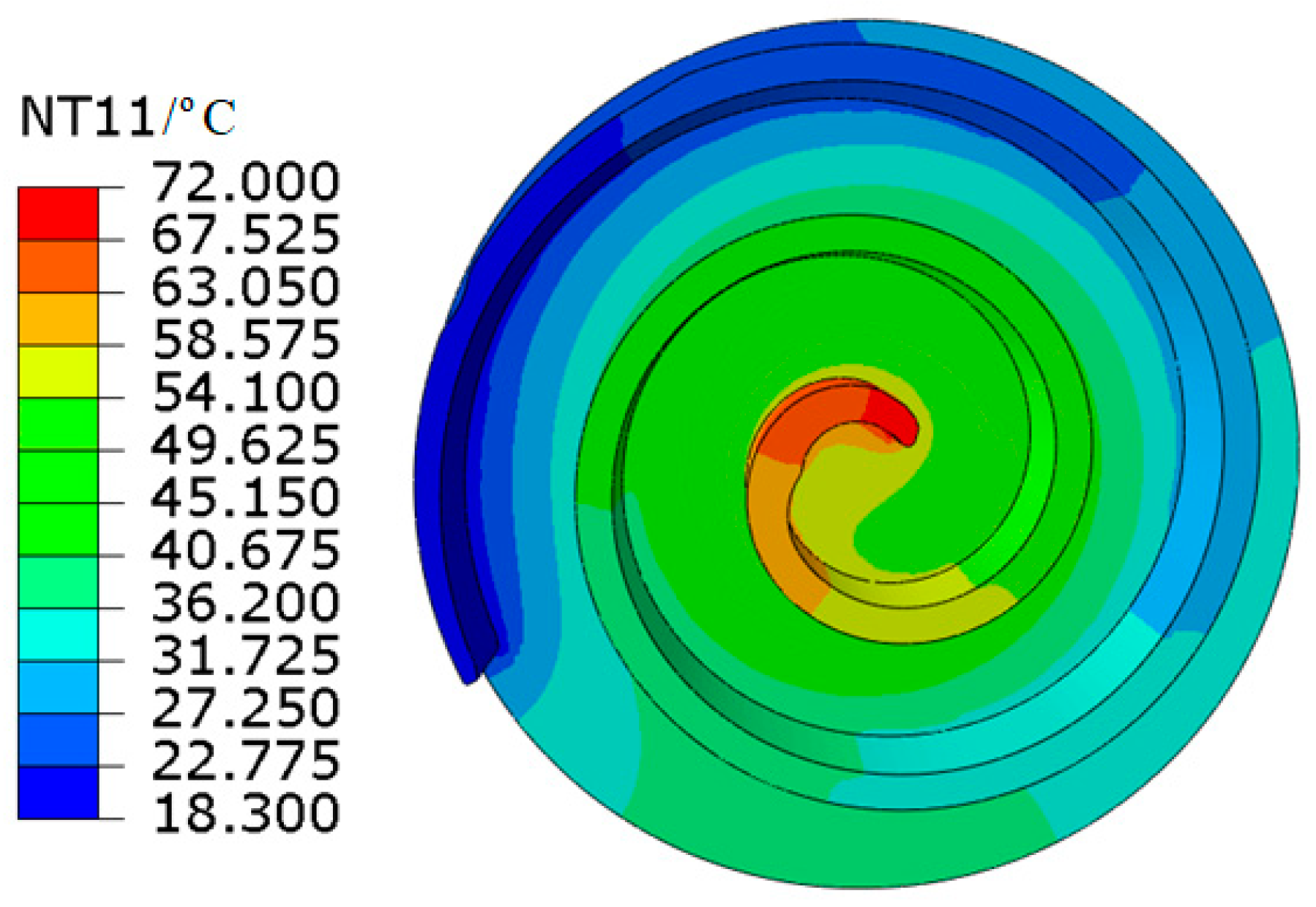
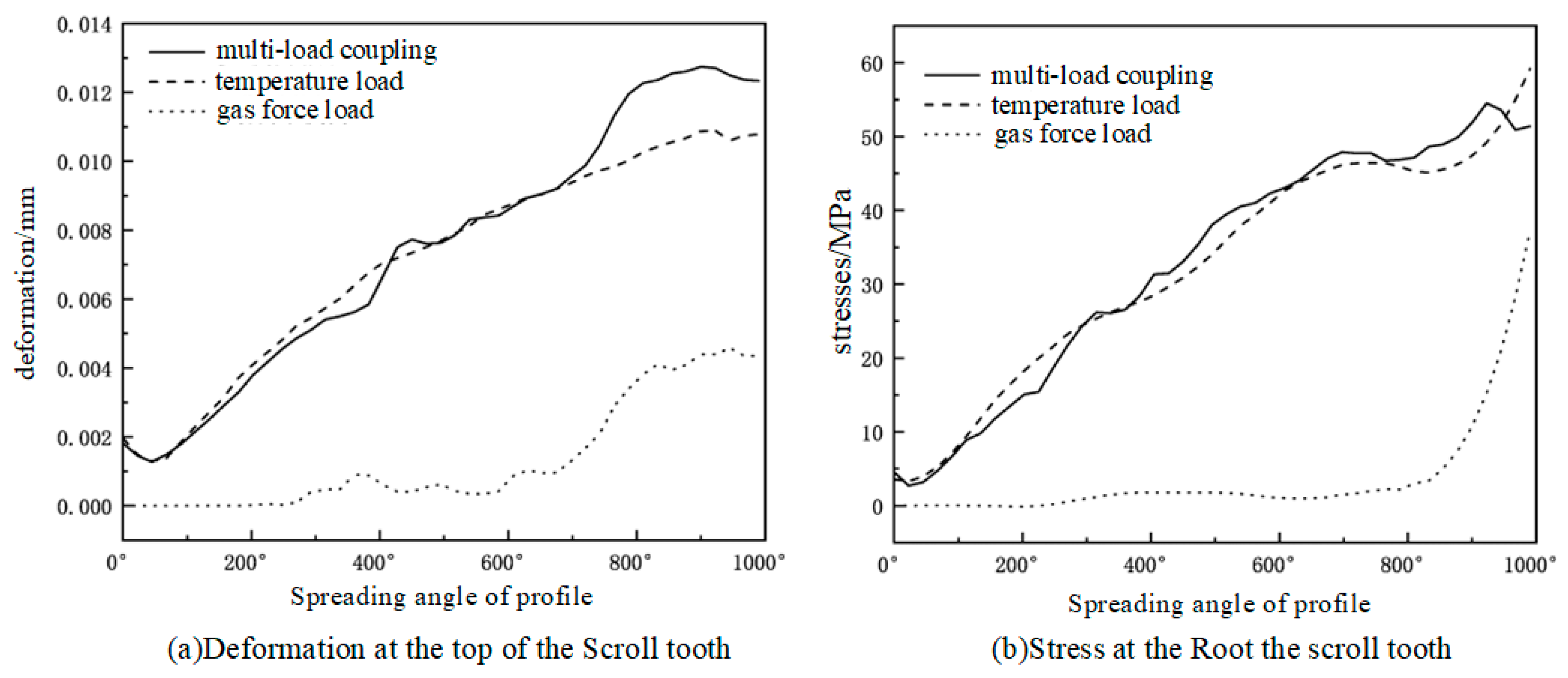
4.1. Temperature Load

As depicted in Figure 7, the suction temperature is recorded at 18 degrees Celsius, juxtaposed with the exhaust temperature peaking at 72 degrees Celsius. In addition, the temperature distribution across the scroll teeth of the scroll disc exhibits a gradual decrease as the profile unfolds. Notably, the temperature gradient on the bottom surface of the moving scroll disc exhibits a radial pattern characterized by a gradual decline from the central axis toward the periphery.
Figure 8 shows the effect of temperature load on the deformation of the scroll tooth. It is evident that the deformation diminishes gradually along the tooth profile, with the maximum deformation occurring at the apex of the tooth, measuring approximately 11 μm. Notably, the stress concentration is observed at the root of the scroll tooth, with the maximum stress registered at the root of the tooth head, measuring 58.37 MPa. This stress concentration can be attributed to the constraints imposed by the inner hole surface of the bearing mounting block and the near-right-angle connection between the scroll tooth and the end plate. The axial deformation of the scroll teeth is particularly affected by temperature loading, resulting in an expansion of the mounting gap, thereby reducing the volume of gas during the compression process.

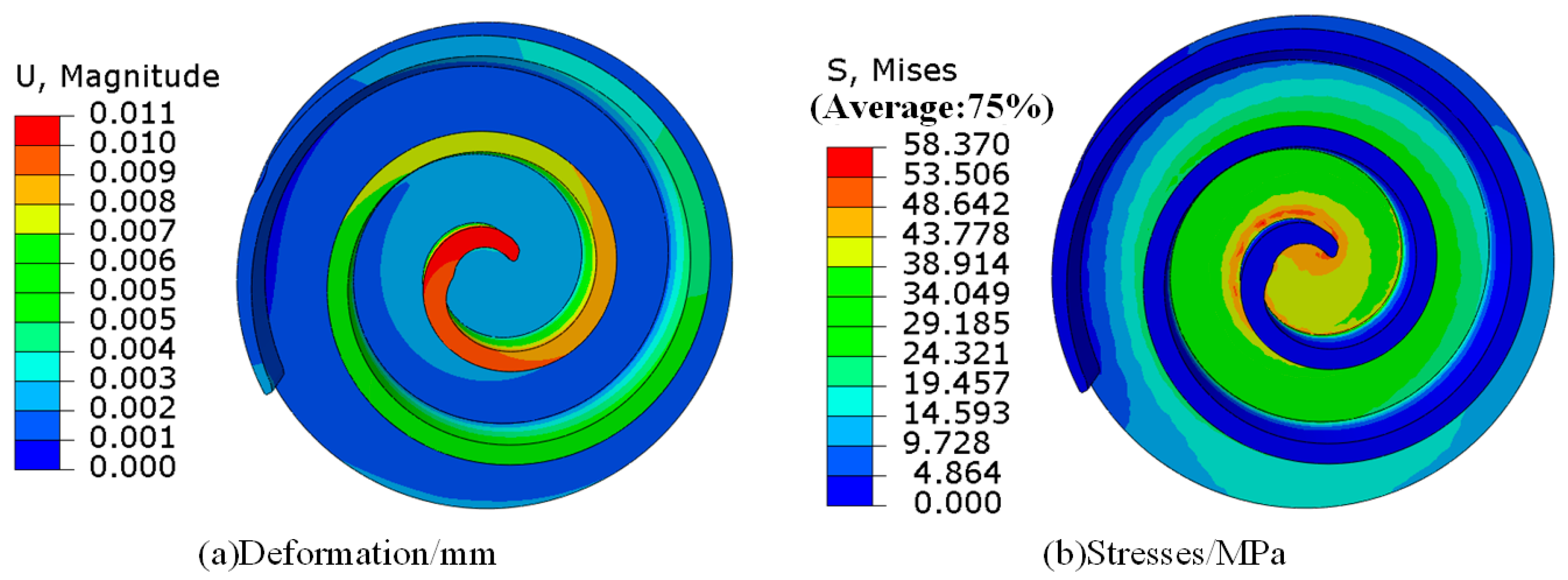
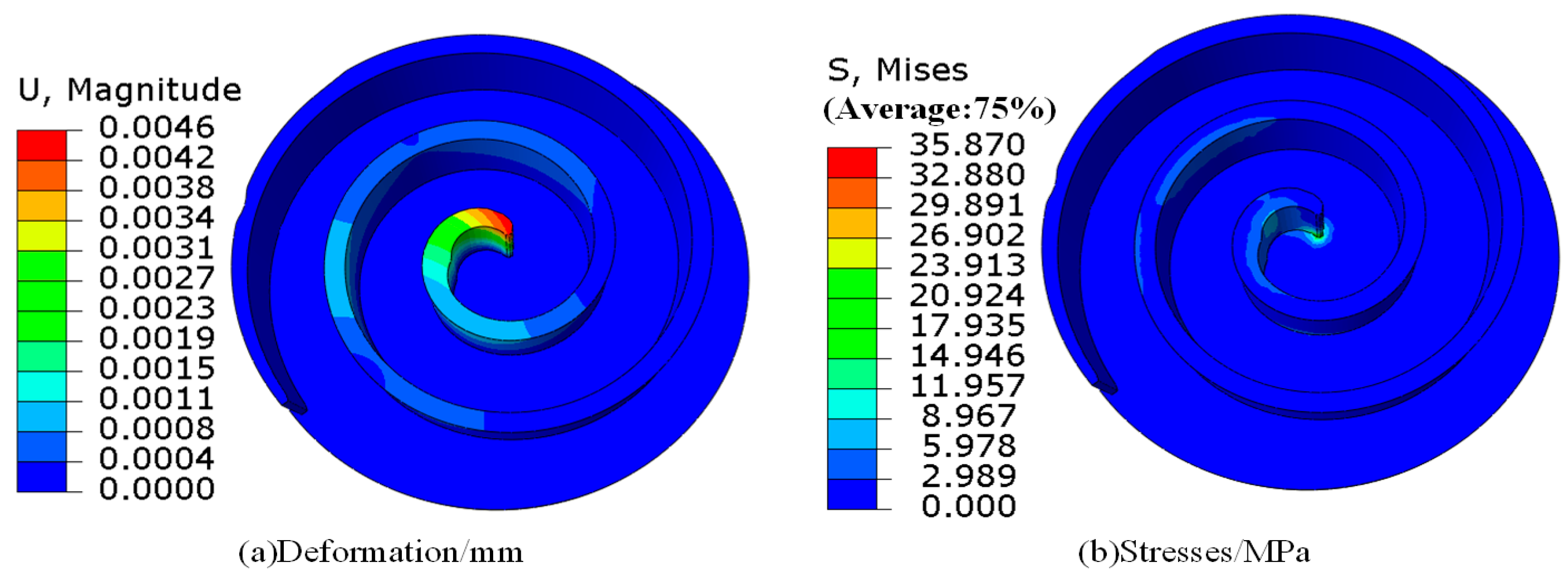
4.2. Gas Pressure Load
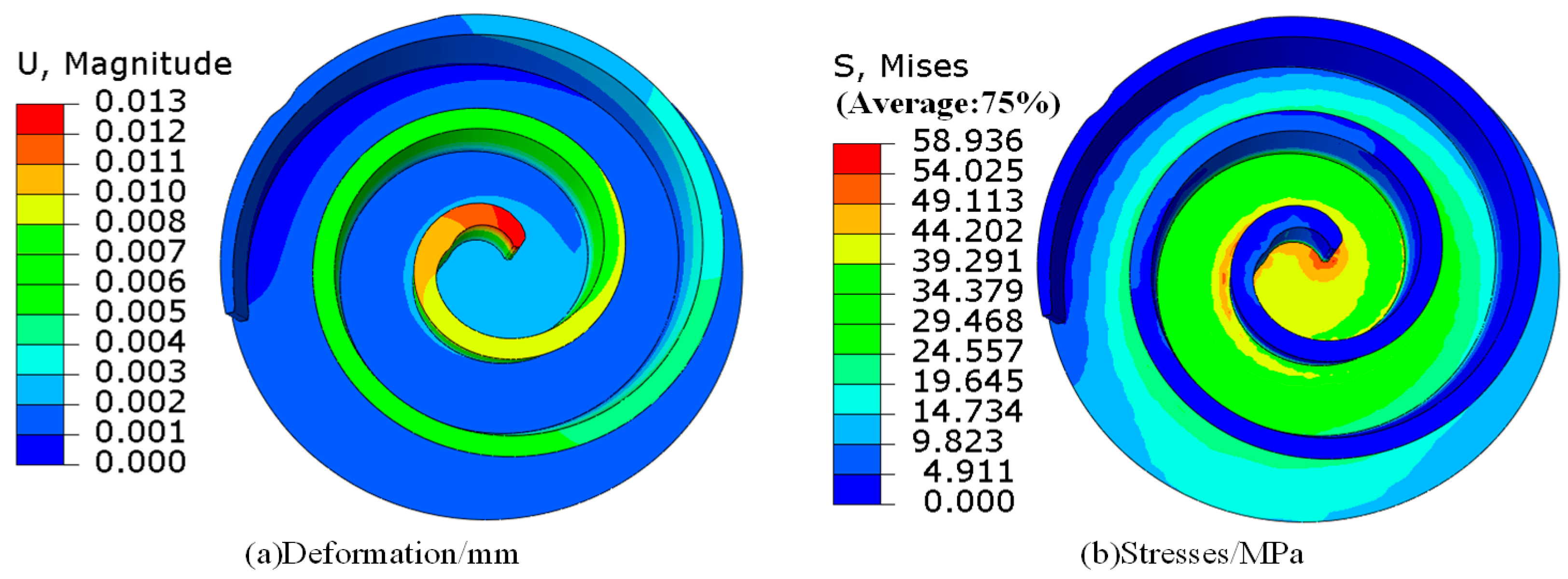
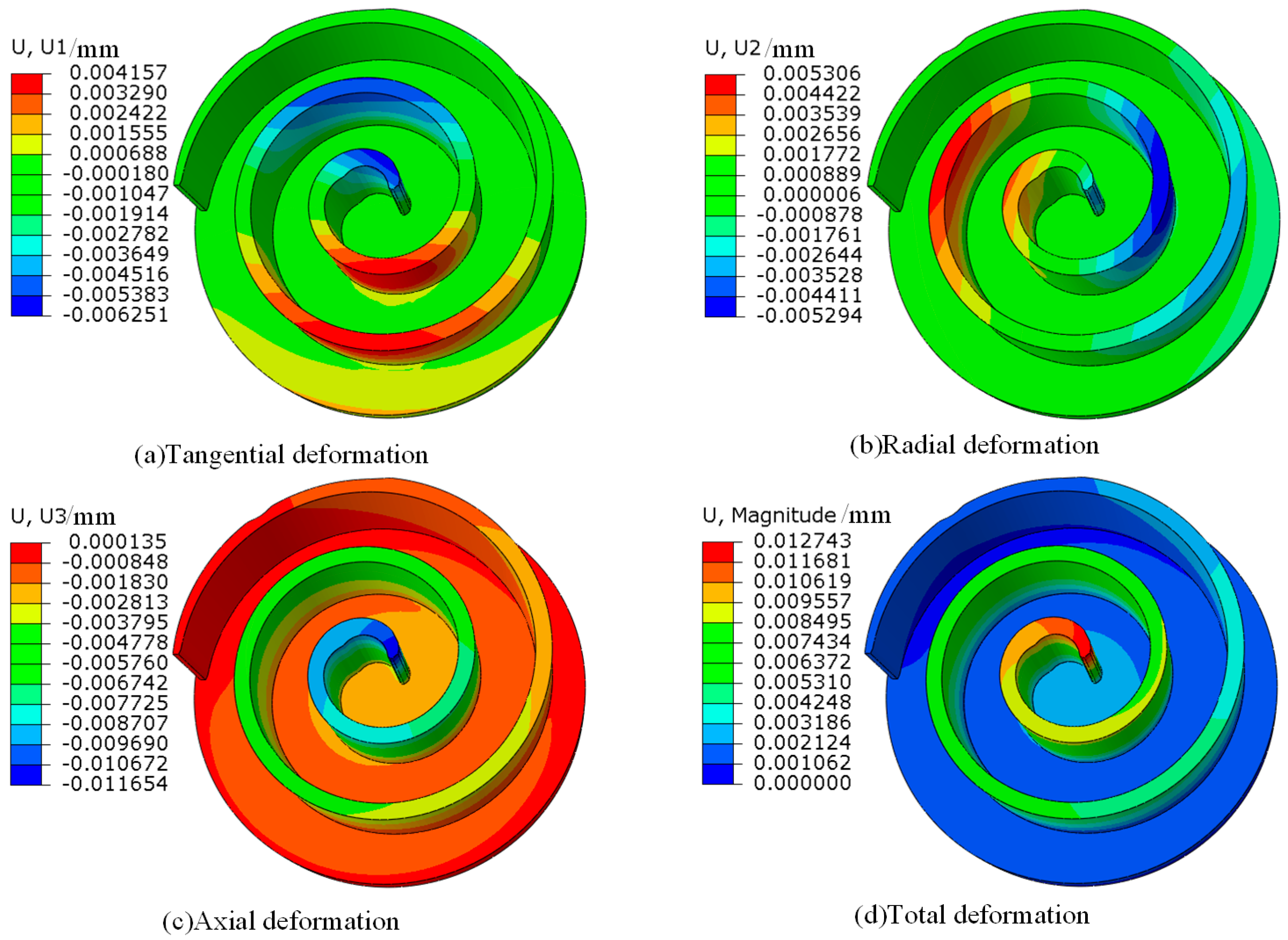
Figure 6 illustrates that, due to the inherent symmetry of scroll compressors, compression chambers typically occur in pairs, allowing for the presumption of equal volumes within each pair. Under conditions where the air pressure inside and outside the tooth surfaces remains the same, it is reasonable to posit that their pressures negate each other, thus rendering their loads negligible. Consequently, calculations focus solely on internal pressure loads within regions with pressure differentials.
Figure 9a illustrates that the central portion of the scroll tooth undergoes significant deformation, with the highest magnitude observed at the tooth head, measuring 4.5 μm. Deformation diminishes progressively toward the outer regions of the scroll tooth. This deformation pattern can be attributed to the vertical fixation of the scroll teeth on the end plate, similar to the loading configuration of a cantilever beam, resulting in such deformation distribution.
Analysis of the stress distribution depicted in Figure 9b reveals a predominant concentration in the vicinity of the exhaust chamber. The highest stress level, at 35 MPa, occurs at the root of the tooth head, while stress elsewhere is relatively minimal. This stress concentration phenomenon arises from the substantial difference in pressure between the inner and outer sides of the vortex tooth near the exhaust chamber. In addition, vertical fixation between the tooth root and the end plate, coupled with abrupt changes in cross-sectional area, contributes to stress concentration at the tooth root.

4.3. Multi-Load

Figure 10 illustrates that the apex of the vortex tooth experiences the highest deformation, measuring 13 μm, under multiple loads. At present, the maximum stress concentration is observed at the base of the vortex tooth, peaking at 58 MPa. This deformation and stress distribution pattern closely resembles that observed when subjected solely to thermal loading. This congruence can be attributed mainly to the relatively lower rotational speed of the scroll disc and the reduced exhaust pressure, where thermal stress emerges as the dominant factor governing the deformation and stress distribution of the scroll teeth.
The deformation of the scroll disc mainly occurs in the upper part of the scroll tooth, while the stress mainly accumulates at the root of the scroll tooth. Subsequent analysis of the deformation and stress distribution of the scroll tooth focuses primarily on these two distinct regions: the root and the apex of the tooth. This analysis is further elaborated in Figure 11.
Figure 11 shows that the deformation and stress distribution of the scroll teeth show similarities under both multiple loads and temperature alone. Particularly noteworthy is that within the profile spread angle range of 900° to 990°, the maximum deformation experienced under multi-loading conditions amounts to 12.7 μm, whereas under the sole influence of temperature load, it reaches 10.6 μm. This discrepancy is considerable. Additionally, the maximum deformation induced solely by gas force stands at 4.5 μm. Notably, the effect of gas force on scroll tooth deformation is pronounced primarily in instances where the pressure disparity between the internal and external environments of the scroll tooth is substantial near the exhaust orifice. Conversely, at other locations, the effect of the gas force on the stress and strain of the scroll tooth appears to be relatively minimal.

4.4. Deformation Law of Asymptotic Tooth Height under Multiple Loads

Based on the above analysis results, it becomes apparent that the deformation of the scroll tooth occurs mainly within the scroll tooth head. Therefore, the analysis of deformation in high scroll teeth with asymptotic profiles focuses mainly on the scroll tooth head, especially in close proximity to the central compression chamber. The deformation and total deformation of the scroll disc in all directions are shown in Figure 12. The specific pattern of deformation distribution is shown in Figure 13, with corresponding comparative data presented in Table 2.
Figure 13 shows that the dominant deformation exhibited by the scroll tooth mainly manifests as radial deformation, indicating deformation along the height direction of the tooth. Conversely, deformation along the tangential and axial directions, denoted tangential and axial deformation, respectively, exerts minimal influence on the overall deformation of the scroll tooth. Furthermore, it is observed that incremental changes in tooth height yield negligible impact on the maximum deformation of the scroll tooth, with deformation values ranging between 12 to 13 μm. Notably, the least deformation rate is observed at the asymptotic height of 13 μm, coinciding with a maximum deformation of 12.5 μm and a deformation rate of 0.26.

4.5. Result Reliability Analysis

In order to verify the accuracy of the finite element model of the moving vortex disk, this study carried out a comprehensive analysis and comparison with the relevant literature. Li et al. [20] pointed out that no matter what kind of working conditions, the stress mainly occurs at the root of the tooth head, and deformation is mainly concentrated on the top of the tooth head. Xie [21] shows that under the action of multi-field coupling, the head of the scroll tooth has the greatest deformation, and thermal deformation is the main factor affecting the deformation of the scroll tooth. Wei [22] studied scroll discs with different lines and found that the stress is mainly concentrated on the connection between the scroll tooth and the end plate, and the deformation occurs mainly at the head of the scroll tooth. The simulation results obtained in this study are consistent with the conclusions of the above literature, ensuring the reliability and accuracy of the analysis methods and conclusions in this paper.

5. Conclusions

(1) The reliability of the analysis results was enhanced by optimizing the steady-state temperature distribution model for the scroll disc, providing a more accurate prediction of the temperature distribution across the scroll disc under various operating parameters. This refined methodology allows a more accurate assessment of the mechanical properties of the scroll disc, including force and deformation characteristics.
(2) At low rotational velocities, the maximum deformation and stress distribution of the scroll tooth are intricately related to thermal loading conditions. These specific conditions result in a maximum deformation of 13 μm at the tooth head and a maximum stress of 58 MPa. In particular, the magnitude of deformation at the tooth head significantly exceeds that of the tooth tail. The stress concentration occurs mainly at the root of the scroll tooth.
(3) The deformation of asymptotic scroll teeth occurs mainly along the tooth height axis, with little influence on the rate of change in scroll teeth height remaining within this specified range for optimal function.

Author Contributions

Writing—original draft preparation, B.Y. and A.L.; writing—review and editing, M.Y., J.W., F.G. and M.G. All authors have read and agreed to the published version of the manuscript.

Funding

This study was supported by the National Natural Science Foundation of China (grant no. 12372079), the Natural Science Foundation of Jiangsu Province, China (grant no. BK20201470), and the Fund of Nanjing Institute of Technology (grant no. CKJB202205).

Institutional Review Board Statement

Not applicable.

Informed Consent Statement

Not applicable.

Data Availability Statement

The data presented in this study are available on request from the corresponding author. The data are not publicly available due to privacy.

Acknowledgments

We appreciate the editors and referees for their beneficial remarks and advice, which have greatly contributed to the clarity of the paper. The authors are grateful to Xuan Ma, Jiajia Zou, and Xingyu Zhang from the Nanjing Institute of Technology for their valuable discussions.

Conflicts of Interest

The authors declare no conflicts of interest.

References

  1. Liu, H.; Liu, J.; Zhao, H.J.; Jiang, Y.; Huang, X.Y. Aerodynamic noise analysis of suction and discharge valves of linear compressor based on multi physical field coupling. Chin. Hydraul. Pneum. 2023, 47, 68–76. [Google Scholar]
  2. Zhang, Y.B.; Peng, B.; Zhang, P.C.; Sun, J.; Liao, Z.X. Key technologies and application of electric scroll compressors: A review. Energies 2024, 17, 1790. [Google Scholar] [CrossRef]
  3. Peng, Q.H.; Du, Q.G. Progress in heat pump air conditioning systems for electric vehicles—A review. Energies 2016, 9, 240. [Google Scholar] [CrossRef]
  4. Cheng, J.M.; Yang, Z.J. Summarization of flow field analysis of scroll compressor compression chamber. Petro-Chem. Equip. 2016, 19, 49–50. [Google Scholar]
  5. Tian, S.G.; Wang, C.; Zhao, Y.Y. Research progress and development trend of scroll compressor. Refrig. Air-Cond. 2021, 21, 72–77+86. [Google Scholar]
  6. Liu, G.P.; Li, J.F.; Gong, Q. Finite element analysis based on moving thermal boundary for orbiting scroll wrap’s temperature distribution. Chin. Hydraul. Pneum. 2019, 1, 65–70. [Google Scholar]
  7. Wang, J.T.; Liu, G.P.; Hu, R.H.; Yu, T.F. Temperature-fields simulation of scroll gears of wind-cooling oil-free scroll air Compressor. Chin. J. Vac. Sci. Technol. 2015, 35, 1225–1230. [Google Scholar]
  8. Wang, J.T.; Liu, G.P.; Yu, T.F.; Xiao, G.F.; Song, H.G. Research of scroll air compressor with asynchronous discharge of symmetric chambers. China Mech. Eng. 2014, 25, 2715–2718. [Google Scholar]
  9. Li, Y.Z. Flow Field Characteristics of the Scroll Compressor and Stress-Strain Analysis of Orbiting Scroll Wrap. Master’s Thesis, Lanzhou University of Technology, Lanzhou, China, 2023. [Google Scholar]
  10. Hirano, T.; Hagimoto, K.; Maeda, M. Study on scroll profile for scroll fluid machines. Trans. Jpn. Soc. Refrig. Air Cond. Eng. 2011, 8, 53–64. [Google Scholar]
  11. Meng, H.; Li, A.; Li, H.S.; Feng, W.G.; Chen, J.H.; Cui, Z. Research on deformation behavior of grooved scroll teeth for oil-free scroll compressor. Fluid Mach. 2022, 50, 66–72+104. [Google Scholar]
  12. Li, X.R.; Wu, W.F.; Zhang, J.; Guo, C.Q.; Ke, F.; Jiang, F.Q. Analysis of 3D transient flow in a high-speed scroll refrigeration compressor. Energies 2023, 16, 3089. [Google Scholar] [CrossRef]
  13. Ballani, A.; Pasunurthi, S.S.; Srinivasan, C.; Maiti, D. Performance Prediction of an e-Compressor Using 3D CFD Simulation; SAE Technical Paper; SAE International: Warrendale, PA, USA, 2023. [Google Scholar]
  14. Cavazzini, G.; Giacomel, F.; Benato, A.; Nascimben, F.; Ardizzon, G. Analysis of the inner fluid-dynamics of scroll compressors and comparison between CFD numerical and modelling approaches. Energies 2021, 14, 1158. [Google Scholar] [CrossRef]
  15. Wang, J.; Liu, Q.; Jiang, Y.; Wang, Z.L.; Cha, H.B. Temperature distribution and deformation of scroll wraps for scroll compressors. J. Eng. Thermophys. 2016, 37, 2344–2348. [Google Scholar]
  16. Wu, Z.; Feng, Z.G.; Su, Y.F. Simulation and analysis of internal flow field in scroll compressor with circular involute profile. Mech. Sci. Technol. Aerosp. Eng. 2019, 38, 1840–1846. [Google Scholar]
  17. Li, X.Q.; Wang, Z.L.; Wang, J. A simplified method of calculating working chamber volumes for scroll machinery. Compress. Technol. 2009, 5, 25–28. [Google Scholar]
  18. Li, J.F. Structure Optimization Design of Scroll Compressor for Scroll Based on Thermodynamics. Master’s Thesis, Nanchang University, Nanchang, China, 2019. [Google Scholar]
  19. Yang, M.H. Research on the Methods to Decrease Discharge Temperature of R32 Scroll Compressor. Master’s Thesis, Tsinghua University, Beijing, China, 2015. [Google Scholar]
  20. Li, C.; Xie, W.J.; Zhao, M. Deformation and stress analysis of orbiting scroll under the multi-field coupling. Fluid Mach. 2013, 41, 16–20. [Google Scholar]
  21. Xie, W.J. The Finite Element Analysis on Orbiting and Fixed Scrolls of Oil-Free Scroll Compressor. Master’s Thesis, Lanzhou University of Technology, Lanzhou, China, 2013. [Google Scholar]
  22. Wei, N. Scroll Compressor Based on Combined Profile Change Study on Performance of working CHAMBER. Master’s Thesis, Lanzhou University of Technology, Lanzhou, China, 2023. [Google Scholar]
Figure 1. Schematic diagram of scroll tooth heat transfer.
Applsci 14 05977 g001
Figure 2. Schematic diagram of line spreading angle.
Applsci 14 05977 g002
Figure 3. Steady-state temperature distribution on the wall surface of the vortex tooth.
Applsci 14 05977 g003
Figure 4. Geometric model of a moving vortex disc.
Applsci 14 05977 g004
Figure 5. Finite element model of moving vortex disc.
Applsci 14 05977 g005
Figure 6. Relationship between dynamic and static vortex disc positions at the start of exhaust gas discharge.
Applsci 14 05977 g006
Figure 7. Temperature distribution characteristics.
Applsci 14 05977 g007
Figure 8. Deformation and stress distribution of moving vortex disc under temperature loading.
Applsci 14 05977 g008
Figure 9. Deformation and stress distribution of moving vortex disc under gas force loading.
Applsci 14 05977 g009
Figure 10. Deformation and stress distribution of moving vortex disc under multi-load coupling.
Applsci 14 05977 g010
Figure 11. Deformation and stress distribution pattern of vortex teeth of moving vortex discs.
Applsci 14 05977 g011
Figure 12. Schematic of deformation.
Applsci 14 05977 g012
Figure 13. Maximum deformation pattern of high vortex disc with graduated.
Applsci 14 05977 g013
Table 1. Basic material parameters.
Name of MaterialNumerical Value
Modulus of elasticity (MPa)1.38 × 10⁵
Poisson’s ratio0.156
Density (t/mm3)7.28 × 10−9
Coefficient of thermal expansion (m/(m·K))8.2 × 10−6
Heat transfer coefficient (W/(mm·K))0.045
Specific heat capacity (mJ/(t·K))510
Table 2. Deformations of high vortex teeth with gradual tooth heights.
Gradient   Height   ( μ m ) Maximum   Deformation   ( μ m ) Deformation Rate
1013.11.58
1112.8 0.93
1212.9 0.48
1312.5 0.26
1412.5 0.79
1512.9 1.10
Disclaimer/Publisher’s Note: The statements, opinions and data contained in all publications are solely those of the individual author(s) and contributor(s) and not of MDPI and/or the editor(s). MDPI and/or the editor(s) disclaim responsibility for any injury to people or property resulting from any ideas, methods, instructions or products referred to in the content.

