Abstract
A global analysis of a rack frame conducted using the Generalised Beam Theory (GBT) is presented. This study specifically focuses on a down-aisle frame, showing the particular characteristics of this type of structure, such as its perforated columns, semi-rigid joints, and significant second-order effects. The single-column simplified approach is applied, meaning that the entire rack is modelled with one single column and its adjacent half-beams. This approach substantially reduces modelling time and allows for very quick parametric studies while adequately reproducing the general 2D down-aisle behaviour. The GBT single-column model is first verified against a similar single-column shell finite element model used by the authors in previous research. Afterwards, the model is applied to study the effects of various factors influencing the results of a rack global analysis, including perforations, imperfection magnitudes and combinations, and sectional deformations. The nature of GBT allows for deriving clear conclusions on the influence of these aspects on structural behaviour. Furthermore, this article also aims to demonstrate the potential advantages of the theory for performing global analyses of these structures in both research and design.
1. Introduction
A global analysis of a cold-formed steel rack structure presents considerable challenges, given the many factors that necessitate consideration, particularly in contrast to the analysis of conventional steel structures. Analyses and design approaches in the scientific literature and standards [1,2,3] typically rely on finite element models, ranging from simple 2D beam models to sophisticated 3D shell models. While simple beam models offer advantages such as easy modelling, quick computation, and straightforward result interpretation, their performance is limited since sectional deformations and perforations cannot be directly accounted for. To overcome these limitations, equivalent and/or effective cross-section properties or specific stiffness reduction factors must be employed [1,3]. In contrast, shell finite element models can simulate rack structure behaviour realistically but at a much higher modelling and computational cost. Furthermore, when shell models are to be applied in the design of such structures and even in research, significant simplifications have to be introduced to maintain efficiency [4]. For instance, simplified modelling of joints is almost obligatory since contacts and looseness are very difficult to include in a global analysis at a reasonable cost. Therefore, it can be concluded that the use of realistic shell models is not the ideal solution either. Alternatively, this study tackles the global analysis of rack structures using the Generalised Beam Theory (GBT). The current state of the art of this theory is not at the level of shell finite element approaches, especially for comprehensive modelling of joints, including aspects such as the mentioned contacts. Nevertheless, one of its advantages lies in the dual nature of GBT beam finite elements, encompassing both beam and shell characteristics within the same element. This allows the theory to take advantage of some of the benefits of each element type. Additional positive aspects of the theory will be shown in the paper. This is one of the first in-depth studies devoted to the global analysis of adjustable rack structures using GBT, and it aims to demonstrate the potential future contributions of the theory in this field.
Adjustable pallet rack systems are steel structures designed to store products. Figure 1a shows that pallet rack systems are composed of uprights, beams and braces (diagonals). Commonly, all these structural members are made of thin-gauge cold-formed steel profiles. The following two horizontal directions are distinguished: (i) the transverse one, referred to as the cross-aisle; (ii) the longitudinal one, termed the down-aisle. The cross-aisle direction is braced; the corresponding braced structures are termed upright frames (Figure 1a). Racks can also be braced in the down-aisle direction, but in this study, only unbraced frame racks are considered (Figure 1a). Finally, speed-lock beam-to-upright connections are employed to facilitate rack erection based on inserting hooks into upright perforations (tabs), as described in Figure 1b.
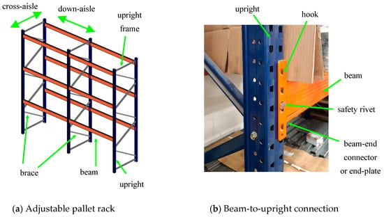
Figure 1.
Typical adjustable pallet racking systems.
The global, member, and joint behaviours of racks are influenced by numerous factors, making them very particular. Those considered most relevant are included in the following list [1,2,3]: (i) columns are made of open thin-walled profiles, thus they generally undergo significant sectional deformations, ultimately leading to local and distortional buckling; (ii) columns are weak and flexible against warping torsion, and their cross-sections are monosymmetric, meaning that the effects of centroid and shear centre eccentricity are relevant; (iii) columns show multiple small perforations, which have a non-negligible impact on the stiffness and strength of the structure [4,5]; (iv) the slender nature of the profiles and the global structure increases the geometrically nonlinear effects and, consequently, the influence of initial imperfections; (v) beam-to-column and floor joints are semi-rigid, exhibiting nonlinear behaviour and important load transfer through contact between components (bolts and welding are relatively uncommon); (vi) this latter aspect also intensifies the impact of the looseness in both down- and cross-aisle joints; and (vii) the eccentricities at the joints may have an important effect. Most of these factors are routinely considered in design, specifically when performing global analyses of rack structures.
Concerning recent research on global analysis, it is worth mentioning the work by Benurzzi et al., who showed the key role of the warping degree of freedom in pallet racks [6,7,8,9]. By comparing analyses conducted using 3D beam elements with 6 and 7 degrees of freedom (where the 7th degree is warping), they proved that warping needs to be considered in linear buckling analyses to correctly determine the elastic buckling factor of the structure (see also [10]). Furthermore, in second-order geometrically nonlinear analysis, the seventh degree of freedom allows for the determination of the warping moment (bi-moment) and also accounts for the interaction between torsion and bending, which increases horizontal displacements and bending moments. These effects of warping seem to be especially important at the lateral columns of the rack structure (end columns presenting beams at only one side) [6]. Nowadays, most studies using beam elements already incorporate the 7th degree of freedom in the analysis, as seen in [11,12,13].
Another topic of recent research on the analysis of racks is the effect of local and distortional deformations and that of their corresponding imperfections on the overall behaviour of the structure. Trouncer and Rasmussen compared in [14] the strength predictions of racks derived from beam and shell finite element models. Beam model predictions were actually determined from geometrically nonlinear analysis (GNA) internal forces and checking capacities according to current standards, while the “advanced” design approach was applied to directly determine the ultimate strength of the racks from the shell model and geometrically and materially nonlinear analysis with imperfections (GMNIA). They proved that as the slenderness of the column sections increases and, consequently, the sectional deformations become relevant, the predictions from the beam element models worsen with respect to those of the shell elements, overestimating the strength. The reason for the unsafe calculated design loads is attributed to the fact that the GNA analysis-based design does not take into account the additional second-order deformations produced by local and/or distortional buckling of the columns. In another study from the same research team [15], it was demonstrated that, despite the relevant effects of the sectional deformations on the final results of the global analyses, the influence of the corresponding sectional imperfections is not important, especially for unbraced down-aisle rack frames. Notably, part of this study is devoted to discussing the effect of distortional imperfections (see also [16]).
Apart from all the above-mentioned main aspects that influence global analysis of racks, there are others that have attracted the attention of researchers and standardisation committees, such as the residual stresses and partial yielding of the cross-sections [3,16], particular loading patterns and accidental actions [1,2,17], ground–structure interactions [1], and stiffening effects of the pallets [17].
Current design standards for racks offer various approaches to conducting comprehensive global analyses, aiming to account for all considerations presented so far. On the one hand, the most advanced proposals in Europe and America [2,3] are based on member checks using internal forces determined in beam finite element geometrically nonlinear analysis with imperfections (GNIA). Both in Europe and America, semi-rigid joints have to be included in the model, as well as global sway imperfections (or equivalent horizontal forces) and, depending on the final member checking applied, member imperfections. Analysing down-aisle frames can be carried out separately from the cross-aisle upright systems if the relevant interactions are considered. In Europe, looseness affecting the down-aisle direction can be taken into account through supplementary sway imperfection, and the reduction in stiffness produced by the column perforations is considered through an equivalent cross-section. In America, reduced cross-section area properties are also proposed to cover the effect of perforations [2], and additional stiffness reduction factors are used for all members that contribute to the stability of the structure. The readers are referred to the corresponding standards for detailed information [1,2,3]. Noticeably, none of these documents offers clear instructions on torsion when conducting the global analysis, as Bernuzzi et al. already pointed out in their studies [7]. Contrarily, the study by Rasmussen et al. in [18], which introduces the Australian design standard for rack design, shows explicit instructions on how to deal with the effects of warping torsion. Furthermore, this standard opens the door to advanced analysis based on shell finite element models to directly determine the ultimate strength of the rack by means of GMNIA. In this manner, perforations, sectional deformations and instabilities, warping torsion effects and eccentricities can be taken into account more realistically. Concerning beam and shell finite element models, it can be considered that the Australian standard is the most innovative and the closest to the current scientific state-of-the-art in relation to the global analysis of racks.
In this study, the authors propose an analysis approach based on the GBT. Thanks to the dual nature of the GBT finite elements, torsion and sectional deformations are naturally accounted for, along with perforations [19], without facing the modelling costs associated with shell FEM, particularly concerning joints. Most of the existing global analyses with GBT have been mainly focused on simple portal frames composed of channels or I-sections. The main problem in GBT is to model the joints [20]. This is probably why researchers moved from initial pure GBT frame models [21,22,23] to models that combine GBT beam elements for members and shell elements for joints [24,25]. However, the GBT modelling of joints in racks can be simpler because its nature does not allow for a direct and complete transmission of the torsional warping degree of freedom or local and distortional deformations. This connection is commonly made by means of hooks and tabs, and consequently, the beam warping deformations are just partially transmitted to the column through localised contacts. It seems reasonable to model these connections in a simplified manner when carrying out a global analysis of a pallet rack structure (Only global GBT deformation modes and eccentricities are considered). As a result, the experimentally measured beam-to-column and floor connection stiffness can be directly incorporated into the model, similar to a beam FE model. These ideas prompted the initiation of this study.
An outline of the paper follows. Section 2 presents the formulation applied to model perforated and non-perforated rack members in GBT. Section 3, Section 4, and Section 5 describe the rack structure utilised throughout the study, together with the corresponding shell and GBT finite element models. The GBT model is validated against shell finite element results in Section 6. The effect of sectional deformations and member and sectional imperfections on the results of the global analysis is investigated in Section 7. The particular modal approach of GBT is utilised; deformation modes and imperfections can be activated at one’s discretion, allowing for a clear study of the effect of each one. This article also shows how some of the various aspects to be considered in the analysis of rack structures discussed in this introduction are implemented in a GBT model. In Section 8, the advantages of GBT observed in this modelling process are highlighted. The concluding remarks of Section 9 close the paper.
2. GBT Formulation
Two main steps are required to carry out a GBT calculation: (i) cross-sectional and (ii) the member analyses. The GBT cross-sectional deformation modes, as well as the modal matrices, are determined in the first step. On the other hand, member equilibrium is solved during the second step.
The member displacement field is described, according to each sectional wall local coordinate system (Figure 2), through the use of Equations (1) and (2), in which uk(s), vk(s), wk(s), and ϕk(s) are the cross-sectional shape functions and the modal amplitude function, and k corresponds to each deformation mode. The deformation modes can be classified into different groups according to their main kinematic characteristics: (i) conventional modes (warping and in-plane displacements are considered and Vlasov’s hypothesis are assumed), (ii) natural shear modes (only involve in-plane displacements and shear membrane strain is allowed), (iii) transverse extension modes (only involve in-plane displacements and the extension of sectional walls is allowed), and (iv) local shear modes (only involve warping displacements).
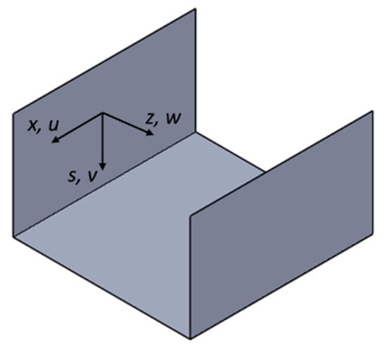
Figure 2.
Sectional wall local coordinate system used to describe the displacement field.
A full set of Green–Lagrange membrane strains, small-strain bending effects, and a total Lagrangian kinematic description were used. Thus, the strains were calculated through the use of Equations (3)–(5).
The member strain energy was determined by means of Equation (6), where and are the strain energy terms of the total gross member domain (V) and the perforation domain (Vp), respectively. Conversely, and correspond to the strain energy terms of the initial geometrical imperfection. Notice that and only have to be computed to take the influence of perforations into account.
An isotropic elastic material behaviour and a 2-node GBT beam finite element were applied to solve the member equilibrium equation. The degrees of freedom of the GBT beam element are the values of the amplitude function and/or the amplitude function derivative. Hermite cubic polynomials were used to describe conventional, natural shear, and transverse extension modes. On the other hand, Lagrange cubic polynomials were used for the axial extension and local shear modes (deformation modes that only involve warping displacements).
The finite element internal force vector () and tangent stiffness matrix () were calculated by differentiating the strain energy and the internal force vector, respectively (Equations (7) and (8)). Finally, an incremental–iterative process based on the Newton–Raphson algorithm was adopted to solve the geometrically nonlinear analysis. The full procedure and finite element implementation are completely described in [19].
3. Rack Structure Used in the Study
The down-aisle stiffness and strength of unbraced racks mainly depend on the behaviour of their uprights, beams, and beam-to-upright and floor joints. These components are described below for the rack under study.
With regard to the structural members, their overall dimensions are specified in Figure 3. The upright consists of a regularly perforated open section (Figure 3a), while the beam is a rectangular tube composed of two mutually nested C-lipped sections (Figure 3b).
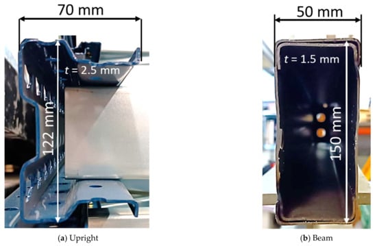
Figure 3.
Profiles.
Concerning joints, those of the floor consist of a folded plate, bolted to the front of the upright and anchored to the ground (Figure 4a), while the beam-to-upright one uses a L-shaped plate, welded to the beam end, and hooked to the upright (Figure 4b). The upright holes and plate hooks shown in Figure 4 are blurred due to confidentiality issues. The rotational behaviour of beam-to-upright and floor joints is obtained by testing according to [1].
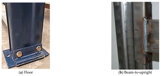
Figure 4.
Connections [26].
The pallet rack has a significant number of bays (e.g., 30 bays, see Section 4) and five loading levels (excluding the floor level). The bay width is 1.8 m, measured between centroids of consecutive uprights, and the level heights are 1.5 m. The weight of the stored goods at each slot is 3.4 Tones, leading to a load of 17 kN per beam. Figure 5 displays a sketch of such a rack.
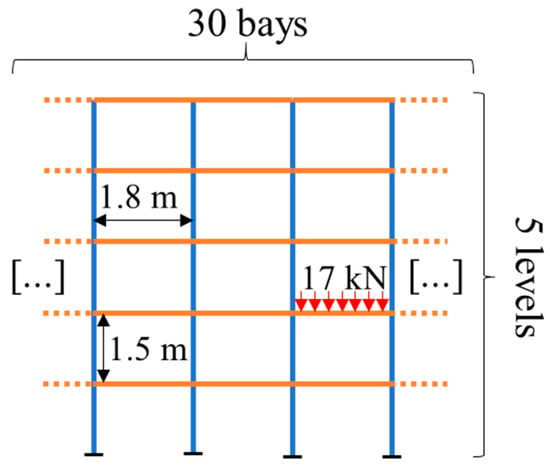
Figure 5.
Sketch of the rack.
4. Shell Finite Element Model of the Structure
The structure was analysed with Ansys Mechanical APDL [27]. A single-column modelling approach, similar to that proposed by Godley et al. [28], was applied (see also [29]). The model consists of one single upright made with Mindlin–Reissner shell elements, with half-span beams connected at both sides, modelled with 6-DOF/ node Euler–Bernoulli beam elements. Two models for the upright were analysed, with and without perforations; in both cases, the cross-section corners were considered sharp. A cyclic symmetry condition was imposed between the two beam ends at each level, consisting of coupling all their degrees of freedom (Figure 6). This model, with slight modifications, was presented in previous research [26].
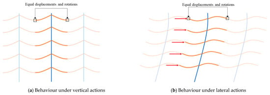
Figure 6.
Single-column model.
The model is well suited for vertical and horizontal actions (Figure 6a and Figure 6b, respectively). On the other hand, overturning or the behaviour of the lateral upright frames (those that only present beams on one side) cannot be captured; typically, additional flexural and torsional effects arise in those frames [6]. The use of such a model is aimed at simulating the behaviour of internal bays, and its use is endorsed by the high number of bays (Figure 5).
The steel of all the components was modelled as being linear elastic, with E = 210 GPa and υ = 0.3. The behaviour of floor and beam-to-upright joints is semi-rigid, presenting linear relationships between bending moment and rotation. Geometric nonlinearity was accounted for by co-rotational formulations in both beam and shell elements.
The load corresponding to the weight of the stored goods is uniformly distributed on the beams, resulting in 17/1.8 kN/m (Figure 5 and Figure 6a). Additionally, lateral forces of 47.6 N, related to the sway imperfections according to the standard EN15512 (ϕ = 1/350) [1], are applied at one half-span beam end, corresponding to the midspan point (Figure 6b). The self-weight of the steel is not considered, as it is negligible compared to the load of the stored goods.
The beam-to-upright joint was modelled by a sufficiently rigid assembly of bar elements (Figure 7) attached to the beam at point B (Figure 7b). Several couplings are placed between such an element and the upright, aiming to clamp the rotations with respect to X-X and Z-Z. Two uniaxial linear springs are placed at the top and bottom of such an assembly to model the rotational stiffness of the semi-rigid connection (Figure 7b). The springs are calibrated to have the same joint stiffness as that obtained from the code-type test [1], 160 × 106 Nmm/rad. The details of the modelling of this joint can be found in [26].
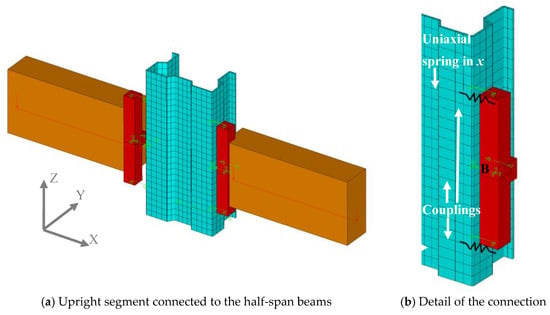
Figure 7.
Detail of the beam-to-upright joint model (the elements represented in orange and red correspond to the 3D beam finite elements, while the elements depicted in blue correspond to shell finite elements).
With respect to the floor connection, the nodes of the upright bottom section are linked to the rigid rotation of one node (O in Figure 8) with respect to the Y-Y axis, which simultaneously presents a rotational spring linked to a completely restrained node (OO in Figure 8); this rotational spring exhibits the stiffness obtained from the floor connection test [1], 139 × 106 Nmm/rad. In this modelling, X-X and Z-Z rotations at the floor are constrained, as well as warping. The modelling of the floor (Figure 8) and beam-to-upright (Figure 7) connections presented in this section is only valid for moderately small rotations [26].
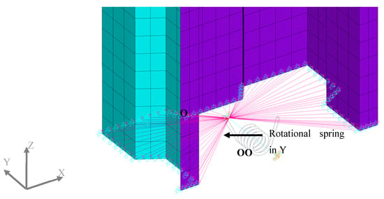
Figure 8.
Detail of the floor connection.
Diagonals of the upright frame were not modelled, but their constraining effect on the connecting upright sections is approximately accounted for. This is carried out by coupling the X displacement of the two points of the cross-section that connect with the bracing diagonal (Figure 9a). Moreover, the shear stiffness of the upright frame is approximately represented with uniaxial springs in the Y direction, placed between two consecutive diagonals (Figure 9b); the approximate (and rather imprecise) character of this modelling is acceptable when studying the down-aisle stability [4].
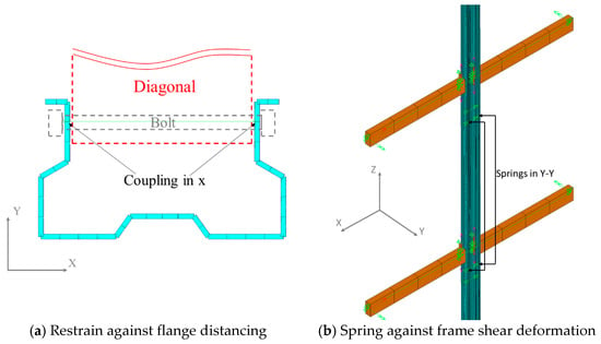
Figure 9.
Modelling of the retraining of uprights due to cross-aisle diagonal framing.
5. GBT Finite Element Model of the Structure
The GBT model also consists of one single upright with half-span beams connected at both sides. Only the 4 deformation modes related to global modes were used for the beam members. Notice that the torsional mode is obtained from the natural shear deformation mode set (closed section). On the other hand, 10 conventional modes and 24 modes (20 conventional and 4 local shear modes) were taken into account for perforated and non-perforated uprights, respectively. Perforations were modelled according to the GBT formulation defined in [19]. Sharp corners were considered in all cross-sections.
The structure is subjected to the same loading as the shell finite element model: a gravity load of 17/1.8 kN/m on the beams (Figure 5) and a lateral force of 47.6 N per load level at the column, corresponding to the sway imperfection. A cyclic symmetry condition is imposed between the two beam ends at each level, similar to FEM models (Figure 6b and Figure 10b). All deformation modes are completely restrained at the bottom of the upright elemental node, except for deformation mode 2 (Figure 11a), which is pinned. Additionally, a pure linear rotational spring for mode 2 with the value of 139 × 106 Nmm/rad is introduced to reproduce the connection semi-rigid behaviour. Noticeably, this rotational spring is the same type as those used in conventional beam finite element models of racks; thus, its stiffness was taken directly from the floor connection experimental test [1]. On the other hand, the beam-to-upright connection was modelled with constraint equations. First of all, the same rotations about the global X and Z axis (Figure 11a) between beam and upright nodes were introduced, taking into account the orientation of each member by means of Equations (9) and (10), respectively. Furthermore, the global displacements at the point where the connection is materialised (reference point in Figure 12) are coupled, considering only the global deformation modes. Equations (10)–(13) are the displacement coupling equations, which account for the location of the centroid and shear centre. Notice the and vectors consider the eccentricities between the reference point and the cross-section centroid and shear centre defined in the GBT beam elemental base (Figure 12), respectively. It is also important to point out that Equation (13) is defined in a global coordinate system; therefore, a rotation from elemental to a global base is carried out using Equations (11) and (12). Finally, a pure linear rotational spring (similar, once again, to those used in beam models) is defined between the beam and the upright GBT beam node with a value of 160 × 106 Nmm/rad to describe the semi-rigid behaviour of the connection. Detailed information on how the joints were modelled in GBT is described in [30].
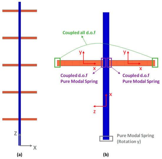
Figure 10.
(a) GBT structural model. Global coordinate system. (b) Detail of beam-to-upright connection and floor-to-upright connection and the GBT beam elemental basis for the upright and the beams.
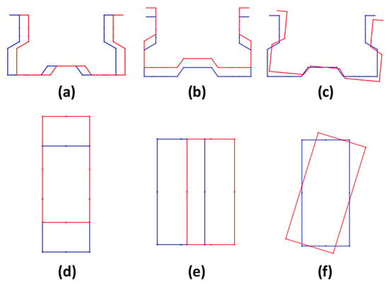
Figure 11.
Flexural and torsional global modes for the upright ((a) mode 2, (b) mode 3 and (c) mode 4) and the beam ((d) mode 2, (e) mode 3 and (f) mode 9) cross-section, respectively.
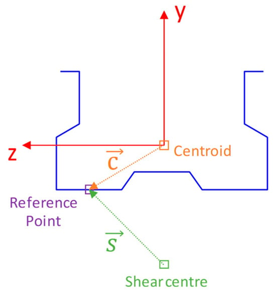
Figure 12.
GBT beam elemental basis for the upright cross-section. Schematics of the eccentricities determined between the reference point and centroid () and the reference point and the shear centre ().
The diagonals of the upright frame were not directly included in the model. However, their effects were considered by assuming a null Y displacement of the upright elemental nodes located at each beam level. Furthermore, an additional constraint equation was included: the X displacement (in the global coordinate system) of the two cross-sectional nodes where a bolt connects the upright to the diagonals are coupled (Figure 9a), reproducing the restrain of diagonals against symmetric distortion on the upright.
6. Validation of the GBT Finite Element Model
This section is aimed at validating the GBT model (Section 5) by comparing it with the shell model (Section 4). Perforated and non-perforated uprights are considered (Figure 13a and Figure 13b, respectively), with holes explicitly modelled with shells and accounted for in GBT throughout the formulation presented in [19]. Geometrically linear and nonlinear static analyses are applied.
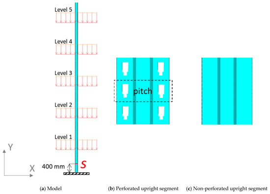
Figure 13.
Models for validation.
The following results are compared: (i) The lateral displacements in X direction at each loading level (Figure 13a); (ii) the longitudinal membrane stress distribution in an upright section found at 400 mm from the floor (section S in Figure 13a). The level displacements in X were selected because they were expected to be significantly influenced by the study parameters (presence of holes and geometric nonlinearity). On the other hand, section S was selected for being significantly demanded and for being far enough from the connections, whose modelling with GBT and shells is different, leading to possible localised differences.
Table 1 and Table 2 display the lateral displacements in X (mm) of each loading level (Figure 13a) for models with non-perforated and perforated columns, respectively. Results are displayed for geometrically linear and nonlinear analyses, as well as for the shell and GBT models. The column Diff. (%) presents the differences in percentage between shell and GBT results.

Table 1.
Displacement comparison between shell and GBT models with non-perforated uprights.

Table 2.
Displacement comparison between shell and GBT models with perforated uprights.
Table 1 shows small differences between the two models in geometrically linear analyses, except at the first level. A similar trend can be observed in the nonlinear analysis but with more significant differences. Remarkably, the absolute error remains rather constant (around 0.05 mm and 0.1 mm for linear and nonlinear analysis, respectively), resulting in the highest relative error at the lower level, where the displacement is small. The results obtained are reasonably accurate given the different modelling approaches applied for the joints and the restraining of the cross-aisle braces, as well as the limited number of modes included in the GBT analyses. The results in Table 2, corresponding to models with perforated uprights (Figure 13b), lead to similar observations.
Figure 14 displays the membrane stresses in the longitudinal direction on section S along its contour for both models obtained from the nonlinear analyses. Figure 14a,b, correspond to non-perforated and perforated column models, respectively. Noticeably, the continuity in section S is interrupted by the perforations that connect the upright with the diagonal braces. The results of GBT and shell models fit rather well when the upright has no perforations, with the differences slightly higher on the less compressed side of the upright. On the other hand, the differences in the model with a perforated upright are moderate and acceptable, except, as expected, near the perforations; this is because the GBT beam element formulation is not able to capture the stress concentrations near holes [19].
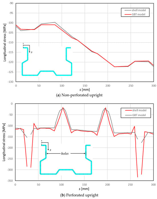
Figure 14.
Results from nonlinear analyses. Longitudinal stress distribution in S (Figure 11a).
7. Parametric Studies Conducted with the GBT Finite Element Model
Parametric analyses on fully loaded frames were performed to evaluate the influence of various modelling aspects on the internal force diagram, the stress distribution on the upright, and the displacement field of the structure. The single-column GBT model presented in the previous sections was used to conduct geometrically nonlinear analyses (GNIA).
7.1. Effect of Upright Sectional and Member Imperfections
First of all, the influence of initial upright sectional and member imperfections was assessed. The imperfections were created as a combination of the down-aisle out-of-plumb (S: sway, equivalent forces approach), plus one or two of the following imperfections: SD (symmetric distortional), AD (anti-symmetric distortional), T (twist) and B (bow—Figure 11b). Noticeably, with the aim of reducing the number of analyses to be carried out in the parametric study, the camber imperfection mode (Figure 11a) was omitted; it was considered that the twist imperfection already triggers bending member deformations in the down-aisle direction. For the same reason of reducing the number of analyses, distortional buckling was the only contemplated sectional initial deformation. No local buckling imperfection was applied since, typically, the local deformation mode does not govern the behaviour of multi-stiffened rack sections, such as the one used in the example under analysis. On the other hand, bow member imperfection was included because it commonly produces rather detrimental effects in the axial capacity when combined with the symmetric distortional one.
A maximum magnitude of L/1000 was defined for the pure member imperfection (bow and torsional modes), while two different magnitudes were applied for pure distortional imperfections: t and 0.25 t. These values are within the range of commonly used imperfection magnitudes [31]. The shapes of these pure sectional and member imperfections (Figure 15) were obtained by means of GBT eigenbuckling analyses involving only member global or distortional deformation modes. Finally, the initial member imperfection was defined as a linear combination of these pure member imperfections. As a result, the 13 different initial geometrical imperfections shown in Table 3 were evaluated. The direction of each pure member imperfection (+ or −) is defined according to the shape of the eigenbuckling mode. It is important to point out that only one out-of-plumb direction is considered (positive) and that all the combinations of positive and negative imperfections will produce different results in the nonlinear analyses since out-of-plumb is asymmetrical. The shape of two different types of combined member imperfections is shown in Figure 16.
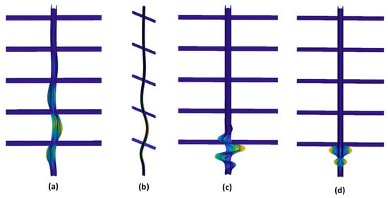
Figure 15.
Shape of a pure twist/torsion (a), bow (b), anti-symmetric distortional (c), and symmetric distortional member imperfection (d). The magnitude of the imperfection modes has been magnified for easier observation.

Table 3.
Imperfection magnitudes (mm) of the pure member modes and combinations.
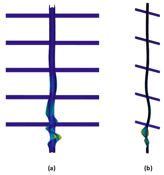
Figure 16.
Shape of (a) S/T−/AD1− and (b) S/B+/SD1+ member imperfection (the magnitude of the imperfection modes has been magnified for easier observation).
The results of all GBT geometrically nonlinear analyses are compared in Table 4. Firstly, similar global lateral displacement values are observed in all cases. Differences in displacements are only significant at the member level (in the segments of the uprights between joints). These differences lead to major changes in other aspects of the rack behaviour. Specifically, the longitudinal membrane stress distribution clearly changes between simulations. The results indicate that adding a distortional member imperfection produces significantly higher maximum longitudinal membrane stress values, especially when the highest distortional member imperfection magnitude is used (t). Similarly, and as a consequence, the internal forces are also found to depend on the imperfection shape and magnitude. The sensitivity of the flexural (camber) and warping torsional (bi-moment) internal moments diagrams to the imperfections is shown in Figure 17 and Figure 18 and Figure 19 and Figure 20, respectively. Remarkably, the effect of the imperfections on the warping torsional moment can be significant (see Figure 19).

Table 4.
Comparison of maximum lateral displacement and maximum compressive longitudinal membrane stress of the rack column.
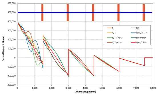
Figure 17.
Flexural moment internal force diagram along the column length according to the type of initial geometrical imperfection with a sectional member amplitude of t.
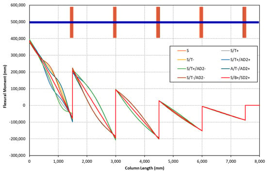
Figure 18.
Flexural moment internal force diagram along the column length according to the type of initial geometrical imperfection with a sectional member amplitude of 0.25 × t.
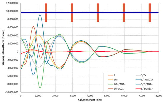
Figure 19.
Warping torsional moment (bi-moment) diagram along the column length according to the type of initial geometrical imperfection with a sectional member amplitude of t.
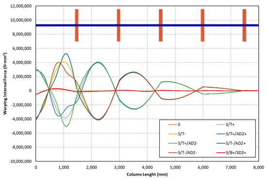
Figure 20.
Warping torsional moment (bi-moment) diagram along the column length according to the type of initial geometrical imperfection with a sectional member amplitude of 0.25 × t.
It is noted that the analyses were carried out considering the most relevant member and sectional GBT deformation modes. It was observed that the most significant changes in the analysis results are not caused by whether a deformation mode is active or not but rather by the inclusion of its corresponding imperfection. For instance, a comparison of the results obtained with AD1 and AD2 imperfection magnitudes in Table 4 illustrates this point. It can be concluded that imperfections are important in activating the distortional modes. This may be a consequence of the particular characteristics of the structure being analysed, GBT model simplifications applied and type and level of loading, as briefly discussed in the last section of the article.
One of the main trademarks of GBT is its modal nature, which allows assessing the influence of each deformation mode on the stress distribution of the rack frame column. A stress ratio value (SRi) (Equation (14)) is determined for each deformation mode, where |σMi| corresponds to the maximum longitudinal membrane stress (in modulus) caused by mode i.
The comparison of the stress ratio values among different member imperfections is presented in Table 5. First of all, the results indicate that the longitudinal membrane stress distribution is mainly dominated by the axial and camber flexural mode for the GBT nonlinear analysis without distortional imperfections. The effect of the inclusion of GBT distortional modes seems to be small if only the out-of-plumb (S) and torsional imperfections (T) are taken into account. As discussed above, the influence on the longitudinal membrane stress distribution of torsion and distortional modes clearly depends on the inclusion of distortional imperfections as well as their magnitude. The influence of the AD imperfection is remarkable. Concerning the values in Table 5, it is important to point out that the maximum stress value of each deformation mode can occur at a different location of the column; therefore, the maximum longitudinal stress value cannot be directly calculated as the sum of the maximum values of each deformation mode. The longitudinal membrane stress distributions according to each deformation mode are presented in Figure 21. This distribution is obtained for the rack column between the floor and the first beam and for the S/T−/AD1− initial member imperfection.

Table 5.
Stress ratios SRi (Equation (14)) of the most meaningful sectional modes.
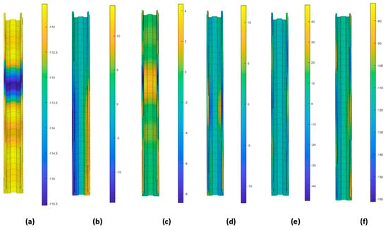
Figure 21.
Longitudinal membrane stress distribution (S/T−/AD1− member imperfection) of the (a) axial, (b) camber, (c) bow, (d) twist, (e) distortional modes, and (f) with all deformation modes involved in the analysis.
7.2. Effect of Floor Connection Boundary Conditions
The characteristics of the upright-to-floor connection play a relevant role in the structural behaviour of pallet rack structures in the down-aisle direction. Commonly, this connection presents a semi-rigid flexural behaviour, and it is modelled with a rotational spring (linear or nonlinear). Furthermore, its stiffness (moment–flexural rotation) depends on the upright axial internal force. Thus, several experimental tests are carried out at different axial load levels. On the other hand, although the sectional deformation of the cross-section is usually restrained at the upright-to-floor connection, the warping degree of freedom can present diverse levels of constrain (from free to completely restrained), depending on its design characteristics. Consequently, additional analyses with free warping displacement (for torsional and distortional modes) of the column cross-section at the floor connection were carried out to study the sensitivity of the model results.
In these additional analyses, the sectional and member imperfections of the rack column were obtained following the same procedure described in Section 7.1, but with released warping at the upright bottom section. Notice that the shape of these imperfections can be different than those presented in Figure 15 due to the change in the boundary conditions. The shape and magnitude of the imperfections can be observed in Figure 22a,b and Table 6; Figure 22c displays the resulting warping torsional moment diagrams. The main results of these analyses are shown in Table 7 and Table 8, similarly to Table 4 and Table 5.
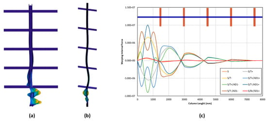
Figure 22.
The shape of (a) S/T-/AD1- and (b)S/B+/SD1+ member imperfection with the free warping degree of freedom at the upright-to-floor connection. (c) Warping torsional moment diagram along the column length with the free warping degree of freedom at the upright-to-floor connection.

Table 6.
Imperfection magnitudes (mm) of the pure member modes and combinations. Load case with a free warping degree of freedom at the floor column cross-section.

Table 7.
Maximum lateral displacement and maximum compressive longitudinal membrane for the case with free warping at the floor column cross-section.

Table 8.
Stress ratios (SRi in Equation (14)) values for free warping degree of freedom at the floor column cross-section.
The change in the boundary conditions seems to have a marginal effect on the maximum global sway displacement. Contrarily, higher maximum membrane longitudinal stress values were obtained for the combined imperfections with the larger sectional magnitude (t). Concerning internal forces, bending moment diagrams are similar, whereas the warping torsional moment diagrams are clearly different for the first part of the upright, which was expected due to the effect of the new boundary conditions (Figure 22c). As a result, some differences were found in the influence of deformation modes on the maximum longitudinal stress value, where torsional and distortional modes present a relevant role, as observed in Table 8. However, conclusions on the effects of imperfections and other aspects of the model are similar to those derived in the previous section.
7.3. Effect of Perforations
The influence of perforations has also been assessed. Additional GBT geometrically nonlinear analyses, including upright perforations, have been carried out. The characteristics of the applied initial geometrical imperfections are described in Table 9. In order to reduce the number of analyses, only the negative twist member imperfection (T-) is considered when combined with sectional imperfections because it results in higher lateral displacements. The same procedure is used to obtain the shape and magnitude of the combined imperfections. However, some differences are found, especially when sectional deformations are included because slightly different eigenshapes are obtained for perforated members. Finally, it is noted that the warping degree of freedom at the floor column cross-section is completely restrained (as in Section 7.1).

Table 9.
Imperfection magnitudes (mm) of the pure member modes and combinations. Perforated uprights.
The main results are shown in Table 10 and Table 11. The increase in lateral displacement due to perforations is small. Contrarily, the maximum longitudinal membrane stress is larger. This is an expected result since perforations decrease the section area and modulus of the column. Furthermore, differences between longitudinal membrane stress distribution are still found for different types of initial imperfection, especially in the cross-section lips, as shown in Figure 23. However, the differences between the maximum longitudinal stress values (in modulus) obtained for the different imperfection combinations are clearly lower for the perforated than for the non-perforated rack column. This is because the maximum stress value is obtained around a web perforation.

Table 10.
Comparison of maximum lateral displacement and maximum compressive longitudinal membrane stress of the perforated rack column.

Table 11.
Stress ratios (SRi in Equation (14)) of model with perforations.
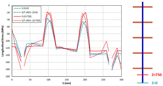
Figure 23.
Longitudinal membrane stress distribution at two different cross-sections (Z = 0 and Z = 750 mm) according to the initial member imperfection.
On the other hand, in Table 11 (and Figure 24), it can also be observed that the influence of distortional modes on the longitudinal membrane stress distribution seems to be slightly more relevant for perforated members. This can be explained by the fact that, in the particular rack column under study, the inclusion of perforations reduces the stiffness of those distortional deformation modes that play a relevant role in the deformed shape.
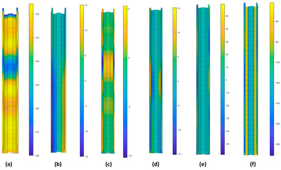
Figure 24.
Longitudinal membrane stress distribution (S/T-/AD1-/Perf member imperfection) of the (a) axial, (b) chamber, (c) bow, (d) twist, (e) distortional modes, and (f) with all deformation modes involved in the analysis.
8. Advantages of GBT in the Modelling of Down-Aisle Rack Frames
Before moving on to the concluding remarks of this study, it is worth highlighting the main advantages encountered during the analyses of the rack frame with GBT when compared to standard beam and shell finite element analyses:
- The model of the structure is easily created in a similar manner to that of any model using conventional beams.
- The warping degree of freedom is inherently incorporated in the beam element formulation.
- The effect of local and distortional deformations on the global behaviour of the structure can be accounted for without requiring a shell finite element model, which usually involves higher modelling costs. Additionally, the use of the reduction stiffness factors typically applied in beam models to consider such effects is unnecessary. If material nonlinearity had been incorporated into the analysis, the effect of local plasticity could also be addressed.
- Similarly, the effect of perforations is considered through a rigorous formulation. There is no need to use equivalent reduced thicknesses or properties of the cross-section.
- GBT enables the individual activation of each deformation mode and its corresponding imperfection. Consequently, (i) the effect of each individual, or type of, deformation mode can be independently investigated. For instance, it can be known the contribution of a deformation mode to the total stress at a specific point of a structure; (ii) GBT facilitates the introduction of pure imperfection shapes, such as pure torsional or distortional imperfections. This can be performed in a straightforward manner, without the need for indirect strategies.
- Torsional warping (as well as other warping deformations) can be independently and easily constrained, or left unconstrained, at the connections. This is more difficult in shell finite element models.
- The simplicity of the beam-to-column and floor joint models can be similar to that of beam finite element models. As a consequence, the moment–rotation curve derived from experimental tests can be directly implemented in the global analysis using rotational linear or nonlinear springs. Modelling rack joints with shell finite elements is significantly more complex.
- In GBT, the same model can be used to easily derive both beam type results, such as internal forces, and shell-type results, such as stresses. Consequently, it can be used, for instance, in both a design based on GNIA with checks against standard formulations, and a “direct” design based in GMNIA.
It should be noted that material nonlinearity is not considered in the present investigation. As a consequence, the authors have not verified the advantages mentioned above concerning the plasticity effects and GMNIA, nor are they aware of the potential computational costs that may be associated. Contrarily, they can confirm that the computational cost of the GBT analyses presented throughout this work is similar to that of beam models.
9. Conclusions
This paper presented a GBT beam model of a pallet rack down-aisle frame. The model was simplified to a single column to reduce the modelling and computational costs; however, it accounts for the main factors determining the performance of the structure: perforations, beam-to-column and floor joint behaviour, eccentricities with respect to the centroid and shear centre, imperfections, sectional deformations, warping torsion, and geometric nonlinearity (material nonlinearity was not included).
The GBT model was validated against a shell finite element simulation. It is noteworthy that despite some significant differences in modelling considerations, particularly regarding joints and perforations, the GBT model demonstrated remarkable agreement with the shell FEM model in terms of sway displacements and section stresses.
A parametric study was carried out with the validated GBT model to investigate the effect of imperfections, support conditions and perforations. The main conclusions of the study are as follows:
- It was observed that distortional imperfections were needed to trigger the sectional deformations.
- The effect of the sectional deformations and corresponding imperfections seemed important on individual members, i.e., column segments between beams. Their influence on the horizontal displacements of the joints was minimal. Consequently, the global sway displacement of the structure did not significantly change.
- The most important effect of activating sectional deformations, achieved by introducing sufficiently large imperfections, was the increase in the warping torsional moment (the commonly known bi-moment) and its corresponding stresses, along with distortional stresses.
- Modifying the warping support of the floor joint resulted in significant changes to the warping torsional moment and the warping torsional and distortional stresses, but only at the first column level.
- The introduction of the perforations had a small effect on the global sway displacement.
- The reduced net area of the perforated members provoked the expected stress increase.
- In perforated members, while the stress distribution changes depending on the distortional imperfections considered, their influence on the maximum membrane stress is small due to the effects of stress concentration.
It is important to emphasise that these concluding remarks are based on a specific structural design with a particular force pattern, predominantly consisting of gravitational loads. It is expected that these results may suffer important changes in other situations. For instance, (i) the role of distortional imperfections in activating the effect of sectional deformations may be less important if triggered by a more realistic GBT modelisation of the joints, or if a higher load level is used, causing the structure to approach the elastic or plastic collapse where sectional deformations become more relevant; (ii) increasing the distance between levels will increase the slenderness of both the individual members and the global structure, leading to greater geometric nonlinear effects in general, and particularly larger sensitivity of the global sway displacements to distortional imperfections and perforations; (iii) the opposite effect will occur if the structure is braced in the down-aisle direction; or (iv) considering higher horizontal loads (such as seismic action) may also change the behaviour concerning sectional deformations and sway displacements. Overall, this article presents only the initial phase of the research and the potential utility of GBT, but there are still aspects to be explored in future studies.
Author Contributions
Conceptualization: J.B., O.B., M.C.; Methodology: J.B., O.B., M.C.; Software: J.B., O.B.; Investigation: J.B., O.B., M.C., I.L.-R.; Writing—original draft preparation: J.B., O.B., M.C.; Writing—review and editing: I.L.-R.; Supervision: M.C. All authors have read and agreed to the published version of the manuscript.
Funding
This research received no external funding.
Data Availability Statement
The raw data supporting the conclusions of this article will be made available by the authors on request.
Conflicts of Interest
The authors declare no conflict of interest.
References
- EN 15512; Steel Static Storage Systems—Adjustable Pallet Racking Systems—Principles for Structural Design. European Committee for Standardization (CEN): Brussels, Belgium, 2020.
- ANSI MH16.1; Design, Testing, and Utilization of Industrial Steel Storage Racks, Rack Manufacturers Institute (RMI). American National Standards Institute (ANSI): New York, NY, USA, 2021.
- AISI S100-16; North American Specification for the Design of Cold-Formed Steel Structural Members. (2020 w/S3-22). American National Standards Institute (ANSI): New York, NY, USA, 2020.
- Cardoso, F.S.; Rasmussen, K.J. Finite element (FE) modelling of storage rack frames. J. Constr. Steel Res. 2016, 126, 1–14. [Google Scholar] [CrossRef]
- Bernuzzi, C.; Montanino, A.; Simoncelli, M. Torsional behaviour of thin-walled members with regular perforation systems. ce/papers 2021, 4, 343–350. [Google Scholar] [CrossRef]
- Bernuzzi, C.; Gobetti, A.; Gabbianelli, G.; Simoncelli, M. Warping influence on the resistance of uprights in steel storage pallet racks. J. Constr. Steel Res. 2014, 101, 224–241. [Google Scholar] [CrossRef]
- Bernuzzi, C.; Pieri, A.; Squadrito, V. Warping influence on the static design of unbraced steel storage pallet racks. Thin-Walled Struct. 2014, 79, 71–82. [Google Scholar] [CrossRef]
- Bernuzzi, C.; Gobetti, A.; Gabbianelli, G.; Simoncelli, M. Unbraced pallet rack design in accordance with European practice–Part 1: Selection of the method of analysis. Thin-Walled Struct. 2015, 86, 185–207. [Google Scholar] [CrossRef]
- Bernuzzi, C.; Gobetti, A.; Gabbianelli, G.; Simoncelli, M. Unbraced pallet rack design in accordance with European practice–Part 2: Essential verification checks. Thin-Walled Struct. 2015, 86, 208–229. [Google Scholar] [CrossRef]
- Teh, L.H.; Hancock, G.J.; Clarke, M.J. Analysis and Design of Double-Sided High-Rise Steel Pallet Rack Frames. J. Struct. Eng. 2004, 130, 1011–1021. [Google Scholar] [CrossRef]
- Bernuzzi, C.; Simoncelli, M. EU and US design approaches for steel storage pallet racks with mono-symmetric cross-section uprights. Thin-Walled Struct. 2017, 113, 181–204. [Google Scholar] [CrossRef][Green Version]
- Liu, S.W.; Pekoz, T.; Gao, W.L.; Ziemian, R.D.; Crews, J. Frame analysis and design of industrial rack structures with perforated cold-formed steel columns. Thin-Walled Struct. 2021, 163, 107755. [Google Scholar] [CrossRef]
- Gao, W.L.; Liu, S.W.; Pekoz, T.; Ziemian, R.D.; Crews, J. Dynamic Analysis and Seismic Responses of Industrial Rack Structures with Perforated Cold-formed Steel Columns using Line Elements. In Proceedings of the Cold-Formed Steel Research Consortium Colloquium (cfsrc.org), Online, 20–22 October 2020. [Google Scholar]
- Trouncer, A.N.; Rasmussen, K.J. Ultra-light gauge steel storage rack frames. Part 2–Analysis and design considerations of second order effects. J. Constr. Steel Res. 2016, 124, 37–46. [Google Scholar] [CrossRef]
- Cardoso, F.S.; Rasmussen, K.J.; Zhang, H. System reliability-based criteria for the design of steel storage rack frames by advanced analysis: Part I–Statistical characterisation of system strength. Thin-Walled Struct. 2019, 141, 713–724. [Google Scholar] [CrossRef]
- Sarawit, A.T. Cold-Formed Steel Frame and Beam-Column Design. Cornell University: Ithaca, NY, USA, 2003. [Google Scholar]
- Tilburgs, K. Those peculiar structures in cold-formed steel: “Racking & shelving”. Steel Constr. 2013, 6, 95–106. [Google Scholar]
- Rasmussen, K.J.R.; Gilbert, B.P. Analysis-Based Design Provisions for Steel Storage Racks. J. Struct. Eng. 2013, 139, 849–859. [Google Scholar] [CrossRef]
- Bonada, J.; Casafont, M.; Roure, F.; Pastor, M. Geometrically nonlinear analysis of perforated rack columns under a compression load by means of Generalized Beam Theory. Thin-Walled Struct. 2021, 166, 108102. [Google Scholar] [CrossRef]
- Gonçalves, R.; Camotim, D.; Basaglia, C.; Martins, A.D.; Peres, N. Latest developments on the analysis of thin-walled structures using Generalised Beam Theory (GBT). J. Constr. Steel Res. 2023, 204, 107858. [Google Scholar] [CrossRef]
- Basaglia, C.; Camotim, D.; Silvestre, N. Global buckling analysis of plane and space thin-walled frames in the context of GBT. Thin-Walled Struct. 2007, 46, 79–101. [Google Scholar] [CrossRef]
- Camotim, D.; Basaglia, C.; Silvestre, N. GBT buckling analysis of thin-walled steel frames: A state-of-the-art report. Thin-Walled Struct. 2010, 48, 726–743. [Google Scholar] [CrossRef]
- Basaglia, C.; Camotim, D.; Silvestre, N. Post-buckling analysis of thin-walled steel frames using generalised beam theory (GBT). Thin-Walled Struct. 2012, 62, 229–242. [Google Scholar] [CrossRef]
- Manta, D.; Gonçalves, R.; Camotim, D. Combining shell and GBT-based finite elements: Linear and bifurcation analysis. Thin-Walled Struct. 2020, 152, 106665. [Google Scholar] [CrossRef]
- Manta, D.; Gonçalves, R.; Camotim, D. Combining shell and GBT-based finite elements: Plastic analysis with adaptive mesh refinement. Thin-Walled Struct. 2020, 158, 107205. [Google Scholar] [CrossRef]
- Bové, O.; Casafont, M.; Bonada, J.; Ferrer, M.; López-Almansa, F. Investigation on the down-aisle ductility of multiple bay pallet racks by means of pushover analyses. Eng. Struct. 2023, 286, 116085. [Google Scholar] [CrossRef]
- ANSYS. Release 19.0; ANSYS Inc.: Canonsburg, PA, USA, 2019. [Google Scholar]
- Godley, M.H.R.; Beale, R.G.; Feng, X. Analysis and design of down-aisle pallet rack structures. Comput. Struct. 2000, 77, 391–401. [Google Scholar] [CrossRef]
- Bové, O.; Casafont, M.; Ferrer, M.; Lópèz-Almansa, F.; Roure, F. Systematized structural predesign method for selective racks. J. Struct. Eng. 2020, 146, 04020276. [Google Scholar] [CrossRef]
- Bonada, J.; López, I.; Bové, O.; Casafont, M. Modelling of pallet rack connections by means of a geometrically nonlinear analysis based on the Generalized Beam theory. Unpublished work. 2024. [Google Scholar]
- Pastor, M.; Casafont, M.; Bonada, J.; Roure, F. Imperfection amplitudes for nonlinear analysis of open thin-walled steel cross-sections used in rack column uprights. Thin-Walled Struct. 2014, 76, 28–41. [Google Scholar] [CrossRef]
Disclaimer/Publisher’s Note: The statements, opinions and data contained in all publications are solely those of the individual author(s) and contributor(s) and not of MDPI and/or the editor(s). MDPI and/or the editor(s) disclaim responsibility for any injury to people or property resulting from any ideas, methods, instructions or products referred to in the content. |
© 2024 by the authors. Licensee MDPI, Basel, Switzerland. This article is an open access article distributed under the terms and conditions of the Creative Commons Attribution (CC BY) license (https://creativecommons.org/licenses/by/4.0/).