Article

Electrospray Nested Energetic Cells from Nanothermite with MoO3 Nanostrips: Reactivity, Sensitivity and Combustion Performance

1
State Key Laboratory of Precision Blasting, Jianghan University, Wuhan 430056, China
2
China State Key Laboratory of Explosion Science and Technology, Beijing Institute of Technology, Beijing 100081, China
*
Author to whom correspondence should be addressed.
Appl. Sci. 2024, 14(13), 5522; https://doi.org/10.3390/app14135522
Submission received: 15 May 2024 / Revised: 21 June 2024 / Accepted: 22 June 2024 / Published: 25 June 2024
(This article belongs to the Section Materials Science and Engineering)

Abstract

:
Nanothermites have attracted great attention over the last two decades for their superior performance in heat release and pressure wave generation. The shape of the oxidizer and the assembly structure could significantly influence the performance. This paper reports on the reactivity, sensitivity and combustion performance of nanothermite of aluminum nanoparticles and MoO3 nanostrips prepared via electrospray strategy. The resulting particles were in good integrity, resembling bird nests. There were two exothermic processes for the resulting composites, which successively conformed to the Avrami–Erofeev equation of n = 4 and the Zhuravlev–Lesokhin–Tempelman (Z-L-T) equation. And the corresponding activation energies for the two processes were 148.645 kJ/mol and 297.280 kJ/mol, respectively. The flame sensitivity and impact sensitivity for the electrosprayed product were 50 cm and 35 cm, respectively, which were both higher than those of the mechanically mixed counterpart. The constant-volume combustion test showed that the maximum pressure of the electrosprayed product was 1.96 MPa, which was 0.69 MPa higher than that of the mechanically mixed counterpart. The combustion performances were evaluated under confined and unconfined conditions. Due to the fast heat release and transfer efficiency, fierce deflagration was achieved in the case of the electrosprayed sample under confined conditions. The combustion rate of the electrosprayed sample under unconfined conditions was almost a hundred times as much as that of the mechanically mixed one.

1. Introduction

Thermites are a mixture of metallic and oxide powders, which are widely used in the military and civil applications [1,2,3,4,5]. Thermite reactions will release a large amount of heat and provide a high combustion temperature. Therefore, thermite powders could not only serve as pyrotechnics, but could be added into explosive formulations to improve the energy densities. More recently, the fragmentation of rock masses via thermites has been reported besides traditional welding applications [6]. A thermite reaction generates less noise and ground vibrations than explosive blasting, which benefits the protection of the surrounding facilities.
The thermite reaction usually initiates in the solid–solid phase with a slow reaction rate due to the high melting point of most metal oxides. With the appearance of the gas phase, the system pressure will be substantially elevated, resulting in a higher reaction rate [7]. Hence, oxidizers of low melting points, such as MoO3, BaO and Bi2O3, are favorable for the application of pressure wave generations [8]. In addition, the enthalpy of a reaction between MoO3 and aluminum particles is the highest among oxidizers of low melting points. Therefore, MoO3 has become one of the most popular metal oxides for thermites [9,10,11].
The reaction performance of thermites depends not only on the size, shape and nature of the oxidizer/metal, but on the assembly structure [12,13,14,15,16]. Wang et al. [16] used iron fluoride as an oxidizer to prepare thermite, and the resulting product showed higher reactivity but lower reaction heat release than thermite with iron oxide. Li et al. [17] employed a bimetal system (Al/Ni) in the thermite formulation, leading to a decrease in the combustion temperature. With the size of the reactants reduced to nano-scale, the reaction rate of thermite could be significantly accelerated [18,19]. However, nanoparticles tend to agglomerate together due to the high specific surface area, leading to a heterogeneous blend, which will weaken the size effect. Therefore, micro-structure assembly techniques, such as electrospray [20], the sol-gel method [21,22], microfluidic method [23] and 3D printing strategy [24], have been widely developed over the last few years. These efforts aim to achieve the ultimate goal, i.e., assembled structures’ maintenance of the nano-scale characteristics as well as good flowability and processibility [25].
Binders are necessary with respect to micro-structure assembly. They not only help bond the reactants together to form an intact structure, but also provide a direct heat and mass transfer path [26,27]. The influence of fluoropolymers as a binder has been extensively studied due to the pre-ignition effect between the fluorine element and aluminum [20,28,29,30]. However, fluoropolymers would not benefit the energy release until they react with aluminum particles. On the contrary, energetic polymers are more active than fluoropolymers. The reaction of energetic polymers is ahead of a thermite reaction. What is more, the energy density of thermite would also be increased by the energetic polymer [30,31,32]. When it comes to the heat release, the reaction rate matters the most. And the reaction rate is controlled by heat and mass transfer efficiency. A recent study has revealed that stacks assembled by hybrid 2D- and 3D-shaped particles owe a better heat transfer efficiency than those by single-shape alignment [33,34].
Although many studies have been performed to improve the performance of nanothermite, the energy release of nanothermite is still undesirable due to the sintering of aluminum particles which will cause an incomplete reaction [35]. To solve this problem, we changed the stack structure of oxidizer and aluminum particles in the hope to improve the heat transfer efficiency. Additionally, an energetic binder was incorporated to prevent sintering, as well as improve the energy density. The objective of this work is to study the reaction performance of nanothermite with 3D aluminum particles and 2D oxidizer. Based on that, the feasibility of the nanothermite serving as a nontoxic primer is evaluated with respect to sensitivities, pressurization rate, and burning rate. The nanothermite is prepared via the electrospray strategy, with nitrocellulose (NC) as the binder.

2. Experimental

2.1. Synthesis of MoO3 Nanostrips

The synthesis of MoO3 nanostrips has been performed by the hydrothermal strategy. The ammonium paramolybdate solution (concentration of 0.06 mol·L−1) was prepared by dissolving ammonium paramolybdate (AR, Tianjin No.4 Chemical Reagent Plant, Tianjin, China) in ultrapure water under agitation and further adjustment in a constant-volume bottle. Then, the dilute nitric acid (concentration of 2.88 mol·L−1) was added dropwise into the solution at a proportion of 3:4 in volume to achieve an acidity coefficient of 64 under vigorous stirring. The above mixture was transferred into a poly(tetrafluoroethylene)-lined autoclave (volume 100 mL, Beijing Ruicheng Weiye instrument Co., Ltd., Beijing, China). Hydrothermal syntheses were performed at 150 °C for 48 h. The products of the hydrothermal syntheses were isolated by suction filtration and further washed successively with distilled water and ethanol for several times. After that they were dried up in a vacuum drying oven at 100 °C for 10 h.

2.2. Precursor Preparation

In the precursor, NC was employed to be the binder. The NC (N% = 10.9) was acquired from a drying collodion solution (4–8 wt.% NC in ethanol and diethyl ether, Damao Chemical Reagent Co. Ltd., Tianjin, China). Before using, the NC was homogeneously dissolved in a mixture solvent of ethanol and diethyl ether at a volume ratio of 1:1 by vigorous agitation for 1 h. In the typical precursor preparation process, first, the Al nanoparticles (~100 nm, Beijing Deke Daojin Science and Technology Co., Ltd., Beijing, China) and MoO3 nanostrips (mAl:mMoO3 = 3:8) were homogenously dispersed in the mixture solvent of acetone and ethanol (the ratio was 1:1 in volume) by agitation for 2 h; then, the NC solution was added to the above-mentioned mixture with the help of a pipette under stirring conditions, followed by ultrasonic agitation for 12 h to obtain the homogenous and steady precursor.

2.3. Electrospray Fabrication of Al/MoO3 Nanothermite

The diagram of the electrospray fabrication of Al/MoO3 nanothermite is dipicted in Figure 1. The electrospray process was conducted by a self-made electrospray apparatus, in which a syringe of 20 mL with a stainless steel nozzle (inner diameter: 0.8 mm) was used to load the precursor. And the flow rate of the precursor was set to be 4 mL·h−1, which was determined by a syringe pump. The nozzle was connected to the anode of a high-voltage power supply, and the working voltage was set to be 20 kV. An aluminum foil supported by a planar iron plate served as the collector, which connected to the cathode of the high-voltage power supply. The nozzle was 10 cm above the collector. The electrosprayed products were denoted as Al/MoO3-E. To make a comparison, the mechanically mixed counterpart was also prepared by dispersing Al and MoO3 in the same mixture solvent, and vigorously stirred for 2 h. Then, the blend was filtrated and after that, the mixture was dried in the vacuum oven for 4 h. The resulting mixture was denoted as Al/MoO3-M.

2.4. Sample Characterizations

The surface morphology and elemental composition of the samples were observed by a field emission scanning electron microscope (FESEM, Hitachi S-4800, Tokyo, Japan) coupled with an energy-dispersive spectrometer (EDS, EDAX Octane SDD, Pleasanton, CA, USA), at an accelerating voltage of 15 kV. Before testing, all the samples were sputtered with gold on the surface by an ion sputtering device. Infrared spectra were obtained by Fourier transform infrared spectroscopy (FTIR, Bruker VERTEX 70, Karlsruhe, Germany) over a range of 4000 to 400 cm−1.
The thermochemical behaviors of the samples were investigated by a simultaneous differential scanning calorimetry–thermogravimetry instrument (DSC-TG, Netzsch STA449F3, Selb, Germany) under an air/argon flow rate of 50 mL·min−1 from room temperature to 700 °C. The mass of the sample for each test was 2 ± 0.02 mg, which was loaded in an alumina crucible. The thermodynamic properties of the samples were analyzed based on the DSC-TG results measured at the heating rates of 5 °C·min−1, 10 °C·min−1, 15 °C·min−1, 20 °C·min−1 and 25 °C·min−1.

2.5. Sensitivity Tests

The impact sensitivities of the samples were acquired by the drop-weight impact test. In a typical test, a weight of 1.2 kg was dropped from a predefined height onto a striker plate. The next height was determined by the result of the last test: if a reaction happened in the last test, the next height would be decreased, otherwise it would be increased. A sequence of tests were conducted until the sensitivity index, H50, was acquired [36]. Here, the H50 was the height at which a given weight dropped onto the sample produced a reaction of 50% of the test trails. The diagram of the test equipment is shown in Figure 2a.
The flame sensitivities of the samples were measured using the up and down method [37]. In a typical test, twenty milligrams of the sample was placed in a copper cap and was ignited by a black powder pellet. And the flame sensitivity (H50) for 50% probability of ignition was calculated. The diagram of the test equipment is shown in Figure 2b.

2.6. Combustion Performances

The constant volume combustion tests were performed in a confined-volume chamber of 13 mL. Then, 0.1 ± 0.005 g of the thermite composites was used for each test. Thermite composites were ignited by a nichrome wire (ϕ0.2 mm × 90 mm) which was connected to an electric source with a rated voltage of 12 V. The measurements were conducted under the environment temperature of 25 °C. The tests were conducted under vacuum conditions. Each sample was tested at least three times.
Combustion under confined conditions was conducted in an open-end PMMA tube (ϕ4 mm × 70 mm) under ambient air. The density of the test sample was kept as ~0.53 g·cm−3. The samples were ignited by an electric igniter. And the combustion process was recorded by a high-speed camera (Photron SIMD8, Tokyo, Japan) at a rate of 1500 fps.
To preclude the fierce deflagration of Al/MoO3-E, the combustion velocity of the sample was measured under unconfined conditions. For each test, 0.2 g of the sample was loosely placed on a flat slab in the shape of 20 cm × 5 cm × 0.5 cm. The sample was ignited by an electric igniter. And the combustion process was recorded by a high-speed camera (Photron SIMD8, Japan) at a rate of 1500 fps.

3. Results and Discussion

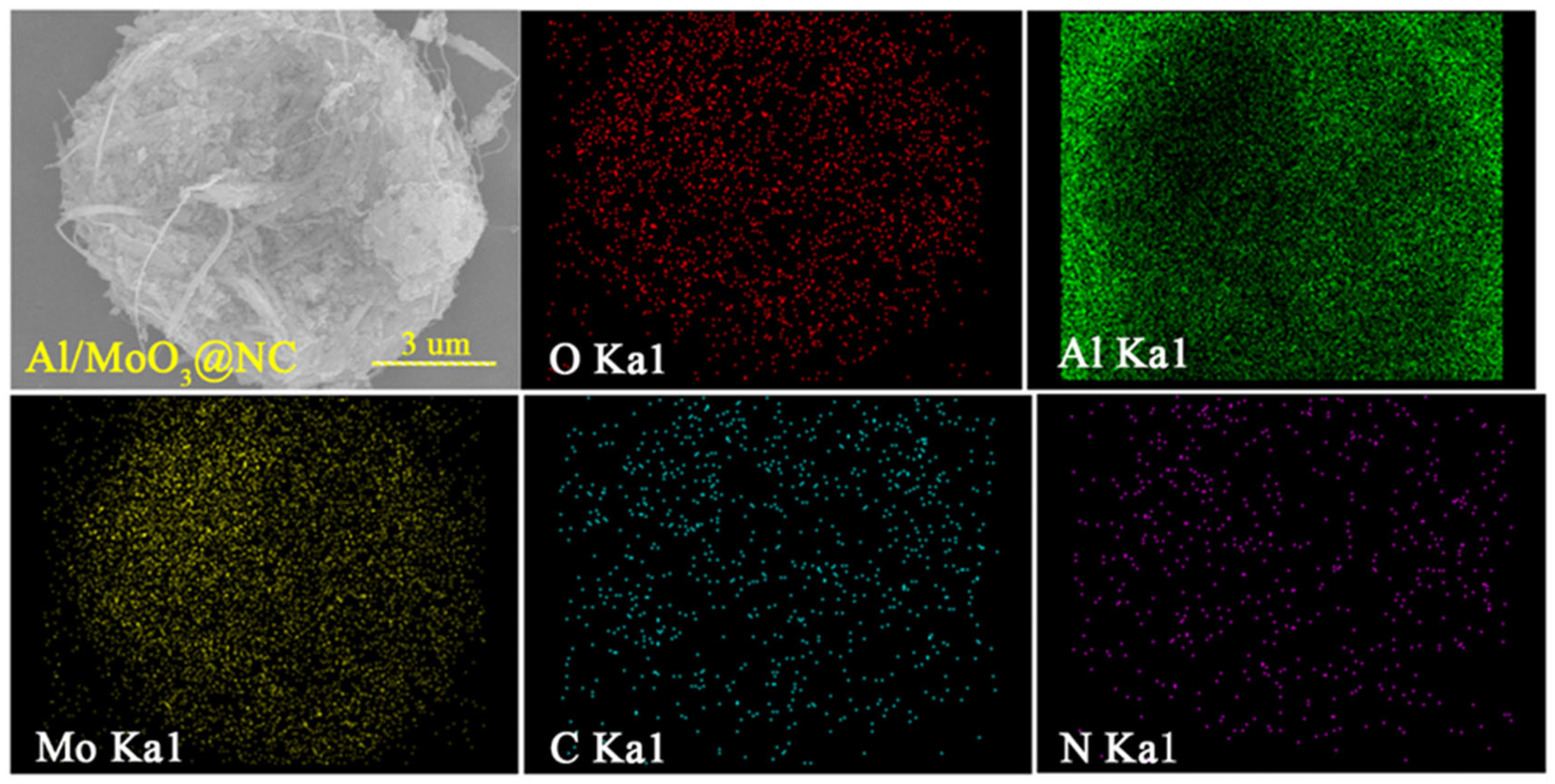
3.1. Micromorphology and Composition Characterization

The morphologies of the samples are shown in Figure 3. Figure 3a,c shows the morphology of Al nanoparticles and their corresponding size distribution, respectively. The size of Al nanoparticles ranged from 25 nm to 150 nm. Figure 3b,d displays the morphology and width distribution of MoO3 nanostrips, which ranged from 75 nm to 200 nm. The morphology of the mechanically mixed composite Al/MoO3 is shown in Figure 3e. As seen, the Al nanoparticles were uniformly distributed on the MoO3 nanostrips, but the contact was rather loose compared with the electrospray counterparts (Figure 3g). With the help of NC, Al and MoO3 could be bound into an intact structure resembling a bird nest, as shown in Figure 3g. And the size of the composite particle was around 12 μm. From the enlarged image of Figure 3h, it is evident that NC filled the hollow part between Al and MoO3, and more importantly, it served as the network to bond them together. Additionally, the FTIR spectra in Figure 3f indicate that they were merely a physical combination since no new bonds were generated during the electrospray process. To characterize the distribution of each component, the typical element Mo, Al and N, O, C of the components MoO3, Al and NC were scanned and mapped throughout the composite particle, and the typical results are shown in the Figure 4. From the elemental mapping results, we could learn that each component uniformly dispersed all over the composite particle. Furthermore, the NC binder homogeneously dispersed between oxidant and fuel, which will benefit the heat accumulation and the transfer of heat and mass during the thermite reaction.

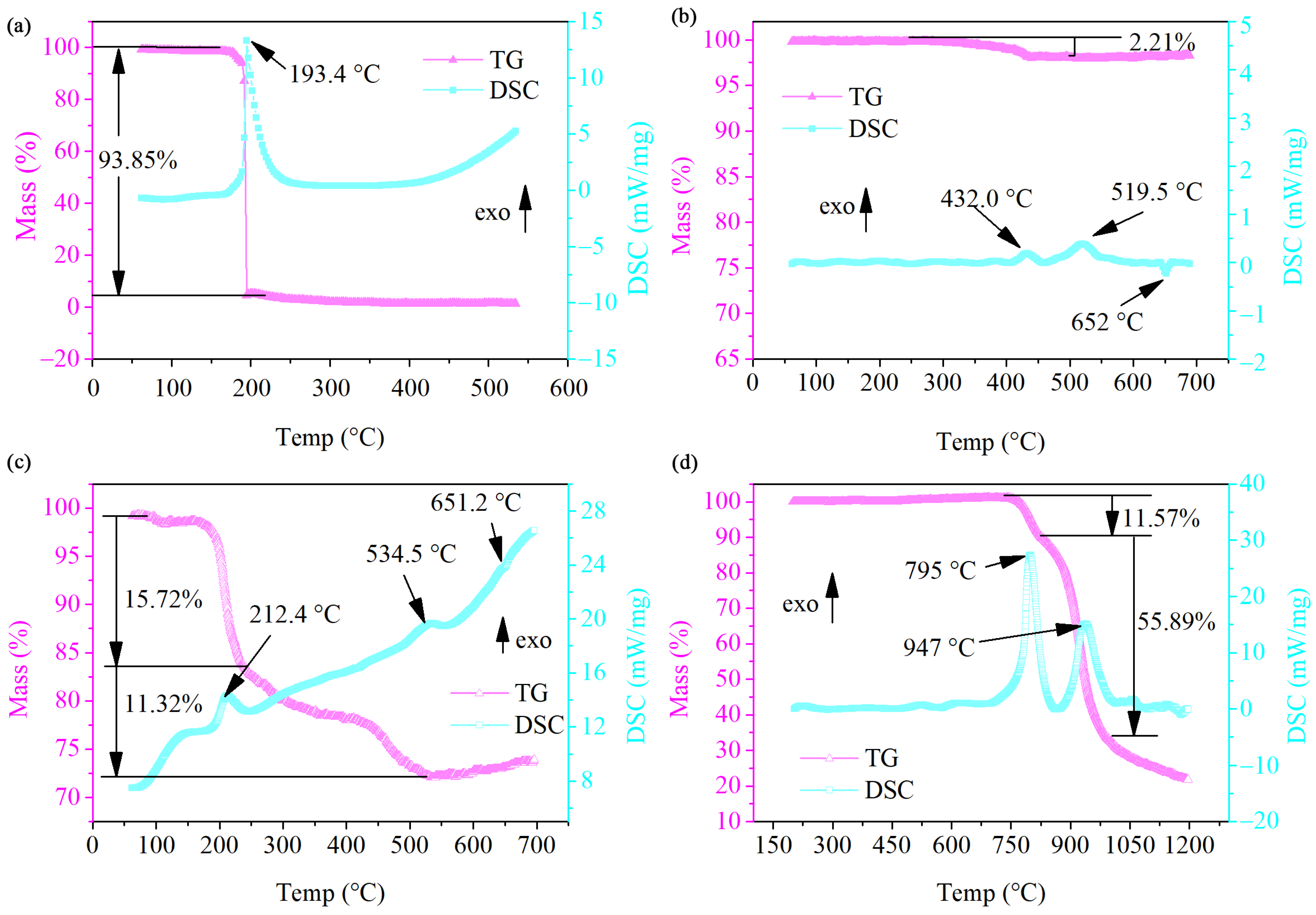
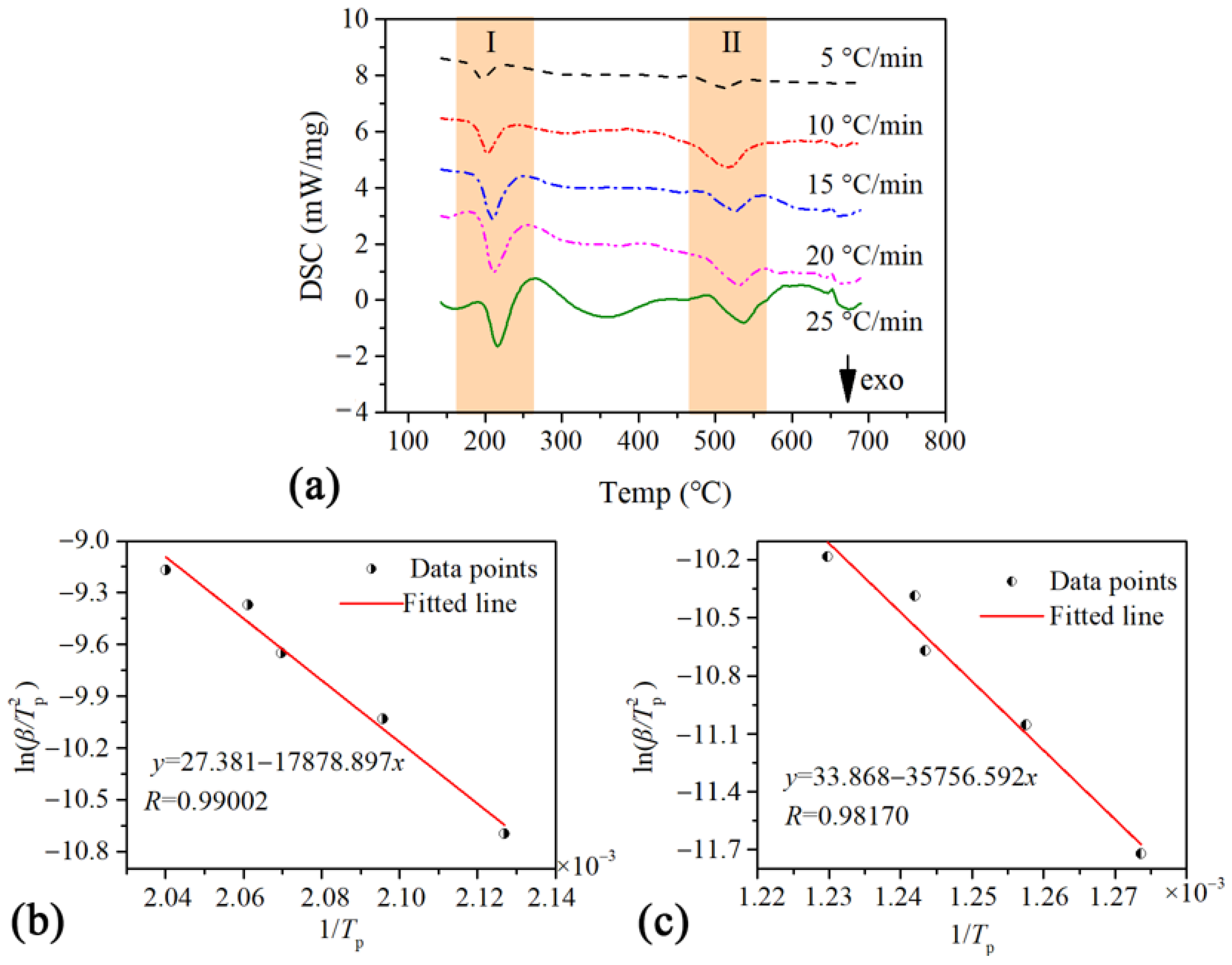
3.2. Thermodynamic Behavior Characterization

To study the thermal behavior of Al/MoO3-E, the DSC-TGA instrument was used in this work to characterize the thermal reaction of Al/MoO3-E within an argon atmosphere. The DSC thermographs of NC, Al/MoO3-M, Al/MoO3-E and MoO3 within an argon atmosphere at the heating rate of 20 °C·min−1 are illustrated in Figure 5. There was only one fierce exothermic process initiated at ~150 °C for NC (Figure 5a), and its exothermic peak temperature was 193.4 °C. During this process, the weight went through a cliff-like drop with a loss of 93.85%. Regarding the Al/MoO3-M, the thermite reaction went through two exothermic processes starting from 400 °C and 460 °C, and the corresponding peak temperatures for them were 432.0 °C and 519.5 °C, respectively. After that, a small endothermic process with a peak temperature of 652 °C occurred, which was the melting process of extra Al particles. The melting point of MoO3 was 795 °C, and its decomposition process began at a temperature larger than 650 °C (Figure 5d). Therefore, it could be concluded that the thermite reaction of Al nanoparticles and MoO3 nanostrips was in a solid–solid phase, of which the reaction rate greatly depended on the transport distance between the oxidant and fuel. With the help of NC, Al and MoO3 particles bonded into an integrated structure, which changed the original mass and heat transfer routes for both NC and Al/MoO3. As shown in Figure 5c, the temperature of the exothermic peak of NC returned to 212.4 °C, 19 °C higher than that of pure NC. More surprisingly, there was only one prominent exothermic peak for Al/MoO3-E instead of the original two peaks for the thermite reaction. Additionally, the peak temperature was postponed to 534.5 °C which was 15 °C higher than the original peak temperature of the neat thermite reaction. It indicated that the heat accumulation pattern of NC in Al/MoO3-E was not as concentrated as pure NC. Along with the imported heat from the equipment, the heat generated from the decomposition would spread fast among the three components. Therefore, the decomposition rate of NC decreased with a weaker heat accumulation, which led to a delay in the fierce exothermic process. On the contrary, the heat release of the Al/MoO3-E thermite reaction became more focused than Al/MoO3-M, for which the two exothermic peaks of the latter became one exothermic process of the former. This proved the high transport efficiency of mass and heat between the oxidant and fuel due to their tight contact.
To further elucidate the thermodynamic mechanism of Al/MoO3-E, DSC-TG measurements at five heating rates within an argon atmosphere were conducted. The DSC curves at five heating rates are displayed in Figure 6a, and the peak temperatures of the DSC curves under different heating rates are listed in Table 1. With those peak temperatures, the activation energy of each reaction stage could be calculated based on the Kissinger method. According to the Kissinger Equation (1), ln β T p 2 is linearly correlated to 1 T p with a slope of E a R and an intercept of ln R A E a [38]. Therefore, the activation energy Ea and frequency factor A could be acquired by linearly fitting a ln β T p 2 vs. 1 T p relationship based on the data points from the DSC curves.
ln β T p 2 = ln R A E a E a R 1 T p
In the equation, β is the heating rate, K·min−1; Tp is the peak temperature of the exothermic peak in the DSC curve, K; R is the universal gas constant, 8.314 J·mol−1·K−1; A is pre-exponential factor, s−1; and Ea is the activation energy, kJ·mol−1.
The linear fitting plots of the two exothermic processes are shown in Figure 6b,c, respectively. For both fittings, the correlation coefficients were higher than 0.98. The intercept and slope for the two fitting lines were 27.381 and −17,878.897, 33.868 and −35,756.592, respectively. Hence the activation energy for the first and second exothermic peaks should be 148.654 kJ·mol−1 and 297.280 kJ·mol−1, respectively. The activation energy was comparable to that of the electrosprayed Al/PVDF/MoO3 in work [39], in which both Al and MoO3 were the shape of a sphere less than 100 nm. It indicated that the boost effect of NC was more efficient than PVDF. And the corresponding lg(A) for them was 14.3657 and 17.4839, respectively. Furthermore, the kinetic equations of the two exothermic processes were acquired by analyzing the TG data. The Coats–Redfern integral method was applied to investigate the activation energy and pre-exponential factor from mass loss data using 41 major reaction mechanisms; the fitting results are shown in Table 2.
For exothermic peak I, the reaction mechanism was conformed to the Avrami–Erofeev equation of n = 4, and the exothermic process was controlled by nucleation and the growth rate [40]. The integral formula was G ( α ) = [ ln ( 1 α ) ] 4 , and the corresponding differential form was f ( α ) = 4 1 α [ ln ( 1 α ) ] 3 , in which α was the conversion degree of the reactant. For this case, due to the intense connection of NC and the solid phase of Al/MoO3, the decomposition of NC relied on the solid particles due to the intense connection between the NC and the solid phase of Al/MoO3. Under such conditions, the reaction of NC started and concentrated on the surface of the solid phases. And the decomposition of NC could keep going on with continuous accumulation of heat and mass. The reaction rate of NC relied on the nucleation and growth rate on the surface of the solid phase. Therefore, the most probable mechanism function was a differential equation f(α). By substituting the Ea and A into the equation d α d t = A f ( α ) e E R T , the kinetic equation could be acquired as in d α d t = 10 14.3657 × 4 1 α [ ln ( 1 α ) ] 3 × e 17.879 T . In the case of exothermic process II, the reaction mechanism was in accordance with the Zhuravlev–Lesokhin–Tempelman (Z-L-T) equation, and the exothermic reaction was controlled by a three-dimensional diffusion rate [41]. The integral formula was G ( α ) = [ ( 1 α ) 1 / 3 1 ] 2 and the corresponding differential form was f ( α ) = 2 3 [ ( 1 α ) 1 / 3 1 ] 2 . For the stage, although the thermite reaction and the oxidation of NC residue both occurred, the former reaction was dominant. Additionally, the reaction rate at this stage relied on the diffusion rate of the solid oxidant (MoO3) and oxidizing gases from NC. The kinetic equation could be acquired as in d α d t = 10 17.4839 × 2 3 [ ( 1 α ) 1 / 3 1 ] × e 35.757 T .

3.3. Sensitivity Tests

To test the applicable feasibility of a certain sample, one of the most important tests is the sensitivity test. For energetic materials, the impact sensitivity and flame sensitivity are two kinds of common tests to evaluate the safety of the materials for engineering application. The impact and flame sensitivities of Al/MoO3-E and Al/MoO3-M are listed in Table 3. The ignition height of the impact sensitivity was acquired by the up-and-down method, until the reaction probability of the sample reached 50%. And the larger the ignition height, the lower the impact sensitivity will be. As shown in Table 3, the ignition height for Al/MoO3-E was 23 cm, which was 8 cm shorter than that for Al/MoO3-M. It indicated the Al/MoO3-M was less sensitive to the impact stimulus than the electrosprayed one. On the contrary, in the case of flame sensitivity, the ignition distance of the former sample was 50 cm, which was 8 cm larger than the latter sample. It proved that the mechanically mixed sample was more sensitive to the flame stimulus than the electrosprayed sample. It indicated that Al/MoO3-E was more suitable for the application of mechanically initiated devices such as primer or percussion caps.

3.4. Combustion Performances

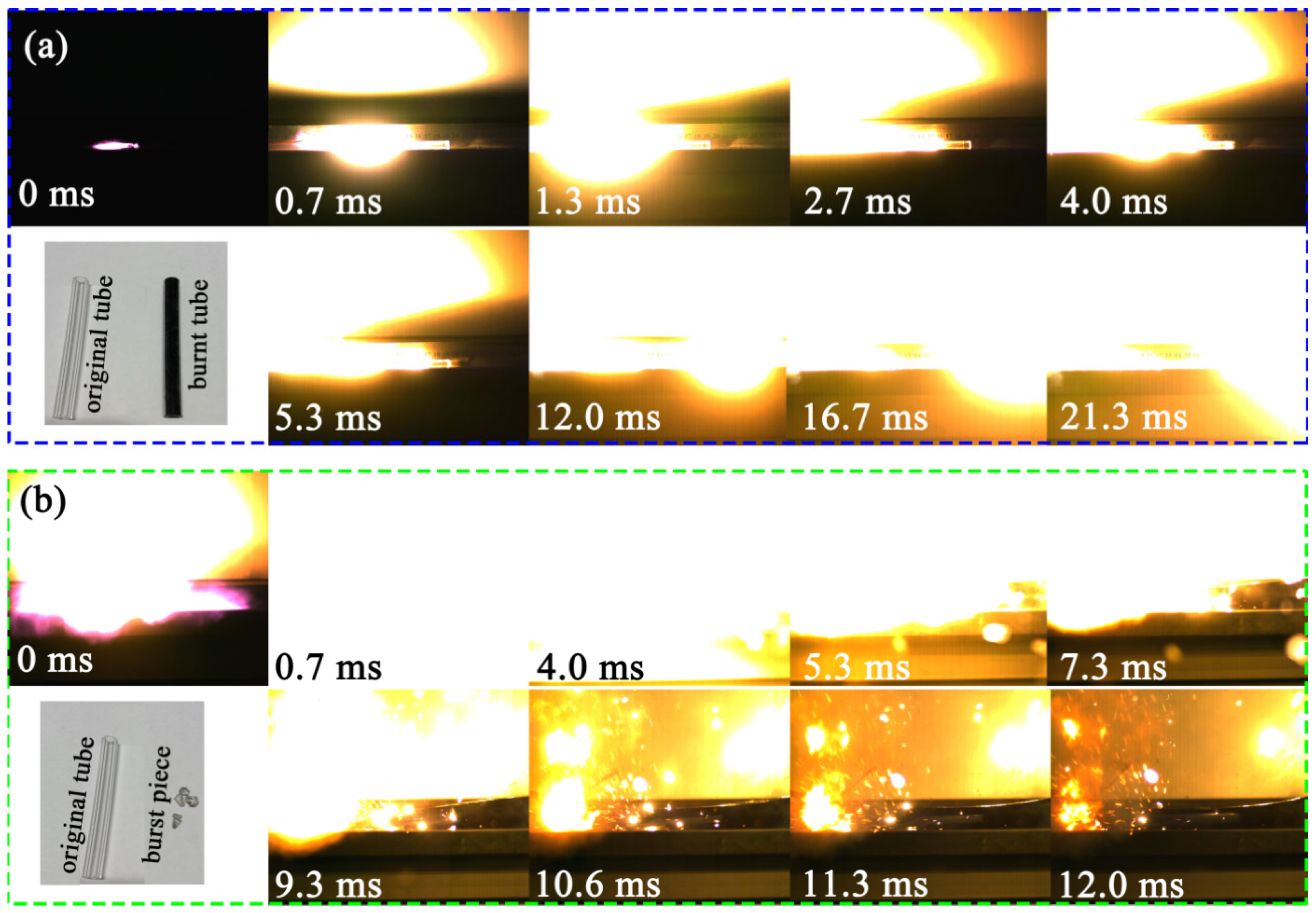
3.4.1. Constant Volume Combustion Test

The energy output potential of an energetic material is usually evaluated by the energy release rate and gross energy output. And the corresponding characteristic will be a key criterion for the further application of an energetic material. The constant volume combustion test is a measurement of combustion performance in a constant-volume vessel, which is a good way to analyze the energy release rate and gross energy output. Under this condition, the reaction energy is immediately released within a very short time in a confined space. In a typical test, the pressure change along the combustion process is recorded. Therefore, the pressurizing rate and the area below the curve separately indicates the reaction rate and the total work capacity. In this work, the test was conducted under atmospheric pressure and results are listed in Table 4. The maximum pressure of Al/MoO3-E was 1.96 MPa, which was 0.69 MPa higher than that of the mechanically mixed counterpart. And typical P–t curves and the mean maximum pressures for the samples are displayed in Figure 7. Figure 7 indicates that the pressurization rate and the maximum pressure of Al/MoO3-E are higher than those of the Al/MoO3-M. This proves the fact that reaction rate of Al/MoO3-E particles is larger than that of Al/MoO3-M particles due to a much more intimate connection. Furthermore, the area below the curve of Al/MoO3-E, which corresponded to the pressure–time integral, was evidently much bigger than that of Al/MoO3-M, indicating a better work capacity of Al/MoO3-E particles.

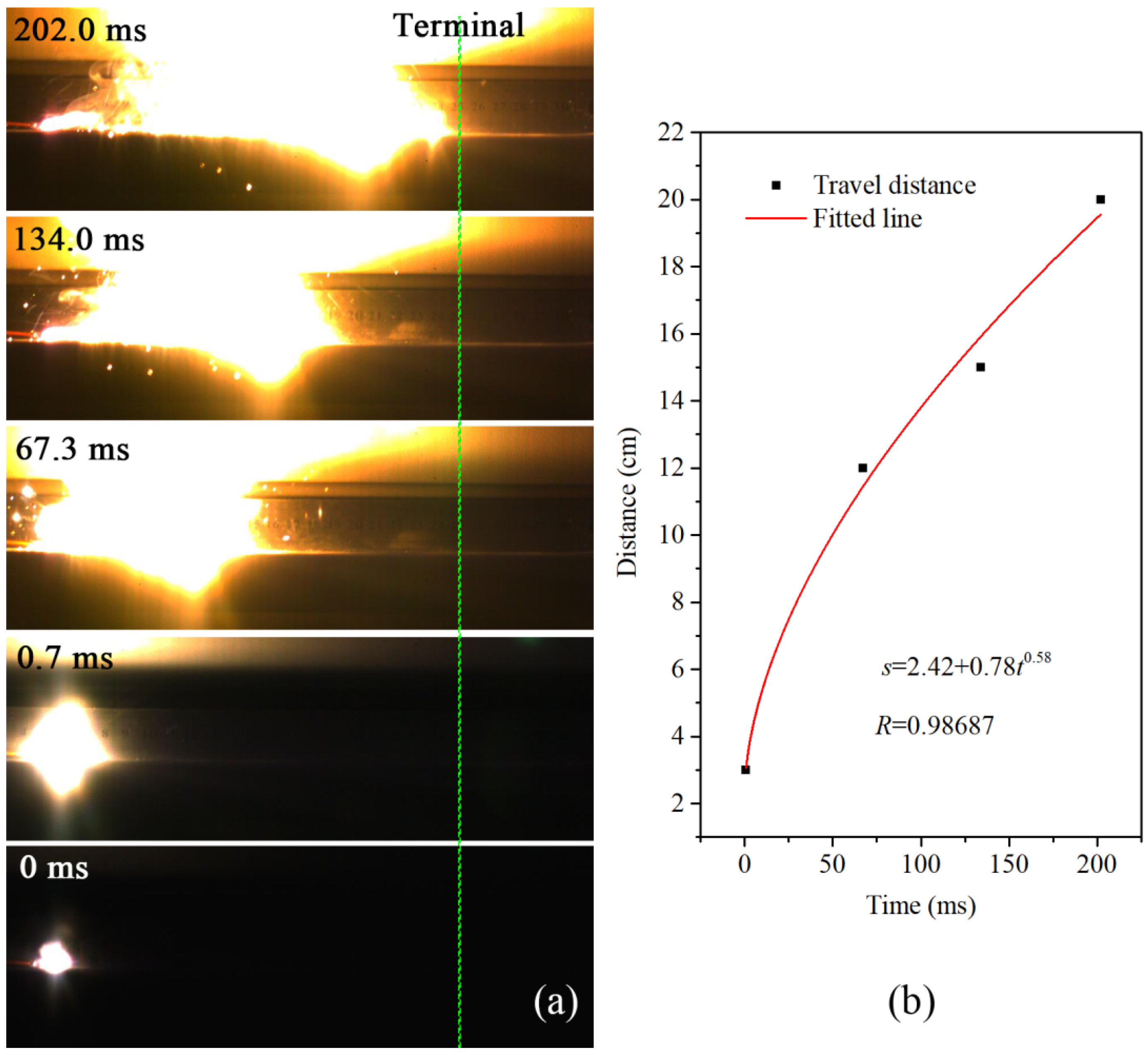
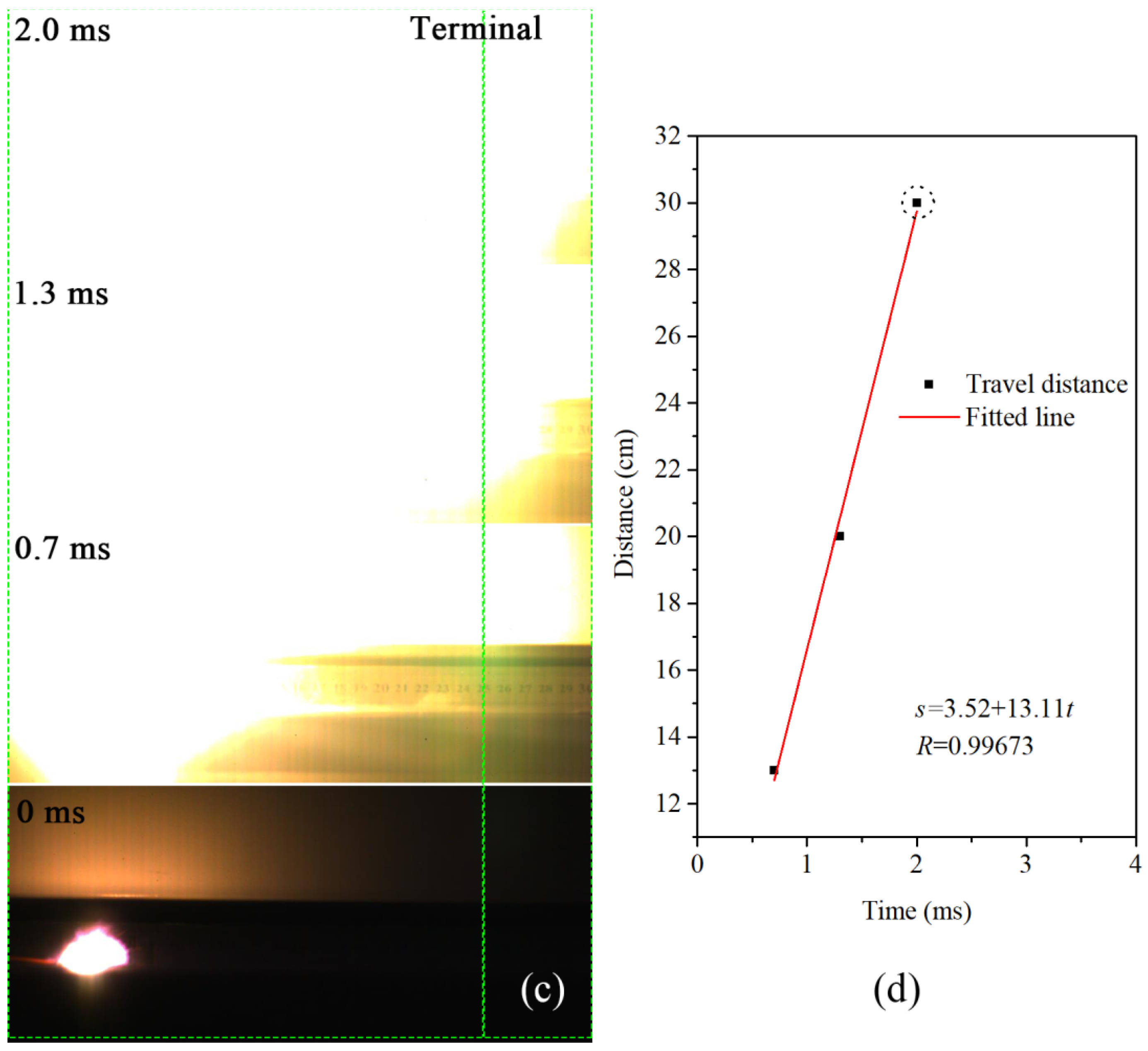
3.4.2. Combustion Performance and Velocity Test

The combustion performance of Al/MoO3-E particles was characterized under confined and unconfined conditions, respectively. For comparison, the combustion performance of Al/MoO3-M particles were also conducted under the same conditions. The combustion results under confined and unconfined conditions are displayed in Figure 8 and Figure 9, respectively. For all tests, the combustion sequences were relative to the ignition time; therefore, the moment of ignition was set to 0 ms. In the case of combustion under confined conditions (samples inside the PMMA tube), the situations of the two samples were completely different from each other. For Al/MoO3-M particles, it took 12.0 ms to finish the combustion throughout the tube (Figure 8a). And compared with the original PMMA tube, the tube that went through combustion remained intact but was burned to black. On the contrary, in the case of Al/MoO3-E, the fierce combustion immediately started after ignition. It took merely 0.7 ms for the combustion of Al/MoO3-E particles to be completed throughout the tube (Figure 8b). At that time, the shooting area was suddenly filled with bright light. After the fade of the combustion light, it could be identified that the tube burst into pieces and the ruler next to the tube also fell down. Moreover, there were sparks in the surrounding area from 10.6 ms to 12.0 ms, which indicated the burst reaction of Al/MoO3-E. The inserted photo in Figure 8b displays the tube pieces shattered by the fierce combustion.
It could be concluded from the combustion phenomena that the combustion rate of electrosprayed Al/MoO3-E was much higher than that of the mechanically mixed counterpart. With such a high combustion rate, a large amount of released heat accumulated in a very short time, which led to the burst of the PMMA tube. In comparison, the combustion of Al/MoO3-M was much gentler, indicating a slower reaction rate. The addition of NC not only bonded Al and MoO3 particles together, but also provided a heat and mass transfer path for the system.
To avoid the fierce burst phenomenon, the combustion velocities of the samples were measured in open air. For each test, 0.2 g of the sample was loosely placed on the surface of a flat slab in the shape of 20 cm × 5 cm × 0.5 cm. The sample was ignited by an electric igniter. The corresponding combustion results are shown in Figure 9. Figure 9a,c are the combustion photos of the samples, and their corresponding travel history curves are shown in Figure 9b,d, respectively. From Figure 9b, it could be seen that the travel distance of Al/MoO3-M increased exponentially with time, and it took 200 ms to complete the travel path. On the other hand, in the case of the electrosprayed counterpart, the travel distance linearly increased with time at a slope of 13.11, and it took less than 2 ms to finish traveling. Even under such unconfined condition, the combustion velocity of the electrosprayed sample was way ahead of the physically mixed sample. It could be inferred that it was the integrity of the structure rather than the confinement that influenced the reaction rate. With the addition of confinement, the combustion of the electrosprayed sample could turn into deflagration due to the rapid heat accumulation.

4. Conclusions

This work presents the reaction performance of Al/MoO3 nanothermite prepared by the electrospray strategy with Al nanoparticles and MoO3 nanostrips. We compared it with the physically mixed counterpart. The morphology of the electrosprayed Al/MoO3 nanothermite particles resembled a bird nest, showing good integrity compared to the loose physical mixture. DSC-TG thermal analyses showed that there were two main exothermic processes for electrosprayed Al/MoO3 particles. The Kissinger method and Coats–Redfern integral method were applied to estimate the activation energy and the thermodynamic reaction mechanism, respectively. Furthermore, the pressurization behavior was measured. Both the maximum pressure and the pressurization rate of the electrosprayed sample were higher than those of the mechanically mixed one. Moreover, the electrosprayed sample was more sensitive to flame and impact stimuli than the mechanically mixed one, which will benefit its application in primer or percussion caps. In addition, the combustion performance of the sample was evaluated. Under confined conditions, the reaction rate of the electrosprayed sample was so fast that fierce deflagration was achieved. On the contrary, the mean combustion rate of the mechanically mixed sample was much slower and gentler. Even under unconfined conditions, the mean combustion velocity of the electrosprayed sample was a hundred times as fast as that of the mechanically mixed sample. In conclusion, the electrospray integration of Al/MoO3 nanothermite will be a good strategy to acquire both a high reaction rate and moderate sensitivity. And the resulting products will be superior candidates for green primer and civil excavation applications.

Author Contributions

Conceptualization, methodology, validation, formal analysis, investigation, writing—original draft preparation, resources, Y.L; data curation, writing—review and editing, visualization, H.R. and Q.X.; funding acquisition, Y.L. and Q.X. All authors have read and agreed to the published version of the manuscript.

Funding

This work was supported by the Excellent Discipline Cultivation Project by JHUN (grant no. 2023XKZ042), and the Doctoral Research Start-up Fund Project (grant no. PBSKL-2022-QD-03).

Institutional Review Board Statement

Not applicable.

Informed Consent Statement

Not applicable.

Data Availability Statement

The datasets used and/or analyzed during the current study are available from the corresponding author on reasonable request.

Conflicts of Interest

The authors declare no conflicts of interest.

References

  1. de Souza, K.M.; de Lemos, M.J.; Ribeiro, R.D.R.; Marin, A.M.G. Advanced isoconversional kinetic analysis of Fe2O3-2Al thermite reaction for plug and abandonment of oil wells. Chem. Eng. J. 2023, 455, 140725. [Google Scholar] [CrossRef]
  2. Junghare, S.; Kumari, S.; Chaudhary, A.; Kumar, R.; Rayalu, S. Thermite reaction driven pyrotechnic formulation with promising functional performance and reduced emissions. J. Hazard. Mater. 2022, 424, 127345. [Google Scholar] [CrossRef] [PubMed]
  3. Elbasuney, S.; Yehia, M.; Hamed, A.; Mokhtar, M.; Gobara, M.; Saleh, A.; Elsaka, E.; El-Sayyad, G.S. Synergistic catalytic effect of thermite nanoparticles on HMX thermal decomposition. J. Inorg. Organomet. Polym. Mater. 2021, 31, 2293–2305. [Google Scholar] [CrossRef]
  4. Josefson, B.L.; Bisschop, R.; Messaadi, M.; Hantusch, J. Residual stresses in thermite welded rails: Significance of additional forging. Weld. World 2020, 64, 1195–1212. [Google Scholar] [CrossRef]
  5. Elbasuney, S.; El-Sayyad, G.S.; Ismael, S.; Yehia, M. Colloid thermite nanostructure: A novel high energy density material for enhanced explosive performance. J. Inorg. Organomet. Polym. Mater. 2021, 31, 559–565. [Google Scholar] [CrossRef]
  6. Oh, S.; Park, S.; Min, G.; Park, H.; Yoo, Y.; Cho, S. Deflagration characteristics of thermite reaction mixtures under decoupled charges. Sci. Technol. Energ. Mater. 2020, 81, 114–120. [Google Scholar]
  7. Jian, G.; Chowdhury, S.; Sullivan, K.; Zachariah, M.R. Nanothermite reactions: Is gas phase oxygen generation from the oxygen carrier an essential prerequisite to ignition? Combust. Flame 2013, 160, 432–437. [Google Scholar] [CrossRef]
  8. Williams, A.; Shancita, I.; Altman, I.; Tamura, N.; Pantoya, M.L. On the Pressure Generated by Thermite Reactions Using Stress-Altered Aluminum Particles. Propellants Explos. Pyrotech. 2021, 46, 99–106. [Google Scholar] [CrossRef]
  9. Chen, J.; Guo, T.; Ding, W.; Song, J.; Yao, M.; Bei, F.; Li, S. Effect of CuO on the thermal kinetics and combustion properties of Al/MoO3 thermite prepared by ball milling. Ceram. Int. 2021, 47, 16500–16510. [Google Scholar] [CrossRef]
  10. Wu, J.; Feng, B.; Gao, Z.; Li, Y.; Wu, S.; Yin, Q.; Huang, J.; Ren, X. Investigation on the thermal decomposition and thermal reaction process of PTFE/Al/MoO3 fluorine-containing thermite. J. Fluor. Chem. 2021, 241, 109676. [Google Scholar] [CrossRef]
  11. Liu, J.W.; Li, S.; Li, M.; Zhou, Y.; Guo, T.; Han, Z.X.; Jiang, L. Thermal Analysis and Pyrolytic Behavior of Bimetal and Double Oxidant Thermite Al/Mg/MoO3/CuO. Propellants Explos. Pyrotech. 2023, 48, e202200290. [Google Scholar] [CrossRef]
  12. Rehwoldt, M.C.; Wang, H.; Kline, D.J.; Wu, T.; Eckman, N.; Wang, P.; Agrawal, N.R.; Zachariah, M.R. Ignition and combustion analysis of direct write fabricated aluminum/metal oxide/PVDF films. Combust. Flame 2020, 211, 260–269. [Google Scholar] [CrossRef]
  13. Wang, H.; Kline, D.J.; Biswas, P.; Zachariah, M.R. Connecting agglomeration and burn rate in a thermite reaction: Role of oxidizer morphology. Combust. Flame 2021, 231, 111492. [Google Scholar] [CrossRef]
  14. Xu, F.; Biswas, P.; Nava, G.; Schwan, J.; Kline, D.J.; Rehwoldt, M.C.; Mangolini, L.; Zachariah, M.R. Tuning the reactivity and energy release rate of I2O5 based ternary thermite systems. Combust. Flame 2021, 228, 210–217. [Google Scholar] [CrossRef]
  15. Shen, L.; Li, Y.; Zhang, L.; Zhu, S.; Yi, Z.; Zhu, C. Tuning the reactivity and energy release efficiency in aluminum alloy thermite by eutectic silicon. Chem. Eng. J. 2023, 466, 143113. [Google Scholar] [CrossRef]
  16. Wang, Y.; Liu, R.; Wan, Y. Thermal reaction properties of aluminum/iron fluoride nanothermites. J. Therm. Anal. Calorim. 2023, 148, 5297–5308. [Google Scholar] [CrossRef]
  17. Li, M.; Han, Z.; Jiang, L.; Xu, G. Study on combustion characteristics and pyrotechnic cutting effects of bimetal thermite Ni/Al/Fe2O3 system. Propellants Explos. Pyrotech. 2024, 49, e202300285. [Google Scholar] [CrossRef]
  18. Polis, M.; Stolarczyk, A.; Glosz, K.; Jarosz, T. Quo Vadis, Nanothermite? A review of recent progress. Materials 2022, 15, 3215. [Google Scholar] [CrossRef]
  19. Piercey, D.G.; Klapoetke, T.M. Nanoscale aluminum-metal oxide (thermite) reactions for application in energetic materials. Cent. Eur. J. Energ. Mater. 2010, 7, 115–129. [Google Scholar]
  20. Song, J.; Guo, T.; Ding, W.; Yao, M.; Bei, F.; Zhang, X.; Huang, J.; Fang, X. Study on thermal behavior and kinetics of Al/MnO2 poly (vinylidene fluorine) energetic nanocomposite assembled by electrospray. RSC Adv. 2019, 9, 25266–25273. [Google Scholar] [CrossRef] [PubMed]
  21. Wang, Y.T.; Zhang, X.T.; Xu, J.B.; Shen, Y.; Wang, C.A.; Li, F.W.; Zhang, Z.H.; Chen, J.; Ye, Y.H.; Shen, R.Q. Fabrication and characterization of Al–CuO nanocomposites prepared by sol-gel method. Def. Technol. 2021, 17, 1307–1312. [Google Scholar] [CrossRef]
  22. Ghedjatti, I.; Yuan, S.; Wang, H. Hot Bridge-Wire Ignition of Nanocomposite Aluminum Thermite Synthesized Using Sol-Gel-Derived Aerogel with Tailored Properties for Enhanced Reactivity and Reduced Sensitivity. Energies 2024, 17, 2437. [Google Scholar] [CrossRef]
  23. Zhou, J.; Pan, Q.; Guo, X.; Nie, J.; Liu, R. Preparation of microstructure controllable Al/WO3/F2603 MICs by droplet microfluidic technology to improve combustion performance. Chem. Eng. J. 2023, 477, 146419. [Google Scholar] [CrossRef]
  24. Wang, H.; Zachariah, M.R. Engineering Particle Agglomerate and Flame Propagation in 3D-printed Al/CuO Nanocomposites. Nano Micro-Scale Energ. Mater. Propellants Explos. 2023, 1, 253–284. [Google Scholar]
  25. Wang, H.; Jian, G.; Egan, G.C.; Zachariah, M.R. Assembly and reactive properties of Al/CuO based nanothermite microparticles. Combust. Flame 2014, 161, 2203–2208. [Google Scholar] [CrossRef]
  26. Nie, H.; Tan, L.P.; Pisharath, S.; Hng, H.H. Nanothermite composites with a novel cast curable fluoropolymer. Chem. Eng. J. 2021, 414, 128786. [Google Scholar] [CrossRef]
  27. Jiang, Y.; Wang, Y.; Baek, J.; Wang, H.; Gottfried, J.L.; Wu, C.-C.; Shi, X.; Zachariah, M.R.; Zheng, X. Ignition and combustion of Perfluoroalkyl-functionalized aluminum nanoparticles and nanothermite. Combust. Flame 2022, 242, 112170. [Google Scholar] [CrossRef]
  28. Zhang, Z.; Jiang, D.; Yang, L.; Song, W.; Wang, R.; Huang, Q. Preparation of RDX/F2311/Fe2O3/Al Composite Hollow Microspheres by Electrospray and Synergistic Energy Release during Combustion between Components. Materials 2024, 17, 1623. [Google Scholar] [CrossRef] [PubMed]
  29. Li, X.; Zachariah, M.R. Direct deposit of fiber reinforced energetic nanocomposites. Propellants Explos. Pyrotech. 2017, 42, 1079–1084. [Google Scholar] [CrossRef]
  30. Xiao, L.; Zhao, L.; Ke, X.; Zhang, T.; Hao, G.; Hu, Y.; Zhang, G.; Guo, H.; Jiang, W. Energetic metastable Al/CuO/PVDF/RDX microspheres with enhanced combustion performance. Chem. Eng. Sci. 2021, 231, 116302. [Google Scholar] [CrossRef]
  31. Wang, S.J.; Wang, D.; Chen, P.; Yan, S.; Jiao, Q.J.; Guo, X.Y. Preparation and characterization of Al@TKX-50@NC composite microspheres by electrospray. Mater. Chem. Phys. 2023, 305, 127910. [Google Scholar] [CrossRef]
  32. Feng, C.; Ye, B.; Ma, Y.; Cheng, W.; Shi, S.; Zhao, F.; An, C.; Wang, J. Electrospray fabrication of CL-20 composite microspheres for high-energy EFIs: Microstructure modulation and performance optimization. Powder Technol. 2024, 437, 119563. [Google Scholar] [CrossRef]
  33. Niu, H.-T.; Zhang, Y.; Xiao, G.; He, X.-H.; Yao, Y.-G. Preparation of quasi-isotropic thermal conductive composites by interconnecting spherical alumina and 2D boron nitride flakes. Rare Met. 2023, 42, 1283–1293. [Google Scholar] [CrossRef]
  34. Wu, N.; Che, S.; Sun, L.; Liu, H.; Li, Z.; Sun, Y.; Qian, J.; Yang, W.; Li, Y. Dual Network Structures of Polyurethane/Boron Nitride Nanosheets/Alumina for Improved Thermal Management of Polymers. ACS Appl. Nano Mater. 2023, 6, 17196–17205. [Google Scholar] [CrossRef]
  35. Jacob, R.J.; Ortiz-Montalvo, D.L.; Overdeep, K.R.; Weihs, T.P.; Zachariah, M.R. Incomplete reactions in nanothermite composites. J. Appl. Phys. 2017, 121, 054307. [Google Scholar] [CrossRef] [PubMed]
  36. Xu, W.; An, C.; Wang, J.; Dong, J.; Geng, X. Preparation and properties of an insensitive booster explosive based on LLM-105. Propellants Explos. Pyrotech. 2013, 38, 136–141. [Google Scholar] [CrossRef]
  37. Xu, R.; Yan, Z.; Yang, L.; Wang, Q.; Tong, W.; Song, N.; Han, J.-M.; Zhao, Y. Nanoscale homogeneous energetic copper azides@porous carbon hybrid with reduced sensitivity and high ignition ability. ACS Appl. Mater. Interfaces 2018, 10, 22545–22551. [Google Scholar] [CrossRef] [PubMed]
  38. Kissinger, H.E. Reaction kinetics in differential thermal analysis. Anal. Chem. 1957, 29, 1702–1706. [Google Scholar] [CrossRef]
  39. Chen, J.; Guo, T.; Yao, M.; Song, J.; Ding, W.; Mao, Y.; Li, S.; Zhu, R. Thermal behavior and combustion performance of Al/MoO3 nanothermites with addition of poly (vinylidene fluorine) using electrospraying. Mater. Res. Express 2020, 7, 115009. [Google Scholar] [CrossRef]
  40. De Bruijn, T.; De Jong, W.; Van Den Berg, P. Kinetic parameters in Avrami—Erofeev type reactions from isothermal and non-isothermal experiments. Thermochim. Acta 1981, 45, 315–325. [Google Scholar] [CrossRef]
  41. Huang, J.; Jiang, J.; Ni, L.; Zhang, W.; Shen, S.; Zou, M. Thermal decomposition analysis of 2,2-di-(tert-butylperoxy)butane in non-isothermal condition by DSC and GC/MS. Thermochim. Acta 2019, 673, 68–77. [Google Scholar] [CrossRef]
Figure 1. Diagram of the electrospray fabrication of Al/MoO3 nanothermite.
Applsci 14 05522 g001
Figure 2. Diagrams of impact sensitivity (a) and flame sensitivity (b) test equipment.
Applsci 14 05522 g002
Figure 3. (a,b) SEM images of Al nanoparticles and MoO3 nanostrips, respectively; (c,d) size distribution of (a,b), respectively; (e) SEM image of mechanically mixed Al/MoO3-M; (f) FTIR spectra of NC and the electrosprayed Al/MoO3; (g,h) SEM images of Al/MoO3-E.
Applsci 14 05522 g003
Figure 4. Elemental mappings of O, Al, Mo, C and N in Al/MoO3-E.
Applsci 14 05522 g004
Figure 5. Thermal DSC and TG curves of the samples at a heating rate of 20 °C·min−1 within an argon atmosphere: (a) NC; (b) Al/MoO3-M; (c) Al/MoO3-E; (d) MoO3 nanostrips (in each figure, “exo” is short for “exothermic”, and the upward vertical arrow alongside “exo” indicates that the upward peaks in DSC curves are the exothermic peaks).
Applsci 14 05522 g005
Figure 6. DSC thermographs of Al/MoO3-E at five heating rates (a) and the corresponding linear fitting diagram of the peak temperature points: (b) exothermic peak I and (c) exothermic peak II of Al/MoO3-E.
Applsci 14 05522 g006
Figure 7. Typical Pt curves of Al/MoO3-E and Al/MoO3-M (insert: comparison of the mean maximum pressure for each sample).
Applsci 14 05522 g007
Figure 8. Combustion performance of (a) Al/MoO3-M and (b) Al/MoO3-E under confined conditions ((a,b) are the comparison of the tube conditions before and after the combustion of Al/MoO3-M and Al/MoO3-E, respectively).
Applsci 14 05522 g008
Figure 9. Combustion history of (a) Al/MoO3-M and (c) Al/MoO3-E in an open environment, and their corresponding travel distance vs. time relations: (b) Al/MoO3-M; (d) Al/MoO3-E. (The green dot lines in (a,c) indicate the ends of the samples.
Applsci 14 05522 g009aApplsci 14 05522 g009b
Table 1. Kinetic parameters of exothermic reactions of electrosprayed Al/MoO3 based on the Kissinger method.
Exothermic PeakPeak Temperatures (°C)Ea (kJ·mol−1)lg(A(s−1))R
5 °C·min−110 °C·min−115 °C·min−120 °C·min−125 °C·min−1
I197204210212217148.64514.36570.99002
II512522531532540297.28017.48390.98170
Table 2. The kinetic mechanisms and parameters of exothermic reactions of Al/MoO3-E.
Exothermic PeakHeating Rates (K·min−1)Ea (kJ·mol−1)lg(A(s−1))RThe Most Possible FunctionsKinetic Equation
I5115.209328.224890.993668 4 1 α [ ln ( 1 α ) ] 3 10 14.3657 × 4 1 α [ ln ( 1 α ) ] 3 × e 17.879 T
10122.767529.616360.995394
15131.194031.065990.991795
20124.275828.993060.981353
25106.270823.591660.965036
II5260.007924.863170.988413 2 3 [ ( 1 α ) 1 / 3 1 ] 2 10 17.4839 × 2 3 [ ( 1 α ) 1 / 3 1 ] × e 35.757 T
10189.945317.521240.980036
15237.943522.755620.986147
20305.766329.668580.976977
25294.653227.914230.985651
Table 3. The impact and flame sensitivities of Al/MoO3-M and Al/MoO3-E.
SampleImpact SensitivityFlame Sensitivity
H50/cmStandard Deviation/cmH50/cmStandard Deviation/cm
Al/MoO3-M351502
Al/MoO3-E231422
Table 4. The maximum pressure for each sample.
SampleWeight/gPmax/MPa P max /MPa σ/MPa
Al/MoO3-M0.0961.231.270.18
0.1021.16
0.0991.41
Al/MoO3-E0.1012.021.960.16
0.0951.83
0.0972.04
Disclaimer/Publisher’s Note: The statements, opinions and data contained in all publications are solely those of the individual author(s) and contributor(s) and not of MDPI and/or the editor(s). MDPI and/or the editor(s) disclaim responsibility for any injury to people or property resulting from any ideas, methods, instructions or products referred to in the content.

