Article

Study on the Two-Step Construction Method of Super Large Cross-Section Tunnels Crossing Karst Cave Areas

1
Research Institute of Highway Ministry of Transport, Beijing 100088, China
2
Rioh Traffic Safety Co., Ltd., Beijing 100088, China
3
College of Civil Engineering, Taiyuan University of Technology, Taiyuan 030024, China
*
Authors to whom correspondence should be addressed.
Appl. Sci. 2024, 14(11), 4500; https://doi.org/10.3390/app14114500
Submission received: 26 April 2024 / Revised: 22 May 2024 / Accepted: 22 May 2024 / Published: 24 May 2024
(This article belongs to the Special Issue Advances in Tunnel and Underground Construction)

Abstract

:
To explore the solution of the two-step method applied in the rapid construction of super large cross-section tunnels passing through IV-and V-grade surrounding rock sections in karst cave areas, based on an engineering example of the Lianhuashan Tunnel, we use the numerical calculation method to analyze the stability of surrounding rock and the design parameters of the control measures for super large cross-section tunnels during the construction of the step method. The calculated results show that the working face of IV-grade surrounding rock can be stabilized by an advanced small pipe, and the stability of the supporting structure should be controlled mainly by IV-grade surrounding rock. In order to control the stability of the tunnel face, it is necessary to use an advanced large pipe shed in the surrounding V-grade rock. The reinforcement range of the advanced large pipe shed is 120° and the length is 20 m. This is the most economical design parameter of the advanced large pipe shed, ensuring the deformation control effect. For control of the stability of the supporting structure, under the condition that the working space is suitable for large machinery, the settlement of the arch of the supporting structure can be obviously reduced by shortening the step cycle footage and reducing the step length, and the peripheral convergence of the supporting structure can be obviously reduced by reducing the step height. After comprehensive analysis and considering the development of karst caves, the advanced support measures, design parameters, bench excavation design parameters, initial support measures, karst cave treatment measures, and bench construction process of IV- and V-grade surrounding rock is determined. The application verification shows that the research results have a good control effect on the stability of the surrounding rock and cave and are suitable for large-scale mechanical operations, which can significantly improve the excavation speed of the super large cross-section tunnel passing through the IV- and V-grade surrounding rock sections in the karst cave area.

1. Introduction

The IV- and V-grade surrounding rock sections of super large cross-section tunnel construction mainly adopt the partial excavation method used in China. Three-step methods, single-side heading methods, CD methods, CRD methods, and double-sided heading methods are widely used. The support system formed by a small pilot tunnel and temporary support [1,2,3,4] has the problems of a narrow working space, complex process, and slow construction speed. When this support system is used in karst cave strata, because the influence of karst cave development on construction is not considered, there are a series of problems, such as difficulty in implementing karst cave treatment measures, difficulty escaping construction personnel during disasters, and inability to use large-scale construction machinery during disaster treatment.
The two-step method can provide a large construction space and is conducive to the use [5,6] of large-scale construction machinery due to the small number of blocks. However, under the condition of weak surrounding rock, there are also problems such as poor stability of the tunnel face and large deformation of the supporting structure. In the past, this method was mostly used in the II-grade and III-grade surrounding rock of the 3-lane tunnel. In recent years, with the development of large construction machinery and surrounding rock reinforcement technology, the micro-step method has been widely used in the IV-grade surrounding rock of 3-lane tunnels (the relevant provisions of the Technical Specifications for Construction of Highway Tunnels (JTG/T 3660-2020)) [7] and has been explored and applied in the V-grade surrounding rock of 3-lane tunnels. By means of numerical simulation, Song Shuguang [8] and Zou Chenglu [9] studied the effects of geometric parameters such as step length, height, and excavation footage on the deformation control ability of the surrounding rock and supporting structure under the geological conditions of the weakly broken surrounding rock. Wu Jingang [10], Li Wenjiang [11], Luo Yanbin [12], Zuo Yiming [13], and Yuan Xiaoshuai [14] studied the measures of advanced support, initial support, and locking anchor rods in step method construction. Some of the research results have been verified by engineering applications. This shows that the two-step method and reasonable engineering measures can improve the tunnel deformation control ability and reduce the risk of collapse and large deformation.
From the above analysis, the two-step method has advantages in terms of the stability of karst caves, karst cave treatment, and mechanized construction (construction speed). Based on this excavation method, targeted technical measures can be taken to solve the problems of construction speed, cost, and safety of super large cross-section tunnels crossing karst cave areas. However, at present, research on the stability of tunnel construction in karst cave areas has focused on analyzing the effect of karst caves on the stability of surrounding rock [15] and the deformation and stress of supporting structures via numerical calculations [16,17]. The research on the systematic theoretical analysis and construction technology system of the two-step method for the construction of super large cross-section tunnels passing through karst areas is insufficient. The Lianhuashan Tunnel in Liuzhou City is a 3-lane super large cross-section tunnel located in an area where karst caves are strongly developed. Many intrusions into karst caves are detected in the additional construction survey stage. Due to the construction period, the original designs of the double-sided heading method and CD method are optimized to the two-step method, but many disasters, such as collapse, large deformation, and karst cave inrush, have occurred during the construction process. Therefore, based on the Lianhuashan tunnel project, a numerical calculation method is used to analyze the deformation and failure characteristics of the two-step method for constructing a super large cross-section tunnel under the condition of weakly broken surrounding rock failure. A two-step construction technology system for a super large cross-section tunnel crossing a karst cave area is established and applied in a supporting project.

2. Overview of Related Supporting Projects

The Lianhuashan Tunnel is a two-way, 6-lane, separated highway tunnel located north of Liuzhou City, Guangxi Province. It is a neighborhood tunnel (the clear distance ranges from 15.12 m to 22.12 m). The drilling and blasting methods are adopted in the tunnel construction. The excavation section is more than 150 m2 and the length is approximately 1.87 km. The lithology of the tunnel site is mainly limestone and red clay. The surrounding rock grade is mainly IV and V, and the geological longitudinal section is shown in Figure 1. A supplementary survey of the left line mileage K2 + 920~K3 + 060 section and the right line mileage YK2 + 920~YK3 + 060 section of the Lianhuashan Tunnel shows that 16 of the 21 geological exploration boreholes reveal karst phenomena such as dissolution grooves, caves, and cavities. The rate of encountering caves is 84%, the rate of line karst is 16.7%, and karst is strongly developed. Karst caves are mostly filled with clay, block, and stones, etc. Some of the karst caves invade the interior of this tunnel, some are distributed outside the contour line of the tunnel, and some are beaded by multiple karst caves. Shallowly buried karst caves or karst funnels are mostly connected to the surface. In the dry season, there is generally no groundwater in the tunnel area. In the rainy season, the infiltration of surface water will form unevenly distributed fissure water, and groundwater may infiltrate the tunnel in a point or linear manner.
The original design methods for the Lianhuashan Tunnel are the double-side heading method and the middle partition method. Among them, the double-side heading method is suitable for poor sections of V- and IV-grade surrounding rock, and the middle partition method is suitable for general sections of IV-grade surrounding rock. Due to the need to shorten the construction period by half a year for the opening of the whole line of the project, according to engineering experience, the Lianhuashan Tunnel was changed and optimized at the initial stage of construction. The double-layer advanced small pipe, step method, and reserved core soil method were adopted for the V-grade surrounding rock section, and the single-layer advanced small pipe and step method were adopted for the IV-grade surrounding rock section. However, disasters such as collapse, large deformation, and karst cave inrush often occur during construction.

3. Stability Analysis of Step Method of Construction

The instability and failure of the Lianhuashan Tunnel caused by the two-step method can be attributed to the stability of the surrounding rock and the stability of the karst cave. The stability of the surrounding rock can be analyzed via a numerical calculation method. Without considering the karst cave, FLAC3D 6.0 software is adopted, and a two-step numerical model of a super large cross-section tunnel with weakly broken surrounding rock is established to analyze the deformation and failure characteristics of the surrounding rock. The calculation model adopts a 3D model. The tunnel section is a three-center curved sidewall, with a net width of 13.75 m, a net height of 5.0 m, and a tunnel depth of 90 m. There are 16,503 model elements, the top surface of the model is free, and the surrounding and bottom surfaces of the model constrain the displacement in all directions. The model is 140 m long, 50 m wide, and 162 m high, as shown in Figure 2.

3.1. Calculation Parameters

The calculation model does not consider the effect of secondary lining, and the surrounding rock, advanced support, and initial support adopt the Mohr-Coulomb model for solid elements. Among them, the cohesion and friction angle of the primary support are obtained by drawing the Mohr circle of the maximum compressive strength and the maximum tensile strength of the concrete, and the elastic modulus is the equivalent stiffness of the concrete and the steel frame.
According to the relevant recommended parameters of highway tunnel design specifications, the calculation parameters of surrounding rock and supporting structure are shown in Table 1. The length of advanced support reinforcement is 3.5 m, and the cohesion c and friction angle φ of reinforced surrounding rock are increased by 30% [18].

3.2. Calculation Conditions

The strength reduction method is used to calculate the strength parameters of the surrounding rock after reduction, and the reduction formula is:
c = c ω ,   φ = arctan t a n φ ω
where c and φ are the cohesion and friction angle, respectively, ω is the strength reduction coefficient (the value is 1.1, increasing by 0.1 until the tunnel is unstable), and c′ and φ′ are the cohesion and friction angle after the reduction of the surrounding rock, respectively.

3.3. Construction Steps

The model is excavated by positive step method, and the construction steps are as follows:
(1)
Excavating the upper step, the excavation height is 6 m, and the excavation footage is 1 m.
(2)
The initial support is carried out on the upper step excavated in step 1. The construction of the supporting structure lags the excavation of the upper step by 1 m and the length of the supporting structure is 1 m.
(3)
Excavating the lower step, the excavation height of the lower step is 4.3 m, the excavation lags the upper step by 6 m, and the excavation footage is 1 m.
(4)
The initial support is carried out on the lower step, the lag excavation is 1 m, and the support length is 1 m.
(5)
The inverted arch is excavated at 12 m behind the lower step, and one-time excavation is completed with a length of 6 m.
(6)
Initial support for inverted arch construction.

3.4. The Variation Law of Surrounding Rock Deformation with Surrounding Rock Grade

The results show that the deformation of the surrounding rock increases gradually with the increased reduction of coefficient ω, and the surrounding rock is unstable when ω is 3.8. When the reduction coefficient ω is 1.5, 2.0, 2.5, 3.0, 3.5, 3.6, and 3.7, the variation law of the arch settlement DV of the surrounding rock at Y = 20 m with the construction step is as shown in Figure 3.
Figure 3 shows that in the advanced deformation stage (construction steps 1~21), the advanced arch settlement corresponding to the reduction coefficient ω (1.5~3.7) ranges from 12.7~89.3 mm. In the excavation stage of the upper step (construction steps 22~25), the arch settlement corresponding to the reduction coefficient ω (1.5~3.7) ranges from 7.0~52.8 mm. In the excavation stage of the lower step (construction steps 26~35), the arch settlement corresponding to the reduction coefficient ω (1.5~3.7) ranges from 2.9~111.9 mm.
The ratio of the surrounding rock arch settlement to the total deformation in the typical construction stage when the reduction coefficient ω (1.5~3.7) is shown in Table 2.
Table 2 shows that the proportion of surrounding rock arch settlement to total deformation increases with the increase of reduction coefficient ω, which increases first and then decreases in the advanced deformation stage and decreases first and then increases in the excavation stage of the upper and lower steps. When the reduction coefficient ω is less than 2.5, the settlement of the surrounding rock arch after the construction of the supporting structure is quickly stabilized. When the reduction coefficient ω is greater than 2.5, after the construction of the supporting structure.

3.5. Characteristics of Rock Deformation and Failure

When ω is 3.8, the instability of the tunnel occurs, and the displacement of the tunnel face is 590 mm (unstable at the 29th construction step). To analyze the process of surrounding rock failure, the abrupt change of shear and tensile strain of surrounding rock is taken as the criterion18 for judging the failure zone of the surrounding rock [19]. The research object is selected as the section when Y = 28 m, and the total displacement D of the monitoring points at the key position of the tunnel excavation profile is plotted with respect to the excavation. The longitudinal section and profile of the surrounding rock failure zone at 27 steps, 28 steps, and 29 steps are shown in Figure 4.
From Figure 4, we can see that:
(1)
With the progress of the excavation, the displacement of each monitoring point gradually increases, the deformation gradually develops from the arch to the wall foot, and the deformation gradually decreases according to the order of the arch, the arch waist, the arch foot, the sidewall, and the wall foot.
(2)
Tunnels with poor surrounding rock (IV-grade-preferred surrounding rock and V-grade surrounding rock) mainly suffer from instability of the supporting structure, large extrusion deformation of the tunnel face, and local small-scale falling blocks. The tunnel with poor surrounding rock (poor V-grade surrounding rock) will have instability of the tunnel face. The surrounding rock will collapse 4.5 m in front of the tunnel face and 1.5 m above the arch. The deformation and failure will develop from the arch to the foot of the wall, and the influence distance of excavation will be approximately 20 m.

4. Stability Control Measures for Step Method Construction and Analysis of Design Parameters

From the above research results, the stability of the tunnel face is better when the IV-grade surrounding rock of a super large cross-section tunnel is excavated by the two-step method. The deformation and failure mainly occur in the construction process of the initial support, and the excessive deformation of the initial support structure should be controlled. The deformation and failure of the super large cross-section tunnel of V-grade surrounding rock is the instability of the tunnel face when it is excavated by the two-step method, and its countermeasures should be based on controlling the advanced deformation. According to previous engineering experience [20], advanced support measures such as advanced small pipes or advanced large pipe roofs can be used for the stability of the tunnel faces of IV- and V-grade surrounding rock, so that the super large cross-section tunnels of IV- and V-grade surrounding rock can be excavated via a two-step method. For the support deformation control of IV- and V-grade surrounding rock after excavation, the optimization of step design parameters and initial supporting design parameters can be adopted, and the optimization of step design parameters should be the priority.
The advanced large pipe shed has the characteristics of high cost and slow speed, and its design parameters directly determine the economy and safety of the measure. At present, there is no mature experience in the support effect and design parameters of the advanced large pipe shed for the construction of the two-step method of the V-grade surrounding rock of the super large cross-section tunnel, which needs to be calculated and analyzed by theoretical or numerical analysis. Therefore, based on the two-step method numerical model of the super large cross-section tunnel with weakly broken surrounding rock established above, the deformation of the surrounding rock of the tunnel is analyzed when the advanced large pipe roof is pre-supported for the V-grade surrounding rock of the super large cross-section tunnel. The design parameters of the advanced large pipe roof, such as the reinforcement angle and length, and the influence of the step construction parameters, such as the cyclic footage, step length, and step height, on the stability of the surrounding rock are compared and analyzed, which provides a reference for the design of the two-step method and advanced large pipe roof construction parameters of the super large cross-section tunnel.

4.1. Calculation Conditions

(1)
When ω is 3.8, the deformation of the rock surrounding the tunnel under the pre-support of the advanced large pipe shed is analyzed, and the effectiveness of the advanced large pipe shed measures on the V-grade surrounding rock of the super large cross-section tunnel is verified.
(2)
The stability of the surrounding rock is compared and analyzed when the reinforcement range of the pipe roof is 120°, 150°, and 180°, and the reinforcement length of the pipe roof is 15 m, 20 m, 25 m, and 30 m, respectively.
(3)
The stability of the surrounding rock is compared and analyzed when the cyclic footage is 0.5 m, 1.0 m, and 1.5 m (the step length is 6.0 m, and the step height is 6.0 m), the step length is 4.0 m, 6.0 m, and 8.0 m (the cyclic footage is 1.0 m, and the step height is 6.0 m), and the step height is 4.0 m, 5.0 m, and 6.0 m (the cyclic footage is 1.0 m, and the step length is 6.0 m).
The leading large pipe roof in the model adopts φ108 mm steel pipe, the reinforcement length is 30 m, and the reinforcement range is 90°. The Mohr-Coulomb ideal isotropic elastic-plastic material is used, and the elastic modulus is calculated by the stiffness equivalent method. The calculation parameters are 25.0 kN/m3, the elastic modulus is 20.0 GPa, the Poisson’s ratio is 0.28, the cohesion is 1.0 MPa, and the friction angle is 40°.

4.2. Effect Analysis of Advanced Large Pipe Shed

The calculation results show that when ω is 3.8, there is no instability in the surrounding rock of the two-step method and advanced large pipe roof construction, and the maximum displacement of the working face is 168 mm. Y = 25 m is selected as the research section, and the curve of the total displacement D of the monitoring points at the key position of the tunnel excavation contour with the excavation is drawn. The cross-section of the surrounding rock failure zone is extracted at 24 steps, 25 steps, 29 steps, 30 steps, 31 steps, and other typical construction steps, as shown in Figure 5.
From Figure 5, we can see that:
(1)
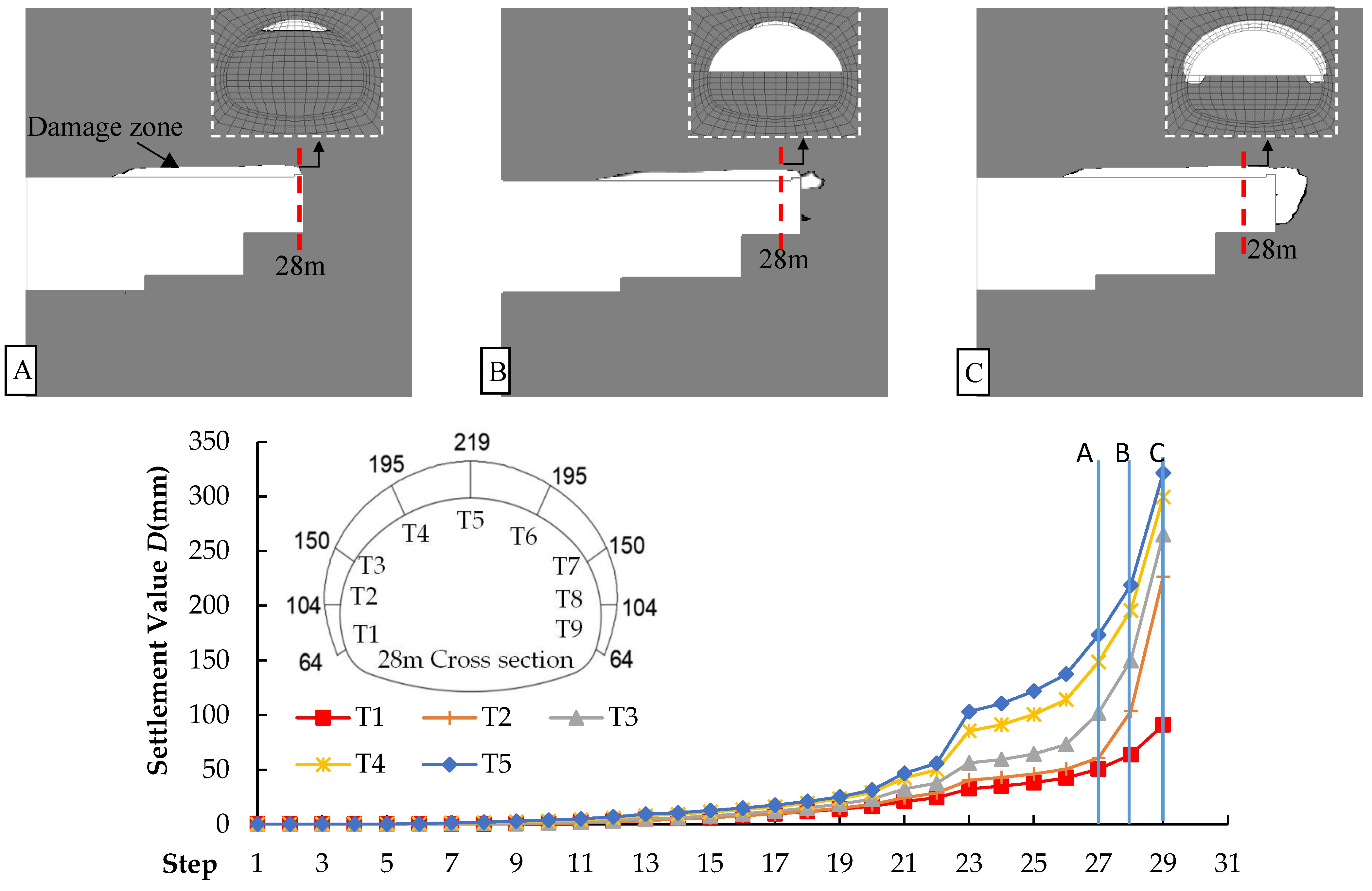
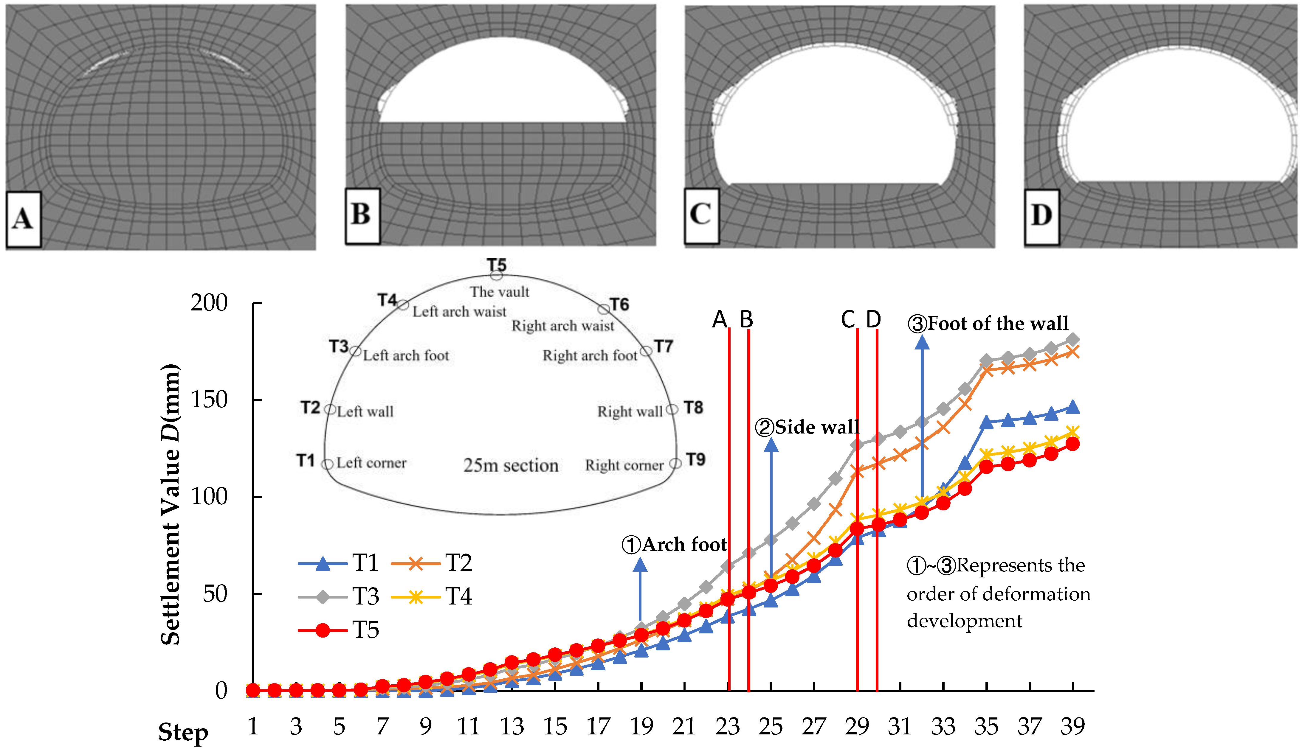
With the excavation process, the displacement of each monitoring point gradually increases with excavation, the deformation gradually develops from the arch foot to the wall foot (shown in 1~3 of Figure 5), and the deformation decreases in the order of arch foot, side wall, wall foot, arch waist, and arch. The total displacement is 181.2 mm, 175.0 mm, 146.5 mm, 133.3 mm, and 127.4 mm, respectively.
(2)
The failure area of the surrounding rock in the tunnel arch is much smaller. With the advancement of the excavation face to a deeper depth, the surrounding rock failure area mainly develops below the arch. The failure law is from the arch foot to the sidewall and, finally, to the wall foot.
In summary, under the pre-support effect of the advanced pipe shed, the stability of the two-step construction method of the tunnel in the V-grade surrounding rock stratum is significantly improved. The upper step face is almost not squeezed by the surrounding rock of the arch. The deformation and damage of the surrounding rock around the face are mainly concentrated in the sidewall area. It is verified that the two-step construction of the V-grade surrounding rock of the super large cross-section tunnel can effectively control the deformation of the face by using the advanced large pipe shed.

4.3. Analysis of the Pipe Roof Design Parameters

For different pipe shed reinforcement lengths and different pipe shed reinforcement ranges, the deformation calculation results of the surrounding rock and supporting structure at the Y = 25 m section are shown in Table 3.
The following can be seen from Table 3:
(1)
When the reinforcement range of the pipe roof increases from 90° to 180°, the arch settlement, horizontal convergence, and tunnel face displacement are significantly reduced, and the decreases are −59.4%, −52.0%, and −25.6%, respectively. The maximum displacement position of the surrounding rock around the tunnel gradually shifts from the arch foot to the sidewall and, finally, to the wall foot. The deformation of the supporting structure is also significantly reduced, which indicates that the pipe roof also reduces the deformation of the supporting structure by reducing the advanced deformation. From the perspective of displacement reduction caused by unit angle, it is more economical to adopt a reinforcement range of 120° for controlling the arch settlement and the displacement of the tunnel face, and a reinforcement range of 150° for controlling the convergence displacement is more economical.
(2)
The length of the pipe shed increases from 15 m to 30 m. Compared with 15 m, when the length of the pipe shed is 20 m, the advanced deformation of the surrounding rock, the settlement of the arch of the supporting structure, and the displacement of the tunnel face are significantly reduced, and the reductions are −15.5%, −24.1%, and −32.3%, respectively. Compared with the pipe shed lengths of 30 m and 20 m, the displacement of the pipe shed is basically unchanged, with a decrease of approximately 1% to 6%.

4.4. Analysis of Step Design Parameters

The deformation calculation results of the surrounding rock and supporting structure at Y = 25 m for different cycle footage, step length, and step height are shown in Table 4.
The following can be seen from Table 4:
(1)
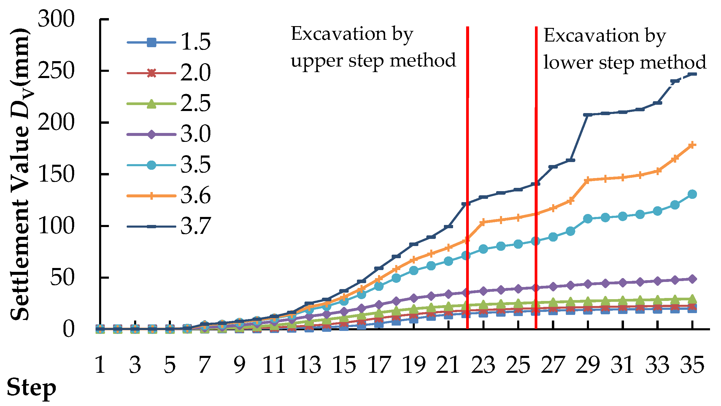
The adjustment of the circulation footage z mainly affects the settlement of the arch of the supporting structure. Compared with z = 0.5 m, when z is 1.5 m, the advanced deformation increases from 45 mm to 50 mm, the settlement of the arch of the supporting structure DV increases from 58 mm to 90 mm, and the deformation of the tunnel face DF increases from 137 mm to 161 mm, an increase of approximately 14.9%.
(2)
Adjusting the step length l mainly affects the settlement of the arch of the supporting structure. Compared with l = 4 m, when l is 8 m, the advanced deformation of the peripheral convergence increases from 42 mm to 60 mm, an increase of approximately 42.8%, and the deformation of the tunnel face DF decreases from 157 mm to 134 mm, a decrease of approximately −15.7%. The arch settlement of the supporting structure DV increased from 47 mm to 93 mm, an increase of approximately 97.8%.
(3)
Adjusting the step height h mainly affects the surrounding convergence of the supporting structure. Compared with h = 4 m, when h is 8 m, the surrounding convergence of the supporting structure DH increases from 20 mm to 61 mm, an increase of approximately 205%. The extrusion deformation of the tunnel face DF increased from 126 mm to 145 mm, an increase of approximately 15.1%.

5. Two-Step Method for Constructing a Super Large Cross-Section Tunnel in Karst Cave Development Stratum

5.1. Calculation Conditions

Based on the above research results and the case statistics of karst caves prone to mud inrush disasters, according to the stability of the surrounding rock and the development of karst caves, the advanced support measures and design parameters of IV- and V-grade surrounding rock, the design parameters of bench excavation, the initial support measures, and the treatment measures of karst caves, the construction of super large cross-section tunnels through karst caves is determined.
Advanced support measures and design parameters of IV-grade surrounding rock:
(1) The advanced small pipe with a length of at least 4.5 m is used to improve the stability of the surrounding rock.
(2) When the karst cave is developed in front of the tunnel arch [21], the partition advanced large pipe shed measure (only arranging the advanced large pipe shed in the range of the karst cave development in front of the tunnel arch) is adopted to improve the stability of the karst cave. The length of the advanced large pipe shed should pass through the karst cave and ensure that the depth of the rock is at least 2.5 m. The criterion for the development of filled karst caves in front of the tunnel arch is that the karst cave is within 120° of the tunnel arches, the size of the karst cave is greater than or equal to 50 m3, and the distance between the karst cave and the tunnel face is not more than 4 m.
Advanced support measures and design parameters of V-grade surrounding rock:
(3) Advanced pipe sheds should be adopted to improve the stability of the surrounding rock or karst caves. The length of the advanced pipe shed should be 20 m and the circumferential reinforcement range should be within 120° of the arches. The length of the advanced large pipe roof should be optimized according to the size of the karst cave, the location of the karst cave, and the type of filling material, according to the drilling records of the pipe roof. The length of the advanced large pipe roof should pass through the karst cave, and the depth of rock entry should be at least 2.5 m.
Design parameters of the step excavation:
(4) The step design parameters include step height, step length, and cycle footage. The step length should be 3~5 m, the step height should be 4~6 m, and the cycle footage should be 1~2 steel frame spacing.
(5) To avoid hanging the initial support of the upper step at the same time, the lower step should be excavated by a staggered platform. When the karst cave is exposed on the side of the upper step, the side of the karst cave should be excavated first when the lower step is staggered. The excavation of the lower step should be carried out after the construction of the upper step karst cave is completed.
(6) To provide construction conditions for karst cave construction, it is necessary to adjust the step design parameters. The height of the step should be increased so that the upper step can expose the cave vertically, and the height of the adjusted step should be less than or equal to 6 m. The length of the step should be increased so that the upper step can expose the longitudinal direction of the cave, and the adjusted step length can be greater than 5 m.
Initial support:
(7) After the excavation of the micro-step, the initial support construction is carried out quickly. The initial support construction includes measures such as tunnel face closure and shotcrete-anchor support. Among them, the closure of the tunnel face should be implemented when the deformation of the tunnel face is obvious, the side wall of the arch falls off a large number, the local collapse occurs, and the tunnel face cannot be stabilized. Shotcrete-anchor support includes a steel frame, steel pipe (φ ≥ 42 mm) grouting locking foot, shotcrete, system bolt, and so on.
Treatment measures of karst caves:
(8) The treatment of karst caves is mainly based on their scale, spatial position, and the type of filling material provided by geological exploration and construction geological forecasts. When the large filling karst cave (more than 50 m3) is in the arch and sidewall, the advanced treatment is carried out by means of a large pipe shed or surface grouting. For other cases of large karst caves and small karst caves (less than 50 m3), cleaning, sealing, and backfilling measures are mainly used for post-processing.

5.2. Construction Process

In view of the two-step method construction for constructing super large cross-section tunnels crossing the karst cave area, according to the stability of surrounding rock and the development of karst caves, the following construction process is formulated:
(1)
Advanced geological prediction and sketching of the tunnel face are carried out on the tunnel face to confirm the grade of the surrounding rock and the condition of the surrounding rock in front.
(2)
The karst development is judged according to the surrounding rock conditions, and the advanced support measures and design parameters are determined according to the surrounding rock grade and karst cave development.
(3)
The hole-forming and charging operations are carried out in the upper and lower steps. The upper and lower steps are blasted at the same time, and the excavation is carried out in parallel. The design parameters of the steps should meet the requirements of large-scale mechanical operation space under the condition of ensuring the stability of the surrounding rock.
(4)
The fan is opened to discharge the dust in the hole, and the excavator is used to carry out the dangerous rock discharge under excavation treatment around the hole. The excavator cooperates with the mucking truck to carry out the mucking operation. After the dust is discharged, geological sketching is carried out on the face of the tunnel. According to the results of the geological sketch, the karst cave treatment and the initial support construction are carried out.
(5)
According to the geological sketch results, the advanced support measures and design parameters of the next cycle and the design parameters of the steps are adjusted.
The construction process is shown in Figure 6.

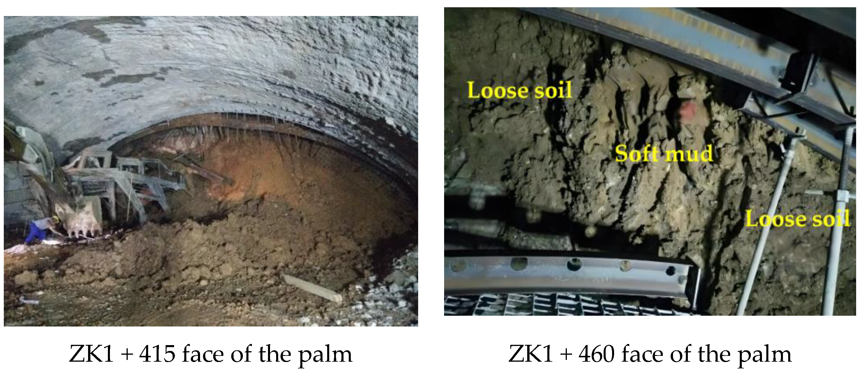
6. Engineering Applications

Through the application of the two-step construction method of the super large cross-section tunnel in the karst cave development stratum, the Lianhuashan Tunnel adopts the advanced large pipe shed and two-step method in the V-grade surrounding rock (soil) stratum (poor stability of the tunnel face) in the soil-rock composite stratum section. In the V-grade surrounding rock (mainly bedrock) stratum (good stability of the tunnel face) and the IV-grade surrounding rock stratum, the construction method of the advanced small pipe and two-step method is adopted, and the advanced large pipe shed adopts the self-propelled pipe shed process, which has achieved good surrounding rock deformation control and karst cave stability control effect [22]. The monthly excavation progress of the single working face of the tunnel in the IV- and V-grade surrounding rock sections of the tunnel reaches 44~54 m/month.

6.1. V-Grade Surrounding Rock Step Method Construction

ZK1 + 358~ZK1 + 523 on the left line of the entrance of the Lianhuashan Tunnel is in the shallow buried section. The surrounding rock of this section is mainly hard plastic red clay, and the clay and weathered limestone are interlaced, as shown in Figure 7. The advanced support of this section adopts a φ76 self-propelled advanced large pipe shed, and the specific implementation of the advanced large pipe shed is shown in Table 5. Among them, four sections, ZK1 + 382~ZK1 + 402, ZK1 + 415~ZK1 + 435, ZK1 + 460~ZK1 + 490, and ZK1 + 493~ZK1 + 523 have developed karst caves, and some of the pipe sheds have been lengthened to penetrate the karst cave and reach a depth of 4 m.
Taking ZK1 + 382~ZK1 + 402 as a typical example, the construction scheme of the two-step method for V-grade surrounding rock is described in detail as follows:
(1)
The geological radar is used to detect the range of 30 m in front of the tunnel face in the ZK1 + 382 section. The arch line map shows that the radar wave reflection is strong in the 9~15 m section in front of the tunnel face, which may develop large-scale karst caves, groundwater is not developed, and the surrounding rock level is V-grade.
(2)
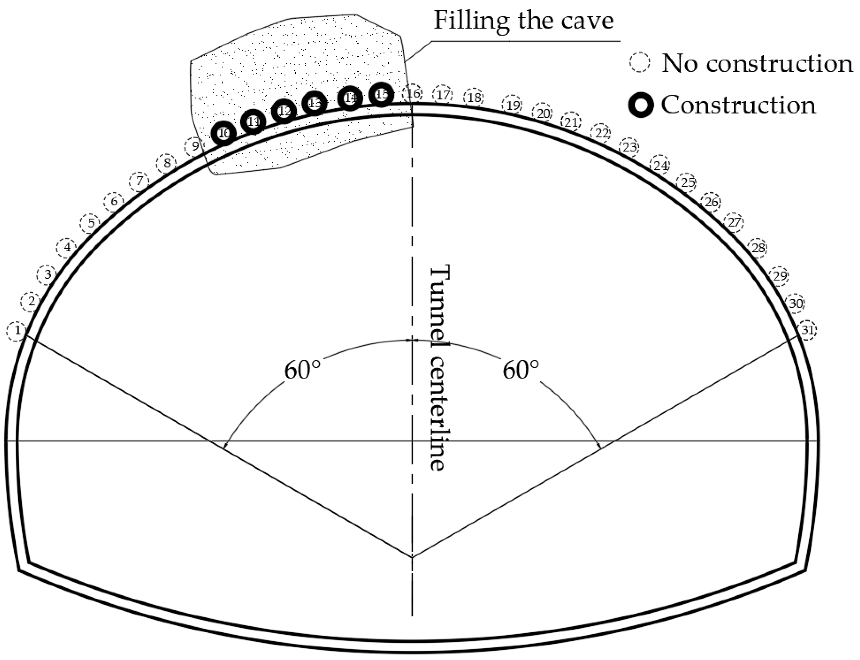
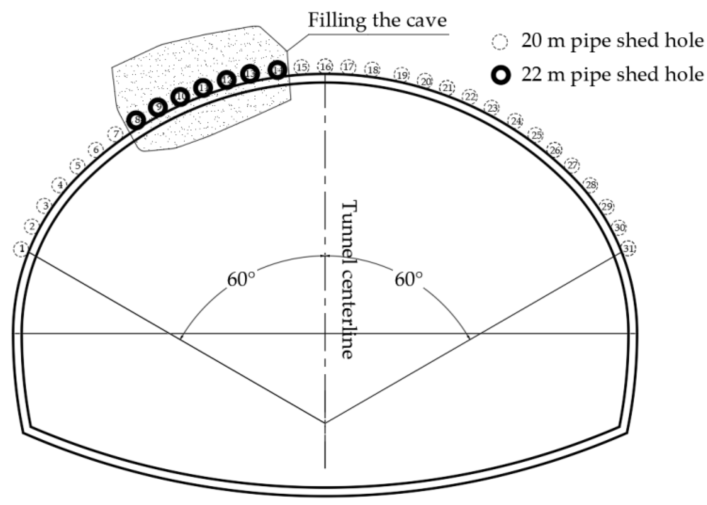
According to the conditions of the surrounding rock and the development of the karst cave, the advanced support adopts the advanced large pipe shed. The design length of the advanced large pipe shed is 20 m, and the circumferential reinforcement arch is 120°. A total of 31 holes were arranged. Through the analysis of the drilling records of the pipe shed, the 11~18 m section of 8~14 holes are filled with karst cave, so the length of 8~14 holes is extended to 22 m. The layout of the advanced large pipe shed is shown in Figure 8.
(3)
The upper steps and lower steps are excavated in parallel. The length of the step is 4 m, the height of the step is 5 m, and the cyclic footage is the spacing of 2 steel frames.
(4)
After the ventilation and mucking operation, the geological sketch results show that the 3 m × 3 m × 5 m (length, width, height) semi-filled silty clay karst cave is exposed on the left sidewall of the lower step, and the primary support is closed after cleaning the filling and concrete backfilling. The tunnel face is relatively stable, there is no obvious extrusion deformation, and there is a small amount of falling blocks. The initial support adopts HW200 × 200H steel, a 3.5 m-long φ42 mm grouting steel pipe lock foot, C20 thick 29 cm early strength shotcrete, and a 5.0 m-long φ22 mm cartridge bolt.
During the construction process, 14 monitoring sections were arranged in the ZK1 + 358~ZK1 + 523 section (as shown in Figure 9). The arch settlement of the ZK1 + 400 section was the largest at 74.2 mm, followed by 51.2 mm of the ZK1 + 410 section, and 4.3~17.2 mm in the other sections. The deformation of the tunnel support structure is controllable. The two-step method and advanced large pipe roof measures adopted in this section have a significant effect on tunnel deformation control.

6.2. IV-Grade Surrounding Rock Bench Method Construction

The surrounding rock of the ZK1 + 950~ZK2 + 850 (YK1 + 900~YK2 + 850) section of the Lianhuashan Tunnel is mainly composed of limestone and siliceous limestone with mudstone, and the surrounding rock grade is IV. There may be hidden karst caves in the bedrock, and mud inrush and other disasters may occur. The TSP is used for detection every 100 m in this section. After roughly determining the distribution of bad geology in front of the tunnel face, a geological radar is used for detection once it is close to approximately 30 m from the bad geological body to further verify and understand the distribution of bad geology. Taking the ZK2 + 155 section as a typical example, the construction scheme of the two-bench method for IV-grade surrounding rock is described in detail.
(1)
In the range of 30 m in front of the tunnel face, the geological radar is used for detection. The arch line map shows that there is a strong radar reflection section in the 3~9 m section in front of the tunnel face, so it is speculated that there is a large-scale cavity in this section. The sidewall survey line map shows that there is a strong radar reflection section in the front 2~5 m section, so it is speculated that there may be a weak interlayer or cavity in this section. The surrounding rock is IV-grade.
(2)
According to the condition of the surrounding rock and the development of the karst cave, it is judged that the advanced support adopts φ42 advanced small pipe and φ76 partition advanced large pipe shed. The design length of the advanced small pipe is 4.5 m, the circumferential spacing is 40 cm, the extrapolation angle is 10°, the arch is 120°, and the lap length is greater than 1.0 m. The preliminary determination range of the partition advanced large pipe roof layout is 30° on the left side of the arch. Then, according to the analysis of the pipe roof drilling records, the 4–11 m section of 10–15 holes is determined as the filling karst cave. The final partition advanced large pipe roof layout scheme is 10–15 holes with a length of 15 m. The partition advanced large pipe roof layout is shown in Figure 10.
(3)
The length of the step is 5 m, the height of the step is 5 m, and the cyclic footage is two steel frames. The upper steps and lower steps are excavated in parallel.
(4)
After the ventilation and mucking operation, the geological sketch results show that the tunnel face is unstable, the extrusion deformation of the tunnel face is obvious, and there is a local collapse phenomenon. The tunnel face is closed by 20 cm-thick shotcrete. The initial support adopted I20 b I-shaped steel, a 3.5 m-long φ42 mm grouting steel pipe locking foot, C20 thick 25 cm early strength shotcrete, 4.0 m long φ22 mm cartridge anchor rods. The 2 m × 2 cm × 3 cm (length, width, height) semi-filled silty clay karst cave was exposed on the left arch foot of the upper step, and the primary support was closed after cleaning the filling and concrete backfilling.
(5)
According to the exposed conditions of the karst cave and the state of the tunnel face, the length and height of the next cycle step are adjusted according to the longitudinal and vertical ranges of the karst cave. The adjusted step length can be greater than 5 m, and the step height should be less than or equal to 6 m. In the next cycle, the leading small pipe is adjusted to a φ42 double-layer length of 6.0 m, circumferential spacing of 40 cm, extrapolation angle of 10°, and arch range of 120°.
Figure 10. The layout diagram of the advanced large pipe roof in the partition.
Applsci 14 04500 g010

7. Conclusions

By comprehensively analyzing the above numerical analysis results and engineering application results, the conclusions are as follows:
(1)
When the advanced small pipe measures are adopted, the tunnel face can be self-stabilized during the construction of the IV-grade surrounding rock of the super-large cross-section tunnel by the two-step method. However, the tunnel face of the V-grade surrounding rock section of the super large cross-section tunnel is easily unstable. The surrounding rock in the range of about 4.5 m in front of the tunnel face and about 1.5 m above the arch has collapsed, and the advanced influence distance is approximately 20 m. The countermeasures should be mainly based on the tunnel face for stability control.
(2)
The adoption of advanced large pipe shed measures can significantly improve the construction stability of the two-step method in the V-grade surrounding rock section of the super large cross-section tunnel. The reasonable design parameters of the advanced large pipe shed can improve the economy and construction speed of the measures. A reinforcement range of 120° is more economical for controlling the arch settlement and the displacement of the tunnel face, and a reinforcement range of 150° is more economical for controlling the convergence displacement. The deformation control effect is the best when the pipe shed length is 20 m. Shortening the step cycle footage can significantly reduce the arch settlement of the supporting structure. Reducing the step length can significantly reduce the arch settlement of the supporting structure but increase the extrusion deformation of the tunnel face. Reducing the step height can significantly reduce the surrounding convergence of the supporting structure.
(3)
The stability of the surrounding rock and karst cave should be controlled at the same time during the construction of the super large cross-section tunnel crossing the IV-grade and V-grade surrounding rock section in a karst cave area. According to the conditions of the surrounding rock and the development of karst caves, advanced support measures and two-step excavation should be adopted according to the classification. Among them, the IV-grade surrounding rock adopts the advanced small pipe to control the stability of the surrounding rock, and the arch and large-scale filling karst cave are treated in advance by partition advanced pipe shed measures. The V-grade surrounding rock adopts an advanced large pipe roof to control the stability of the surrounding rock and karst cave. After the excavation of the micro-step, the primary support is quickly closed to control the deformation of the support, and the exposed karst cave is treated by measures such as closure and concrete backfilling.
The application of this construction method in the Lianhuashan Tunnel has achieved a good control effect of surrounding rock deformation and karst cave stability and significantly improved the monthly excavation progress of the single working face of the tunnel in IV-grade and V-grade surrounding rock sections. However, in engineering practice, there is still much room for improvement in the construction speed and economy of this construction method from the two aspects of the rapid construction technology of the advanced large pipe shed and the construction method of the advanced large pipe shed partition, which needs to be further studied in future work.

Author Contributions

Conceptualization, F.W. and N.Z.; methodology, G.L., Y.T., N.Z. and F.W.; software, D.X., X.Y. and S.L.; formal analysis and investigation, N.Z., G.L., Y.T. and F.W.; writing—original draft preparation, F.W., N.Z., D.X., X.Y. and S.L.; writing—review and editing, F.W., N.Z., D.X., X.Y. and S.L.; funding acquisition, N.Z. and F.W.; and resources, F.W., G.L. and Y.T. All authors have read and agreed to the published version of the manuscript.

Funding

This research is supported in part by the Pilot Project of Country with Strong Transportation Network of Research Institute of Highway Ministry of Transport (No. QG2021-3-14-1), in part by the Central Government Guides Local Science and Technology Development Fund Project (No. YDZJSX20231A021), and in part by the Shanxi Province Graduate Practice and Innovation Project (No. 2023SJ070).

Institutional Review Board Statement

Not applicable.

Informed Consent Statement

Not applicable.

Data Availability Statement

The raw data supporting the conclusions of this article will be made available by the authors on request.

Acknowledgments

The authors are grateful for the comments provided by the anonymous reviewers.

Conflicts of Interest

Author Yifeng Tang was employed by the company Rioh Traffic Safety Co., Ltd. The remaining authors declare that the re-search was conducted in the absence of any commercial or financial relationships that could be construed as a potential conflict of interest.

References

  1. Wu, S.; Li, L.; Ren, G.; Xia, C.; Wang, X. Study on Comparison and Selection of Excavation Method for Tunnel with Super Large Section and Shallow Buried Broken Surrounding Rock. Chin. J. Undergr. Space Eng. 2023, 19, 794–803. [Google Scholar]
  2. Luo, Y.; Shi, Z.; Chen, J.; Liu, W.; Chen, L.; Li, Y.; Wu, Y. Mechanical Calculation Model and Research on Construction Mechanical Behavior of Middle Diaphragm in Upper Bench CD Method for Super-large Span Tunnel. China J. Highw. Transp. 2020, 33, 235–248. [Google Scholar] [CrossRef]
  3. Hou, F.; Sun, K.; Zhao, R.; Zhou, H.; Xu, W.; Zhou, Z. Applicability study on construction method of super-large section neighborhood tunnel. China Civ. Eng. J. 2017, 50, 111–116. [Google Scholar]
  4. Zhang, J.; Wu, J.; Yan, C.; Gou, X.; Ye, L.; Feng, J. Construction Technology of Super Large Section of Highway Tunnels with Four or More Lanes in China. China J. Highw. Transp. 2020, 33, 14–31. [Google Scholar] [CrossRef]
  5. Zhou, J.; Zou, G.; Peng, H. Construction Method for Large Section Deep-buried Rail Transit Stations: Bench Cut Method with Expanded Arch Feet. Urban Rapid Rail Transit 2023, 36, 117–123. [Google Scholar]
  6. Cui, L.; Zheng, J.; Zhang, R.; Yu, S. Analysis of deformation of the surrounding rock and preliminary Support stress in tunnels through weak and cracked strata. J. Huazhong Univ. Sci. Technol. Nat. Sci. Ed. 2012, 40, 53–57. [Google Scholar]
  7. JTG/T 3660-2020; Technical Specifications for Construction of Highway Tunnel. China First Highway Engineering Co., Ltd.: Beijing, China, 2020.
  8. Song, S.; Li, S.; Li, L.; Liu, Q.; Yuan, X.; Shi, S. Study on Rules of Mechanical Effect in Process of Construction of Super-large Cross-section Tunnel in Weak and Broken Surrounding Rock Excavated by Bench Method. Tunn. Constr. 2011, 31, 170–175. [Google Scholar]
  9. Zou, C.; Shen, Y.; Jin, Z. Study of Bench Method’s Geometric Parameters Optimization in Weak Broken Wall Rock and Large Cross-section Tunnel. Highw. Eng. 2013, 38, 27–31+35. [Google Scholar]
  10. Wu, J.; Chen, J.; Ma, J.; Song, Y.; Zhou, C.; Guo, S.; Sun, Y. Design and Fast Construction Technology for Large-Cross-Section Tunnel in Water-Rich Fracture Zone. Tunn. Constr. 2022, 42, 353–359. [Google Scholar]
  11. Li, W.; Sun, M.; Zhu, Y.; Zhu, Z.; Li, Y. Arch springing stability and its control techniques during construction of tunnels with weak surrounding rocks by bench cut method. Chin. J. Rock Mech. Eng. 2012, 31, 2729. [Google Scholar]
  12. Luo, Y.; Chen, J. Mechanical characteristics and mechanical calculation model of tunnel feet-lock bolt in weak surrounding rock. Chin. J. Geotech. Eng. 2013, 35, 1519. [Google Scholar]
  13. Zou, Y. Study on Stability of Tunnel Face and Optimization of Advance Support Parameters in Soft Rock Tunnel by Large Cross-Section Construction. Master’s Thesis, Guangxi University, Nanning, China, 2023. [Google Scholar]
  14. Yuan, X. Study on Construction Process Optimization of Ultra-large Section Tunnel with Soft and Fractured Surrounding Rock and Its Application. Master’s Thesis, Shandong University, Jinan, China, 2012. [Google Scholar]
  15. Liu, L.; Zheng, Y.; Zhang, Z. Numerical Simulation Study on Influence of Existing Top Karst Cave on Stability of Tunnel Surrounding Rock. Mod. Tunn. Technol. 2023, 60, 86–95. [Google Scholar]
  16. Zhang, G.; Ye, S.; Zeng, B.; Zhao, K. Influence of Concealed Cave Group in Fault Zone on Stress Characteristics of Tunnel Lining and Comparison of Construction Methods. Mod. Tunn. Technol. 2023, 60, 65–73. [Google Scholar]
  17. Li, K.; Duan, Z.; Guo, D.; Zeng, B.; Wang, Q. Study on Influence of Different Azimuth Angles of Concealed Karst Cave on the Stress Characteristics of Tunnel Lining Structure. Mod. Tunn. Technol. 2023, 60, 74–85. [Google Scholar]
  18. Xu, H.; Geng, H.; Li, C.; Chen, W.; Wang, C. Estimating strength of grouting reinforced bodies in broken rock mass. Chin. J. Geotech. Eng. 2013, 35, 2018–2022. [Google Scholar]
  19. Zheng, Y.; Qiu, C.; Zhang, H.; Wang, Q. Exploration of stability analysis methods for surrounding rocks of soil tunnel. Chin. J. Rock Mech. Eng. 2008, 27, 1968–1980. [Google Scholar]
  20. Wang, B. Analysis of the development law of karst in Lianhuashan Tunnel. Highway 2019, 64, 226–230. [Google Scholar]
  21. Wan, F. A Method for Detecting and Treating Large Karst Caves in Advance in Tunneling. Chinese Patent No. ZL2019113212631, 30 March 2021. [Google Scholar]
  22. Li, L.; Wang, B.; Fu, Z.; Wang, F. Experimental study on selection of advanced pipe shed in Lianhuashan Tunnel. China Foreign Highw. 2022, 42, 179–182. [Google Scholar]
Figure 1. Engineering geological profile.
Applsci 14 04500 g001
Figure 2. Model grid.
Applsci 14 04500 g002
Figure 3. Variation curve of surrounding rock arch settlement under different reduction coefficients.
Applsci 14 04500 g003
Figure 4. The development law of deformation and failure of surrounding rock in tunnel construction by two-step method. Note: (AC) represent the failure zone of the 28 m research section when the tunnel face is excavated to 27 m, 28 m, and 29 m, respectively.
Applsci 14 04500 g004
Figure 5. Development law of surrounding rock deformation and failure during advanced pipe roof support.
Applsci 14 04500 g005
Figure 6. Construction flow chart.
Applsci 14 04500 g006
Figure 7. Typical surrounding rock of tunnel face.
Applsci 14 04500 g007
Figure 8. The layout diagram of the advanced large pipe roof.
Applsci 14 04500 g008
Figure 9. The arch settlement of each monitoring section.
Applsci 14 04500 g009
Table 1. Physical and mechanical parameters of surrounding rock and supporting materials.
MaterialGravity
γ (kN/m3)
Elastic Modulus E (GPa)Poisson’s Ratio
ν
Force of Cohesion f (MPa)Friction Angle
φ (°)
Surrounding rock236.00.250.1039
Initial support2631.40.202.2753
Table 2. The proportion of surrounding rock arch settlement under different reduction coefficients.
Construction StageReduction Factors
1.52.02.53.03.53.63.7
Advanced deformation51.1%63.5%67.3%61.9%43.5%37.6%33.3%
Excavation of upper steps34.7%23.3%18.3%18.6%19.5%22.8%21.4%
Excavation of lower steps14.3%13.2%14.4%19.6%37.1%39.6%45.3%
Table 3. Calculation results under different design parameters of advanced large pipe shed.
ProjectSurrounding RockSupporting StructureDisplacement of Tunnel Face
DF (mm)
Arch Settlement DV (mm)Horizontal Convergence
DH (mm)
Arch Settlement DV (mm)Horizontal Convergence
DH (mm)
Reinforcement range
(°)
90−155123−9662−160
120−115117−6561−145
150−8385−4424−133
180−6359−2934−119
Reinforcement length
(m)
15−202124−11273−368
20−161113−8567−247
25−160111−8568−230
30−159116−8365−227
Table 4. Calculation results of different step design parameters.
ProjectSurrounding RockSupporting StructureDisplacement of Tunnel Face
DF (mm)
Arch Settlement DV (mm)Horizontal Convergence
DH (mm)
Arch Settlement DV (mm)Horizontal Convergence
DH (mm)
Cycle footage
z (m)
0.5−103107−5856−161
1.0−115117−6561−145
1.5−140124−9062−137
Step length
l (m)
4.0−9399−4757−157
6.0−115117−6561−145
8.0−143133−9373−134
Step height
h (m)
4.0−9880−5720−126
5.0−10286−5855−132
6.0−115117−6561−145
Table 5. The construction quantity of the advanced large pipe shed.
SectionNumber/Hole NLength L (m)
ZK1 + 358~ZK1 + 3734115
ZK1 + 367~ZK1 + 3874220
ZK1 + 382~ZK1 + 4024220/22
ZK1 + 398~ZK1 + 4184220
ZK1 + 415~ZK1 + 4354220/25
ZK1 + 433~ZK1 + 4634220
ZK1 + 460~ZK1 + 4904820/25
ZK1 + 493~ZK1 + 5233720/25
Disclaimer/Publisher’s Note: The statements, opinions and data contained in all publications are solely those of the individual author(s) and contributor(s) and not of MDPI and/or the editor(s). MDPI and/or the editor(s) disclaim responsibility for any injury to people or property resulting from any ideas, methods, instructions or products referred to in the content.

