Abstract
The working environment of mining electric locomotives is wet and muddy coal mine roadway. Due to low friction between the wheel and rail and insufficient utilization of creep rate, there may be idling or slipping between the wheels and rails of mining electric locomotives. Therefore, it is necessary to control the creep rate within a reasonable range. In this paper, the autonomous control algorithm for mining electric locomotives based on improved -greedy is theoretically proven to be convergent and effective firstly. Secondly, after analyzing the contact state between the wheel and rail under wet and slippery road conditions, it is concluded that the value of creep rate is an important factor affecting the autonomous driving of mining electric locomotives. Therefore, the autonomous control method for mining electric locomotives based on creep control is proposed in this paper. Finally, the effectiveness of the proposed method is verified through simulation. The problem of wheel slipping and idling caused by insufficient friction of mining electric locomotives in coal mining environments is effectively suppressed. Autonomous operation of vehicles with optimal driving efficiency can be achieved through quantitative control and utilization of the creep rate between wheels and rails.
1. Introduction
Mining electric locomotives have the transportation function of materials, equipment, and people in roadway. Safe driving of mining electric locomotives is crucial. However, the method of underground mining is often used in the Chinese coal mining industry [1]. In deep underground confined spaces, there are unfavorable conditions for driving in coal mine roadway, such as slippery, muddy, dusty, foggy, and complex human behavior, which lead to frequent accidents. Reducing personnel participation and ensuring the safe operation of production and transportation equipment are necessary to ensure the safety production of coal mines. At present, the intelligent development of coal mine equipment has become an inevitable trend [2]. Unmanned transportation of coal mine equipment can fundamentally solve the problem of personnel participation and reduce casualties in the event of inevitable accidents. We have conducted relevant research on autonomous mining electric locomotives [3]. The mining electric locomotive has achieved functions based on Reinforcement Learning (RL) and improved -greedy such as autonomous and efficient operation on speed limited sections, maintaining a safe distance from vehicle in front, and avoiding obstacles.
However, problems such as slipping of autonomous vehicles and wheel idling caused by slippery roadway in deep mines have not been addressed in a targeted manner. Manually driven mining electric locomotives rely on the driver’s experience to sprinkle sand to increase wheel rail friction. But this method is a remedial measure taken when slipping/idling occurs during driving. And there is no quantitative evaluation standard for actions judged by human subjectivity. Moreover, actions based on human subjective judgment cannot be used as a quantifiable evaluation criterion applicable to machine autonomous decision-making. In the autonomous driving control process of mining electric locomotives, it is necessary to make decisions that can actively control the interaction between wheels and rails to prevent slipping, idling, and other phenomena caused by external environment.
For rail vehicles, the destruction of the adhesion between the wheel and rail is the basic reason of wheel slip/idling [4]. One of the reasons for the traction and braking forces of wheelsets is the presence of contact and friction between the wheel and rail [5]. This kind of wheel rail interaction force is not pure friction, but a phenomenon called creep caused by deformation after wheel rail contact [6]. Reasonably utilizing the creep rate can improve the efficiency and safety of vehicle operation [7]. Nowadays, to prevent train wheel slipping or idling, scholars have conducted research on algorithms related to adhesion control. According to different control methods, adhesion control algorithms are generally divided into re-adhesion control and optimized adhesion control [8]. Re-adhesion control is a method that can quickly adjust the motor torque to achieve balance with the current adhesion conditions, and avoid wheel idling when determining whether the locomotive’s wheels are idling/slipping. The research on this method is relatively mature [9,10,11], but it belongs to passive adhesion control method, with a low adhesion utilization rate and long algorithm response time. The purpose of optimizing adhesion control is to achieve the peak point of the optimal adhesion utilization, which is of great significance for the operation control of trains under wet, muddy and emergency braking conditions. Mehmet Ali Çimen et al. [12] analyzed the input and output phase shift dynamic characteristics of the traction system. They also proposed an adaptive control method that effectively controls the adhesion utilization rate of the traction system. Song Wang et al. [13] proposed an adhesion control method based on optimal torque search for high-speed trains, which can achieve stable operation of trains in the optimal adhesion state under changes of track surface and high-speed driving conditions, effectively reducing the idle rate of the wheel and improving train adhesion utilization. Shuai Zhang et al. [14] proposed a sliding mode control method, which used recursive least squares method based on enhanced forgetting factor to solve the problem of wheel anti lock on heavy-duty trains. This algorithm can obtain the optimal creep rate and construct a PI closed-loop observer to estimate the unmeasured adhesion torque, enabling the locomotive to adjust to the optimal creep rate when the contact of wheel and rail changes. The optimized adhesion control algorithm can suppress the sliding and idling of the wheel. However, the maximum adhesion point in the contact area of wheel and rail is at the junction of creep and sliding, making it difficult to ensure that the contact state of wheel and rail is always creep during the actual control process. Therefore, this method still belongs to passive adhesion control. In addition, there are certain differences in the utilization of adhesion capacity among the axles of the train. The existing methods have insufficient control accuracy, as most of the adhesive characteristic curves relied on are empirical formulas obtained through experiments.
Therefore, this paper proposes a creep control method for mining electric locomotives based on RL. This method converts the impact of complex driving environments on mining electric locomotives into reward feedback values obtained by the electric locomotives from the environment. The impact of creep conditions that are difficult to quantify and evaluate on vehicles has been particularly considered in this method. The optimal range of creep rate is tried to achieve after training the mining electric locomotive to adjust the driving torque of the wheelset in this method. To achieve maximum driving efficiency under safe operating conditions is the goal of this method.
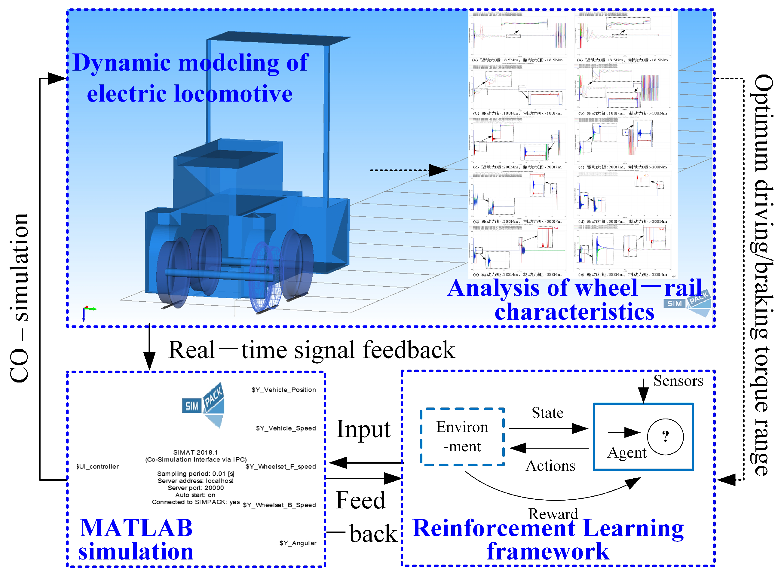
The overall structure of this paper is shown in Figure 1. Firstly, the autonomous control method of mining electric locomotives based on improved -greedy is analyzed from the theoretical perspective. By changing environmental variables and replicating algorithms, the important factor affecting the operation of mining electric locomotive on wet and slippery tracks is identified. Secondly, a mining electric locomotives autonomous control algorithm based on creep control is proposed, which can effectively improve the safety and reliability of autonomous driving of mining electric locomotives. Finally, based on the three-dimensional dynamic model of mining electric locomotives modeled using Simpack, the feasibility of the proposed algorithm is verified using a multi software (PyCharm2021, MATLAB R2014b and Simpack 2018) co-simulation platform.
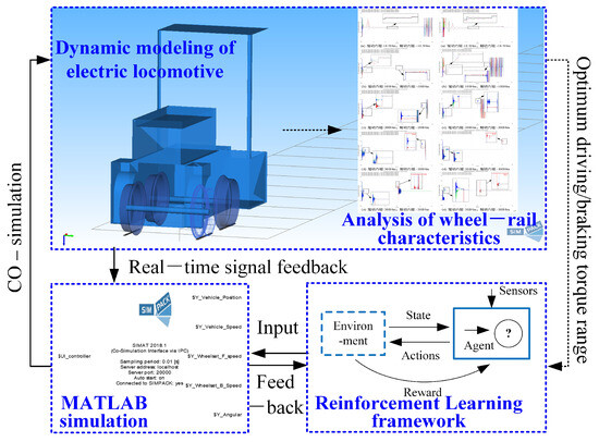
Figure 1.
The framework of creep control method for autonomous driving of the mining electric locomotive.
Compared to [3], this paper identifies the creep rate, a key factor affecting the autonomous operation of mining electric locomotives, through theoretical verification of the algorithm and practical analysis of operating conditions. This paper also proposes a creep control method suitable for mining electric locomotives, which improves the accuracy of autonomous operation control for mining electric locomotives.
2. Analysis of Autonomous Control Algorithm for Mining Electric Locomotives
In this section, an important factor is found through theoretical analysis and simulation, which was not particularly considered in the previous algorithm design but affected the autonomous driving of mining electric locomotives. First, in reproducing the autonomous control algorithm of mining electric locomotives based on RL, we find that changing the friction between the wheels and rails can lead to poor control performance. Second, this algorithm has been theoretically proven to be reasonable and convergent. Mining electric locomotives can stably achieve autonomous driving under the control of this algorithm. Third, the relationship between creep rate and adhesion coefficient of rail vehicles is analyzed. It is necessary to take the creep rate between the wheel and rail into the autonomous control algorithm. Finally, we conclude that the improved control objective is to achieve the optimal control range of creep rate.
2.1. Problem Formulation
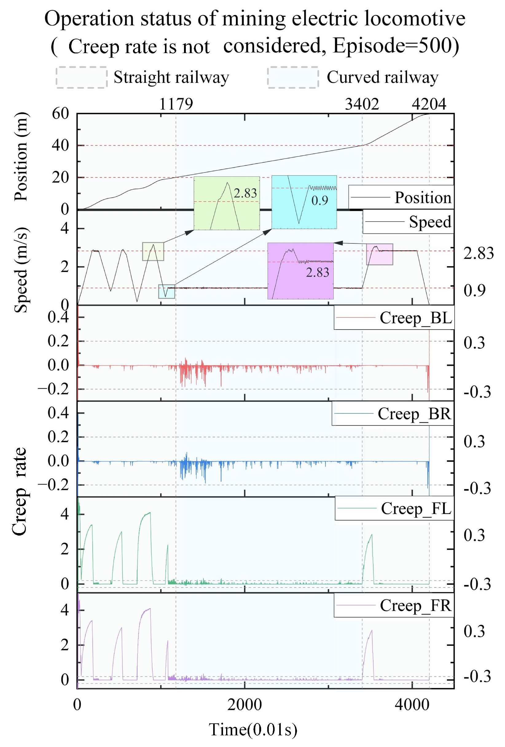
As shown in Figure 2, RL was adopted to solve the autonomous control problem of mining electric locomotives, and the -greedy strategy was improved to balance the relationship of exploration and exploitation better in reference [3]. This control method is reproduced in this paper on the condition that the friction of wheel and rail is adjusted from 0.4 to 0.3. Under this working condition, the autonomous control state curve of the mining electric locomotive shown in Figure 3 is obtained. It can be seen that mining electric locomotive operates safely and efficiently on speed limited sections, and can maintain a safe distance from obstacles when using the autonomous control method based on the improved -greedy strategy. However, it is found that the mining electric locomotive is unable to control the acceleration duration correctly when accelerating and reaching the maximum speed limit, and the running speed of the electric locomotive would slightly exceed the maximum speed limit. Moreover, the mining electric locomotive cannot control the deceleration duration to reach the maximum speed on the next speed limit section when decelerating.

Figure 2.
Improved -greedy strategy [3].
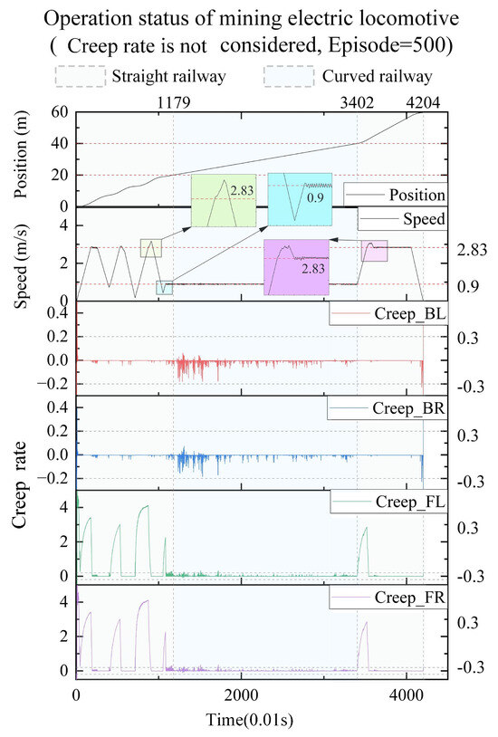
Figure 3.
The autonomous control state curve of the mining electric locomotive without creep control.
2.2. Theoretical Analysis
In order to find out the reasons for the problem above, we first verify whether the algorithm structure is designed reasonably from the perspective of algorithm theory. If the structural design is reasonable, the results of the algorithm will tend to converge with the training process of the agent. In this section, the convergence of the algorithm is demonstrated from two aspects: RL and improved -greedy strategy.
2.2.1. Reinforcement Learning
RL is a method for studying how an agent maximizes its reward in a complex and uncertain environment [15,16]. Figure 4 shows the process of RL. The agent interacts with the environment, obtains the current state and reward at moment t, and takes action based on certain strategies. After the agent takes action , the environment obtains the latest state and reward at moment t + 1, and passes them to the agent. This interaction process can be represented by the Markov Decision Process (MDP).
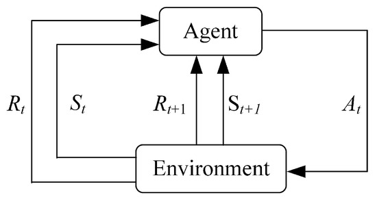
Figure 4.
Reinforcement Learning.
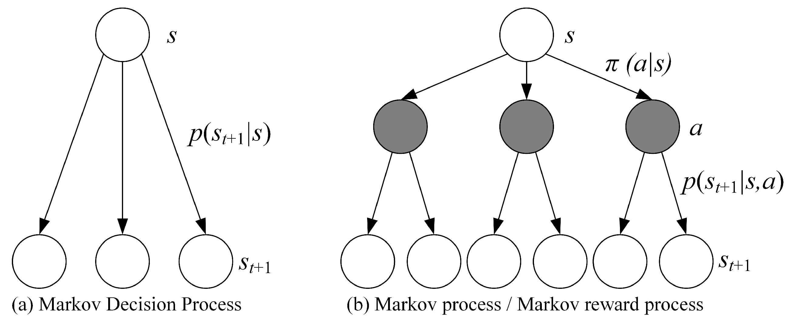
The MDP adds a decision layer to the commonly used Markov Process/Markov Reward Process, which is the action a shown in the Figure 5. This means that when the agent is in the state at time t, it must first decide on a specific action a to take in order to reach the middle layer, which is the black node in the diagram. After reaching the black node, the state of the agent at the moment t+1 also depends on the probability distribution.
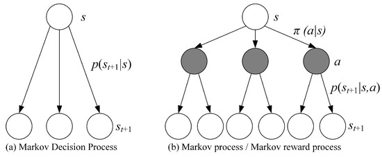
Figure 5.
The Markov Decision Process and Markov Process/Markov Reward Process.
RL, as a trial and error learning method, continuously repeats the above interaction process between agents and the environment to find a mapping that can maximize the cumulative sum of benefits over time.
where, T is the total time, is the discount factor.
However, the sum of cumulative returns, also known as value return , is not easily obtained. To solve this problem, researchers propose two value functions for estimating the sum of cumulative returns: the state value function and the action value function . The state value function is the expected value of the sum of the reward functions under strategy and s state. The action value function represents the expected value of the sum of the benefit functions of action a under the strategy and s state.
where, is the set of action a.
According to the value function, the Bellman equation is derived as follows:
where, is the set of state s.
The Bellman equation for the Q-function is as follows:
We adopt Theorem - Cauchy’s convergence Test to verify the convergence of RL we design to apply in the field of autonomous control of mining electric locomotives. The specific steps to prove the convergence of RL are detailed in Appendix A.
The RL algorithm focuses on the feedback information obtained by the agent from the environment for decision-making, without relying on the agent and the environment model. This method does not require modeling of the intelligent agent, directly avoiding control bias caused by inaccurate modeling. In addition, this algorithm idea enables the algorithm proposed in this paper to be applicable to different types of mining electric locomotives driving on different road sections. So this method is universally applicable in complex mine conditions. The method proposed in this paper is applied in the actual field based on the results of laboratory simulation training, which greatly reduces the debugging time of the algorithm in the actual application process.
2.2.2. Improved -Greedy
In reference [3], in order to balance the relationship between exploration and exploitation, the traditional -greedy algorithm was improved by changing the value of in Formula (6) to the value of in Formula (7).
For the improved -greedy, the selection of actions follows the following rules:
We can obtain the probability distribution of whether an action is the optimal action:
The specific steps to prove the convergence of improved -greedy strategy are detailed in Appendix B.
In summary, RL and improved -greedy strategy applied to autonomous control of mining electric locomotives is convergent. The autonomous control method for mining electric locomotives based on the improved -greedy strategy is feasible.
2.3. Adhesion and Creep
After the analysis, we will focus on the constraints considered in the algorithm design process. When designing the algorithm, conditions are taken into consideration, such as speed limits, road obstacles, and safe following of mining electric locomotives. However, the road surface of the coal mine roadway is very slippery and muddy. The contact condition between the wheels and rails is also one of the factors that needs to be carefully considered.
Two conditions must be met simultaneously to enable rail vehicles to run along the track [17]. One is that the rotating torque is applied to the moving wheel, and the other is that the contact between the moving wheel and the steel rail has a frictional effect. As shown in Figure 6, the moving wheel is in contact with the track due to the vertical force P applied by the vehicle body, and generates a motion trend under the torque M transmitted by the transmission device [18]. Assuming that there is static friction between the wheel and rail, the force F’ generated by the moving wheel on the track is equal in magnitude to the force F generated by the track on the moving wheel, but in opposite directions. For the mining electric locomotive, rim traction force F is the driving traction force. But the wheels of rail vehicles mostly have conical tread, which can cause elastic-plastic deformation when the wheels come into contact with the rail. The mining electric locomotive is subjected to shock and vibration during operation. When the wheel set rolls on the rail, it is accompanied by longitudinal and transverse sliding. There is no pure static friction state between the wheel and rail, but rather ‘slight movement in stillness’ and ‘slight sliding in rolling’. This phenomenon is creep, also known as adhesion between wheel and rail. The maximum longitudinal horizontal force in the adhesive state is the adhesive force, and the ratio of adhesive force to vertical load P is the adhesive coefficient . According to Hertz elasticity contact theory [19], the contact area between the wheel and rail is approximately elliptical. The area where the wheel and rail are relatively stationary and do not slide under the action of positive pressure is called the adhesion zone. The area where slight sliding occurs is called the creep zone. As the driving torque M increases, the creep zone becomes larger and the adhesion zone decreases to 0, and the wheels are in a sliding state. Therefore, when the vehicle is in traction or braking conditions, if the traction or braking force is greater than the adhesion between the wheels and rails, the wheels will idling or slip. This phenomenon can cause damage to the wheel rail tread and even affect the safety of rail vehicles.
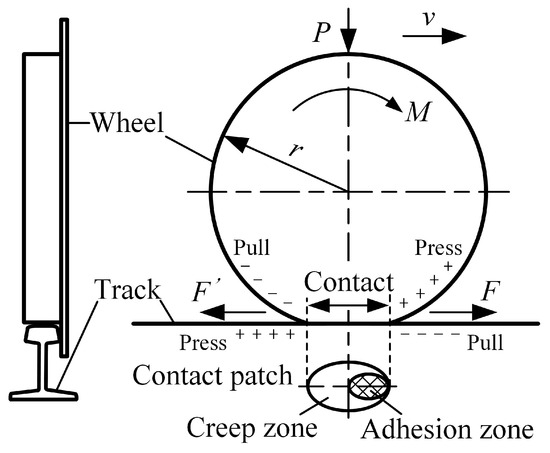
Figure 6.
Schematic diagram of adhesion between wheels and rails.
According to the International Union of Railways (UIC) definition of creep rate, the creep rate is represented as follows:
Based on the operating results when the friction between the wheel and rail is 0.3 (Figure 2), it can be observed that there is a sudden change in the interaction of wheel and rail during vehicle acceleration, and the creep rate value is abnormal.
2.4. Control Objectives
As the main auxiliary transportation tool in the coal mine roadway, the mining electric locomotive is greatly affected by the humid, muddy and other harsh environment during driving. When there are pedestrians or obstacles, the tram can’t bypass to avoid them, but only take emergency braking. Wet and slippery road surface may lead to insufficient wheel/rail adhesion of mining electric locomotive. When the vehicle is in traction condition and the traction force is greater than the wheel/rail adhesion, the wheel will idling. When the vehicle is in braking condition and the braking force is greater than the adhesion, the wheels will slip. The occurrence of these situation will cause the wheel tread and rail surface to be scratched, which will seriously affect the safety and stability of the vehicle. Therefore, the most critical control factor for the safe running of mining electric locomotive on the track is the value of the driving/braking torque applied on the axle. In this way, we can directly control the driving acceleration and speed of the vehicle by controlling the torque to avoid driving accidents such as vehicle braking failure and vehicle rollover.
As shown by the adhesion characteristic curves under dry and wet rail surface conditions in Figure 7, when the creep rate is within the range of −10% to 10%, the absolute value of the adhesion coefficient between the wheel and rail rapidly increases under braking/traction conditions [20]. When the creep rate is within the range of −30% to −10% and 10% to 30%, the absolute value of the adhesion coefficient between the wheel and rail reaches its optimal value under braking/traction conditions. When the creep rate is around ±20%, the wheel rail adhesion coefficient will reach its peak, and at this time, the vehicle can obtain maximum ground braking/traction force, which can minimize the braking distance. Therefore, controlling the creep rate within the range of ±10% to ±30% is an ideal control goal.
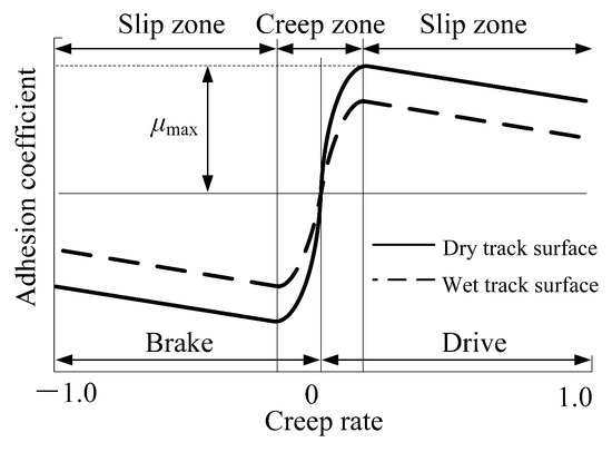
Figure 7.
The adhesion characteristic curves under dry and wet rail surface conditions.
3. Creep Controller Model
In this section, an RL speed control method for mining electric locomotives based on the optimal creep rate is proposed. For mining electric locomotives, there are many turns and narrow sections in coal mine roadway, and there are many emergencies during the operation of the locomotives. This method can fully utilize the advantage of RL that does not rely on models. The impact of complex mine environments on vehicle driving processes, especially the impact of slippery wheel/rail conditions that are difficult to quantify and evaluate on vehicle safety and autonomous operation, is converted into reward feedback obtained by vehicles from the environment. This method simplifies the modeling process of vehicle driving conditions and improves the efficiency of intelligent algorithm calculation. There are three major elements in RL, including state, reward, and strategy for selecting actions. When using RL method for creep control of the mining electric locomotive, the mining electric locomotive is considered as an intelligent agent, and the algorithm components are designed as follows.
3.1. State and Action
According to the starting or stopping of the mining electric locomotive, whether the driving section is a curve or a straight road, whether there are obstacles, whether the operating speed reaches the speed limit of the corresponding section, and whether the electric locomotive reaches the destination, the state of the RL creep control algorithm for the mine electric locomotive is set to 16 as shown in the Table 1. In addition, the torque applied on the axle has three forms: positive, negative, and zero, corresponding to the three actions of vehicle acceleration, deceleration, and uniform speed.

Table 1.
State Design of the Mining Electric Locomotive Autonomous Control Based on RL.
During the execution of the algorithm, the real-time position and speed of the mining electric locomotive are recorded every 0.01s to determine the changes of electric locomotive state during the sampling interval. At the same time, the algorithm will also timely provide the actions that should be applied within the sampling time of 0.01s, ensuring the timeliness of control.
It is worth pointing out that ’Technical Conditions for Explosion-proof Special Battery Electric Locomotives in Coal Mines’ (JB/T 4091-2014, published by Ministry of Industry and Information Technology of the People’s Republic of China in Jul. 2014) stipulates that mining electric locomotives should pass through the curve radius at a 50% of hourly speed. For the CTY1.5/6 electric locomotive used in this case, the maximum speed of the vehicle is 2.83 m/s (10.2 km/h), and the hourly speed of the vehicle is 1.80 m/s (6.5 km/h). Therefore, when the mining electric locomotive passes a curve with a radius of curvature greater than 4m, the minimum speed of the vehicle is 0.90 m/s.
3.2. Features of Reward Function
The appropriate definition of the reward function can directly determine whether the learning process of RL algorithms can efficiently and quickly achieve the desired training objectives. The main task of RL is to maximize rewards by selecting the best action at each sampling time. The ultimate goal of control algorithm for the electric locomotive is to achieve the optimal creep rate utilization in uncertain and harsh roadway environments, reduce the occurrence of slip and idling phenomena, and achieve the best operating efficiency under the premise of safe operation. Therefore, the reward function is directly related to the control effect of the mining electric locomotive’s driving speed and creep rate under different states.
Whether the mining electric locomotive has encountered obstacles or reached the maximum speed of the corresponding road section is classified during the state setting. When setting the reward function, whether the vehicle is accelerating, decelerating, or running at the uniform speed in the current state should be considered. The vehicle changing at a faster speed to achieve the desired control purpose will present a better training effect. The following speed reward conditions is defined based on repeated experiments. The main way to measure the size of the reward value is to calculate the speed change that occurs during the unit sampling interval for the vehicle to achieve control objectives.
where, represents the speed reward coefficient, which can be obtained through multiple experiments.
According to the control goal proposed in Section 2.4 of the paper to control the creep rate within the range of ±10% to ±30%, the creep control reward conditions are set. We have comprehensively considered the creep rate of four wheels, and the evaluation criteria for the creep rate reward are set as follows.
When the absolute values of the creep rate of the left front wheel , right front wheel , left rear wheel , and right rear wheel are all approximately equal to the optimal creep rate of 0.2 when taking two decimal places, the reward value can be set to:
In other cases, the reward value is set to:
where, and represent the reward coefficient for optimal creep rate and the reward coefficient for creep rate respectively, which can be obtained through multiple experiments.
We add the evaluation results of speed and creep with ratio of 1:1 to obtain the final reward function formula:
3.3. Structure of the Creep Control Method
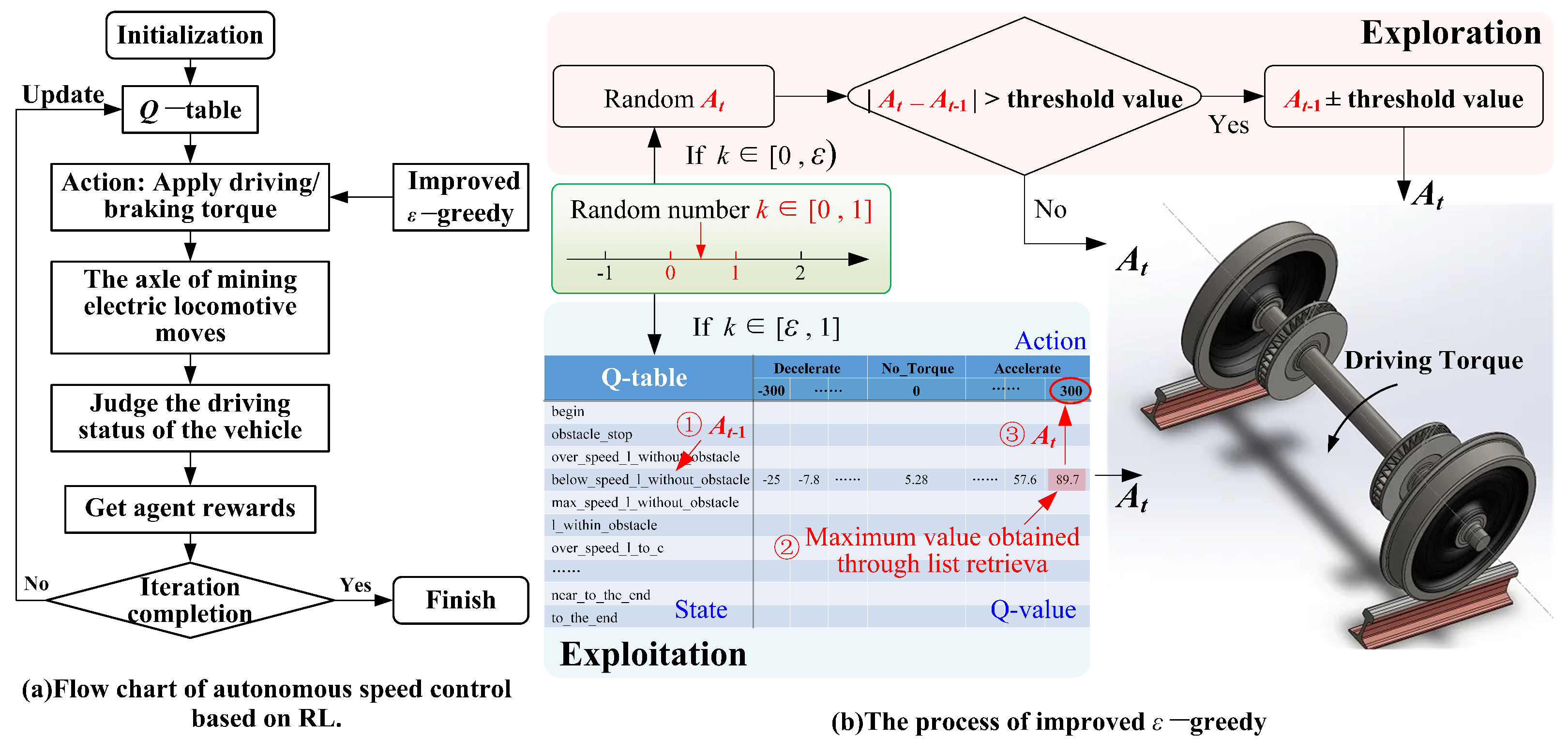
After setting up the intelligent agent, state, action, and reward function, a complete creep control framework for mining electric locomotives should be designed. As shown in the Figure 8, the mining electric locomotive serves as an intelligent agent to determine the current state based on the conditions of the environment at the current moment t. Then the intelligent agent uses an improved -greedy method to select the actions to be executed, obtain the current action , and apply it to the axle. Finally, the intelligent agent obtains the corresponding reward value based on the current environment and state. This reward is used to update Q-table.
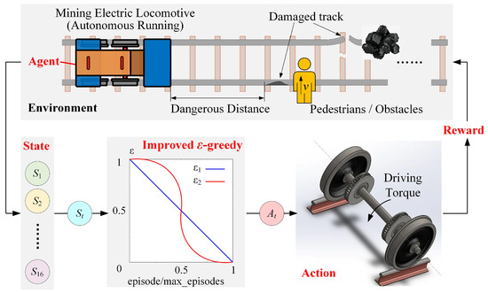
Figure 8.
Details of the CTY1.5/6 creep control method.
4. Simulation Verification and Results
In this section, we verify the proposed RL based creep control method for autonomous operation of mining electric locomotives through simulation experiments. A dynamic model of the CTY1.5/6 mining electric locomotive is built through Simpack. And the algorithm framework based on the Python language environment is designed. MATLAB is used as the intermediate carrier for connecting the algorithm and model, mainly responsible for the collection of dynamic model data and the output of algorithm operation results. Therefore, in this paper, the validation of the algorithm will be carried out through a co-simulation platform built by Simpack, MATLAB, and Python. The simulation platform is used to verify the effectiveness of the creep control method for autonomous operation of mining electric locomotives. The creep control method is compared with traditional -greedy algorithms to highlight the advantages of the improved -greedy algorithm in terms of learning efficiency.
4.1. Simulation Platform and Setup
The Windows 11 Professional 64 bit system is used as a simulation platform operating system, equipped with an Intel (R) Core (TM) i9-9900K CPU @ 3.60 GHz CPU and NVIDIA GeForce RTX 2070 SUPER GPU. The composition software of the co-simulation platform is PyCharm Community Edition, MATLAB R2014b and Simpack 2018.1. The language environment of Python 2.7 and its equipped third-party libraries such as Matlabengine for Python R2014b and Openpyxl 2.6.4 provide the foundation for the operation of simulation platform algorithms.
We use the RL algorithm based on the improved -greedy mentioned above to train the creep control of the CTY1.5/6 mining electric locomotive. The number of iterations is 500, with a maximum runtime of 45 s and a sampling interval of 0.01 s. The learning rate of this algorithm is set to 0.2, and the Q-learning discount rate is 0.8. The initial and final values of are set to 0.01 and 1, respectively. The driving section of the mining electric locomotive is composed of a combination of 20 m straight road-20 m curved road-20 m straight road. In general, the friction between the rail and the wheel is 0.2–0.4. Therefore, the friction coefficient on the track surface is set to 0.3.
4.2. Simulation Results
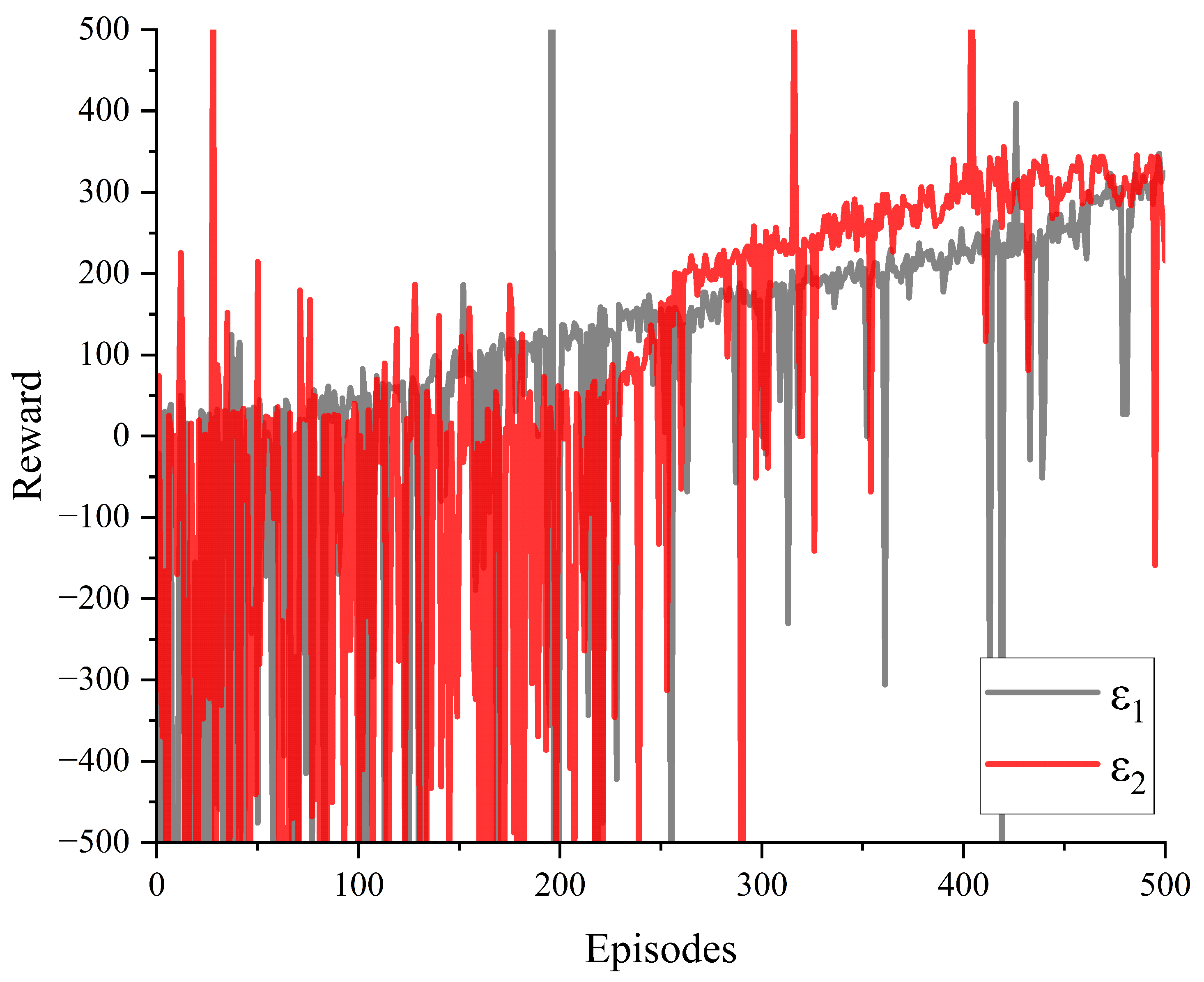
The reward values for creep control of the mining electric locomotive obtained through simulation using traditional -greedy and improved -greedy algorithms are shown in the Figure 9. It can be seen that under the condition of training 500 times, the agent obtains larger reward values in the first half of the training using traditional -greedy. The increasingly stable creep control reward value is obtained in the later stages of training during the use of improved -greedy algorithm for autonomous driving simulation in mining electric locomotives. This indicates that the improved -greedy algorithm we have designed can fully utilize the experience gained from exploration in the first half of the training, while the exploration of traditional -greedy in the first half of the training is clearly limited. And towards the end of the training stage, the reward value tends to stabilize to ensure the reliability of the training results, allowing the agent to repeatedly train and verify the optimal value.

Figure 9.
Results of reward with different values of .
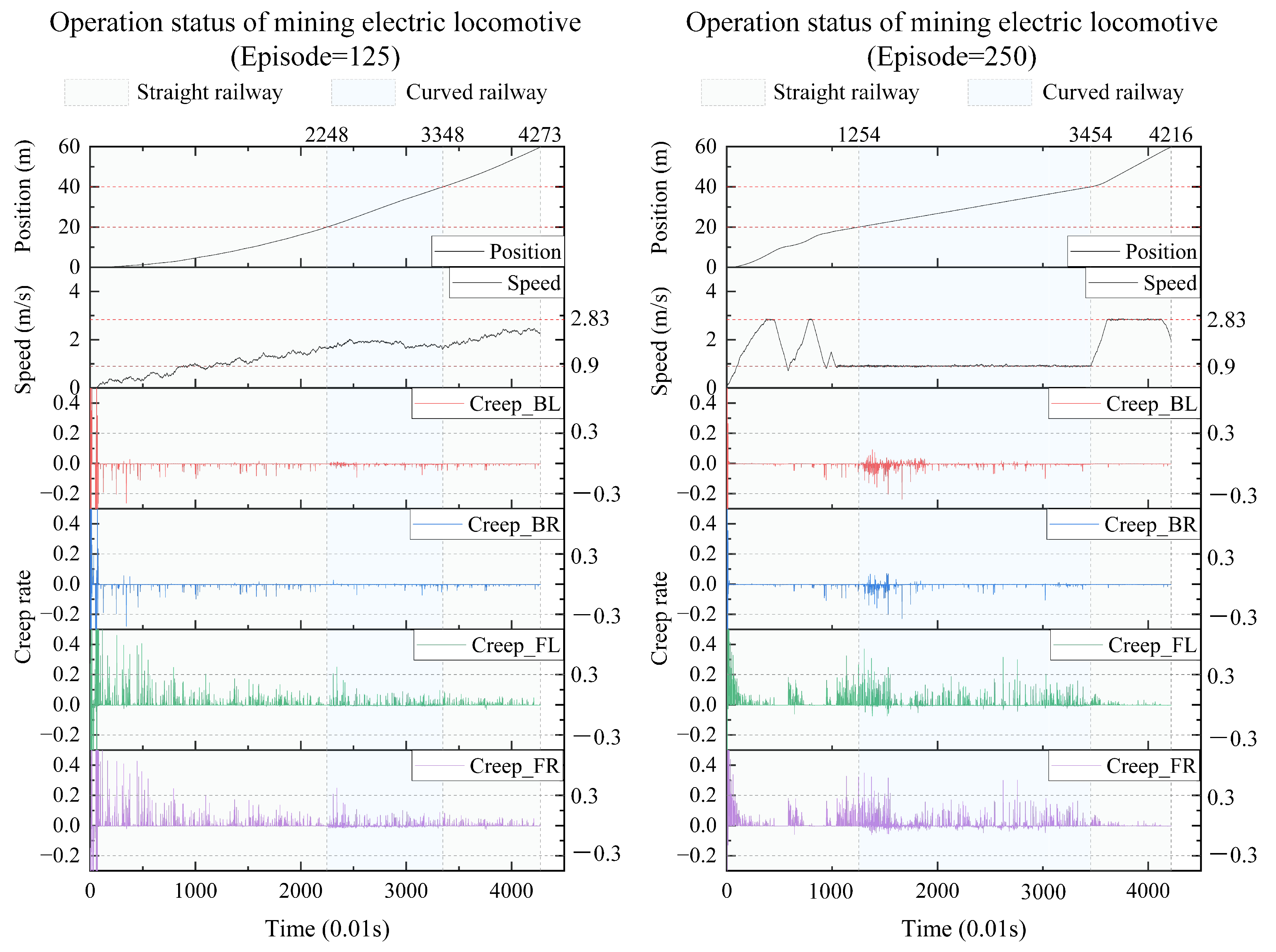
We take the results every 125 iterations and plot the real-time position, speed, and creep rate of each wheel of the mining electric locomotive. From the 125th iteration to the 500th iteration (Figure 10 and Figure 11), the mining electric locomotive can achieve their destination. However, the speed change is different. It can be easily observed that the mining electric locomotive cannot fully achieve the maximum speed limit for straight or curved roads during the initial training stage, and the vehicle cannot stop at its destination. As the training progresses, the mining electric locomotive acceleration increases.It can operate efficiently on speed limited sections, with accurate braking at the destination. On the first straight section of the road, the mining electric locomotive can maintain a safe distance when encountering obstacles.
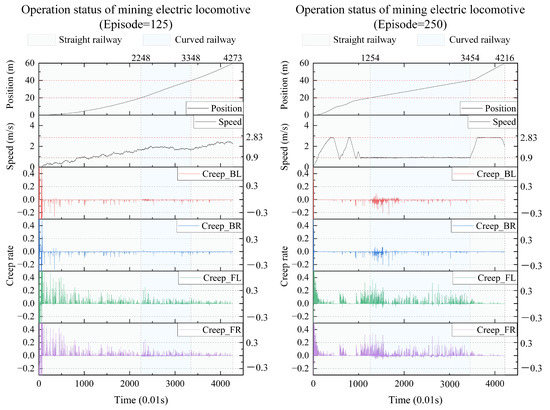
Figure 10.
The operating status of mining electric locomotives with episode = 125 and episode = 250.
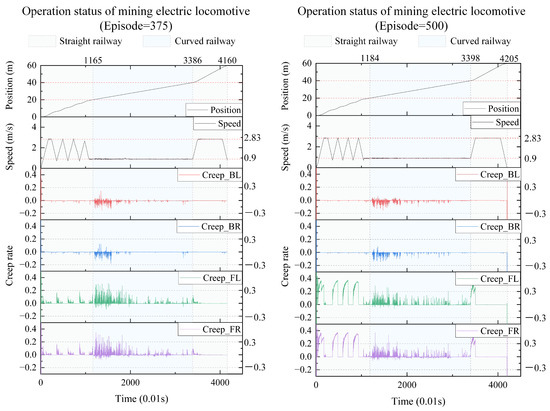
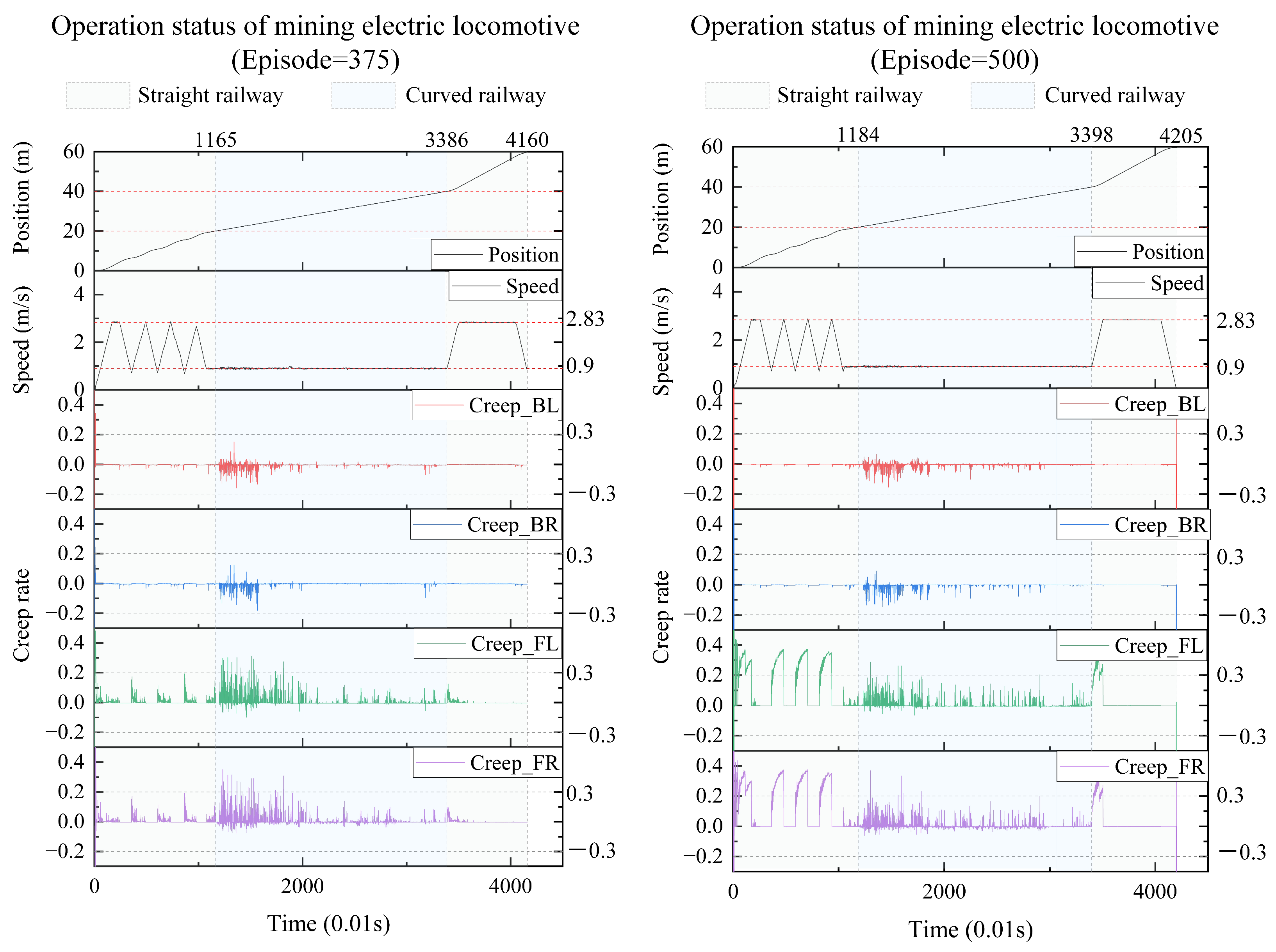
Figure 11.
The operating status of mining electric locomotives with episode = 375 and episode = 500.
In terms of controlling the creep rate, it can be seen that the creep rate fluctuates greatly during vehicle acceleration, which can easily lead to wheel spin. Meanwhile, when the vehicle is driving in a bend, there is also a fluctuation in creep rate, indicating the possibility of some wheels slipping at certain times during the turning process. After training the agent, it can be seen that as the number of iterations increases, the idle time during the vehicle acceleration process significantly decreases, almost eliminating the phenomenon of the vehicle slipping on curves. When the intelligent agent is trained 500 times, the creep rate of the vehicle during acceleration can be controlled within the range of 0.1 to 0.4. This indicates that the creep rate between the wheels and rails is well controlled during vehicle operation and is well utilized to drive wheel acceleration. This proves that the design of our learning algorithm is reasonable and effective, which can better utilize the creep rate and achieve the goal of safe and efficient creep control.
We also conduct simulation experiments on the driving results of an 8-ton electric locomotive in an 86 m tunnel with a friction coefficient of 0.2. The results are detailed in Appendix C. From the results in Appendix C, it can be concluded that this method can be applied to different mining electric locomotives traveling on different track conditions. This method has good universal applicability in the control of creep rate and obstacle avoidance of mining electric locomotives.
5. Conclusions
In order to reduce the occurrence of idling or slipping caused by wet track surface and improve vehicle safety when mining electric locomotive is driving, an improved -greedy of creep control strategy for mining electric locomotives based on RL algorithm is designed in this paper. By reproducing and proving the autonomous control method of mining electric locomotives based on improved -greedy, the analysis of the operating conditions of mining electric locomotives shows that creep rate is an important influencing factor on the operation of electric locomotives in wet and slippery tunnels. An RL based creep control method is proposed, which considers the efficiency of vehicle driving speed and the effectiveness of creep control in the algorithm design process. Finally, simulation verification is conducted based on a co-simulation platform that can simulate the dynamic process of mining electric locomotives underground. The results show that this method can achieve safe operation of mining electric locomotives in complex and ever-changing mine environments, including being able to drive with maximum efficiency on speed limited sections, follow at a safe distance, and reduce the occurrence of dangerous phenomena such as slipping and idling during vehicle driving.
In addition, coal mine tunnels have harsh environmental conditions such as small cross-sections, high pressure, and easy deformation. The coal mine tracks are slippery and muddy, with many turns, and the behavior of nearby personnel is complex. The road environment for coal mine electric locomotives is difficult to predict. Therefore, we use real-time perception of vehicle driving conditions instead of predictive analysis, which is limited by sensor accuracy. In the future, we plan to adopt a data-driven fusion analysis method based on multi-source sensor information to improve the real-time perception accuracy of mining electric locomotives.
We will also apply the control strategy proposed in this article to coal mines in the future, and further optimize and improve the algorithm based on on-site test results. We will import the training results of the algorithm, namely the generated Q-table, into the industrial control computer of the electric locomotive to guide the vehicle to operate autonomously underground in the coal mine. At the same time, the actual operation data of the electric locomotive will also be continuously updated to optimize the Q-table.
Author Contributions
Conceptualization, Y.L.; methodology, Y.L.; software, Y.L.; validation, Y.L.; formal analysis, Y.L.; investigation, Y.L.; resources, Y.L., Z.Z. and X.L.; data curation, Y.L.; writing—original draft preparation, Y.L.; writing—review and editing, Y.L. and X.L.; visualization, Y.L. and X.L.; supervision, Z.Z.; project administration, Z.Z.; funding acquisition, Z.Z. All authors have read and agreed to the published version of the manuscript.
Funding
This research was funded by NATIONAL KEY R&D PROGRAM of funder grant number 2020YFB1314100, CHINA.
Institutional Review Board Statement
Not applicable.
Informed Consent Statement
Not applicable.
Data Availability Statement
Data are contained within the article.
Conflicts of Interest
The authors declare no conflicts of interest.
Abbreviations
The following abbreviations are used in this manuscript:
| RL | Reinforcement Learning |
| MDP | Markov Decision Process |
| UIC | International Union of Railways |
Appendix A
Assumption A1.
Define H as the contraction operator, the following formula is easily obtained:
Assuming that the optimal value function is a fixed point of H, it means:
That is, remains at its original value after any multiplication with the H operator.
Lemma A1.
Theorem-Cauchy’s convergence Test: The necessary and sufficient condition for the convergence of a sequence is that for any positive number ε, there must be a positive integer N that satisfies the following equation under the condition of :
We refer to that satisfies this condition as a Cauchy sequence. So the theorem can be expressed as: the necessary and sufficient condition for the convergence of sequence is that the sequence is a Cauchy sequence.
Theorem A1.
In the Q-learning algorithm, can converge to when the agent accesses any action in any state multiple times.
Proof.
The convergence of the Q function is proved:
According to the Theorem-Cauchy’s convergence Test, any function can ultimately converge to when is the optimal function of . □
Appendix B
In order to evaluate the balance effect of exploration and exploitation, regret is defined to represent the average possible loss at each step:
where, represents the expected return value corresponding to the optimal action.
Total regret is defined to represent the total loss:
where, represents the gap between the value of the action and the optimal action, and represents the number of times that the action a has been selected. The goal of maximizing cumulative returns is actually equivalent to minimizing total regret, and an excellent algorithm is hoped to reduce the number of choices for actions with large gaps. For such an evaluation system, the most crucial issue is that the gap in practical problems is difficult to obtain, as is unknown and also needs to be estimated. However, this evaluation system can still have guiding significance for the evaluation of strategies. It is usually assumed that is a known constant value when discussing.
If the total regret increases linearly with the increase of iteration, it indicates that the probability of selecting each action in the algorithm does not change at each time interval. That is, the regret at each step does not change, and the information obtained from exploration is not better utilized. A strategy that can better balance exploration and exploitation should have a sublinear total regret. As the iteration progresses, the regret for each time interval gradually decreases, and the selection of algorithms will gradually abandon those that are likely to achieve lower returns.
Lai and Robbins has proven that for all total regrets that may become an optimal strategy, an asymptotic lower bound in the form of logarithmic growth is required [16,21,22]:
The strategy of -greedy strategy can ensure that all actions are sampled infinitely as the number of iterations increases. Thereby the convergence of is ensured. This means that the probability of selecting the optimal action can converge to greater than 1 - , which is close to certainty. However, the probability of selecting the optimal action is only approaching a value, and its effectiveness cannot be guaranteed in practice. Obviously, the probability of each choice of action by -greedy is more than . So the regret is more than , which is a linear total regret. However, although -greedy is not the optimal method in theory, Kuleshov and Precup [23] have demonstrated through extensive experimental data that -greedy can often achieve better results than some complex methods in practice.
Set , . We will write the value of in the improved -greedy as follows:
To demonstrate the convergence of the improved -greedy strategy, we calculate the regret of the strategy:
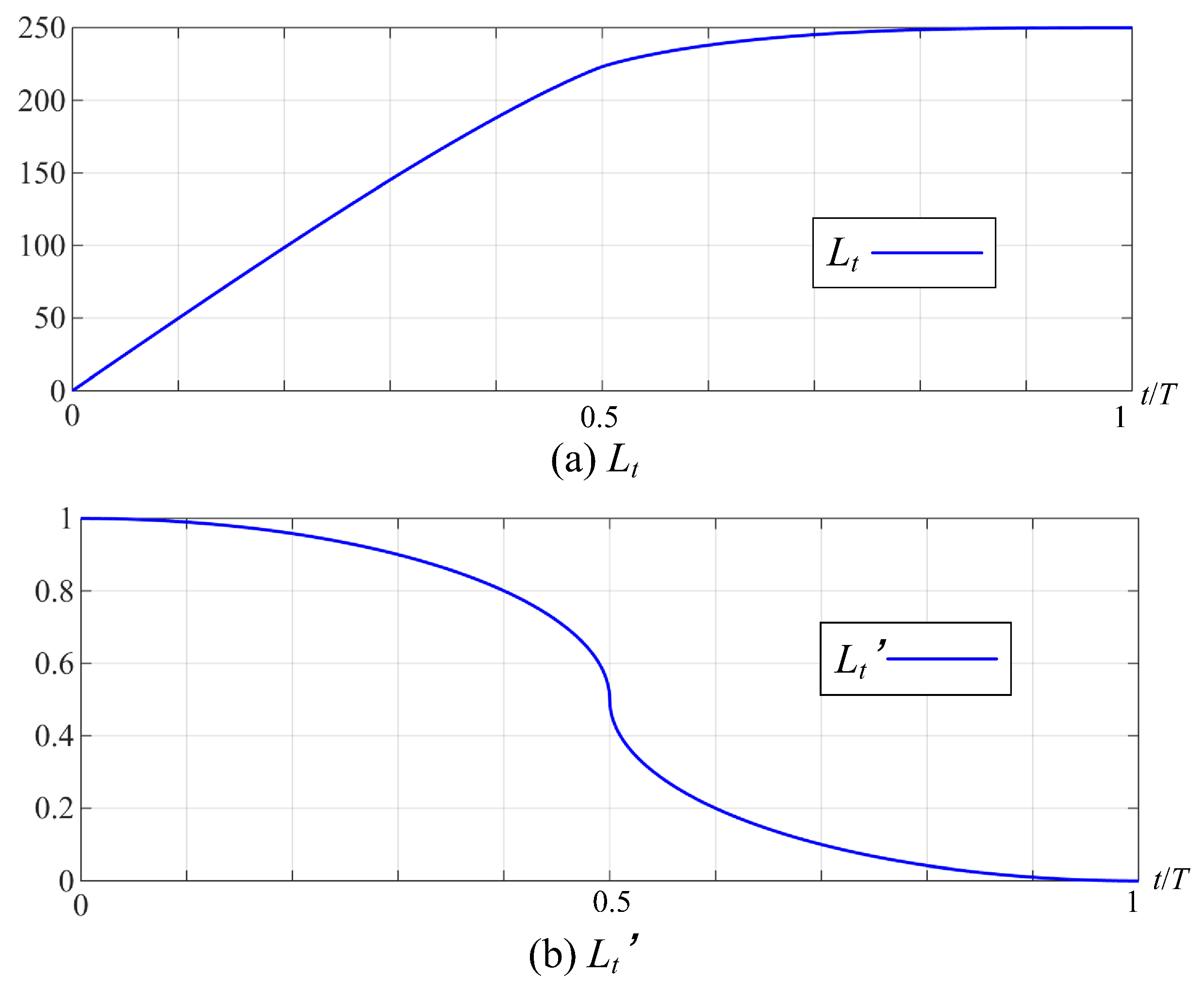
Plot the trends of and its derivative as the number of iterations increases. In Figure A1, it can be seen that is 0 in the later stage of iteration, and the value of no longer increases, indicating that the improved -greedy tends to converge.
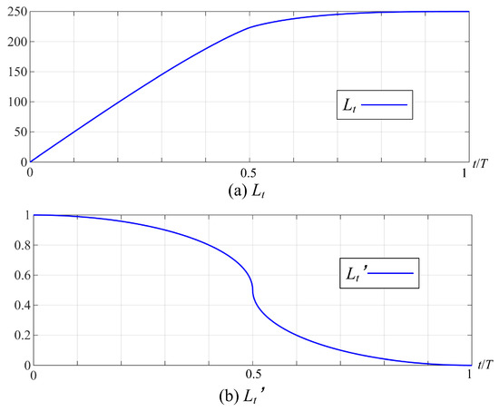
Figure A1.
The trend of total regret and its derivative .
Figure A1.
The trend of total regret and its derivative .
Appendix C

Figure A2.
The operating status of 8t mining electric locomotives with episode = 125 and episode = 250.
Figure A2.
The operating status of 8t mining electric locomotives with episode = 125 and episode = 250.
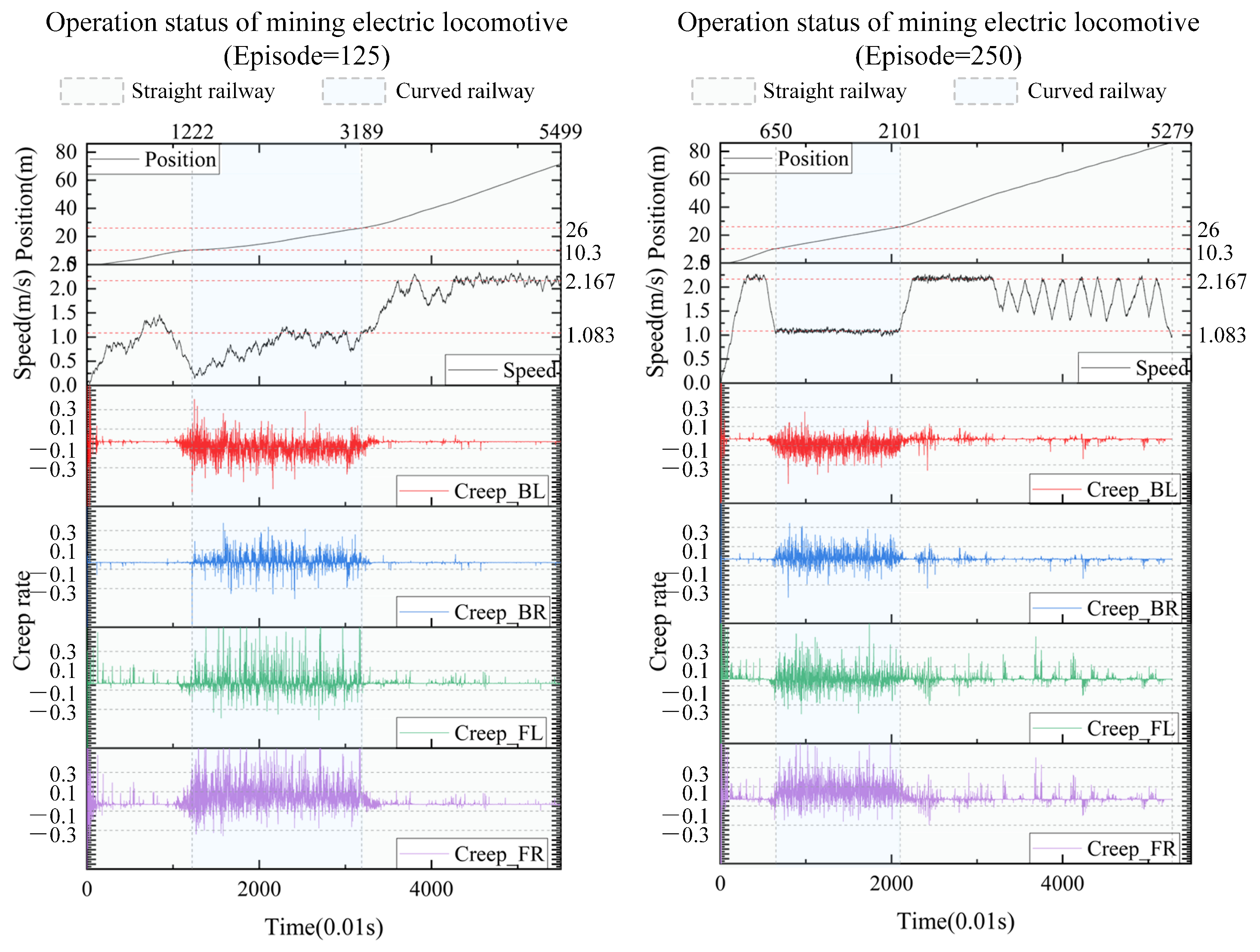
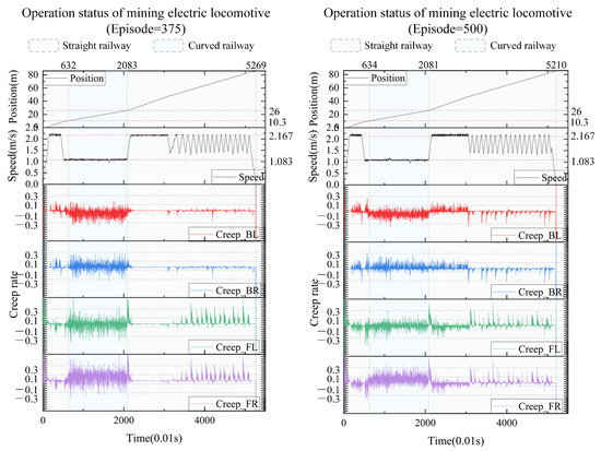
Figure A3.
The operating status of 8t mining electric locomotives with episode = 375 and episode = 500.
Figure A3.
The operating status of 8t mining electric locomotives with episode = 375 and episode = 500.
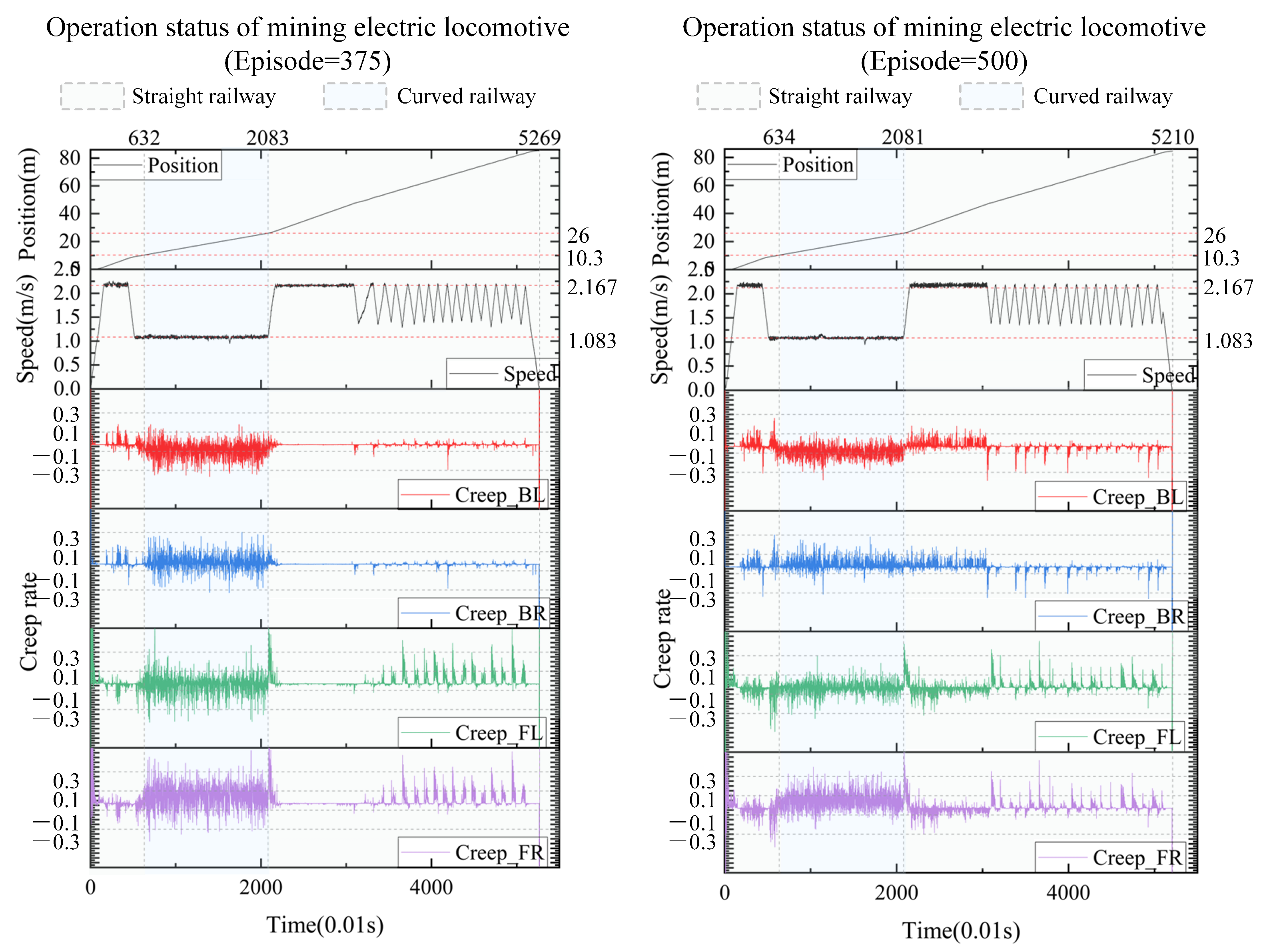
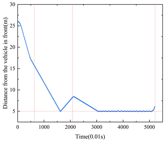
Figure A4.
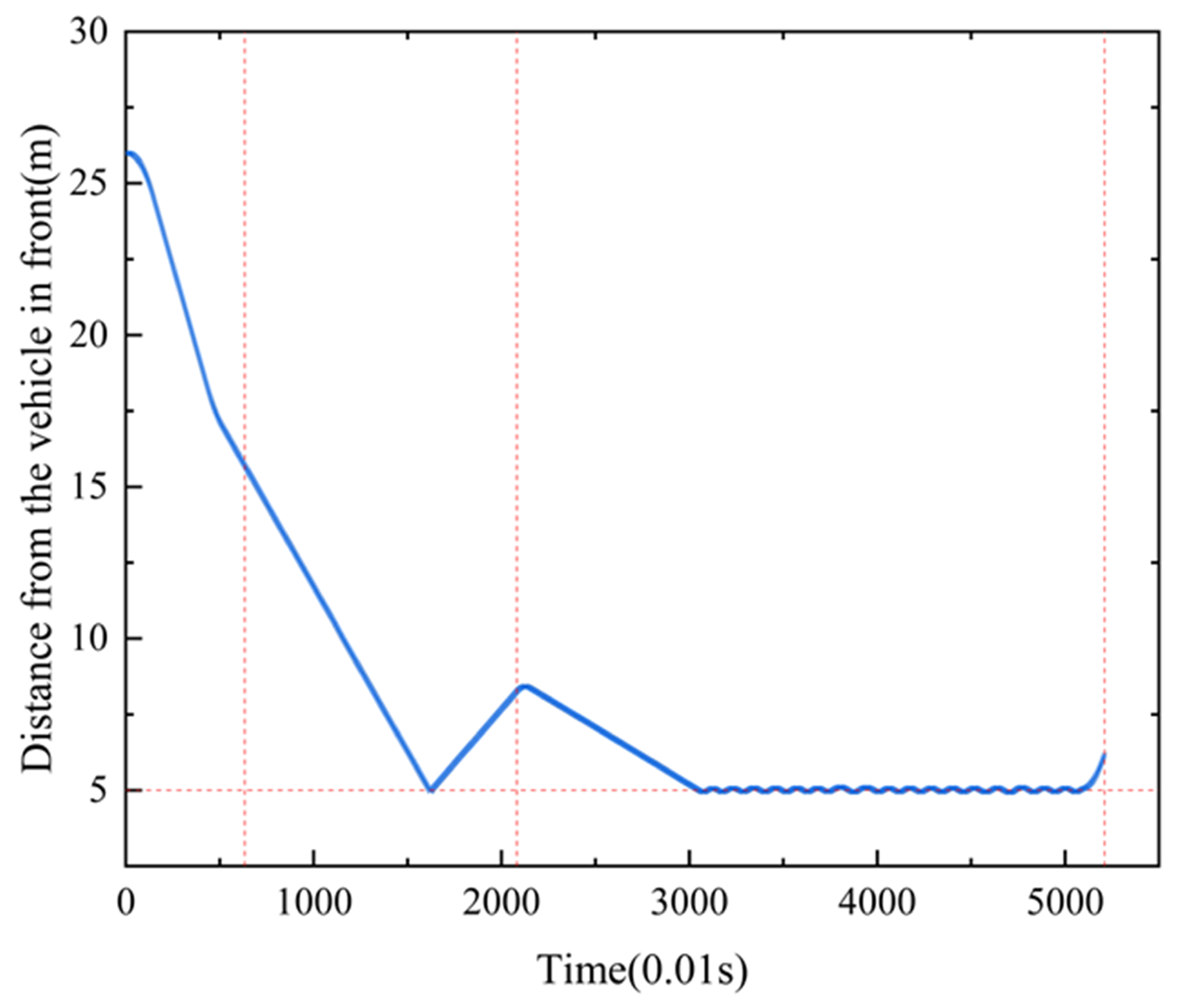
The distance from the vehicel in front of 8t mining electric locomotives.
Figure A4.
The distance from the vehicel in front of 8t mining electric locomotives.
In order to verify the universal applicability of the creep control based unmanned speed control method for mining electric locomotives proposed in this paper on different vehicles and road sections, we conduct simulation experiments on the autonomous operation of an 8-ton mining electric locomotive in this section. The hourly speed of the electric locomotive is 7.8 km/h (2.167 m/s). From the Figure A2 and Figure A3, it can be seen that the intelligent agent can control the creep rate within ±10%∼±30% during acceleration/deceleration sections. This indicates that our speed control method for autonomous operation of electric locomotives is effective in controlling creep rate.
In addition, to verify the effectiveness of this method in ensuring driving safety, we set the safety distance to 5 m when encountering obstacles or maintaining a safe distance from the preceding vehicle. From the Figure A4, it can be seen that the autonomous driving of the electric locomotive using this method is safe and effective, ensuring that the vehicle always maintains a distance of 5 m from obstacles or the preceding vehicle.
Therefore, this method can be applied to different vehicles traveling on different track conditions. This method has good universal applicability in the control of creep rate and obstacle avoidance of mining electric locomotives.
References
- Wang, G.F.; Liu, F.; Meng, X.J.; Fan, J.; Wu, Q.; Ren, H.; Pang, Y.; Xu, Y.; Zhao, G.; Zhang, D.; et al. Research and practice on intelligent coal mine construction (primary stage). Coal Sci. Technol. 2019, 47, 1–36. [Google Scholar]
- Ge, S.R. Present situation and development direction of coal mine robots. China Coal 2019, 45, 18–27. [Google Scholar]
- Li, Y.; Zhu, Z.C.; Li, X.Q.; Yang, C.Y.; Lu, H. When mining electric locomotives meet reinforcement learning. arXiv 2023, arXiv:2311.08153. [Google Scholar] [CrossRef]
- Fang, C.C.; Jaafar, S.A.; Zhou, W.; Yan, H.K.; Chen, J.; Meng, X.H. Wheel-rail contact and friction models: A review of recent advances. Proc. Inst. Mech. Eng. Part J. Rail Rapid Transit 2023, 237, 1245–1259. [Google Scholar] [CrossRef]
- Vollebregt, E.; Six, K.; Polach, O. Challenges and progress in the understanding and modelling of the wheel-rail creep forces. Veh. Syst. Dyn. 2021, 59, 1026–1068. [Google Scholar] [CrossRef]
- Zhao, Y.H.; He, X.; Zhou, D.H.; Pecht, M.G. Detection and Isolation of Wheelset Intermittent Over-Creeps for Electric Multiple Units Based on a Weighted Moving Average Technique. IEEE Trans. Intell. Transp. Syst. 2022, 23, 3392–3405. [Google Scholar] [CrossRef]
- Lu, C.X.; Chen, D.L.; Shi, J.; Li, Z.Q. Research on wheel-rail dynamic interaction of high-speed railway under low adhesion condition. Eng. Fail. Anal. 2024, 157. [Google Scholar] [CrossRef]
- Gao, X.; Lu, Y. Study of locomotive adhesion control. Railw. Locomot. Car 2017, 3, 35–39. [Google Scholar]
- Yamazaki, O.; Ohashi, S.; Fukasawa, S.; Kondo, K. The proposal of re-adhesion control method with the advantage of individual control system. In Proceedings of the International Conference on Electrical Systems for Aircraft, Railway, Ship Propulsion and Road Vehicles (ESARS), Aachen, Germany, 3–5 March 2015. [Google Scholar]
- Yamashita, M.; Soeda, T. Anti-slip re-adhesion control method for increasing the tractive force of locomotives through the early detection of wheel slip convergence. In Proceedings of the 17th European Conference on Power Electronics and Applications (EPE ECCE-Europe), Geneva, Switzerland, 8–10 September 2015. [Google Scholar]
- Wen, X.K.; Huang, J.C.; Zhang, S. Anti-slip re-adhesion control strategy of electric locomotive based on distributed MPC. In Proceedings of the 2019 IEEE 21st International Conference on High Performance Computing and Communications, Zhangjiajie, China, 10–12 August 2019. [Google Scholar]
- Çimen, M.A.; Ararat, Ö.; Söylemez, M.T. A new adaptive slip-slide control system for railway vehicles. Mech. Syst. Signal Process. 2018, 111, 265–284. [Google Scholar] [CrossRef]
- Wang, S.; Wang, X.G.; Huang, J.C.; Sun, P.F.; Wang, Q.Y. Adhesion Control of High Speed Train Based on Vehicle-control System. In Proceedings of the 2021 IEEE 16th Conference on Industrial Electronics and Applications (ICIEA), Chengdu, China, 1–4 August 2021. [Google Scholar]
- Zhang, S.; Huang, Z.W.; Yang, Y.Z.; Gao, K.; Zhu, C. A Safe and Reliable Anti-Lock Wheel Control with Enhanced Forgotten Factor for Brake Operation of Heavy Train. In Proceedings of the 2017 IEEE International Symposium on Parallel and Distributed Processing with Applications, Guangzhou, China, 12–15 December 2017. [Google Scholar]
- Martin-Guerrero, J.D.; Lamata, L. Reinforcement Learning and Physics. Appl. Sci. 2021, 11, 8589. [Google Scholar] [CrossRef]
- Kulkarni, S.R.; Lugosi, G. Finite-time lower bounds for the two-armed bandit problem. IEEE Trans. Autom. Control. 2000, 45, 711–714. [Google Scholar] [CrossRef]
- Malvezzi, M.; Pugi, L.; Papini, S.; Rindi, A.; Toni, P. Identification of a wheel-rail adhesion coefficient from experimental data during braking tests. Proc. Inst. Mech. Eng. Part J. Rail Rapid Transit 2013, 227, 128–139. [Google Scholar] [CrossRef]
- Polach, O. Creep forces in simulations of traction vehicles running on adhesion limit. Wear 2005, 258, 992–1000. [Google Scholar] [CrossRef]
- Fu, G.H. An extension of Hertz’s theory in contact mechanics. J. Appl. Mech. Trans. ASME 2007, 74, 373–374. [Google Scholar] [CrossRef]
- Polach, O. A fast wheel-rail forces calculation computer code. Veh. Syst. Dyn. 1999, 33, 728–739. [Google Scholar] [CrossRef]
- Tze, L.L.; Herbert, R. Asymptotically efficient adaptive allocation rules. Adv. Appl. Math. 1985, 6, 4–22. [Google Scholar]
- Auer, P.; Cesa-Bianchi, N.; Fischer, P. Finite-time analysis of the multiarmed bandit problem. Mach. Learn. 2002, 47, 235–256. [Google Scholar] [CrossRef]
- Volodymyr, K.; Doina, P. Algorithms for multi-armed bandit problems. arXiv 2014, arXiv:1042.6028. [Google Scholar]


Disclaimer/Publisher’s Note: The statements, opinions and data contained in all publications are solely those of the individual author(s) and contributor(s) and not of MDPI and/or the editor(s). MDPI and/or the editor(s) disclaim responsibility for any injury to people or property resulting from any ideas, methods, instructions or products referred to in the content. |
© 2024 by the authors. Licensee MDPI, Basel, Switzerland. This article is an open access article distributed under the terms and conditions of the Creative Commons Attribution (CC BY) license (https://creativecommons.org/licenses/by/4.0/).