Article

A 3UPS/S Spherical Parallel Manipulator Designed for Robot-Assisted Hand Rehabilitation after Stroke

by
Tony Punnoose Valayil
* and
Tanio K. Tanev
Institute of Robotics, Bulgarian Academy of Sciences, 1113 Sofia, Bulgaria
*
Author to whom correspondence should be addressed.
Appl. Sci. 2024, 14(11), 4457; https://doi.org/10.3390/app14114457
Submission received: 15 April 2024 / Revised: 11 May 2024 / Accepted: 17 May 2024 / Published: 23 May 2024
(This article belongs to the Section Applied Biosciences and Bioengineering)

Abstract

:
Hand dysfunction is a common symptom in stroke patients. This paper presents a robotic device which assists the rehabilitation process in order to reduce the need of physical therapy, i.e., a 3UPS/S parallel robotic device is employed for repetitive robot-assisted rehabilitation. Euler angle representation was used to solve the robot’s inverse kinematics. The robot’s joint space and rotational workspace were determined for two scenarios. In the first scenario, the workspace was obtained considering the actuator’s stroke limitations, while in the second scenario, the workspace was determined by adding a second condition, i.e., the range of motion of the spherical joints. Singularity analysis was performed using the geometric algebra approach. The robot was manufactured using additive manufacturing technology. The solution of the inverse kinematic problem was employed to control the robot. The robot can perform a full range of motion during wrist ulnar deviation and radial deviation motions, with the exception of limited wrist flexion and extension motions. The robot has singular configurations within its workspace. Although the spherical joints have roles in reducing the workspace, the primary causes are actuator selection, radii of the base and moving platforms, and the length of the central leg. These factors can be considered to improve the workspace. Singularity can be avoided by carefully selecting the rotation of the moving platform about the Z-axis and avoiding same leg lengths.

1. Introduction

According to the World Stroke Organization (WSO): Global Stroke Fact Sheet 2022, stroke continues to be the world’s second greatest cause of death and the third leading cause of combined death plus disability worldwide. People under the age of 70 account for more than 62% of all stroke cases each year. Thus, stroke is no longer only an illness of older people. One of the most prevalent symptoms of stroke is the hand dysfunction, which affects approximately 80% of the stroke patients [1].
One of the primary goals of stroke rehabilitation is the hand function rehabilitation since hand dysfunction has a detrimental effect on a patient’s psychological well-being and severely impairs the quality of life for patients and their relatives. Fortunately, with rigorous and consistent rehabilitation activities, the human motor system can recover from an injury and resume its function. Because the central nervous system is plastic, stroke patients can benefit from repetitive rehabilitation, which will help their limbs to form new connections with the central nervous system. A successful rehabilitation program is essential for treating stroke patients. Currently, repetitive rehabilitation is employed in rehabilitation activities to assist, rebuild, and restore tissues and nerves. Robot-assisted rehabilitation has been developed in response to the need for a more logical and scientific approach to satisfy patients rehabilitation demands in addition to traditional approaches [2].
The application of robots has been extensively utilized in major fields of science and innovative industry. In particular, the field of medical applications has seen numerous innovations in providing solutions to bridge the gap between human intervention and the availability of resources. This has spurred research interests in segments such as treatments and therapy.
Rehabilitation therapy is one of the major treatment techniques for stroke patients. The survivors of stroke experience paralysis or loss of physical strength on one side of the body, making it difficult to perform their day-to-day activities. Rehabilitation is that process which allows them to relearn the best possible use of their limbs and regain independence. Rehabilitation therapies are carried out at specific health centres or hospitals with highly skilled/qualified physiotherapists. The therapy is effective only when it is administered soon after stroke. This is not always possible due to its labour-intensive nature. Rehabilitation is repetitive and routine physical exercise which is performed with the help of a physiotherapist. Considering the alarming increase in the number of patients affected by strokes and the deficiency of qualified physiotherapists, the current state-of-the-art technology used in rehabilitating these patients and the need for robots which can substitute the human intervention during the training process are found to be skyrocketing. The current research around the globe in this discipline is developing exoskeleton manipulators that are reprogrammable and multifunctional, having an autonomous intelligent system that requires minimal intervention from therapists. The exoskeleton robots can be used as a solution for such conventional manual therapies.
The exoskeleton robots provide intensive rehabilitation consistently for a longer duration irrespective of the skills and fatigue level of the therapist. This exoskeleton robot has a similar kinematic structure to a human upper limb and is designed to operate alongside the limb. The exoskeleton robots are mechanical manipulators designed to be worn by humans. The current research around the globe in this discipline focuses on the development of exoskeleton manipulators that are reprogrammable and multifunctional, having an autonomous intelligent system that requires minimal therapist intervention. This powered exoskeleton is used to improve the muscle strength of paralyzed patients. Low-cost, efficient, and automated rehabilitation equipment can provide opportunities to establish micro or mini rehabilitation centres at both primary and secondary health centres, whereby the patients would not have the need to travel to district hospitals, state headquarters, or other specialized training centres for their treatment. The treatment can reach a larger pool of patients through these primary and secondary health centres. A training system with minimal or zero therapist intervention that is user-friendly can help to improve a patient’s recovery in good time and thereby increase their will for living a normal life again.
According to the structural topologies of robots, they can be classified as a serial manipulator (SM), parallel manipulator (PM), and hybrid manipulator. The precision, stiffness, payload capacity, and inertia of PMs are better in comparison to SMs [3]. Because of these inherent benefits, PMs have found widespread use in precision manufacturing, flight simulators, medical applications, pointing devices, and, more recently, video games [4]. The medical field has greatly benefited from the use of parallel robots, which have found use in humanoids, assistance, and rehabilitation. Future prospects show that parallel robots may become a market mainstay due to ongoing technical advancements and cooperation between the scientific community, business, and healthcare experts [5].
The number of degrees of freedom (DOFs) and the number of legs of the PM are typically equal. Occasionally, a six DOF PM is referred to as a hexapod rather than a Gough–Stewart platform. In the same way, a tripod refers to a PM with three legs. Pure translational motions are of interest for industrial applications and are a replacement of the serial manipulators. Numerous new designs of parallel robots with limited DOF have been found recently. Among these is the Delta robot, which has drawn particular interest from researchers because many technical applications only require three DOFs [6].

2. Related Work

PMs known as parallel wrists (PWs) only move spherically around a fixed point when there is a relative motion between the base and moving platforms [7]. Three-DOF spherical parallel manipulators (SPMs) have received a careful examination in the literature cited in this paper. For a considerable amount of time, only two manipulator architectures have been employed to obtain PWs. These are known as not-over-constrained and over-constrained PWs. The base and moving platforms of the over-constrained PWs are joined by three legs of type RRR (R stands for revolute pair), each of which has its axes intersecting at a fixed point. Geometric errors cause mechanism jams or excessive internal loads in the links of an over-constrained architecture [8].
Two categories of manipulators exist in PWs that are not over-constrained. The first group consists of 3UPU PMs (U and P stand for universal joint and prismatic pair), and the second set contains 3-SPS-1-S PMs, where S stands for spherical pair. Three legs of type SPS control the moving platform in 3-SPS-1-S PWs. To carry out the necessary orientation, the prismatic pairs are active ones. Only rotational motion is ensured by the fixed central leg with the spherical pair connecting the base platform and moving platform, which also makes the robot more rigid. This PW has three DOFs and a smaller workspace because of the passive spherical pair [9]. Systems for defence and surveillance employ the 3SPS-1S PM. A test scenario showcasing the robot’s use as a sentry gun was presented in [9]. The robot works well in the test scenario; however, to put this robot into use, a system that recognizes the intruder and plans the trajectory is required.
Karouia et al. [6] demonstrated that it is possible to achieve infinitesimal spherical motions using 3-UPU translational manipulators under specific manufacturing and mounting scenarios. It was therefore referred to as a 3-UPU wrist. Because the 3-UPU wrists overcome the limitations of two PWs (3-SPS-1-S and RRR) and do not require a passive spherical pair, they are of particular interest to researchers. While it is desirable to be able to perform an infinitesimal spherical motion, this requirement alone does not guarantee that the platform performs a finite spherical motion, i.e., a PW manipulator. Their research was therefore only useful in identifying potential PW architecture. The latter decade of the 20th century saw the discovery of these robots. Although these architectures are not used in commercial robots, researchers find them to be quite interesting. These designs could be reconfigured as PWs, translational PMs, or metamorphic PMs.
A 3UPU PW was created to follow the path of the sun. The fact that the fixed point on the heliostat is not precisely at the correct distance from the base, suggesting that the manufactured 3-UPU is not a perfect PW, is one of the main problems with sun tracking experiments. The ideal 3-UPU wrist has only three rotational DOFs. However, because of manufacturing flaws that cause the fixed point to become misaligned, the 3UPU moves in both position and orientation, making control more challenging with its existing controller. A greater manufacturing tolerance level needs to be maintained in order to remove pointing errors [4]. Commercial robots do not exist because, as the literature shows, all PW manipulators are unable to achieve the appropriate platform orientations.
Researchers have also used a combination of 3UPU PW and 3SPS/1S PW like the 3UPS/S, 3-UPS/RPU, and 3-PUS/S PMs in specific applications. For better design and control of a robot, solving kinematics is the foremost task [3]. Staicu [10] established a recursive relation between dynamics and kinematics for a 3-UPS/S manipulator. Inverse kinematics was solved using the recursive matrix method, and then using the principle of virtual work, inverse dynamics was solved. Wang et al. [11] solved the inverse kinematics using the matrix variation method. Then, forward kinematics was solved using the numerical analysis method.
Li et al. [12] built the virtual prototype for a 3-UPS/S parallel mechanism in ADAMS. It was used as an assistive exoskeleton for a human hip joint. It performed human hip movements (flexion/extension, adduction/abduction, and external/internal rotation). The forward kinematic analysis was solved and verified by building a parametric model in MATLAB. Han et al. [13] designed and fabricated a prototype of 3-UPS/S robot as a parallel airborne stabilized platform. Their research findings made it possible to conclude that for successive forward kinematic analysis, the Finite-Step-Integration method has good arithmetic accuracy and speed. Using this method, it was demonstrated that the aerial stabilized platform workspace is sufficient and the method was also quick and accurate in motion tracking.
Navarro et al. [14] designed a 3UPS1S for laparoscopic applications. The prototype was designed to cover the necessary workspace needed for this type of surgical technique. The device permits the positioning of a MIRS (Robotized Minimal Invasive Surgery) surgical instrument. Screw theory was used for kinematic analysis. Araujo-Gómez et al. [15] used a 3-UPS/RPU architecture for knee diagnosis and rehabilitation. Applying the inverse kinematic model, the leg motion of the robot was studied, and then using the leg motion through the simulation of the workspace of the robot, it was shown that the robot end-effector was able to follow a prescribed task. Tian et al. [16] used 3-UPS/S as a shipborne stable platform to compensate ship orientation fluctuation and isolated the influence of wind and waves on shipborne equipment. Hence, an efficient and accurate control strategy was developed for this purpose in their study.
Khoshnoodi et al. [17] proposed a 3-PUS/S SPM with three rotational motions. Furthermore, the application-specific study of its kinematic equations, singularity, and design optimization was conducted. The three legs of the proposed parallel robot, each with three prismatic joints, allow for an infinite rotation around the Z-axis. Because of this, the robot has huge workspace and good versatility. Using the Jacobian matrix, the singularity of the robot was found. Then, the optimum dimensions of the manipulator were studied by the Genetic Algorithm (GA), and the Global Condition Index (GCI) was maximized.
When encountering parallel singularities, PMs may sustain significant damage because the actuator forces needed to maintain the platform’s trajectory may approach infinity. It is crucial to determine whether a singularity-free path may lead to a desirable pose of the platform in the workspace and, if so, which path should be taken in the first instance. It is therefore very important to avoid singularity in PMs [18]. A numerical method developed by Paganelli [18] was able to find a path connecting any two points in the workspace that is devoid of singularities. This method can be applied to all 3UPS and 3UPU manipulators which do not possess degenerate non-singular critical points of the Jacobian determinant. Enferadi [19] determined the assembly modes of the 3UPS-S manipulator by modelling the forward displacement analysis using Rodrigues’ formula. By choosing one of the assembly modes as a home posture, the suggested strategy made it simple to prevent singularity configuration.
Li et al. [20] demonstrated that, with regard to singularity, the velocity analysis and mechanical analysis were consistent for the 3UPS/S parallel machine. They also demonstrated that, as the manipulator approaches singularity, the accuracy and actuator force attributes declined. Bonev et al. [21] showed that the Tilt-and-Torsion angles were a powerful geometric tool for the analysis of Type 2 singularities in 3-UPS/S manipulators. They also derived the workspace boundaries (Type 1 singularity loci) using this method [22]. The geometric relationship between the singular configuration of the 3UPS-S parallel mechanism and its single kinematic screw was explained and made clearer in a study by Han et al. [23]. The singular kinematic screw was derived by using the reciprocal product notion in screw theory when the manipulator is in singularity. The singular configurations are determined to be a part of the singular linear complexes.
There are several other parallel manipulators (PMs) and serial manipulators (SMs) employed for performing rehabilitation therapy. Some of them are discussed in Table 1. In these devices, the power is transmitted by a linkage mechanism (LM), gear drive (GD), or cable drive (CD). These devices use an electric motor (EM), pneumatic actuator (PA), or hydraulic actuator (HA) as actuators and perform basic movements such as flexion/extension (F/E), adduction/abduction (AD/AB), internal/external rotation (I/E), pronation/supination (P/S), and ulnar deviation/radial deviation (UD/RD) motions for shoulder (SR), elbow (EW), and wrist (WT) joints. These devices can also perform additional movements other than the above-mentioned basic movements and therefore have additional DOFs.
In recent years, many exoskeleton robots have been developed for upper limb rehabilitation and researchers have reviewed all of them, but focus has not been given to the mechanical design of active exoskeleton robots performing passive therapy. Active robots are those robots which are powered using an external source such as an electric motor. They can be used for performing passive therapy, a therapy where human effort is not needed. Hence, in Table 1, the proposed robot is compared with existing active robots which perform passive therapy in stroke patients. The comparison is based on the active degree of freedom (DOF), kinematic structure, power transmission method, type of actuator used, and rehabilitation applied on selected joints and supported movements.
From Table 1, the following can be concluded: The contemporary mechanical designs, especially the kinematic structure of upper limb exoskeleton robots, have unique features and are manifested in the fact that almost all of them are based on serial manipulators (SMs), and only a few others use parallel manipulators (PMs). Almost all exoskeleton robots employ electric motors or pneumatic actuators. The majority of the robots have less than seven DOFs.
Comparing the proposed exoskeleton robot with the existing devices in Table 1, it can be seen that the proposed system has only three DOFs. It can be used only for rehabilitating the wrist joint. Other devices perform additional movements for elbow and shoulder joints. The proposed exoskeleton robot has a parallel kinematic structure. Parallel manipulators are rarely used for wrist joint rehabilitation, whereas serial manipulators are mostly used. In this device, the power is transmitted using a linkage mechanism. The mechanical linkage is more reliable, very long-lived, and inexpensive compared to gear drives and chain drives. The proposed exoskeleton robot device uses an electric motor to perform basic wrist movements such as flexion/extension and ulnar deviation/radial deviation. The electric motors have advantages over the pneumatic and hydraulic actuators such as low maintenance cost, low operating cost, and high efficiency.
In 2022, Liu et al. conducted a thorough review [2] with an emphasis on mobile hand rehabilitation robots, encompassing both end-effector and exoskeleton models. Exoskeleton-style devices are ones whose joints match the patient’s anatomical joints. This allows for direct control over specific joints, lowering the possibility of unnatural postures. An end-effector-style device applies force to the farthest portion of the finger, enabling a straightforward initial setup at the expense of restricted control over the proximal finger joint. Twelve exoskeleton hand rehabilitation robots have been identified. Almost all of them use motor drives as driving modes except one device which uses series-elastic actuators. The device with series-elastic actuators employs force control as a control strategy. One of the devices uses EMG and all others use a preset control strategy. The robot–patient interaction control approach can be broadly classified into two types based on the signal utilized to determine the active movement intention: (i) control methods based on biomedical signals and (ii) control methods based on force signals. Seven of these devices use the link for force transmission mode, while two devices use a cable and link combination, and remaining use either cable and chain, spring and link, or rope and connecting rod combinations.
Then, in 2023, Abraca et al. [5] presented a systematic review on parallel robots used in the fields of assistive technologies, humanoids, and rehabilitation robots. Robots for rehabilitation are applied to help people who have been injured or ill to regain their strength, functionality, and motor skills. The purpose of assistive robots is to assist people in carrying out daily tasks. Robots called “humanoid” are a remarkable technological development. They resemble and reproduce human anatomy and behaviour. An updated summary of the field’s developments from 2012 to 2023 was provided by this systematic review. Thirteen publications in this cohort dealt with the neck joint, nine with the hip joint, twenty-two with the wrist joint, nine with the shoulder joint, and thirty with the ankle joint. Eight devices have been designed and developed for wrist rehabilitation in Australia, China, USA, and Japan. Five devices are at level TRL 3 and three devices are at TRL 4. Technology maturity is measured as a technology moves through the phases of research, development, and deployment using technology readiness levels, or TRLs. TRLs are rated from 1 to 9, where the most advanced technology is denoted by level 9. The technical maturity is estimated from conceptual models in their early stages (TRL 1) to fully functional systems (TRL 9). With the highest percentage of robots, TRL 3 suggests that a substantial amount of research has advanced to the proof-of-concept and prototype-building phases. TRL 4 indicates continued improvements in parallel robot systems, which could lead to a more practical application of these systems in rehabilitation environments. The devices use 3-RPS, 2-URR/RRS, 3-RRR, 6-SPS/PS, 3-RPR, cable-driven, and two 4-BMA (four biomimetic actuators) mechanisms. The 3-RPS mechanism has two DOFs and all remaining mechanisms have three DOFs. The 3-RPS and 2-URR/RRS mechanisms perform flexion/extension and adduction/abduction motions only, whereas all other mechanisms perform pronation/supination motions additionally. These devices use either linear electric actuators or pneumatic linear actuators. Five of these devices are modelled using inverse kinematics and the remaining three are modelled using both forward and inverse kinematics.
Challenges in the existing devices are the following:
  • All existing devices can be used for only one of the upper limbs (right or left limb).
  • All devices are attached to the limb. The user is not free from wearing it.
  • The weight of the device acts on the limb.
  • The devices do not perform any prescribed exercises suggested by clinicians.
  • The devices do not perform rehabilitation for all the fingers simultaneously.
  • The cost of the device is very high.
  • The users (stroke patients) cannot set up the device by themselves.
  • The existing devices cannot be used for all age groups (including children).
  • Additive manufacturing technology is not adopted. It saves time for manufacturing.
  • There is no single device which performs rehabilitation for the fingers, wrist, elbow, and shoulder joints together.
  • The majority of the devices are serial manipulators.
  • Most devices use linkage mechanisms, which are rigid links, and do not use complaint mechanisms.
  • Most devices use electric motors for actuation and do not use flexible actuators.
  • Existing devices do not perform wrist joint motions and finger motions together.
In this context, a 3UPS/S robot which can be set up to function as an SPM for wrist rehabilitation by executing three rotational DOFs is introduced. The exoskeleton and its parts are depicted in Figure 1. The 3UPS/S mechanism is suitable for executing the required movements in the rehabilitation process. The 3UPS/S exoskeleton robot has three rotational DOFs according to Grubler–Kutzbach criterion. The human wrist joint has two rotational DOFs. Therefore, the 3UPS/S exoskeleton robot can be used to rotate the wrist joint about two axes (roll and pitch), thereby performing wrist motions such as flexion/extension and ulnar deviation/radial deviation. Using the 3UPS/S parallel mechanism leads to the lightweight design of the exoskeleton robot with high stiffness.
The exoskeleton robot, presented in this paper, has many features/uniqueness when compared to other existing systems. Some of them are discussed below.
  • This exoskeleton robot is unique since it is one of the first to use a parallel wrist manipulator for upper limb rehabilitation. Given that the wrist joint has two rotational degrees of freedom, the proposed device can be used to rehabilitate the wrist after a stroke.
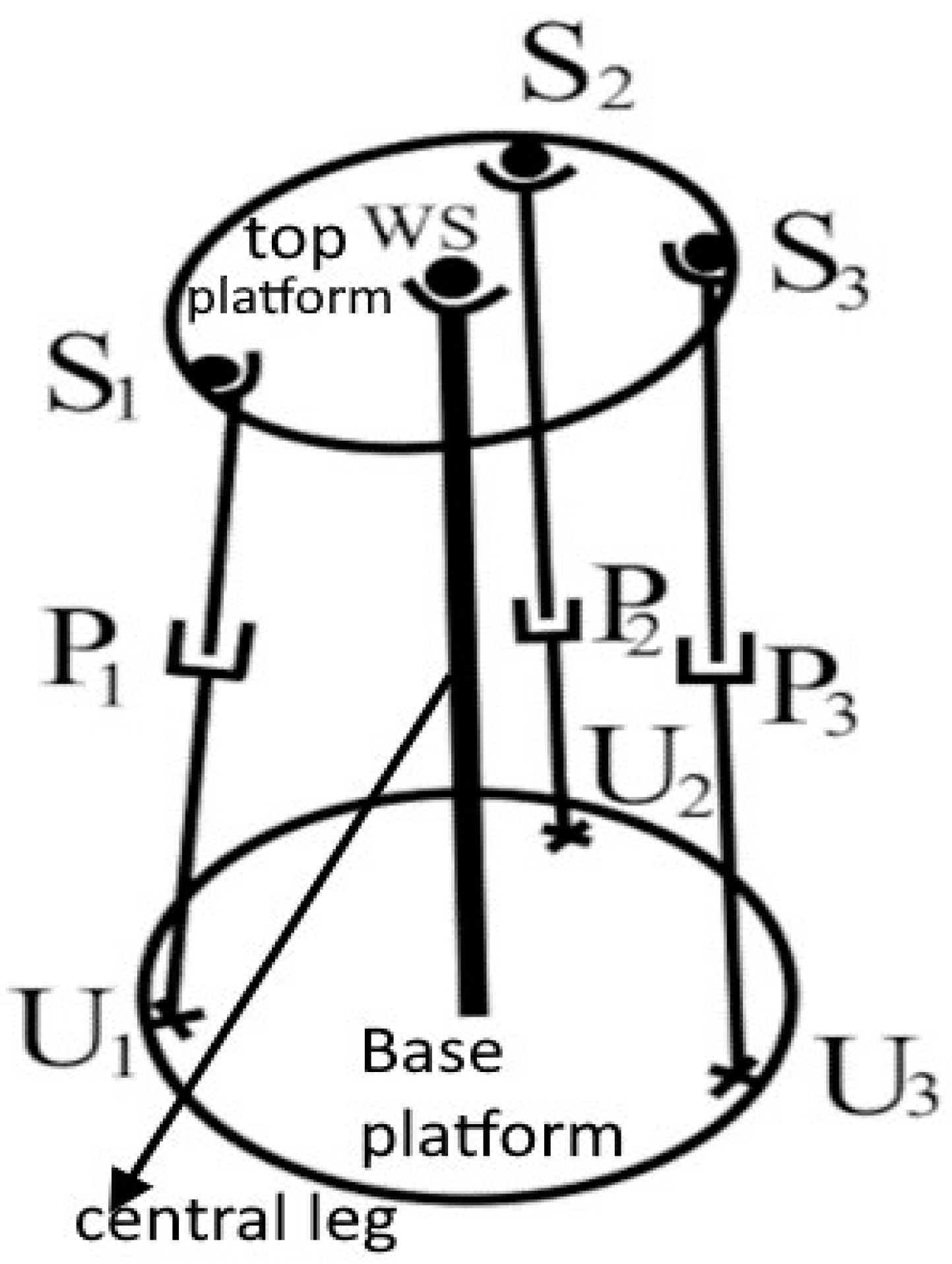
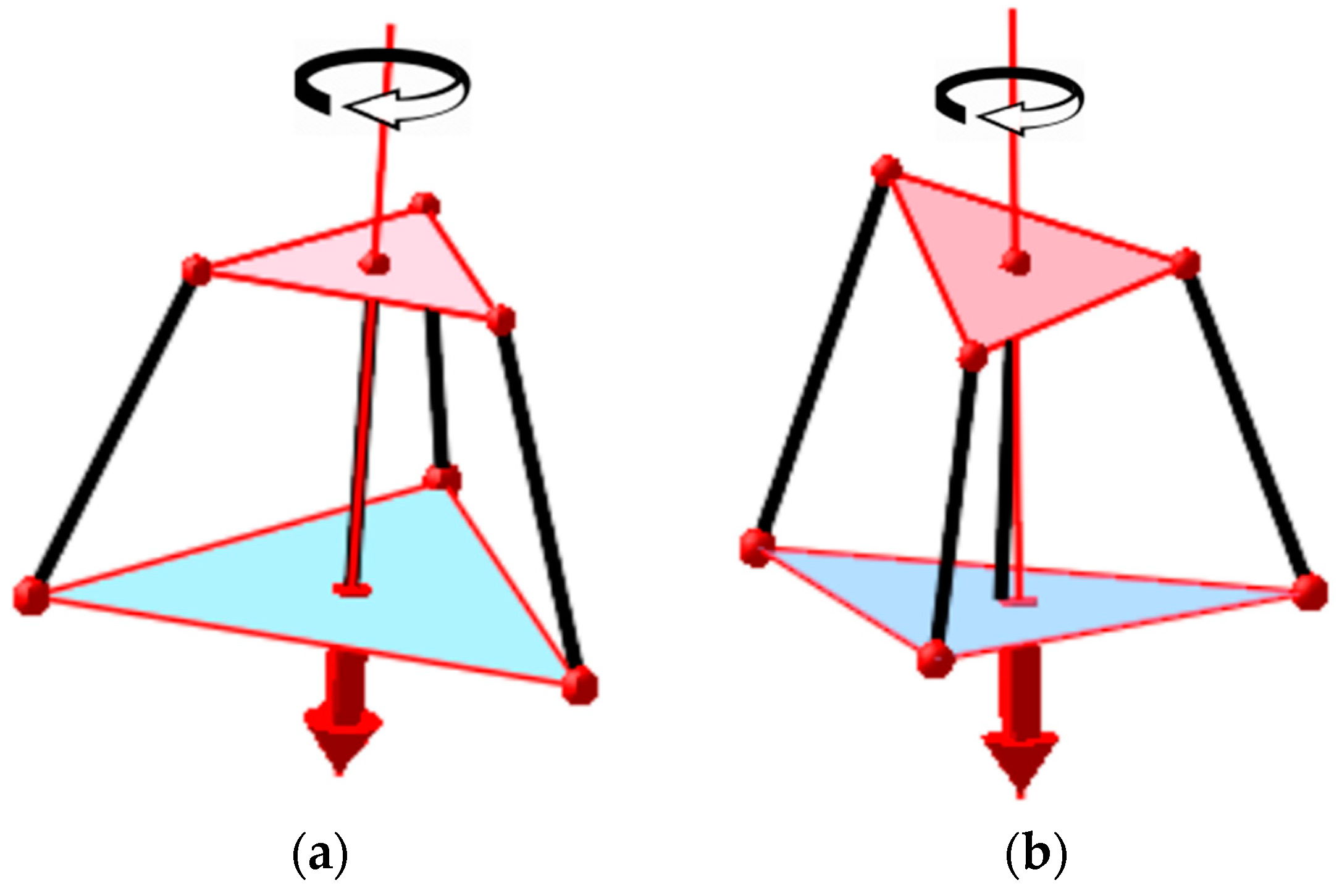
  • The 3UPS/S manipulator has good stiffness because it has a central leg connecting the base and top platforms.
  • This exoskeleton has a stand which is attached to a table. This stand reduces the weight of the exoskeleton acting on the patient.
  • The exoskeleton could be utilized to accommodate patients with the same average body size.
  • This exoskeleton can be used on both the hands.
  • This exoskeleton technology operates without the use of real-time computers or software.
  • It is an inexpensive rehabilitation system that may be used at home.
  • If one of the upper limbs is functional, the patients can set up the device on their own.
  • The only attachment point is at the hand. Some devices use multiple attachment locations.
This exoskeleton robot has few disadvantages when compared to other existing systems.
  • The robot does not perform a complete range of motion during wrist flexion and extension motions.
  • The top platform does not stay parallel to the base platform at the home position when the exoskeleton is idle. In this case, the central leg is an imaginary one and it is substituted by the human arm and wrist in the rehabilitation process.
  • This robot has singular configurations within its workspace.
  • This robot has more degrees of freedom than required to perform wrist motions.
  • This robot cannot be used for all age groups. It needs to be customized for different groups.
Among the disadvantages proposed for the exoskeleton robot, three of them are a little concerning but are not very dangerous for the patients. These are related to the singular configuration of the robot, redundant DOFs of the robot, and the top platform collision at home position. Section 4.4 provides a detailed analysis on singularity of the exoskeleton robot. If the moving platform is rotated around the Z-axis in both directions, the mechanism will cross the singularity. Hence, rotating the moving platform about the Z-axis can be avoided. Also, when all three UPS legs have equal lengths, the mechanism is in a singular configuration. For this reason, the selection of the starting position (or home position) having slightly different leg lengths is preferable.
Regarding the redundant DOFs of the exoskeleton robot, the top platform is only rotated about the X- and Y-axis, so that the additional DOF is not considered when employed for wrist joint rehabilitation. These two DOFs are enough to produce the two basic wrist movements such as flexion/extension and ulnar deviation/radial deviation.
Lastly, when the robot is attached to the human forearm, the collapsing of the top platform under its own weight will not happen. Thus, the top platform will remain parallel to the base platform at home position. In this case, the human forearm acts as the central leg of the robot (1S additional link).
It was identified that the proposed exoskeleton robot does not perform a full range of motion during flexion and extension motions. Thus, increasing the actuators’ stroke length, changing the radii of the moving and base platforms, and increasing the range of motion of spherical joints can improve the range of motion of the robot while performing flexion/extension motions.
Another limitation of the proposed exoskeleton robot is the fact that it cannot be used for all age groups. The exoskeleton robot needs to be customized, i.e., some parts need to be designed and manufactured according to the particular dimensions of the patient.
The main benefit of using a PM as a PW over serial mechanisms is its inherent capacity to more precisely position the end-effector (in this study, it is the human hand), which improves the trajectory. A PM is also known for being stiffer, which handles heavier loads or requires fewer structural support elements to prevent deformation from self-weight. Lastly, simpler and less expensive linear actuators can take the role of rotary actuators and costly speed reducers [7]. Also, it is demonstrated how a PM with three extensible legs, each with six DOFs, can be utilized as a PW to provide rotational motion. At each leg, there is an active prismatic pair that is situated between a spherical joint and a universal joint. One end of a central leg that connects the base and moving platform features a virtual spherical joint, making it a particular case of this mechanism. For the purpose of employing this robot for rehabilitation, the central leg and spherical joint are substituted with the human forearm and wrist joint.
A spherical joint is also known as ball-and-socket joint. It is modelled as two different parts, a socket (bottom part) and a ball (upper part). The bottom part is connected directly to the linear actuator using a nut and bolt and the upper part is connected directly to the top platform using a nut and bolt. The ball is modelled inside the socket with a clearance between them. The spherical joint has three DOFs. This allows the top platform to rotate about three axes. It can be seen in Figure 1.
A universal joint has two shaft yokes. The first yoke is connected directly to the bottom platform using a nut and bolt. The second yoke is connected via a coupling specifically designed to connect the universal joint yoke to the linear actuator. The universal joint has two DOFs and it allows for the holding and positioning of the linear actuator.
The 3UPS/S robot has a central virtual leg. One end of the leg is firmly attached to the bottom platform and the other end is connected to the top platform via a spherical joint. It is called a virtual leg because in reality it actually represents the forearm and the spherical joint represents the wrist joint. The robot functions as a 3UPS/S manipulator only when it is connected to the forearm and wrist joint, or it can be said that the 3UPS/S architecture is complete when it is attached to the user where the forearm with a wrist joint is the real central leg.

3. Exoskeleton Manipulator Structure for Wrist Rehabilitation

The design of the exoskeleton is primarily focused on real-world rehabilitation. Consequently, the exoskeleton device must be able to perform normal human arm movements. Since the device is meant to be worn, additional safety measures must be implemented to ensure the wearer’s wellbeing. Furthermore, being mobile is usually not a need for such a system. The device is therefore grounded to support large loads. Furthermore, because human movements include low accelerations and velocities, the device’s inertia has no effect on how it operates. As a result, the exoskeleton’s design has mostly focused on the robot’s kinematic design [36].

3.1. Manipulator Design

The exoskeleton is based on the architecture of a 3UPS/S PW manipulator. Three UPS actuated legs control the moving platform. Figure 2 shows the exoskeleton’s basic kinematic structure. To carry out the required orientation, the prismatic pairs are active ones. Additionally, it features a central leg that connects the base and moving platforms with a spherical joint (WS) at one of its ends. The robot was made more rigid by its fixed central leg to ensure only rotational motion.
When comparing Figure 1a and Figure 2, leg 1 denotes a leg with joints U1P1S1, leg 2 denotes a leg with joints U2P2S2, and leg 3 denotes a leg with joints U3P3S3. The central leg denotes the forearm of the user when the robot in Figure 1a is attached to the user’s forearm during rehabilitation therapy. Similarly, WS joint denotes the wrist joint of the user. In Figure 2, top platform and base platform of the robot denote the moving platform and base platform in Figure 1b.
The palm splint, which is attached to the operator during operation, is housed in the moving platform. Spherical joints are spaced 120° apart around the top platform. The top moving platform and the three extensible links are connected via these spherical joints. Similarly spaced 120° around the base platforms are the universal joints and these are connected at the opposite end of the extensible links. To move the top platform, the leg length is varied using linear actuators positioned along the leg. Note that in reality, the spherical joint symbolizes the human wrist joint and the fixed central leg connecting the base and moving platforms represents the forearm of a human. When operating, the robot is worn so that the operator’s wrist joint is lined up with the centre of the spherical joints. Natural arm movements are preserved because of this arrangement, which matches the kinematic structure of the robot with that of the human arm. An ergonomic palm splint and Velcro straps aid to maintain this position. Mapping the robot’s configuration to the arm position is made even more efficient by using the 3UPS/S kinematic structure of the robot.
The operator’s forearm dimensions were used to figure out the exoskeleton dimensions. At first, the leg lengths were determined. This involves adding the lengths of the spherical joint, universal joint, and fully extended actuator in addition to the base and moving platforms thickness. As a result, the distance between the moving and base platforms was obtained. This allows for the designation of the location where the top and base platforms should be placed on the forearm. Next, measurements were taken of the forearm size, which is where the base and movable platforms are supposed to be mounted. Keep in mind that because the exoskeleton is an SPM, the platform’s height is kept constant as it operates. The moving and base platforms diameters are constrained by the dimensions of the human arm. The base platform is actually attached to the forearm.

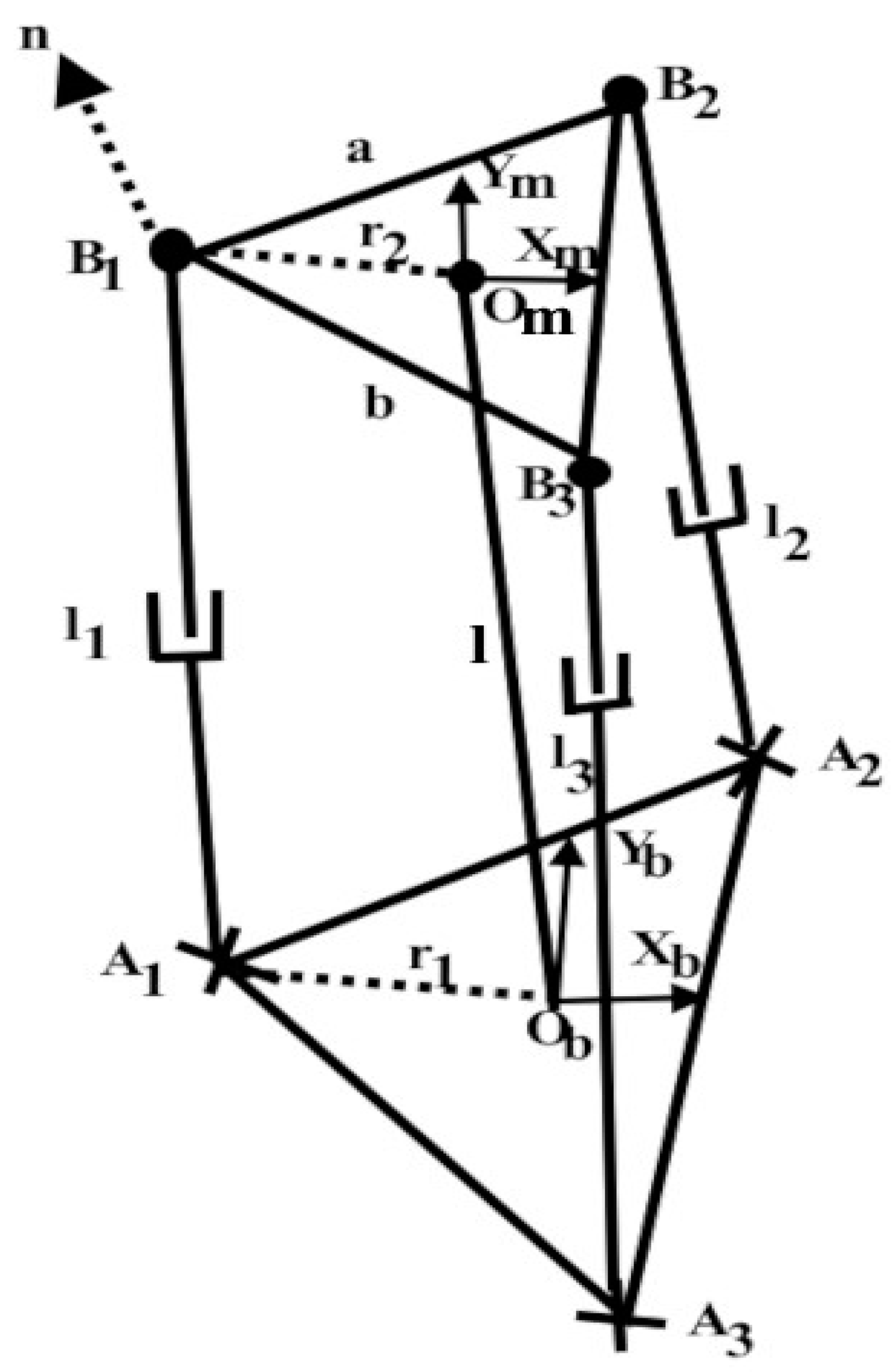
3.2. Inverse Kinematics

The 3UPS/S parallel manipulator is composed of three expandable links, l1, l2, and l3, as shown in Figure 3. The coordinate axes are affixed to the platforms of the exoskeleton for analytical purposes. Joints B1, B2, and B3 are kept 120° apart, as well as A1, A2, and A3, therefore, these joints appear at the vertices of an equilateral triangle. The frames {b} and {m} are fixed to the base and moving platforms.
To calculate the rotational motion of the 3UPS/S robot, the Euler angle representations were used. The designed parallel robot has three rotational DOFs. This robot is expected to rotate about the centre of the top platform. Thus, the centre of the top platform is at a fixed distance from the base platform or the length of the central leg of the robot is fixed. Thus, the 4 × 4 homogeneous transformation matrix in Equation (1), which includes the orientation and position, can be used to show this transformation [3].
[ T ] b m = c ϕ c θ c ϕ s θ s Ψ s ϕ c Ψ c ϕ s θ c Ψ + s ϕ s Ψ 0 s ϕ c θ s ϕ s θ s Ψ + c ϕ c Ψ s ϕ s θ c Ψ c ϕ s Ψ 0 s θ c θ s Ψ c θ c Ψ l 0 0 0 1
During flexion and extension motions, the top platform of the robot is rotated only by the Ψ angle about the X-axis. Then, during ulnar and radial deviation motions, the top platform of the robot is rotated only by the θ angle about the Y-axis. Since this robot is used only to perform said motions, there is no need of rotation about the Z-axis; hence, the angle ϕ about the Z-axis is always zero. The fixed length of the central leg of the robot is denoted by “l” (l = 171.43 mm). The radius of base and top platforms is r1 = 82 mm and r2 = 45.5 mm, respectively.
The coordinate frame {b} (Figure 3) is fixed to the base platform’s centre, with the Xb and Yb axes located on its plane. The frame {m} is attached to the moving platform, where the Xm and Ym axes rest on the moving platform plane. Z-axes of both frames are normal to the platform planes. The mechanism has three DOFs. As a result, the moving platform has three rotational DOFs. The symbol “li” indicates leg length. Equation (2) provides the coordinates of the universal joints with respect to the frame {b}.
O b A 1 = r 1 , 0 , 0 T
O b A 2 = r 1 cos 60 , r 1 sin 60 , 0 T
O b A 3 = r 1 cos 60 , r 1 sin 60 , 0 T
The coordinates of the centres of spherical joints with respect to frame {m} are given in Equation (3):
O m B 1 = r 2 , 0 , 0 T
O m B 2 = r 2 cos 60 , r 2 sin 60 , 0 T
O m B 3 = r 2 cos 60 , r 2 sin 60 , 0 T
The spherical joint’s position vector with respect to base frame {b} was obtained using Equation (4):
O b B i 1 = [ T ] b m O m B i 1
The leg lengths or the actuation needed to rotate the moving platform was found out using Equation (5):
l i = O b A i O b B i i = 1 , 2 , 3
For a serial link robot, solving the forward kinematics is easy and the analytical form exists. However, for a parallel link robot, solving the forward kinematics is very complex and the analytical form may not exist. For a serial link robot, the inverse kinematics is typically complex and the analytical form may not exist; however, for a parallel robot, the inverse kinematics is easy to determine and the analytical form exists. Thus, using Equations (1)–(5), the inverse kinematics of the proposed parallel exoskeleton robot can be obtained easily.

3.3. Workspace

The capability of a robot can be evaluated in terms of its workspace. The robot workspace depends on the dimensions of the robot and various other factors. It is usually defined in a cartesian coordinate system. The workspace of the joint motions is called the joint workspace. It is possible to calculate the joint workspace from the inverse kinematic model [37]. The rotational workspace and joint workspace of the proposed robot are presented in Section 4.3.
The specific factors that affect the workspace of any parallel robots are the actuated joint variables, the range of joint’s motion, the mechanical interferences between the links, degree of freedom, configuration constraint of various joints, mechanical collision of different components, actuator’s stroke, sliding pair limitation, rotation angle limitation of the Hooke joint, and singular configurations [38,39,40].
Selecting the right structure size of a parallel robot for the task at hand can be challenging because there are numerous performance criteria that need to be taken into consideration. Furthermore, because these criteria depend on the position of the moving platform and must be assessed across the robot’s whole workspace, they are challenging to analyse. It is obvious that the orientation workspace is crucial to the design process. All points on a moving platform that can be reached for any orientation within a set defined by the orientation angles are collectively referred to as the total orientation workspace. It explains an essential feature of a parallel robot by providing the useful workspace [41].

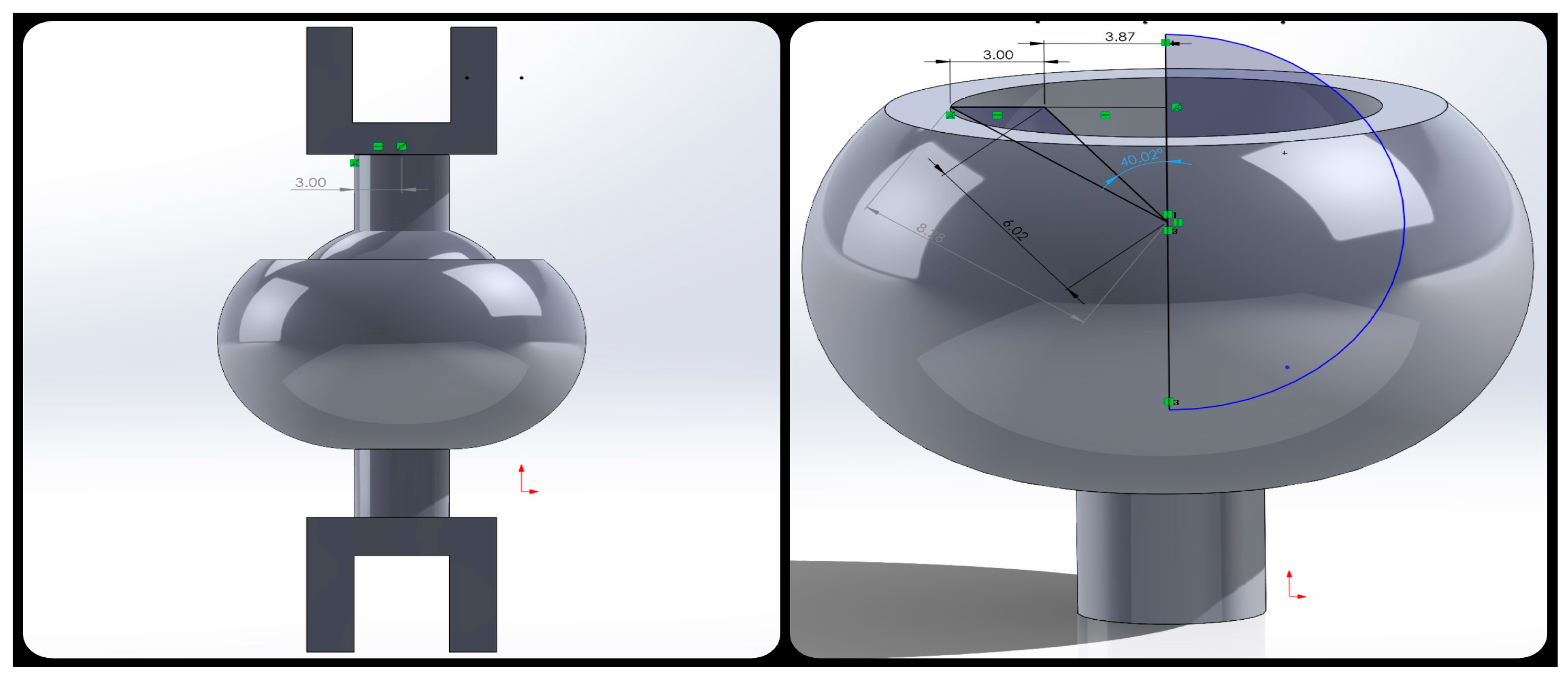
3.4. Custom-Made Spherical Joint

The custom-made spherical joint has three DOFs. It was found that the commercially available spherical joints could not properly satisfy the workspace requirements. Consequently, the conventional spherical joint was replaced with a three-DOF spherical joint that was particularly 3D printed using additive manufacturing technology.
As can be seen in Figure 4, the ROM of the joint was determined from the 3D model and found to be 40.02° in one direction. The spherical joint ROM is crucial for the computation of the robot’s workspace. The spherical joint’s ball and socket were modelled as a single component with some clearance between them (0.73 mm). Using the SolidWorks 2022 software, the moving platform, base platform, spherical joints, palm splint, and coupling that joins the universal joint and actuator were designed. Then, using additive manufacturing technology, these parts were manufactured and then assembled.

4. Kinematics, Workspace, Singularity, and Simulation

4.1. Exoskeleton Range of Motion and Human Wrist Joint Motions

The patient’s upper limb is subject to kinematic constraints when using a wrist exoskeleton. If the wrist exoskeleton does not obstruct the operator’s normal wrist motions or workspace, that is advantageous. Additionally, exoskeleton technology needs to be able to equal or surpass human capabilities. The human hand includes five fingers and a wrist joint. Two DOFs exist in the human wrist. Flexion, extension, radial deviation, and ulnar deviation are the four basic wrist movements. The normal range of motion (ROM) of the wrist is given in Table 2.
Table 2 displays the maximum ROM limits for a human wrist joint as determined by the American Academy of Orthopaedic Surgeons (AAOS) for various wrist motions, as well as the achieved ROM and overall capability of the exoskeleton robot.
The exoskeleton depicted in Figure 5 performs various wrist movements (Supplementary Video S1). The exoskeleton has a stand which rests on the table. The one end of the forearm (near to the elbow joint) rests inside the base platform. From the centre of the base platform, there is a circular extension to support or rest the forearm. This support can be further extended to the centre of the manipulator to hold the forearm from dropping down for paralyzed limbs. Also, a larger-sized stand can carry the maximum weight. Using a Velcro strap, the hand is attached to the palm splint. There are many openings in the palm splint to place the Velcro strap to adjust to different hand sizes. A user with the robot can be seen in Figure 5f.
Table 2 displays the capabilities of the exoskeleton, the exoskeleton’s achieved ROM, and its desired range. It is evident that for some wrist joint motions, the exoskeleton design satisfies the required workspace requirements. The device can only move the wrists 31° in the flexion and extension directions, that is, 49° and 39° less than what a human wrist joint can perform. As can be observed, the exoskeleton achieves 100% ROM while performing wrist ulnar deviation and radial deviation motions.

4.2. Inverse Kinematics Solution

The moving platform orientation was used to calculate the final homogeneous transformation matrix. The maximum stroke length for each linear actuator on the robot is 50 mm.
Figure 6 illustrates the change in the leg length during flexion and extension motions. During the extension motion, the moving platform is rotated about the Xm-axis in a clockwise direction (+ve direction), and it is rotated in an anticlockwise direction for flexion motion. The three actuators are initially positioned (the home position) at the halfway point of the stroke (25 mm). The actuator has a 25 mm maximum extension and retraction from the home position. Leg l2 extends, leg l3 retracts, and leg l1 remains in the same mid position during the extension motion. Leg l2 retracts, leg l3 extends, and leg l1 is not activated during the flexion motion. As a result, the moving platform can be oriented in the desired direction. Note that the movable platform only permits rotational motion.
Figure 7 depicts how leg lengths vary during wrist ulnar deviation and radial deviation motions. During ulnar deviation motion, the moving platform is rotated about the Ym-axis in an anticlockwise direction (−ve direction), and it is rotated clockwise for radial deviation motion. When the robot performs the ulnar deviation motion, leg l1 retracts while leg l2 and leg l3 simultaneously extend. Leg l1 extends and legs l2 and l3 retract in the same manner during radial deviation motion. The inverse kinematics solutions shown in Figure 6 and Figure 7 were used to control the leg lengths of the robot.
It is understood from Figure 6 and Figure 7 that, when the top platform of the 3UPS/S exoskeleton robot was rotated smoothly, all the legs of the exoskeleton robot moved smoothly in tandem.

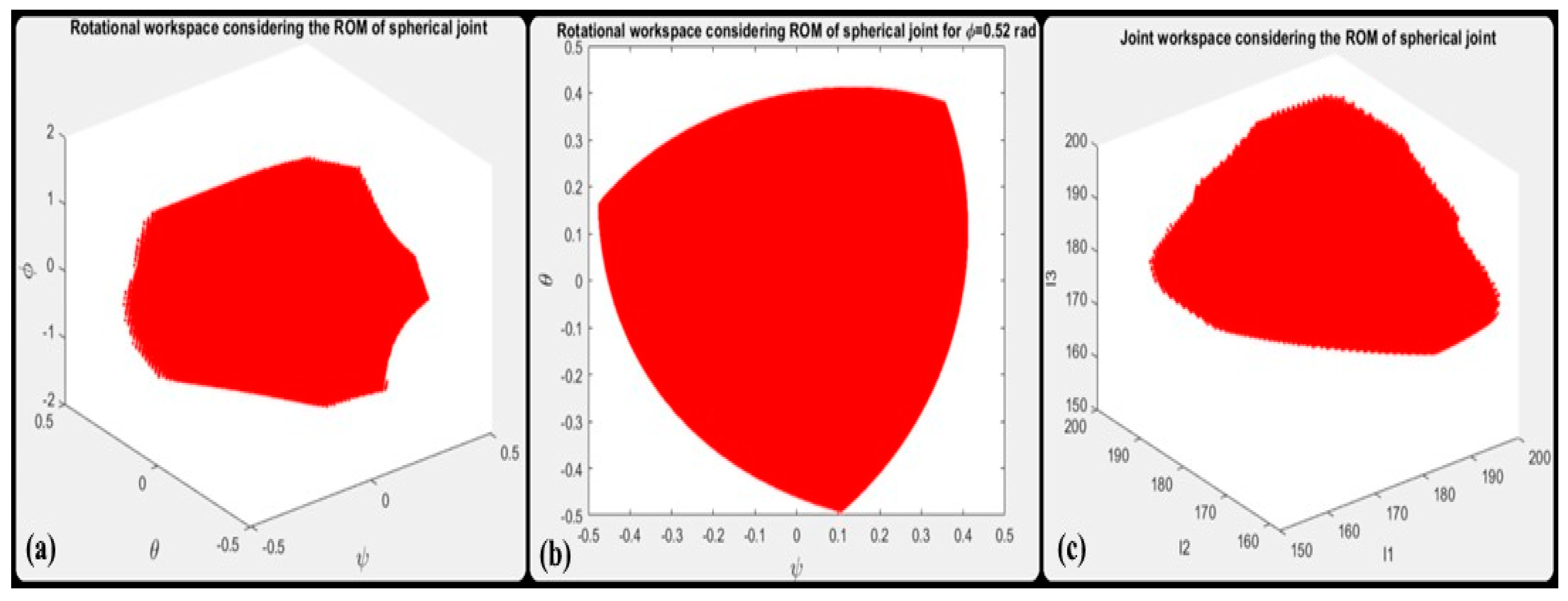
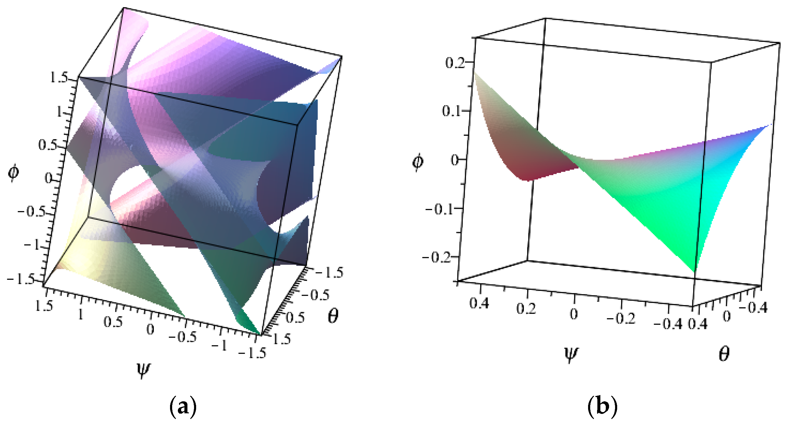
4.3. Rotational and Joint Workspaces

Using Equation (1), the rotational workspace and joint workspace when the moving platform is rotated from −π/2 to +π/2 about three axes parallel to Xb, Yb, and Zb, which intersect at point Om, are found. The distance between the base and moving platform along the Z-axis was considered fixed, where l = 171.43 mm (this length is measured from base platform to the centre of the spherical joint). Then, the rotational workspace and joint workspace for the full stroke length of the actuator are plotted. As it is known, the total stroke of the actuator is 50 mm, and the leg length of the robot varies in the range of 146.43 mm ≤ li ≤ 196.43 mm. Figure 8 shows the rotational and joint workspace of the 3UPU/S robot plotted within the limits of the leg length using MATLAB R2022a (MathWorks, Natick, MA, USA). The rotational workspace in two dimensions by setting ϕ = 0.52 radian is shown in Figure 8b.
Next, considering the ROM of the spherical joint, the rotational and joint workspaces of the robot are found. This is conducted by finding the angle between the vectors l i and n . Here, l i represents the vector associated with the legs of the robot and n represents the normal vector of the moving platform. The vector l i has already been found while solving the inverse kinematics using Equation (5). The vector n is normal to the plane formed by the centres of the three spherical joints at the moving platform. To find the plane, the position vector of all the three spherical joints connecting the moving platform with respect to the frame {b} is found. This has also been found out while solving the inverse kinematics problem using Equation (4). The vectors a and b (Figure 3) are obtained using Equation (6).
a = B 2 B 1
b = B 3 B 1
n = b × a
The angle (α) between the vectors   l i and n is obtained using Equation (7).
sin α = | l i × n | l i n
cos α = l i · n l i n
tan α = sin α / cos α
The angle (α) varies in the range of −0.698 rad ≤ α ≤ 0.698 rad which represents the ROM of the spherical joint. The rotational and joint workspaces within the limits of leg length and within the limits of the ROM of spherical joints were plotted using MATLAB and are shown in Figure 9. This represents the actual rotational workspace and joint workspace of the robot. The rotational workspace and joint workspace in two dimensions are shown in Figure 9b by setting ϕ = 0.52 radian.
The rotational workspaces together for both cases are shown in Figure 10. The blue colour workspace in Figure 10 is for the case of considering only the limits of the legs and the red colour workspace considers both the leg limits and limits of the ROM of the spherical joints. The reduced workspace results from the influence of the limitation of the ROM of the spherical joints.
The slices of the rotational workspace when the moving platform is rotated in clockwise and anticlockwise directions about the Zm-axis for various angles of rotation (ϕ) are shown in Figure 11.
In Figure 11, the red colour slice is obtained for the angle ϕ = 0 rad. The blue slices are obtained when ϕ = ±0.523 rad, the cyan colour slices are obtained for the angle ϕ = ±1.047 rad, and the yellow colour slice is obtained for ϕ = 1.57 rad.
The results of rotational workspaces shown in Figure 8, Figure 9, Figure 10 and Figure 11 conclude the limitations in the orientation of 3SPS/S spherical wrist robots. It was observed that the workspace reduced because of the limited ROM of the spherical joints. It was also observed that the workspace of the robot reduced when the moving platform rotated about the Z-axis. At 90° rotations about the Zm-axis, the workspace is very limited. The workspace is symmetrical when the moving platform rotates about the Zm-axis in both directions.
The total ROM of the custom-made spherical joint is found to be 40.02°. The rotational workspace and joint workspace of the robot were plotted using MATLAB. The rotational and joint workspaces were obtained considering initially only the limits of the leg lengths and then later including the ROM of the spherical joints. It is found that the spherical joint’s limited ROM causes a reduction in the workspace. Additionally, it is noted that, as the yaw angle (ϕ) increases, the robot’s workspace decreases. The workspace is quite limited at ϕ = 1.57 rad. When the moving platform is rotated about the Z-axis in both directions, the workspace is symmetrical. Therefore, in order to achieve the full ROM of wrist flexion and extension motions, the spherical joints need to be redesigned.
By observation, the spherical joints have no influence on the results presented in Table 2. Even though the spherical joint highly contributes to a reduced workspace, the other reasons will be the limitation in the stroke of the actuator, radii of the base and moving platforms, and the distance of the moving platform with respect to the base platform. If more ROM is required for wrist flexion and extension motions, then the spherical joints need to be replaced.

4.4. Singularity Analysis Using Geometric Algebra

In this section, the singularity analysis of the 3UPS/S spherical wrist (Figure 2) is presented. The singularity analysis is performed using the apparatus of geometric algebra and it is based on the approach introduced in [42,43]. Firstly, a brief introduction to geometric algebra is presented.
Geometric algebra could be considered a further development of Clifford algebra. Clifford algebra was created in the 19th century, and in the second half of the 20th century, this algebra has been further developed into a unified language named geometric algebra. A single basic kind of multiplication called the geometric product between two vectors is defined in geometric algebra. The geometric product (ab) is composed of the inner product ( a · b ) and outer product ( a b ) of two vectors, i.e.,
a b = a · b + a b  
The inner product a · b is scalar-valued (grade 0). The geometric algebra G n is a 2 n -dimensional algebra, i.e., it generates exactly 2 n linearly independent elements. The elements of geometric algebra are as follows: scalar (grade 0); vector (grade 1); bivector (grade 2) is the result of the other product of two vectors; and k blade ( a 1 a 2 a k ) is the result of the outer product of k vectors. The integer k is named grade. The geometric algebra contains nonzero blades of maximum grade which are called pseudoscalars. For example, the unit pseudoscalar of G 3 of a 3D Euclidean metric space with the standard orthonormal basis { e 1 , e 2 , e 3 } could be written as
I 3 = e 1 e 2 e 3 = e 1 e 2 e 3 ,
and the inverse of this pseudoscalar is
I 3 1 = e 3 e 2 e 1
In this paper, the basis vectors obey the following rules:
e i · e j = δ i j ;   δ i j = 1   ( i = j ) ;   δ i j = 0   ( i j ) ;   e i e i = 0
A generic element of geometric algebra is called a multivector, which can be written as
M = k = 0 n M k ,
where M k denotes the k-vector part of the multivector M.
For the purpose of the singularity analysis, the screws are represented in terms of geometric algebra.
In geometric algebra G 3 , a general screw can be written as a multivector [42], i.e.,
s = u + r u + h I 3 u = v 1 e 1 + v 2 e 2 + v 3 e 3 + b 1 e 2 e 3 + b 2 e 3 e 1 + b 3 e 1 e 2 ,
where ‘u’ is the direction of the screw axis; ‘r’ is the position vector of a point of the screw axis; ‘h’ is the pitch of the screw; v i and b i are scalar coefficients; and I 3 is the unit pseudoscalar I 3 = e 1 e 2 e 3 of the geometric algebra G 3 .
The same screw can be written as a six-dimensional vector in G 6 [42]:
S = v 1 e 1 + v 2 e 2 + v 3 e 3 + b 1 e 4 + b 2 e 5 + b 3 e 6
The 3UPS/S parallel mechanism has four legs, and each of the UPS legs has full mobility while the fourth leg (1S) does not possess full mobility. To characterize this leg as a full mobility one, it was supposed that the remaining degrees of freedom are represented by dummy joints, which are considered driven but locked joints. In other words, three dummy-driven joints were introduced. The notations of screws in this paper are as follows: small letter ‘s’ indicates a screw written in the geometric algebra G 3 , while a screw given in G 6 is denoted with capital letter ‘S’.
The screws associated with the joints of each UPS leg can be noted as S   j 1 (revolute joint), S   j 2 (revolute joint), S   j 3 (prismatic joint—driven), S   j 4 r e v o l u t e   j o i n t ,   S   j 5 r e v o l u t e   j o i n t ,   S   j 6 r e v o l u t e   j o i n t ,   a n d   j = 1,2 , 3 —leg number (Figure 12). The screws associated with the fourth leg (1S) are S   4 1 (revolute joint), S   4 2 (revolute joint), and S   4 3 (revolute joint). Here, each spherical joint is represented by three revolute joints. The screw axis of the revolute joint is along the joint axis and the derestriction of the screw associated with the prismatic joint is along the direction of translation. These screws are calculated using Equations (8) and (9) while the components ‘u’ and ‘r’ can be obtained from the equations given in Section 3.2. The screws associated with the revolute joints are lines, i.e., screws with zero pitch, while the screws associated with the prismatic joints have infinite pitch ( S p r i s m a t i c = b 1 e 4 + b 2 e 5 + b 3 e 6 ).
Now, one can form the outer product of five screws for each leg:
A   j = S   j 1 S   j 2 S   j 4 S   j 5 S   j 6 ,   j = 1,2 , 3 .
Here, A   j is a five-blade and it is clear that S   j 3 is not included in Equation (10), i.e., the screws associated with the active joint (the prismatic joint in this case) are not included in the blade. Then, the duality operation can be applied to obtain the dual of the five-blade, i.e.,
D   j = A   j I 6 1 ,   j = 1,2 , 3
where I 6 1 is the inverse of the unit pseudoscalar I 6 = e 1 e 2 e 3 e 4 e 5 e 6 of the geometric algebra G 6 .
The dual of a blade represents the orthogonal complement of the subspace represented by the blade in a non-degenerate space. This implies that the inner product of each vector of the blade A   j with the dual D   j is equal to zero, i.e.,
S   j i · D   j = 0 , i = 1,2 , 4,5 , 6
Since A   j is a five-blade, the dual D   j is a vector (one-blade) in this case. In the case of the UPS leg and keeping in mind Equation (12), the reciprocal screw theory can be used in order to simplify the finding of the dual of the five-blade A   j . It is known that a line intersecting all five screws (having zero pitch) is reciprocal to them. Let R = m 1 e 1 + m 2 e 2 + m 3 e 3 + n 1 e 4 + n 2 e 5 + n 3 e 6   j be the reciprocal screw to the five screws S   j i , i = 1,2 , 4,5 , 6 . Then, it can be deduced from the reciprocity properties and Equation (12) that the dual can be written as
D   j = n 1 e 1 + n 2 e 2 + n 3 e 3 + m 1 e 4 + m 2 e 5 + m 3 e 6
The reciprocal screws for each UPS leg in the geometric algebra G 3 are obtained using Equation (8), i.e.,
r   j   = u A j B j + O b A j u A j B j , j = 1 , 2 , 3
Expanding Equation (14) for the first leg, one can obtain the reciprocal screw and dual vector in the geometric algebra G 6 :
R       1 = 1 N ( m 1   1   e 1 + m   1 2   e 2 + m   1 3   e 3 + n   1 1   e 4 + n   1 2   e 2 + n   1 3   e 3 ) ,
D       1 = 1 N ( n 1   1 e 1 + n   1 2   e 2 + n   1 3   e 3 + m   1 1   e 4 + m   1 2   e 2 + m   1 3   e 3 ) ,
where m   1 1 = r 1 r 2 cos ϕ c o s θ ; m   1 2 = r 2 s i n ϕ c o s θ ; m   1 3 = r 2 s i n θ + l ; n   1 1 = 0 ; n   1 2 = r 1 ( r 2 s i n θ + l ) ; and n   1 3   = r 1 r 2 s i n ϕ c o s θ .
N = 2 l r 2 s i n θ r 1 r 2 cos ϕ + θ r 1 r 2 cos ϕ θ + r 1 2 + r 2 2 + l 2
Similarly, the reciprocal and dual vectors for the other two legs can be obtained. Their components are lengthier and that is why they are not listed here.
Each UPS leg has full mobility with one driven joint and the duals associated with any such leg are vectors. The fourth leg (1S) has limited mobility and does not have active joints. Assuming that there are three dummy active joints, which are represented by the screws S   4 d 1 , S   4 d 2 , and S   4 d 3 , then the duals associated with these dummy joints can be written as
D d 1   4 = ( S   4 1 S   4 2 S   4 3 S   4 d 2 S   4 d 3 ) I 6 1 ,
D d 2   4 = ( S   4 1 S   4 2 S   4 3 S   4 d 1 S   4 d 3 ) I 6 1 ,
D d 3   4 = ( S   4 1 S   4 2 S   4 3 S   4 d 1 S   4 d 2 ) I 6 1 ,
The duals from Equations (17)–(19) are vectors (one-blade). Then, the dual blade for the 1S leg is
D   4 = D d 1   4 D d 2 D d 3   4   4
All duals needed for the singularity condition are obtained and this condition is written as
D   1 D   2 D   3 D d 1   4 D d 2 D d 3   4   4 = 0
The manipulator is in a singular configuration when these vectors are linearly dependent.
It is shown in [42,43] that the dummy vector could be eliminated. Then, after the elimination, the dual associated with a leg with limited mobility involves only the passive joints, i.e., Equation (20) becomes
D   4 = λ ( S   4 1 S   4 2 S   4 3 ) I 6 1 ,
where D   4 is a three-blade in this case; and λ is a scalar.
Then, the condition for singularity can be written as
D   1 D   2 D   3 D   4 = 0
This condition of singularity forms a six-blade. The three-blade D   4 can be factorized into three vectors which will mean that they are the three duals associated with the three dummy joints of the fourth leg. This implies that the singular condition is constituted by the outer product of six vectors. Therefore, the manipulator is in a singular configuration when these vectors are linearly dependent.
The algebraic expression of the singular condition can be obtained by Equation (23), i.e.,
B = ( D   1 D   2 D   3 D   4 ) I 6 = 0
The expression B is a scalar-valued function of design and input parameters. It is parametrized by the rotation angles Ψ, θ, and ϕ in this case. The singular surface obtained from Equation (24) is illustrated in Figure 13a. The figure shows the singular surface for the three rotation angles within the range [ π 2 , π 2 ]. In our analysis, the singular surface within the workspace of the mechanism is of greater interest and Figure 13b shows the singular surface with the dimensions of the workspace (see Figure 11).
Further, some slices of the singular surface can be produced for the sake of simplicity and illustration. In this case, singular curves are obtained.
Two slices of the singular surface are shown in Figure 14 together with a particular singular point. The singular curve is illustrated in red colour in Figure 14.
Two singular configurations of the mechanism are also shown in Figure 14, which are illustrated as points (blue points). The singular configurations of the mechanism corresponding to these points are shown in Figure 15.
Since the six dual vectors from Equation (21) or Equation (23) are linearly dependent in a singular configuration, the uncontrollable instantaneous twist can be obtained from the outer product of any five vectors, i.e., the dual of the five-blade, e.g.,
U = ( D   2 D   3 D d 1   4 D d 2 D d 3 )   4   4 I 6 1 = ( D   2 D   3 D   4 ) I 6 1
Here, the uncontrollable instantaneous motion is a vector (one-blade) and it is shown as red arrow in the figures.
In the singular configuration shown in Figure 15a, all three legs have equal lengths and all three rotation angles are zero. In this case, four of the dual vectors (out of six) are linearly dependent. This situation can be illustrated by the reciprocal screws, i.e., the four lines along the legs meet in a single point, which means that they are linearly dependent. Here, the uncontrollable motion in this singular configuration is a rotation (a screw with zero pitch) around the line along the 1S leg and the instantaneous rotation axis is illustrated as red arrow in the figure. In the second singular configuration (Figure 15b), the six dual vectors are linearly dependent. In this case, the uncontrollable motion is also rotation and the instantaneous rotation axis slightly differs from the 1S leg line. The screw axis of the uncontrollable motion intersects all reciprocal screws, i.e., the three lines along the UPS legs. Also, it passes through the centre of the central spherical joint of the 1S leg. The geometrical explanation of this fact is that the reciprocal screws of the three revolute joints, which substitute the central spherical joint, could be arbitrary lines crossing the three joint axes. These three arbitrary lines represent the dummy joints. Thus, the axis of the uncontrollable rotation passes through the centre of the central spherical joint and, therefore, intersects the three axes of the dummy joints. To illustrate this, an example for a singular configuration of the UPS/1S mechanism is shown in Figure 16.
Although the singular configuration ( ψ = 0.5 , θ = 0.9525498668 , ϕ = 0.2 ) in Figure 16 is outside the workspace boundaries, it better illustrates the crossing of the lines. The crossing of any two lines is demonstrated with a black circle in the figure.
It is clear from the analysis that singularities exist within the obtained workspace of the mechanism. Therefore, the manipulator can incur singularities during movement. For example, if the moving platform rotates around the Z-axis in both directions, the mechanism will cross the singularity. Also, when all three UPS legs have equal lengths, the mechanism is in a singular configuration. For this reason, the selection of the starting position (or home position) having slightly different leg lengths is preferable. As a rule, try to avoid the singularity during the movement of the mechanism when this is possible.

4.5. Actuators, Control, and Safety

Electrical actuators were selected for the exoskeleton application. Compared to pneumatic actuators, electrical actuators have a substantially larger bandwidth but an inferior power-to-weight ratio. A single actuator that provides a large bandwidth and a high power-to-weight ratio does not exist. An actuator’s dynamic response is determined by its bandwidth. A limited-bandwidth actuator reduces system transparency by not being able to deliver the operator high-frequency forces [36]. The Actuonix Motion Devices (Actuonix Motion Devices Inc., Saanichton, BC, Canada) L12-50-210-6-I actuator is the one which was chosen for actuation. Because it is equipped with an internal position controller, the actuator will move to the desired location. It has a 210:1 gear ratio with a total stroke length of 50 mm. Its top speed at no load is 6.5 mm/s, and it can handle up to 80 N of force. It weighs 40 g. The device has a stall current of 460 mA and a maximum input voltage of 7.5 V.
All three actuators are controlled simultaneously by an Arduino board. The motors are powered by an external battery. The controller is then given inverse kinematic-based trajectory directives. The workspace of the exoskeleton is greater than that of the human arm for specific joint actions (see Table 2). To protect users from these circumstances, hardware stops and software controls are used. Additionally, emergency stop switches are offered. The total cost of setting up the system is less than EUR 390, including the universal joints, actuators, Arduino board, battery, and charger.
The control of the proposed exoskeleton is achieved by programming an Arduino board with the inverse kinematic solutions, which moves the human hand using linear electric actuators. In order to follow the desired path, an actuator command must be produced by a control system. The actuator’s speed can be adjusted with these commands. No sensors are required to provide feedback regarding the orientation and position of the actuator. For this application, simple position control is sufficient and advanced dynamic control is not required.
Finding a control for a dynamical system in the event of an initial disturbance and bringing it to equilibrium as quickly as possible are the goals of optimal control. Since there was no disturbance, optimum control was not applied in this project. Furthermore, our system lacks sensors for feedback, which is a disadvantage of optimal control because some feedback is necessary for optimal control. Additionally, our system is free from uncertainties such as real-time perturbations, therefore a robust control is neither required nor utilized [44].
Since the patients set up and operate the device themselves, the suggested exoskeleton robot uses an open-loop position control to reduce complexity in the design and control strategy. The desired path planning and linear joint movements are controlled by an Arduino control board. The exoskeleton is powered by three linear actuators. The driving link motion has been calculated and interpolated for all points found during the inverse kinematics. After that, an Arduino controller receives the acquired actuator movements and powers the exoskeleton. The motor is moved in each necessary position by the controller using an interpolated step motion. There is a delay before going to the next desired position in order to ensure user safety. The user can immediately stop the device using an emergency switch if it becomes uncomfortable. The electric motor’s range is restricted by the Arduino IDE 2.1.1 software, and it is evident that this falls inside the intended stroke length which is at a safe operating range for the given purpose.
Furthermore, the modest accelerations and velocities corresponding to human motions guarantee that the device’s inertia has a minimal effect on how it functions. The robot’s kinematic design was therefore taken into careful account when designing the exoskeleton. The robot kinematics and compactness of the design were prioritized during the design phase. In order to prevent transmission nonlinearities and backlash, a direct drive mechanism was employed. The exoskeleton weighs approximately 0.4 kg as a result. To lessen the user’s discomfort, the device was grounded as a result. Software limitations have been applied to guarantee safety for users. There is also an emergency stop switch available. Future plans include the use of software stops in addition to mechanical stops at workspace boundaries to guarantee operator safety. Each actuator will have torque restrictions in software, as well as mechanical hard stops and adjustable position soft stops. A force sensor will be implemented in the exoskeleton robot which can measure the interaction force with the user [36].

5. Discussion and Future Work

In 1993, Innocenti and Parenti-Castelli [45] studied a spherical wrist parallel manipulator which could perform pure orientation in three-dimensional space. They identified that the rotational freedom of each leg of the 3SPS/S parallel wrist having two spherical pairs at its extremities did not affect the location of the moving platform. However, they performed a case study using a 3UPS/S manipulator which was obtained by replacing one spherical pair with a universal joint which eliminated the aforementioned rotational freedom.
A 3UPS/S manipulator is used for the first time in an exoskeleton system as a wrist rehabilitation robot in this research, i.e., the 3UPS manipulator combined with the human wrist and arm constitute the 3UPS/S architecture of the robot. This is a new approach adopted in this work. The prismatic joints are the active ones of this robot. The top platform of the robot has to be rotated about a fixed centre. In order to achieve the desired motion, the prismatic joints are actuated all together at the same time but in different directions. This approach to rotate the top platform without shifting its centre needs some accurate inverse kinematics solutions.
The mechanical architecture of the proposed exoskeleton for wrist mobility rehabilitation is shown in Figure 2. The proposed robot enables a compact robot design that revolves around the human arm. Furthermore, the 3UPS/S platform’s compact design, which revolves around the human arm, enhances wearability and increases the exoskeleton’s useful workspace. In addition to the previously mentioned advantages, the device possesses a high structural stiffness. Because this exoskeleton is grounded using a stand, it can accommodate various arm sizes and weights. It can also be used by operators who share the same mean arm dimensions or belong to the same age group.
The control of the proposed exoskeleton is achieved by programming an Arduino board with the inverse kinematic solutions, which moves the human hand using linear electric actuators. For our application, simple position control is sufficient and advanced dynamic control is not required. During the working of the system, the top platform performs the desired motion and it means that the system’s controller is stable. Thus, in future work, a method for designing the output-feedback optimum control (OFOC) will be developed [46].
Future work will include attaching myoelectric sensors to capture wrist movements. This will improve the robustness and accuracy of the exoskeleton system and will open new applications such as controlling the robot using the active limb. Robots have improved their ability to analyse sensory data, make smart decisions, and carry out tasks precisely and effectively by utilizing machine learning and adaptive learning in sensor fusion. The machine-to-cloud (M2C) layer makes use of cloud computing and storage resources to offer extra capabilities. This makes it possible for robots to access sophisticated machine learning models, large-scale data storage, and data processing algorithms to increase their intelligence and capabilities. In recent years, deep learning has demonstrated outstanding performance. Reinforcement Learning (RL) has demonstrated amazing results in numerous scenarios and superhuman performance in certain difficult robotics tasks by utilizing deep learning [47].
This study of the 3UPS/S manipulator, which serves as a PW exoskeleton, considers several design factors that impact the robot workspace. These characteristics include the distance of the moving platform in relation to the base, the radii of the moving and base platforms, the ROM of the spherical joints, and the actuator’s stroke length. The optimal dimensional design of PM is a fundamental problem in the design of PMs. The main difficulties encountered in the dimensional design of PMs are related to modelling, workspace, kinematics, and control [48]. The dimensional design of the proposed exoskeleton robot will be the subject of the intended future work.
Furthermore, the operator’s upper arm measurements have been considered in designing the base and moving platforms. In order to expedite and reduce the cost of device construction, additive manufacturing technology has been employed. To meet the required workspace, spherical joints have been modelled in SolidWorks 2022 software and then manufactured using a 3D printer. All components have been 3D modelled using SolidWorks 2022 software. Compact design and robot kinematics have been given top priority during the design stage. As a result, the device is grounded to reduce the user’s discomfort and the exoskeleton weighs just 0.43 kg.
The singular surface of the 3UPS/S manipulator and the screw axis of uncontrollable motion is plotted. When the moving platform is rotated around the Z-axis, it is found that there exists a singularity within the workspace of the robot. Also, a singularity occurs when all the leg lengths are equal. Hence, singularity is to be avoided by a suitable design and by judicious use of the workspace.
Robot-assisted rehabilitation therapies are meant to accurately mimic manual therapies. The 3-UPS/S parallel wrist robot rotates the human hand about the wrist joint in a smooth manner. The speed of this motion can also be adjusted. This robot is connected to a user’s forearm and produces a smooth motion. Thus, this robot can replace manual treatment by a physiotherapist. The smoothness of the movement and trajectory error of the impaired limb define the quality of robotic rehabilitation therapy. Along with it, the range of motion can be measured and compared with existing devices.
The system was tested for performing different wrist motions on a user. Throughout the rehabilitation therapy, the system performed as desired. Also, an emergency switch is mounted in case any undesirable motion occurs. Since this system is grounded and only has an attachment to one part of the body, the system is actually suitable for humans from a safety perspective. In the next version of the robot, more safety features will be incorporated.
Thus, the refinement will be the primary emphasis in future when developing the next version of the exoskeleton. Also, the device should feature more mechanical safety components to ensure the user’s safety throughout the rehabilitation.

6. Conclusions

A parallel wrist exoskeleton robot has been designed and developed for the rehabilitation of the human wrist joint. The arm-centred design of the robot produces a compact interface that does not restrict natural human arm motions. Challenges in designing exoskeleton robots are discussed in this research, and the advantages and disadvantages of the proposed robot are mentioned. Kinematic analysis, workspace analysis, and singularity analysis of the 3UPS/S robot has been carried out. Simple position control is only required for controlling the robot. An Arduino board is used for controlling the robot actuators by applying the inverse kinematics solution written in Arduino IDE 2.1.1 software. The moving platform of the robot rotates smoothly, and the legs of the robot are actuated smoothly in tandem. This indicates that the kinematics of the robot was solved efficiently. The spherical joints of the robot were designed in SolidWorks 2022 software and manufactured using additive manufacturing technology. The rotational workspace and joint workspace of the robot were identified initially only considering the limits of the leg lengths. Then, by including the range of motion of the spherical joints along with the limits of the leg lengths, the rotational workspace and joint workspace were obtained. By finding the rotational workspace and joint workspace of the robot, it was analysed that the custom-made spherical joints need to be redesigned to avoid collision between the socket and ball arrangement and also to increase the range of motion. That is, the rotational workspace of the robot is reduced due to the limitations in the spherical joint range of motion. Singularity analysis was performed using the geometric algebra approach, it was found that singularities exist within the workspace of the robot, and the conditions to avoid singular configurations were discussed. The singularity can be avoided by restricting the rotation of the top platform about the Z-axis. Also, a singularity occurs when the robot is at the home position, when all three leg lengths are same. The robot performs a full range of motion during wrist ulnar deviation and radial deviation motions. The robot has only limited range of motion during wrist flexion and extension motions. Thus, the range of motion can be improved by using alternative actuators, modifying the radii of the base and moving platforms, increasing the platform height, and selecting new spherical joints with a better range of motion.

Supplementary Materials

The following supporting information can be downloaded at: https://zenodo.org/records/11161639. Video S1: A 3UPS/S Spherical Parallel Manipulator Designed for Robot Assisted Hand Rehabilitation after Stroke.

Author Contributions

Conceptualization, T.P.V. and T.K.T.; methodology, T.P.V. and T.K.T.; software, T.P.V. and T.K.T.; validation, T.P.V. and T.K.T.; formal analysis, T.P.V. and T.K.T.; investigation, T.P.V. and T.K.T.; resources, T.P.V. and T.K.T.; data curation, T.P.V. and T.K.T.; writing—original draft preparation, T.P.V.; writing—review and editing, T.P.V. and T.K.T.; visualization, T.P.V. and T.K.T.; supervision, T.K.T.; project administration, T.K.T.; funding acquisition, T.P.V. and T.K.T. All authors have read and agreed to the published version of the manuscript.

Funding

This work was financially supported by the Bulgarian National Science Fund [Contract No. KП-06-ДБ-4] for the National Scientific Program “Petar Beron i NIE” (P. Beron) 2021.

Institutional Review Board Statement

Not applicable.

Informed Consent Statement

Not applicable.

Data Availability Statement

The data used to support the findings of this study are included within the article. If more information is needed, additional data will be available from corresponding author upon request.

Acknowledgments

This research was carried out at Institute of Robotics, Bulgarian Academy of Sciences, Sofia, Bulgaria.

Conflicts of Interest

The authors declare no conflicts of interest.

Nomenclature

PM, SMParallel Manipulator, Serial Manipulator
DOFsDegrees of Freedom
PWParallel Wrist
SPMSpherical Parallel Manipulator
LM, CD, GDLinkage Mechanism, Cable Drive, Gear Drive
PA, HA, EMPneumatic Actuator, Hydraulic Actuator, Electric Motor
ROMRange of Motion
F/E, AD/AB, I/E, P/S, UD/RDFlexion/Extension, Adduction/Abduction, Internal/External Rotation, Pronation/Supination, Ulnar Deviation/Radial Deviation Motions
SR, EW, WTShoulder Joint, Elbow Joint, Wrist Joint
TRLTechnology Readiness Level
BMABiomimetic actuators
RRevolute joint
UiUniversal joints
PiPrismatic joints
SiSpherical joints
WSWrist joint of the user
liLink length
AiUniversal joints at vertices of equilateral triangle
BiSpherical joints at vertices of equilateral triangle
r1Radius of base platform
r2Radius of top platform
OmXmYmCoordinate system attached to top platform
ObXbYbCoordinate system attached to base platform
a, bLength of the sides B1B2 and B1B3
Ψ, θ, ϕRoll, pitch, yaw angles
n Normal vector
αAngle between the vectors l i and n
G 3 Geometric algebra of 3D vector space
G 6 Geometric algebra of 6D vector space
sGeneral screw written in G 3
SGeneral screw written in G 6
I 3   Unit pseudoscalar of the geometric algebra G 3
I 6 Unit pseudoscalar of the geometric algebra G 6
I 6 1 Iverse of the unit pseudoscalar I 6
e i Basis vectors
S   j i Screw representing the i-th joint of the j leg
v i , b i , m i , n i Scalar coefficients for a screw description
A   j Blade associated with the j leg
D   j Dual associated with the j leg
R   j Reciprocal screw associated with the j leg
U Uncontrollable instantaneous twist

References

  1. Feigin, V.L.; Brainin, M.; Norrving, B.; Martins, S.; Sacco, R.L.; Hacke, W.; Fisher, M.; Pandian, J.; Lindsay, P. World Stroke Organization (WSO): Global Stroke Fact Sheet 2022. Int. J. Stroke 2022, 17, 18–29. [Google Scholar] [CrossRef] [PubMed]
  2. Liu, C.; Lu, J.; Yang, H.; Guo, K. Current State of Robotics in Hand Rehabilitation after Stroke: A Systematic Review. Appl. Sci. 2022, 12, 4540. [Google Scholar] [CrossRef]
  3. Tsai, L. Robot Analysis: The Mechanics of Serial and Parallel Manipulators; John Wiley & Sons: Hoboken, NJ, USA, 1999; ISBN 0-471-32593-7. [Google Scholar]
  4. Ashith Shyam, R.B.; Ghosal, A. Path Planning of a 3-UPU Wrist Manipulator for Sun Tracking in Central Receiver Tower Systems. Mech Mach Theory 2018, 119, 130–141. [Google Scholar] [CrossRef]
  5. Abarca, V.E.; Elias, D.A. A Review of Parallel Robots: Rehabilitation, Assistance, and Humanoid Applications for Neck, Shoulder, Wrist, Hip, and Ankle Joints. Robotics 2023, 12, 131. [Google Scholar] [CrossRef]
  6. Karouia, M.; Hervé, J.M. A Three-Dof Tripod for Generating Spherical Rotation. In Advances in Robot Kinematics; Springer: Dordrecht, The Netherlands, 2000. [Google Scholar] [CrossRef]
  7. Di Gregorio, R. A Review of the Literature on the Lower-Mobility Parallel Manipulators of 3-UPU or 3-URU Type. Robotics 2020, 9, 5. [Google Scholar] [CrossRef]
  8. Gosselin, C. Kinematic Analysis, Optimization and Programming of Parallel Robotic Manipulators. Ph.D. Thesis, McGill University, Montreal, QC, Canada, 1988. [Google Scholar]
  9. Chaparro Altamirano, D.; Zavala-Yoe, R.; Ramirez-Mendoza, R.A.; Chaparro-Altamirano, D.; Ramírez-Mendoza, R. Dynamics and Control of a 3SPS-1S Parallel Robot Used in Security Applications. In Proceedings of the 21st International Symposium on Mathematical Theory of Networks and Systems (MTNS 2014), Groningen, The Netherlands, 7–11 July 2014. [Google Scholar]
  10. Staicu, S. Dynamics of the Spherical 3-U-PS/S Parallel Mechanism with Prismatic Actuators. Multibody Syst. Dyn. 2009, 22, 115–132. [Google Scholar] [CrossRef]
  11. Wang, X.; Zhu, Q.; Lv, S.; Hao, R.; Huang, J. Kinematics and Workspace Analysis of Tricept Robot. In Proceedings of the 2020 IEEE 9th Joint International Information Technology and Artificial Intelligence Conference (ITAIC), Chongqing, China, 11–13 December 2020. [Google Scholar] [CrossRef]
  12. Li, K.; Li, J. Kinematic Analysis and Co-Simulation of 3UPS/S Parallel Mechanis. In Proceedings of the 2021 4th International Conference on Electron Device and Mechanical Engineering, ICEDME 2021, Guangzhou, China, 19–21 March 2021. [Google Scholar] [CrossRef]
  13. Han, B.; Jiang, Y.; Yang, W.; Xu, Y.; Yao, J.; Zhao, Y. Kinematics Characteristics Analysis of a 3-UPS/S Parallel Airborne Stabilized Platform. Aerosp. Sci. Technol. 2023, 134, 108163. [Google Scholar] [CrossRef]
  14. Navarro, J.S.; Garcia, N.; Perez, C.; Fernandez, E.; Saltaren, R.; Almonacid, M. Kinematics of a Robotic 3UPS1S Spherical Wrist Designed for Laparoscopic Applications. Int. J. Med. Robot. Comput. Assist. Surg. 2010, 6, 291–300. [Google Scholar] [CrossRef]
  15. Araujo-Gómez, P.; Díaz-Rodriguez, M.; Mata, V.; Valera, A.; Page, A. Design of a 3-UPS-RPU Parallel Robot for Knee Diagnosis and Rehabilitation. In Proceedings of the CISM International Centre for Mechanical Sciences, Courses and Lectures, Udine, Italy, 20–23 June 2016; Volume 569. [Google Scholar] [CrossRef]
  16. Tian, W.; Zhang, X.; Lv, D.; Wang, L.; Liu, Q. Sliding Mode Control Strategy of 3-UPS/S Shipborne Stable Platform with LSTM Neural Network Prediction. Ocean Eng. 2022, 265, 112497. [Google Scholar] [CrossRef]
  17. Khoshnoodi, H.; Rahmani Hanzaki, A.; Talebi, H.A. Kinematics, Singularity Study and Optimization of an Innovative Spherical Parallel Manipulator with Large Workspace. J. Intell. Robot. Syst. Theory Appl. 2018, 92, 309–321. [Google Scholar] [CrossRef]
  18. Paganelli, D. Avoiding Parallel Singularities of 3UPS and 3UPU Spherical Wrists. In Proceedings of the IEEE International Conference on Robotics and Automation, Rome, Italy, 10–14 April 2007. [Google Scholar] [CrossRef]
  19. Enferadi, J. A Novel Approach for Obtaining Assembly Modes of a 3UPS-S Fully Spherical Parallel Manipulator. J. Mech. 2016, 32, 555–563. [Google Scholar] [CrossRef]
  20. Li, X.Y.; Chen, W.Y. Singularity Analysis of Limited-DOF Parallel Manipulator Based on Jacobian Matrixes. Appl.Mech. Mater. 2012, 141, pp. 488–492. Available online: https://www.scientific.net/AMM.141.488 (accessed on 13 December 2023).
  21. Bonev, I.A.; Gosselin, C.M. Singularity Loci of Spherical Parallel Mechanisms. In Proceedings of the IEEE International Conference on Robotics and Automation, Barcelona, Spain, 18–22 April 2005; Volume 2005. [Google Scholar] [CrossRef]
  22. Bonev, I.A.; Gosselin, C.M. Analytical Determination of the Workspace of Symmetrical Spherical Parallel Mechanisms. IEEE Trans. Robot. 2006, 22, 1011–1017. [Google Scholar] [CrossRef]
  23. Han, X.; Liu, Y. Geometric Condition of 3UPS-S Parallel Mechanism in Singular Configuration. Chin. J. Mech. Eng. Engl. Ed. 2014, 27, 130–137. [Google Scholar] [CrossRef]
  24. Frisoli, A.; Procopio, C.; Chisari, C.; Creatini, I.; Bonfiglio, L.; Bergamasco, M.; Rossi, B.; Carboncini, M.C. Positive Effects of Robotic Exoskeleton Training of Upper Limb Reaching Movements after Stroke. J. Neuroeng. Rehabil. 2012, 9, 36. [Google Scholar] [CrossRef] [PubMed]
  25. Ren, Y.; Park, H.S.; Zhang, L.Q. Developing a Whole-Arm Exoskeleton Robot with Hand Opening and Closing Mechanism for Upper Limb Stroke Rehabilitation. In Proceedings of the 2009 IEEE International Conference on Rehabilitation Robotics, ICORR 2009, Kyoto, Japan, 23–26 June 2009. [Google Scholar] [CrossRef]
  26. Kawasaki, H.; Ito, S.; Ishigure, Y.; Nishimoto, Y.; Aoki, T.; Mouri, T.; Sakaeda, H.; Abe, M. Development of a Hand Motion Assist Robot for Rehabilitation Therapy by Patient Self-Motion Control. In Proceedings of the 2007 IEEE 10th International Conference on Rehabilitation Robotics, ICORR’07, Noordwijk, The Netherlands, 13–15 June 2007. [Google Scholar] [CrossRef]
  27. Tsagarakis, N.G.; Caldwell, D.G. Development and Control of a “soft-Actuated” Exoskeleton for Use in Physiotherapy and Training. Auton. Robot. 2003, 15, 21–33. [Google Scholar] [CrossRef]
  28. Sanchez, R.; Reinkensmeyer, D.; Shah, P.; Liu, J.; Rao, S.; Smith, R.; Cramer, S.; Rahman, T.; Bobrow, J. Monitoring Functional Arm Movement for Home-Based Therapy after Stroke. In Proceedings of the Annual International Conference of the IEEE Engineering in Medicine and Biology, San Francisco, CA, USA, 1–5 September 2004; Volume 26. [Google Scholar] [CrossRef]
  29. Stienen, A.H.A.; Hekman, E.E.G.; Prange, G.B.; Jannink, M.J.A.; Aalsma, A.M.M.; Van Der Helm, F.C.T.; Van Der Kooij, H. Dampace: Design of an Exoskeleton for Force-Coordination Training in Upper-Extremity Rehabilitation. J. Med. Devices Trans. ASME 2009, 3, 031003. [Google Scholar] [CrossRef]
  30. Mavroidis, C.; Nikitczuk, J.; Weinberg, B.; Danaher, G.; Jensen, K.; Pelletier, P.; Prugnarola, J.; Stuart, R.; Arango, R.; Leahey, M.; et al. Smart Portable Rehabilitation Devices. J. Neuroeng. Rehabil. 2005, 2, 18. [Google Scholar] [CrossRef] [PubMed]
  31. Naidu, D.; Stopforth, R.; Bright, G.; Davrajh, S. A Portable Passive Physiotherapeutic Exoskeleton. Int. J. Adv. Robot. Syst. 2012, 9, 52065. [Google Scholar] [CrossRef]
  32. Jackson, A.E.; Culmer, P.R.; Levesley, M.C.; Makower, S.G.; Cozens, J.A.; Bhakta, B.B. Effector Force Requirements to Enable Robotic Systems to Provide Assisted Exercise in People with Upper Limb Impairment after Stroke. In Proceedings of the IEEE International Conference on Rehabilitation Robotics, Zurich, Switzerland, 29 June–1 July 2011. [Google Scholar] [CrossRef]
  33. Schabowsky, C.N.; Godfrey, S.B.; Holley, R.J.; Lum, P.S. Development and Pilot Testing of HEXORR: Hand Exoskeleton Rehabilitation Robot. J. Neuroeng. Rehabil. 2010, 7, 36. [Google Scholar] [CrossRef]
  34. Sugar, T.G.; He, J.; Koeneman, E.J.; Koeneman, J.B.; Herman, R.; Huang, H.; Schultz, R.S.; Herring, D.E.; Wanberg, J.; Balasubramanian, S.; et al. Design and Control of RUPERT: A Device for Robotic Upper Extremity Repetitive Therapy. IEEE Trans. Neural Syst. Rehabil. Eng. 2007, 15, 336–346. [Google Scholar] [CrossRef]
  35. Ball, S.J.; Brown, I.E.; Scott, S.H. MEDARM: A Rehabilitation Robot with 5DOF at the Shoulder Complex. In Proceedings of the IEEE/ASME International Conference on Advanced Intelligent Mechatronics, Zurich, Switzerland, 4–7 September 2007. [Google Scholar] [CrossRef]
  36. Gupta, A.; O’Malley, M.K. Design of a Haptic Arm Exoskeleton for Training and Rehabilitation. IEEE/ASME Trans. Mechatron. 2006, 11, 280–289. [Google Scholar] [CrossRef]
  37. Bi, Z.M.; Lang, S.Y.T. Joint Workspace of Parallel Kinematic Machines. Robot. Comput. Integr. Manuf. 2009, 25, 57–63. [Google Scholar] [CrossRef]
  38. Aboulissane, B.; El Bakkali, L.; El Bahaoui, J. Workspace Analysis and Optimization of the Parallel Robots Based on Computer-Aided Design Approach. Facta Univ. Ser. Mech. Eng. 2020, 18, 79–89. [Google Scholar] [CrossRef]
  39. Gao, Z.; Zhang, D. Workspace Representation and Optimization of a Novel Parallel Mechanism with Three-Degrees-of-Freedom. Sustainability 2011, 3, 2217–2228. [Google Scholar] [CrossRef]
  40. Hou, Y.; Zhao, Y. Workspace Analysis and Optimization of 3-PUU Parallel Mechanism in Medicine Base on Genetic Algorithm. Open Biomed. Eng. J. 2015, 9, 214–218. [Google Scholar] [CrossRef] [PubMed]
  41. Merlet, J.-P. Efficient design of parallel robots. VDI Berichte 1998, 1427, 1–13. [Google Scholar]
  42. Tanev, T.K. Singularity analysis of a 4-DOF parallel manipulator using geometric algebra. In Advances in Robot Kinematics, Mechanism and Motion; Lennarčič, J., Roth, B., Eds.; Springer: Berlin/Heidelberg, Germany, 2006; pp. 275–284. [Google Scholar] [CrossRef]
  43. Tanev, T.K. Geometric algebra approach to singularity of parallel manipulators with limited mobility. In Advances in Robot Kinematics, Analysis and Design; Lennarčič, J., Wenger, P., Eds.; Springer: Berlin/Heidelberg, Germany, 2008; pp. 39–48. [Google Scholar] [CrossRef]
  44. Fortuna, L.; Frasca, M.; Buscarino, A. Optimal and Robust Control: Advanced Topics with MATLAB, 2nd ed.; CRC Press, Inc.: Boca Raton, FL, USA, 2022. [Google Scholar] [CrossRef]
  45. Innocenti, C.; Parenti-Castelli, V. Echelon Form Solution of Direct Kinematics for The General Fully-Parallel Spherical Wrist. Mech. Mach. Theory 1993, 28, 553–561. [Google Scholar] [CrossRef]
  46. Zhao, J.; Lv, Y.; Zeng, Q.; Wan, L. Online Policy Learning-Based Output-Feedback Optimal Control of Continuous-Time Systems. IEEE Trans. Circuits Syst. II Express Briefs 2024, 71, 652–656. [Google Scholar] [CrossRef]
  47. Wang, Y.; Liu, Z.; Xu, J.; Yan, W. Heterogeneous Network Representation Learning Approach for Ethereum Identity Identification. IEEE Trans. Comput. Soc. Syst. 2023, 10, 890–899. [Google Scholar] [CrossRef]
  48. Kelaiaia, R.; Chemori, A.; Brahmia, A.; Kerboua, A.; Zaatri, A.; Company, O. Optimal dimensional design of parallel manipulators with an illustrative case study: A review. Mech Mach Theory 2023, 188, 105390. [Google Scholar] [CrossRef]
Figure 1. (a) Exoskeleton and (b) parts of the exoskeleton.
Applsci 14 04457 g001
Figure 2. Exoskeleton structure.
Applsci 14 04457 g002
Figure 3. Exoskeleton kinematics.
Applsci 14 04457 g003
Figure 4. ROM of spherical joint.
Applsci 14 04457 g004
Figure 5. Robot performing various wrist motions: (a) extension, (b) at home position, (c) flexion, (d) radial deviation, (e) ulnar deviation, (f) robot attached to the forearm.
Applsci 14 04457 g005
Figure 6. Change in the leg length during flexion/extension.
Applsci 14 04457 g006
Figure 7. Change in the leg length during ulnar deviation/radial deviation.
Applsci 14 04457 g007
Figure 8. Rotational and joint workspace considering the limits of the legs: (a) rotational workspace, (b) rotational workspace in 2D for ϕ = 0.52 rad, (c) joint workspace.
Applsci 14 04457 g008
Figure 9. Rotational and joint workspace considering the ROM of spherical joint: (a) rotational workspace, (b) rotational workspace in 2D for ϕ = 0.52 rad, (c) joint workspace.
Applsci 14 04457 g009
Figure 10. Rotational workspace considering only the limits of legs (blue colour) and considering limits of legs and ROM of spherical joints (red colour) for ϕ = 0.52 rad.
Applsci 14 04457 g010
Figure 11. Slices of rotational workspace considering ROM of spherical joints.
Applsci 14 04457 g011
Figure 12. The UPS leg and the screw axes.
Applsci 14 04457 g012
Figure 13. Singular surface for the 3UPS/S manipulator. (a) Singular surface within the range [ π 2 , π 2 ], (b) singular surface within the workspace range.
Applsci 14 04457 g013
Figure 14. Slices of singular surface. (a) A slice for ϕ = 0 , (b) A slice for ψ = 0.2   r a d .
Applsci 14 04457 g014
Figure 15. Singular configurations of the mechanism and the uncontrollable motion. (a) All three legs are equal (corresponding to singular point from Figure 14a). (b) Singular configuration corresponding to singular point from Figure 14b.
Applsci 14 04457 g015
Figure 16. A singular configuration with the axis of the uncontrollable motion.
Applsci 14 04457 g016
Table 1. Robots used in rehabilitation.
Name of the RobotActive DOFKinematic StructurePower TransmissionActuator TypeApplied Joints and Supported Movements
L-Exo [24] 4SMLM, GDEMEW (F/E), SR (AB/AD, F/E, I/E).
IntelliArm [25]8SMLM, CDEMSR (AB/AD, F/E, I/E), EW (P/S, F/E), WT (F/E), SR (+1 DOF), Hand (+1 DOF).
Hand motion assist robot [26]18SMLMEMEW (P/S), WT (F/E), Hand (+16 DOF).
Soft actuated exoskeleton [27]7SMLM, CDPASR (AB/AD, F/E, I/E), EW (P/S, F/E), WT (F/E, U/R).
T-WREX [28]5PMLMEMSR (AB/AD, F/E, I/E), EW (P/S, F/E).
Dampace [29]5SMLM, CDHASR (AB/AD, F/E, I/E), EW (P/S, F/E).
Smart portable device [30]2PMLMEMEW (F/E, P/S).
Physiotherapeutic exoskeleton [31]5SMLMEMEW (F/E), SR (AB/AD, F/E, I/E), WT (+1 DOF).
iPAM [32]6SMLMPASR (AB/AD, F/E, I/E), EW(F/E), SR (+2 DOF).
HEXORR [33]3SMLMEMEW (F), WT (F), WT (+1 DOF).
RUPERT [34]4SMLMPASR (F), EW (E, S), WT (E).
MEDARM [35]6SMLM, CDEMSR (AB/AD, F/E, I/E), EW (F/E), SR (+2 DOF).
Table 2. ROM of human wrist joint and exoskeleton device capability.
Normal Wrist ROMAchieved ROMDevice Capability
Flexion: 0–80°Flexion: 0–31°Flexion: 0–31°
Extension: 0–70°Extension: 0–31°Extension: 0–31°
Ulnar deviation: 0–30°Ulnar deviation: 0–30°Ulnar deviation: 0–38°
Radial deviation: 0–20°Radial deviation: 0–20°Radial deviation: 0–26°
Disclaimer/Publisher’s Note: The statements, opinions and data contained in all publications are solely those of the individual author(s) and contributor(s) and not of MDPI and/or the editor(s). MDPI and/or the editor(s) disclaim responsibility for any injury to people or property resulting from any ideas, methods, instructions or products referred to in the content.

