Article

Numerical Calculation and Experimental Study of the Axial Force of Aero Fuel Centrifugal Pumps

1
College of Energy and Power Engineering, Nanjing University of Aeronautics and Astronautics, Nanjing 210016, China
2
AECC Guizhou Honglin Aero-Engine Control Technology Co., Ltd., Guiyang 550009, China
3
AVIC Jincheng Nanjing Engineering Institute of Aircraft System, Nanjing 211100, China
*
Author to whom correspondence should be addressed.
Appl. Sci. 2024, 14(10), 4313; https://doi.org/10.3390/app14104313
Submission received: 11 April 2024 / Revised: 15 May 2024 / Accepted: 16 May 2024 / Published: 20 May 2024
(This article belongs to the Section Aerospace Science and Engineering)

Abstract

:
Axial force is one of the important factors affecting the life and reliability of centrifugal pumps. Based on the SST turbulence model, the unsteady internal flow field of an aero fuel centrifugal pump under various working conditions was analyzed by using the finite volume method and the axial force of the impeller component was predicted. The position servo force measuring system was used to measure the axial force of the fuel centrifugal pump and the theoretical formula of axial force was modified according to the numerical results and experimental values. The study shows that the pressure distribution of the front and rear pump chambers presented uneven circumferential distribution under the influence of dynamic and static interference through numerical simulation. The simulated head number is basically consistent with the test result and the maximum error of the axial force value obtained by the numerical calculation and the experimental value was 9.7% under different speeds, which verified the accuracy of the numerical simulation. Furthermore, the modified formula can accurately calculate the axial force of the fuel centrifugal pump with an error of less than 9.88%. The results of the study provide a theoretical basis for the calculation and balance of axial force in an aero aero fuel centrifugal pump.

1. Introduction

The centrifugal pump is the main pre-stage booster pump of the aero-engine fuel system. Ensuring the safe and stable operation of the pump is of great significance in improving the reliability of the aero-engine fuel system [1,2,3,4,5]. Axial force is an important factor that must be considered in the design and operation of a fuel centrifugal pump. Excessive axial force will lead to increased pump vibration noise, decreased operating efficiency, and even lead to bearing damage, shaft seal failure, and other accidents, which seriously restricts the development of fuel centrifugal pumps toward high pressure and long life [6]. Therefore, it is necessary to calculate or measure the axial force accurately and take reasonable balance measures to ensure the life and reliability of the fuel centrifugal pump [7,8,9,10].
The calculation methods of axial force of the fuel centrifugal pump are mainly divided into the theoretical formula method, experimental measurement method, and numerical simulation method [11,12,13,14,15]. The theoretical formula method is relatively simple but its accuracy is poor and the calculation accuracy of the axial force of the impeller with different structures still needs to be improved [16]. The experimental measurement method can obtain more intuitive and accurate results but the disadvantage is that the test period is long and the cost is high [17,18,19]. With the rapid development of computer technology, more and more scholars pay attention to the numerical simulation analysis and axial force calculation of flow field in centrifugal pumps by using computational fluid dynamics (CFD). Based on the CFD method, Schaefer, S. [20] numerically simulated the internal flow field of a submersible centrifugal pump used in a certain type of well, obtained the pressure distribution of the axial end face of the pump and the surface of the impeller, and then calculated the axial force of the pump. The error between the results and the test was small, indicating that the method of using numerical simulation to predict the axial force of the pump is feasible. Babayigit, O., et al. [21,22,23,24] used the numerical analysis method to conduct orthogonal tests on the factors affecting the axial force of the semi-open centrifugal pump and found that the axial force of the centrifugal pump could be greatly reduced by reducing the tip clearance size and opening a balance hole. Xia, B. [25] compared the theoretical calculation value of the axial force of a high-speed mine centrifugal pump with the experimental value. The results showed that the traditional theoretical formula could not accurately calculate the axial thrust value of a high-speed mine centrifugal pump due to the complex flow in the impeller, while the numerical simulation value was close to the experimental value. Bruurs, K. [26] combined the CFD method with theoretical formula calculation and proposed a hybrid method for calculating multi-stage pump axial thrust, which not only saved the simulation time but also improved the accuracy of the empirical formula. It can be seen that the numerical simulation method to calculate the axial force of a centrifugal pump has been widely used.
At present, there is relatively little research on the axial force of aero fuel centrifugal pumps. The numerical simulation method generally adopts a steady-state solution with low accuracy and there is a general lack of relevant accurate experiments for verification. In addition, compared with conventional centrifugal pumps, the centrifugal pump for aero-engine fuel systems operates at higher speeds, has a wider range of speed variation, and is equipped with an induction wheel at the inlet, making the flow field more complex. The study about axial force is of great significance for structural optimization and performance improvement in aero fuel centrifugal pumps. In this paper, the unsteady flow field in the aero fuel centrifugal pump was simulated based on the SST turbulence model and the axial force of the impeller was calculated first. Then, the position closed-loop control system was used to accurately measure the axial force and verify the accuracy of the numerical simulation. Finally, based on the simulation and experimental data, the calculation formula for the axial force of the fuel centrifugal pump was modified, which can provide a certain reference for the calculation and balance research of axial force in the aero fuel centrifugal pump.

2. Numerical Simulation of Axial Force

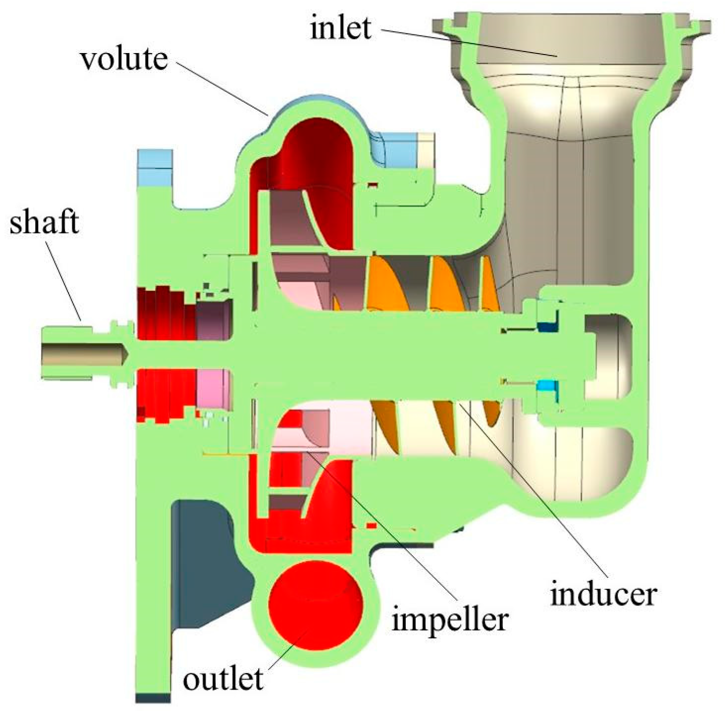
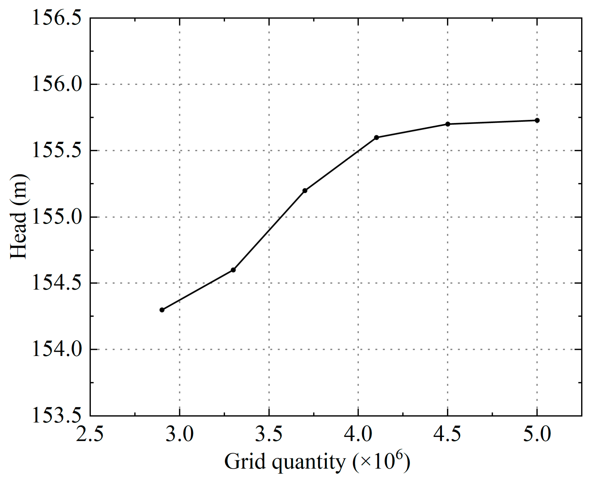
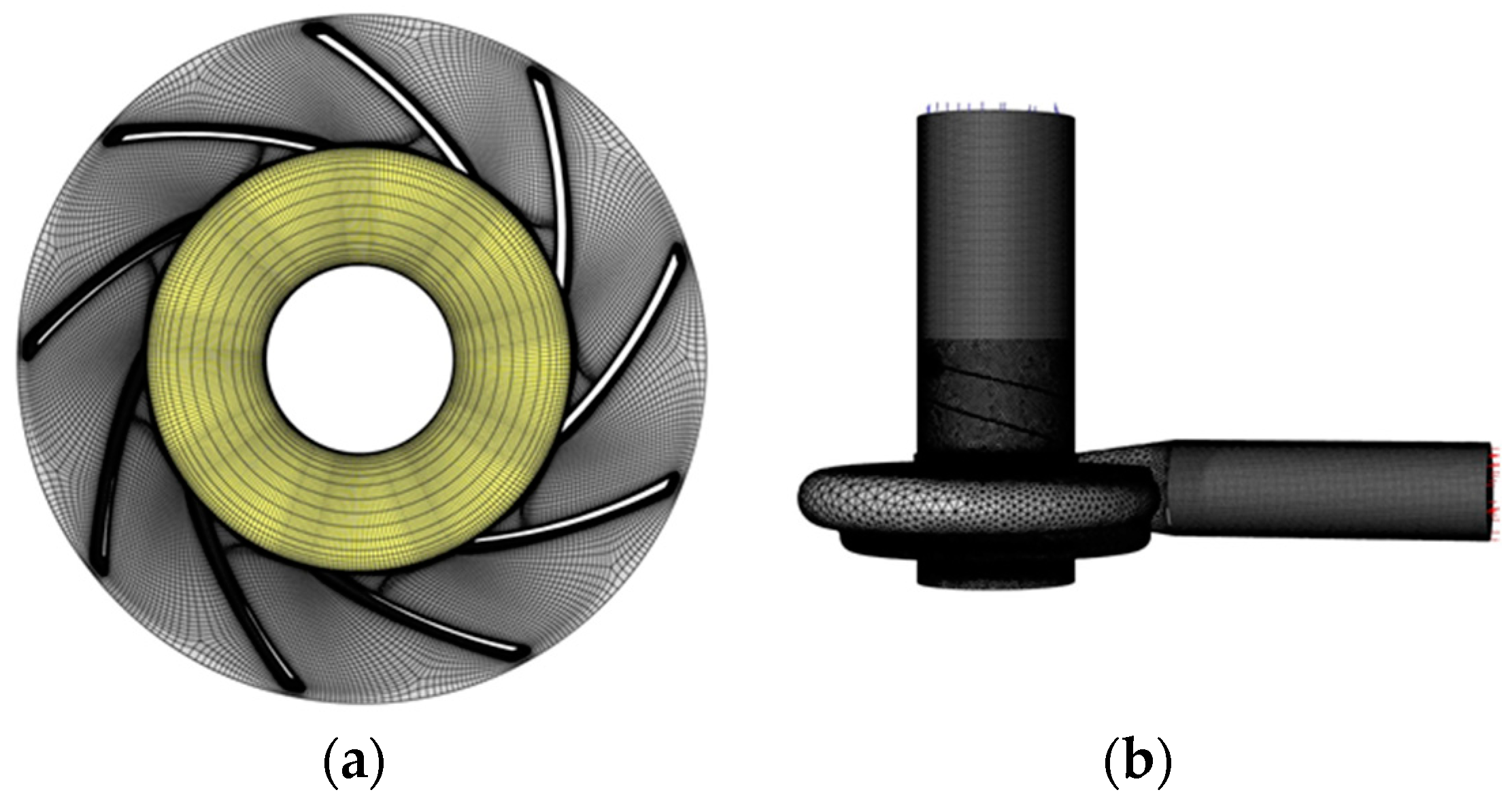
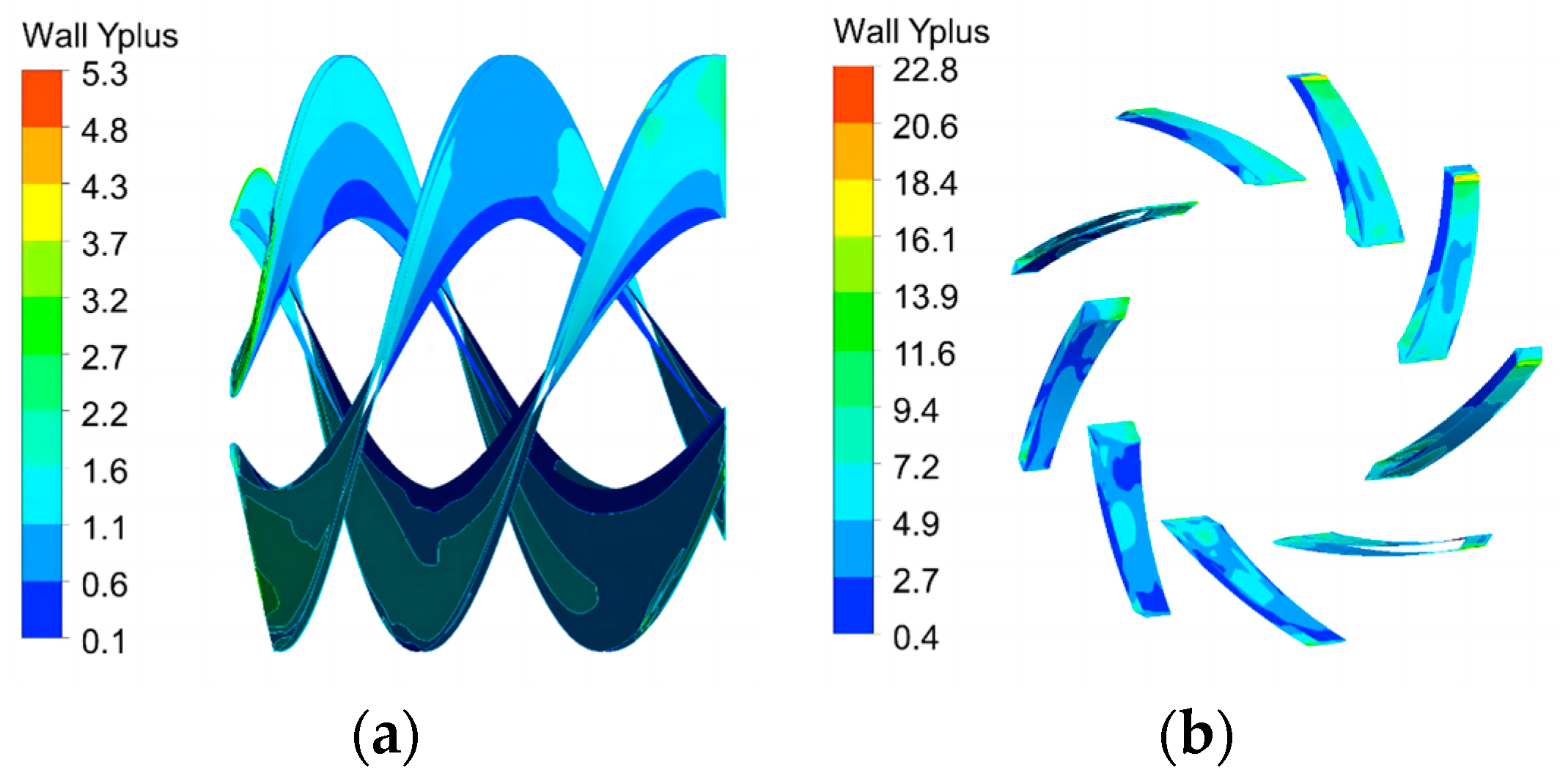
2.1. Modeling and Meshing

The aero fuel centrifugal pump studied in this paper is mainly composed of an induction impeller, centrifugal impeller, volute, drive shaft, and other components. Its three-dimensional model is shown in Figure 1 and its main design parameters are shown in Table 1.
The fluid domain was extracted from the existing three-dimensional model of the centrifugal pump. Considering the influence of the leakage of the front and rear mouth rings on pump performance and axial force, the water body between the front and rear mouth rings was included in the calculation domain. In order to obtain a stable inlet and outlet flow field, the inlet section and outlet section of the centrifugal pump are extended appropriately to obtain the inlet and outlet fluid domains. The fluid calculation domain model of the fuel centrifugal pump is shown in Figure 2.
The fluid domain of centrifugal pumps is divided by hybrid grid technology. The fluid domain of volute adopts unstructured mesh with strong adaptability and the rest of the part adopts structured mesh. In order to improve the calculation accuracy, the mesh of the blade boundary and the sealing ring is locally encrypted. The initial mesh quantity is 2.1 × 10⁶ and then the mesh density is gradually increased; the centrifugal pump head is monitored at the same time. The calculated relationship between the centrifugal pump head and the number of grids is shown in Figure 3. When the number of grids is greater than 4.0 × 10⁶, the centrifugal pump head tends to be stable and the number of grids continues to increase while the head changes little. Considering the calculation accuracy and computer performance comprehensively, the total number of all grid cells is finally determined to be 4.1 × 10⁶ and the computational domain grid is shown in Figure 4. The distribution of Y-plus values on the surface of the inducer and centrifugal impeller is shown in Figure 5, which basically meets the calculation requirements of the turbulence model.

2.2. Boundary Conditions and Solution Settings

Inner flow simulations are carried out by using the CFD code ANSYS Fluent 19.2 and the SST k-ω turbulence model is used to solve the turbulent flow field in the pump. The SST model can accurately predict the flow in a wider range, especially for the calculation of the starting point of flow separation and the size of the separation area under the condition of negative pressure gradient. When calculating the centrifugal pump model with high specific speed, it can obtain more ideal calculation results compared with other models [27,28]. The transport equations of turbulent kinetic energy k and turbulent kinetic energy dissipation rate ω are as follows:
( ρ k ) t + ρ k u i x i = x j Γ k k x j + G k Y k
( ρ ω ) t + ρ ω u i x i = x j Γ ω ω x j + G ω Y ω + D ω
where Yk and Yω, respectively, represent the dissipation term of turbulent kinetic energy caused by turbulence and the dissipation rate of turbulent kinetic energy; Γk and Γω, respectively, represent the effective diffusion coefficient of k and ω; Gk and Gω, respectively, represent k and ω generate items; and Dω denotes the cross diffusion term.
Grid interface is used to transfer data between computing domains. The wall conditions of the pump inlet and outlet wall, volute wall, front cavity wall, and back cavity wall are set as static walls. The wall boundary of the impeller blade surface and the front and rear cover plates of the pump were set as non-slip and adiabatic rotation boundaries and the standard wall function was used near the wall. The flow medium is aero fuel kerosene with a density of 780 kg/s and a dynamic viscosity of 0.003 Pa·s at room temperature. The inlet boundary is set as the pressure inlet in the static coordinate system and the pressure value is set according to the experimental measurement of the model pump. The outlet boundary is set to the outlet with different masses according to the flow condition.
The SIMPLEC solver is used for the discrete format of the system of equations. The standard format is adopted for the pressure term and the first-order upwind format is adopted for other terms such as the velocity term, turbulent viscosity coefficient, and turbulent kinetic energy term.
The multi-reference frame model (MRF) is used to simulate the coupling relationship between the rotating domain and the stationary domain. After the steady-state calculation converges, the transient slip grid (SMM) is used to solve the unsteady flow field. In the transient solution, the number of turns was set as nine and the average monitoring value of the last three turns was set as the unsteady solution value.
In order to verify the reliability of the numerical simulation results, the simulated head values under multiple flow conditions at 9000 r/min were compared with the test values, as shown in Figure 6. As can be seen from the figure, the simulated head number is basically consistent with the test value. Under the condition of large flow, the error is slightly larger and the maximum error is 6.5%, which is still within the allowable error range, indicating that the numerical calculation model is credible.

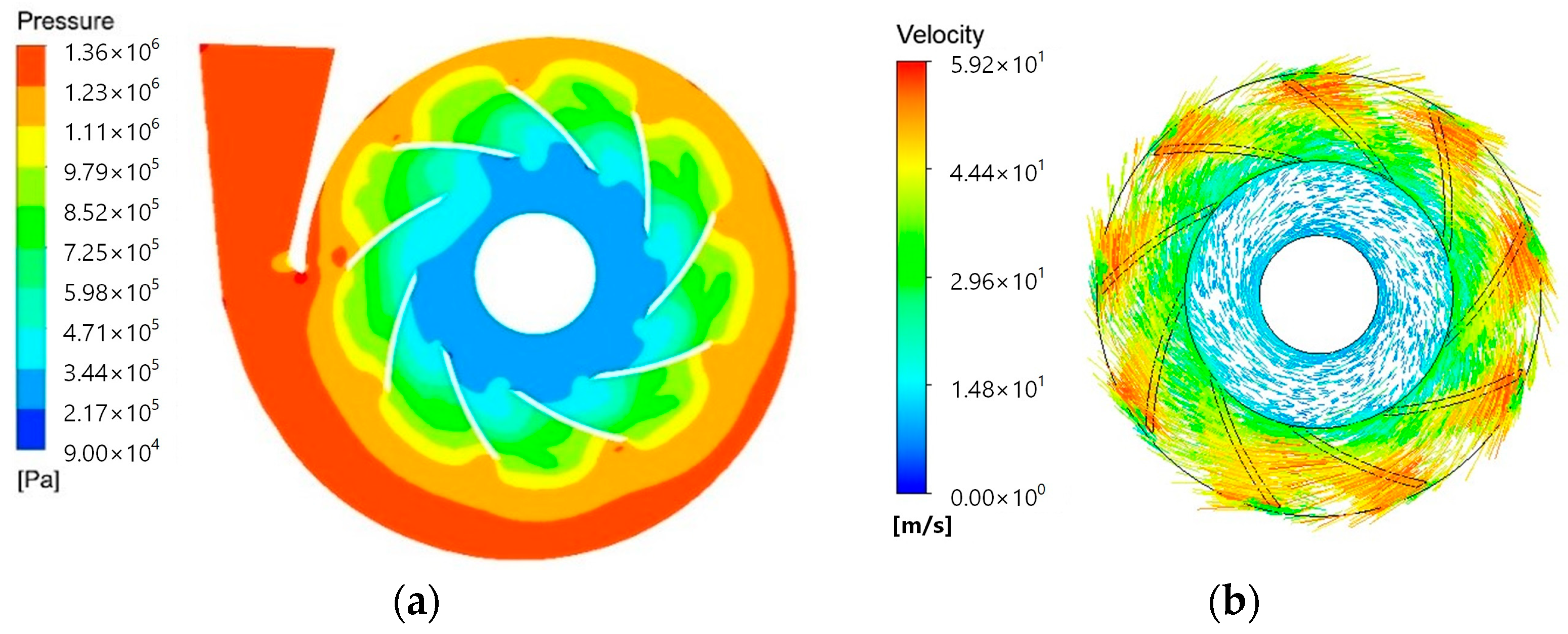
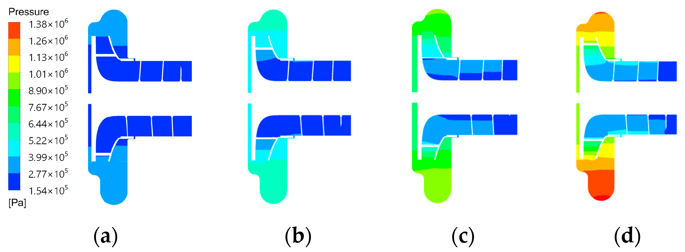
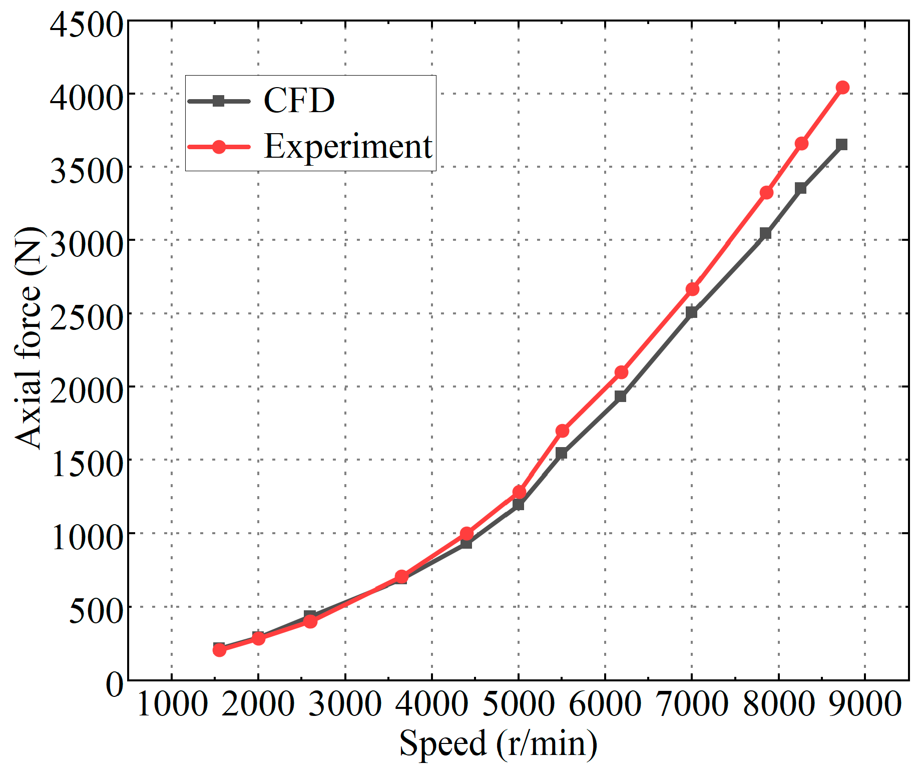
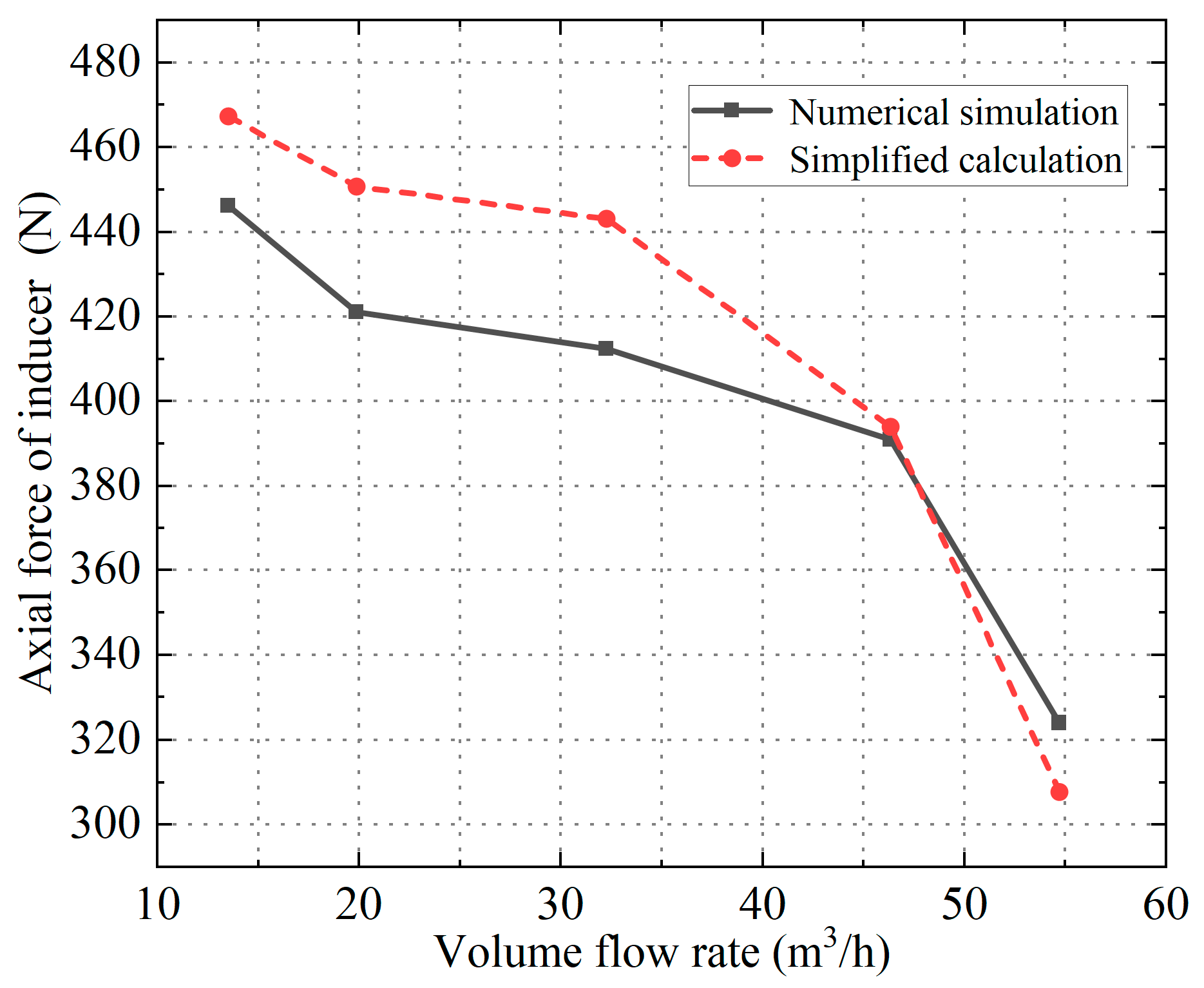
2.3. Analysis of Numerical Calculation Results

Taking the rotational speed of 9000 r/min and fuel flow rate of 54,000 L/h as an example, the steady-state calculating centrifugal blade rotation field is shown in Figure 7. As can be seen from Figure 7a, the fuel pressure in the impeller runner increases gradually along the radial direction under the work of the impeller and reaches the maximum static pressure at the volute because part of the kinetic energy is converted into static pressure energy. The flow channel pressure distribution of each blade of the impeller is more uniform and the static pressure is slightly larger near the tongue due to the influence of static and static interference.
It can be seen from Figure 7b that the fluid velocity distribution has circumferential symmetry. The fluid rotation velocity at the inlet of the centrifugal impeller is low. When it enters the impeller runner, the velocity increases gradually along the direction of the runner outlet and the velocity reaches the maximum near the impeller outlet.
Keep the inlet pressure unchanged at 0.2 MPa and change the rotational speed of the centrifugal pump. The pressure nephogram of the pump under different rotational speeds is shown in Figure 8. It can be seen from the figure that the fuel pressure increases gradually along the flow direction and reaches its maximum value at the volute. Compared with the centrifugal impeller, the pressurization capacity of the inducer is weaker and the fluid pressure in the inducer gradually increases along the radial direction; the pressurization near the hub is not obvious. The boost value of the centrifugal pump increases with the increase in rotational speed. At the same time, it can be found that the area of the impeller rear pump chamber is larger than the area of the front pump chamber and the pressure of the rear chamber of the following part of the mouth ring is much larger than the inlet pressure of the impeller, which is the main reason for the axial force of the centrifugal blade wheel.
Figure 9 shows the pressure nephogram of the front pump chamber of the fuel centrifugal pump. As can be seen from the figure, there is a radial pressure gradient for the liquid in the front and rear pump chambers. The fuel pressure also increases along the direction of the increasing radius. But at the same time, it can be found that the pressure distribution at different circumferential positions with the same radius is different. This is because the volute of the centrifugal pump converts the kinetic energy of the liquid part into static pressure energy, which makes the static pressure in the pump chamber gradually increase along the direction of impeller rotation and the pressure reaches its maximum value near the tongue.
Select all the force surfaces of the centrifugal impeller and induction wheel and calculate the axial force along the positive direction of the Z axis. The calculated axial forces on the centrifugal impeller and inducer are shown in Figure 10. It can be seen from the figure that the axial force on the centrifugal impeller and inducer increases with the increase in the centrifugal pump speed and the slope also increases obviously in the process of increasing. The axial force of the centrifugal impeller accounts for the main part of the total axial force.

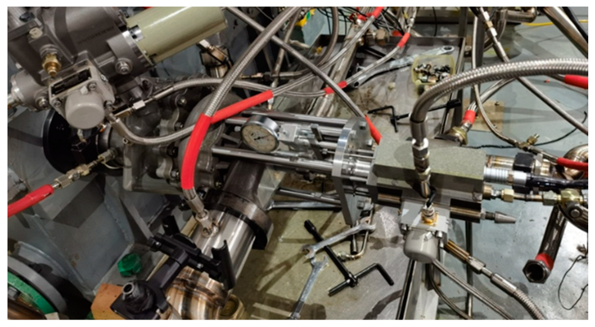
3. Axial Force Measurement Test

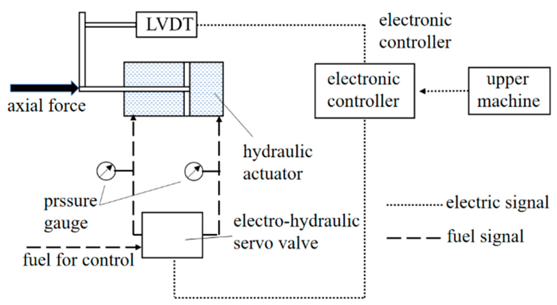
3.1. Principle of Axial Force Testing

The impeller assembly of the centrifugal pump is affected by the pressure of the fuel medium acting on the two end faces of the impeller and the impact of the fuel flow. To accurately measure the axial force of the impeller assembly, it is necessary not only to solve the influence of the high-speed rotating impeller on the measurement work but also to ensure that the impeller assembly is always in the same position in the measurement process. The principle diagram and physical diagram of the axial force measurement system of the working impeller of the fuel centrifugal pump used in the test are shown in Figure 11 and Figure 12, respectively.
The system is mainly composed of a fuel centrifugal pump, connecting sleeve, actuator, linear displacement sensor, electronic controller, and electro-hydraulic servo valve. Through the deep groove ball bearing transition between the impeller assembly and the connecting sleeve, the transmission shaft can rotate at high speed while the connecting sleeve cannot rotate, which solves the influence of high-speed rotation of the transmission shaft on the force measurement.
In order to control the axial position of the impeller component in the working process, a position servo closed-loop system is designed, which is mainly composed of the actuator (connected with the blade shaft), electro-hydraulic servo valve, linear displacement sensor, and electronic controller. After the electronic controller amplifies the feedback signal of the linear displacement sensor, the position of the actuator can be changed by adjusting the given value, as long as the given value is unchanged. Even if the actuator is interfered with by the external force, the control system can still automatically control the pressure of the two chambers of the actuator through the electro-hydraulic servo valve to keep the position of the actuator unchanged, so as to remove the coupling influence of the measurement process on the work of the centrifugal pump and ensure the accuracy of the on-line direct measurement of axial force. After calibration, the axial force can be obtained by measuring the pressure of the two cavities of the actuator, as follows:
F = P A A A P B A B
where PA and PB are, respectively, the oil pressure in the left and right cavities of the actuator, Pa, and AA and AB are, respectively, the effective acting area of the oil pressure in two cavities, m2.

3.2. Analysis of Test Results

In order to obtain axial force data at different speeds, the outlet throttling state and inlet pressure of the centrifugal pump were kept unchanged during the test and the speed was continuously increased from zero until it reached the maximum speed. The flow, fuel outlet pressure, and axial force values under different speed conditions were measured and the numerical simulation values were compared with the test values, as shown in Figure 13. As can be seen from the figure, the variation trend of the simulation value and the test value is roughly the same. Under the condition of low rotating speed, the simulation value is slightly larger than the test value, while under the condition of high rotating speed, the simulation value is smaller than the test value. The maximum error of 9.7% is allowed in the calculation of axial force.

4. Theoretical Calculation Formula of Axial Force

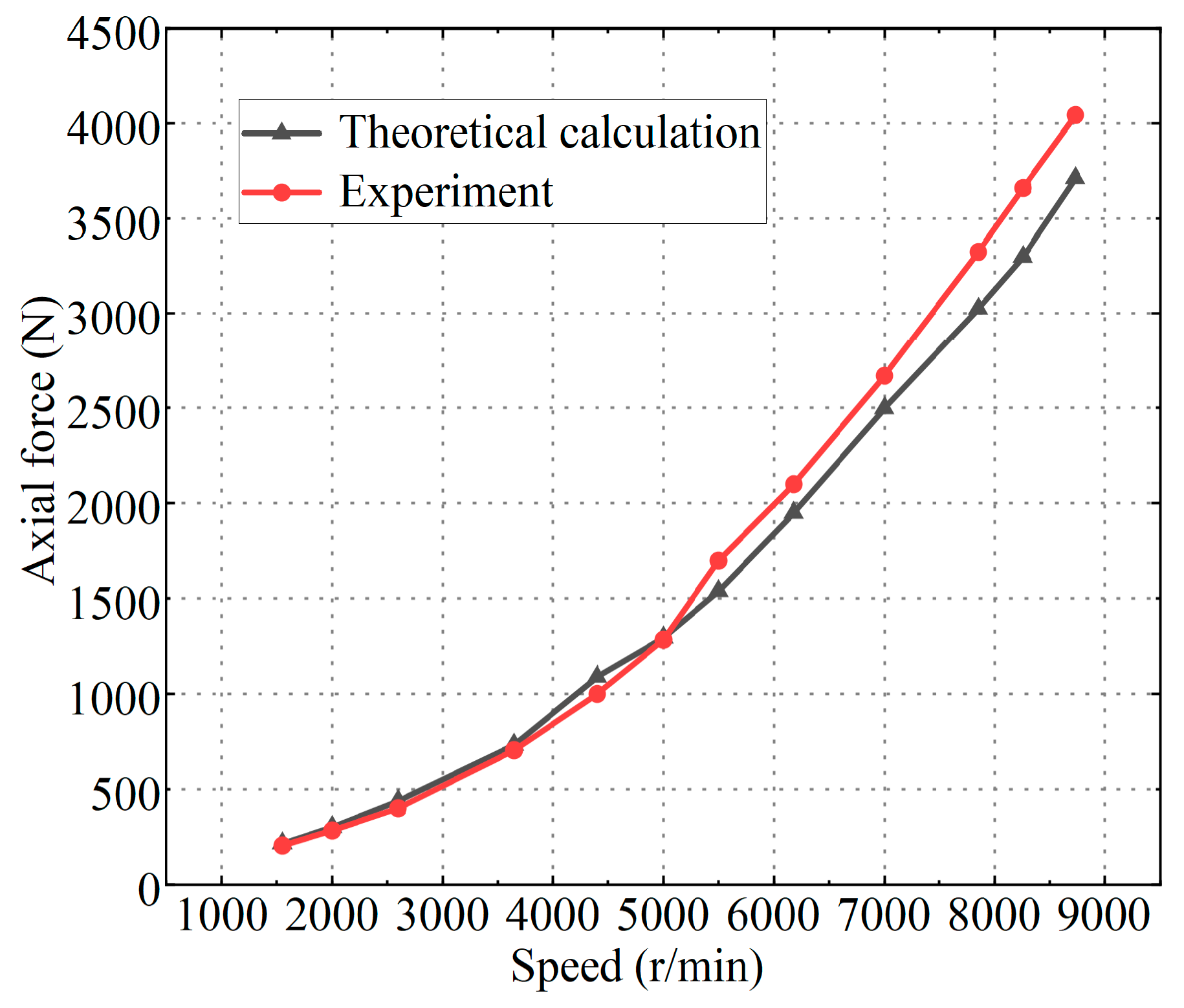
4.1. Theoretical Formula Calculation

The axial force of a centrifugal pump is mainly composed of cover plate force and dynamic reaction force [29]. For the centrifugal pump studied in this paper, because the oil inlet and outlet are radial, the axial force caused by the dynamic reaction can be ignored. For the closed impeller, on the one hand, the front and rear cover plates of the impeller are asymmetrical, that is, the front cover plates are not covered in the suction eyes. On the other hand, the rotation of the front and rear cover plates of the impeller will drive the rotation of the liquid in the front and rear cavities. It is generally believed that the liquid pressure in the side cavity is distributed in a parabolic pattern [20]. Without considering the leakage of the front and rear mouth rings, the hydraulic force on the rear cover plate is subtracted from the hydraulic force on the front cover plate and then the pressure remaining from the suction pressure is subtracted to generate an axial force and the direction is directed toward the inlet of the impeller. According to the theoretical head of the centrifugal pump, the axial surface velocity of the impeller inlet and outlet section is assumed to be equal, and the inlet prerotation is ignored. Then, according to the Bernoulli equation and other relevant theories, the intermediate process is omitted and the axial force (T) of the impeller cover plate can be deduced, as follows:
T = π ρ g ( R m 2 R h 2 ) H p ω 2 8 g ( R 2 2 R m 2 + R h 2 2 )
where Rm and Rh are, respectively, the radius of mouth ring and hub, m; Hp is potential lift, m; R2 is the outlet radius of the impeller, m; and ω is the angular velocity of impeller rotation, rad/s.
Taking the centrifugal pump speed of 8500 r/min and fuel flow rate of 24 m3/h as an example, the axial force of the impeller component calculated by Formula (4) is 2742 N, which has a large error with the 4045 N measured by the test. This is because the formula ignores the pump cavity leakage and other factors and the default impeller front and rear hub diameter is the same and cannot calculate the axial force on the inducer blade, resulting in the use of this formula to calculate the axial force of the fuel centrifugal pump studied in this paper is not accurate.

4.2. Calculation Method Modification

Referring to experimental data and simulation results, the pressure correction coefficient was introduced to correct the calculation formula of pressure distribution in the pump chamber [8,30]. The formula for calculating the static pressure distribution of the cover plate can be modified, as follows:
p = k 1 p 2 k 2 ρ u 2 2 8 ( 1 R 2 R 2 2 )
where p2 is the static pressure at the impeller outlet, Pa; k1 is the correction coefficient of static pressure term in the rear pump chamber; and k2 is the correction factor of pressure drop in the rear pump chamber.
Then, the liquid pressure of the rear pump chamber on the rear cover plate is, as follows:
F 1 = π ( R 2 2 R h 1 2 ) k 1 p 2 k 2 ρ ω 2 8 ( R 2 2 R h 1 2 2 )
where Rh1 is the radius of the driving shaft, m, and R2 is the impeller radius, m.
Similarly, the pressure of the front pump chamber on the front cover plate of the impeller is, as follows:
F 2 = π ( R 2 2 R m 2 ) k 3 p 2 k 4 ρ ω 2 8 ( R 2 2 R m 2 2 )
where Rm is the radius of the mouth ring; k3 is the correction coefficient of the static pressure item of the front pump chamber; and k4 is the pressure drop correction factor of the front pump chamber.
The multiple linear regression function in Matlab 2016 is used to fit the pressure distribution curve of the pump chamber and the static pressure correction coefficient and pressure drop correction coefficient of the front and rear pump chamber are obtained, as shown in Table 2.
Let the static pressure at the outlet of the inducer (an inlet of the centrifugal impeller) be p3 and the axial force on the inducer can be approximated as the product of the static pressure difference at both ends of the inducer and the cross-sectional area of the impeller runner. In order to verify the accuracy of the simplified calculation method, under different flow conditions at rated speed, the axial force on the inducer impeller surface was directly integrated by the post-processing software and the axial force calculated by the pressure difference at the inducer inlet and outlet surface was compared, as shown in Figure 14. As can be seen from the figure, at a certain speed, the axial force of the induction wheel gradually decreases with the increase in fuel flow. When the flow rate increases from 13 m3/h to 55 m3/h, the axial force induction wheel obtained by numerical simulation decreases from 446 N to 329 N, which is reduced by 117 N. At the same time, it can be seen that the induction wheel axial force obtained by the simplified calculation method is basically consistent with the numerical simulation value and the maximum error is 6.9%. Thus, the induction wheel axial force can be calculated more accurately by this method.
The axial force (F3) of the suction side of the impeller mouth ring minus the axial force of the induction wheel is defined as follows:
F 3 = π p 2 ( R m 2 R h 2 2 ) π ( p 3 p 1 ) ( R m 2 R h 2 2 ) = π p 1 ( R m 2 R h 2 2 )
where p1 is the static pressure at the pump inlet, Pa, and Rh2 is the hub radius, m.
According to the above analysis, the modified total axial force (T′) of the impeller assembly of the centrifugal pump is as follows:
T = F 1 F 2 F 3
The revised formula is used to calculate the axial force of the fuel centrifugal pump at different speeds and compare it with the test value, as shown in Figure 15. As can be seen from the figure, the modified theoretical calculated value is consistent with the experimental value and the maximum error is 9.88%. The modified formula can predict the axial force of the impeller assembly of the fuel centrifugal pump well.

5. Conclusions

In this paper, taking an aero fuel centrifugal pump as the research object, the axial force of the impeller component was calculated by numerical simulation and experimental methods, respectively, to verify the accuracy of numerical calculation. Combined with the simulation and experimental results, the theoretical calculation formula of axial force was modified.
The static pressure in the pump chamber gradually increases along the rotation direction of the impeller because the volute of the centrifugal pump converts the kinetic energy of the liquid part into static pressure energy. Through numerical simulation, it is found that the pressure of the front and rear pump chambers of the fuel centrifugal pump presents a circumferential uneven distribution under the influence of dynamic and static interference. Moreover, the area of the rear pump chamber is larger than that of the front pump chamber and the pressure of the rear chamber below the mouth ring is far above the inlet pressure of the impeller, which is the primary reason for the axial force of the impeller in the centrifugal pump.
The position servo force measuring system used in the test avoids the influence of high-speed rotation of the transmission shaft on the force measurement, relieves the coupling influence of the measurement process on the work of the pump, and ensures the accuracy of the online direct measurement of the axial force of the working impeller in the fuel centrifugal pump. By comparing the numerical results with the experimental values, the following conclusions are drawn:
  • The axial force of the centrifugal impeller accounts for the main part of the total axial force, while the axial force of the induction wheel is relatively small due to its weak pressurization ability. Under the condition of constant outlet throttling state, the axial force of the fuel centrifugal pump increases with the increase in the rotational speed and the slope of the curve also increases obviously in the process of increasing;
  • The variation trend of the simulated axial force obtained by the numerical simulation method is roughly the same as that of the experimental value and the maximum error is 9.7%. The simulation method can accurately predict the axial force of an aero fuel centrifugal pump;
  • The axial force of the centrifugal pump calculated by the traditional theoretical formula has a large error, while the error between the calculated value obtained by the modified formula and the experimental value is within 9.88%, indicating that the modified formula can accurately calculate the axial force of the fuel centrifugal pump.

Author Contributions

The contributions of all the authors to this manuscript are as follows: Conceptualization, S.Y. and Y.K.; methodology, S.Y.; software, S.Y. and X.L.; validation, S.Y., Y.K. and L.X.; formal analysis, S.Y.; writing—original draft preparation, S.Y. and L.X.; writing—review and editing, S.Y. and X.L.; supervision, Z.Y.; project administration, Z.Y. All authors have read and agreed to the published version of the manuscript.

Funding

This manuscript was funded by the National Natural Science Foundation of China, grant number 62373185.

Institutional Review Board Statement

Not applicable.

Informed Consent Statement

Not applicable.

Data Availability Statement

The data presented in this study are available on request from the corresponding author.

Acknowledgments

Acknowledgements to AECC Guizhou Honglin Aero-Engine Control Technology Co., Ltd., for support of the test site and equipment for this research subject.

Conflicts of Interest

Author Shebin Yan was employed by AECC Guizhou Honglin Aero-Engine Control Technology Co., Ltd. Author Yinhui Kan was employed by AVIC Jincheng Nanjing Engineering Institute of Aircraft System. The remaining authors declare that the research was conducted in the absence of any commercial or financial relationships that could be construed as a potential conflict of interest.

References

  1. Zhang, N.; Gao, B.; Li, Z.; Ni, D.; Jiang, Q. Unsteady flow structure and its evolution in a low specific speed centrifugal pump measured by PIV. Exp. Therm. Fluid Sci. 2018, 9, 133–144. [Google Scholar] [CrossRef]
  2. Li, W.G. Effects of viscosity on turbine mode performance and flow of a low specific speed centrifugal pump. Appl. Math. Model. 2016, 40, 904–926. [Google Scholar] [CrossRef]
  3. Jafarzadeh, B.; Hajari, A.; Alishahi, M.; Akbari, M. The flow simulation of a low-specific-speed high-speed centrifugal pump. Appl. Math. Model. 2011, 35, 242–249. [Google Scholar] [CrossRef]
  4. Hou, H.; Zhang, Y.; Li, Z. A numerically research on energy loss evaluation in a centrifugal pump system based on local entropy production method. Therm. Sci. 2017, 21, 1287–1299. [Google Scholar] [CrossRef]
  5. Wang, C.; Shi, W.; Wang, X.; Jiang, X.; Yang, Y.; Li, W.; Zhou, L. Optimal design of multistage centrifugal pump based on the combined energy loss model and computational fluid dynamics. Appl. Energy 2017, 187, 10–26. [Google Scholar] [CrossRef]
  6. Zemanová, L.; Rudolf, P.; Zubík, P. Experimental investigation of flow inside the back-sidewall gaps of centrifugal pump and its impact on axial thrust. IOP Conf. Ser. Earth Environ. Sci. 2022, 1079, 012037. [Google Scholar] [CrossRef]
  7. Tan, M.; Yuan, S.; Liu, H.; Wang, Y.; Wang, K. Numerical research on performance prediction for centrifugal pumps. Chin. J. Mech. Eng. 2010, 23, 21–26. [Google Scholar] [CrossRef]
  8. Kalinichenko, P.; Shepil, O.; Velikodnyj, E. Effective ways of axial relief of a stage of the centrifugal pump and the compressor. Compress. Power Eng. Ind. 2007, 16, 79–81. [Google Scholar]
  9. Cheah, K.; Lee, T.; Winoto, S.; Zhao, Z. Numerical flow simulation in a centrifugal pump at design and off-design conditions. Int. J. Rotating Mach. 2007, 115, 342–350. [Google Scholar] [CrossRef]
  10. Huang, D.; Zhuang, Y.; Cai, R. A computational method for cavitational flows based on energy conservation. Proc. Inst. Mech. Eng. J. Mech. Eng. Sci. 2007, 221, 1333–1338. [Google Scholar] [CrossRef]
  11. Guo, M.; Liu, S.; Tang, X.L. Evaluation of shaft forces in a vertical canned motor through local hydraulic loss analysis. Adv. Mech. Eng. 2018, 3, 1–20. [Google Scholar] [CrossRef]
  12. Zhou, L.; Shi, W.; Li, W.; Agarwal, R. Numerical and experimental study of axial force and hydraulic performance in a deep-well centrifugal pump with different impeller rear shroud radius. J. Fluids Eng. 2013, 135, 104501. [Google Scholar] [CrossRef]
  13. Wang, C.; Shi, W.; Zhang, L. Calculation formula optimization and effect of ring clearance on axial force of multistage pump. Math. Probl. Engineering 2013, 2013, 749375. [Google Scholar] [CrossRef]
  14. Han, W.; Maa, W.; Li, R.; Li, Q. The numerical analysis of radial thrust and axial thrust in the screw centrifugal pump. Procedia Eng. 2012, 31, 176–181. [Google Scholar] [CrossRef]
  15. Pehlivan, H.; Parlak, Z. Investigation of parameters affecting axial load in an end suction centrifugal pump by numerical analysis. Appl. Fluid Mech. 2019, 12, 1615–1627. [Google Scholar] [CrossRef]
  16. Gantar, M.; Florjancic, D.; Sirok, B. Hydraulic axial thrust in multistage pumps-origins and solutions. J. Fluids Eng. 2002, 124, 336–341. [Google Scholar] [CrossRef]
  17. Mary, B.; Cerru, F. Axial force modelling and measurement in a single stage centrifugal pump. In Proceedings of the European Conference on Turbomachinery Fluid Dynamics and Thermodynamics, Lausanne Switzerland, 8–12 April 2019. [Google Scholar]
  18. Hernandez-Solis, A.; Carlsson, F. Diagnosis of submersible centrifugal pumps: A motor current and power signature approaches. Epe J. Power Electron. Drives 2010, 20, 58–64. [Google Scholar] [CrossRef]
  19. Kim, P.; Bae, S.; Seok, J. Resonant behaviors of a nonlinear cantilever beam with tip mass subject to an axial force and electrostatic excitation. Int. J. Mech. Sci. 2012, 64, 232–257. [Google Scholar] [CrossRef]
  20. Schaefer, S.; Olson, E. Experimental evaluation of axial thrust in pumps. World Pumps. 1999, 393, 34–37. [Google Scholar]
  21. Babayigit, O.; Ozgoren, M.; Aksoy, M.; Kocaaslan, O. Experimental and CFD investigation of a multistage centrifugal pump including leakages and balance holes. Desalin. Water Treat. 2017, 67, 28–40. [Google Scholar] [CrossRef]
  22. Dong, W.; Chu, W.; Liu, Z.L. Influences of the diameter of the balance hole on the flow characteristics in the hub cavity of the centrifugal pump. J. Hydrodyn. 2019, 31, 1060–1068. [Google Scholar] [CrossRef]
  23. Zhu, D.; Yao, Z.; Yang, W.; Liu, W. Optimization design for reducing the axial force of a vaned mixed-flow pump. Eng. Appl. Comput. Fluid Mech. 2020, 14, 882–896. [Google Scholar] [CrossRef]
  24. Cheng, X.; Chang, Z.; Jiang, Y. Study on the influence of the specific area of balance hole on cavitation performance of high-speed centrifugal pump. J. Mech. Sci. Technol. 2020, 34, 3325–3334. [Google Scholar] [CrossRef]
  25. Xia, B.; Kong, F.; Zhang, H. Investigation of axial thrust deviation between the theory and experiment for high-speed mine submersible pump. Adv. Mech. Eng. 2018, 10, 754356344. [Google Scholar] [CrossRef]
  26. Bruurs, K.; Van, B.; Van, M.S. Axial thrust prediction for a multi-stage centrifugal pump. In Proceedings of the Fluids Engineering Division Summer Meeting: American Society of Mechanical Engineers, Waikoloa, HI, USA, 30 July–3 August 2017. [Google Scholar]
  27. Spalart, P.; Shur, M. On the sensitization of turbulence models to rotation and curvature. Aerosp. Sci. Technol. 1997, 1, 297–302. [Google Scholar] [CrossRef]
  28. Feng, J.; Benra, F.; Dohmen, H. Application of different turbulence models in unsteady flow simulations of a radial diffuser pump. Forsch. Ingenieurwes. 2010, 3, 123–133. [Google Scholar] [CrossRef]
  29. Zhao, J.J.; Mu, J.G.; Zheng, S.H.; Lu, H.Q.; Wang, H. The impact of balance hole radial position of centrifugal pump on axial force and external characteristics. Appl. Mech. Mater. 2012, 130, 1691–1695. [Google Scholar] [CrossRef]
  30. Kalinichenko, P.; Suprun, A. Effective modes of axial balancing of centrifugal pump rotor. Procedia Eng. 2012, 39, 111–118. [Google Scholar] [CrossRef]
Figure 1. Three-dimensional model of fuel centrifugal.
Applsci 14 04313 g001
Figure 2. Fluid calculation domain model of the fuel centrifugal pump.
Applsci 14 04313 g002
Figure 3. Grid independence verification.
Applsci 14 04313 g003
Figure 4. Hybrid mesh of the computational domain: (a) centrifugal impeller grid and (b) centrifugal pump integral grid.
Applsci 14 04313 g004
Figure 5. Y-plus of the inducer and impeller blades surface: (a) inducer and (b) impeller.
Applsci 14 04313 g005
Figure 6. Comparison of performance curves between experiment and CFD.
Applsci 14 04313 g006
Figure 7. Pressure nephogram and velocity vector of the impeller section: (a) pressure nephogram and (b) velocity vector.
Applsci 14 04313 g007
Figure 8. Y-Z cross-section pressure nephogram centrifugal pump under different speed conditions: (a) 2600 r/min; (b) 5000 r/min; (c) 7000 r/min; and (d) 8500 r/min.
Applsci 14 04313 g008
Figure 9. Pressure nephogram of the front and rear pump chamber of the fuel centrifugal pump: (a) front pump chamber and (b) rear pump chamber.
Applsci 14 04313 g009
Figure 10. Relationship between axial force and speed of centrifugal pump.
Applsci 14 04313 g010
Figure 11. Fuel centrifugal pump axial force test system schematic diagram.
Applsci 14 04313 g011
Figure 12. Fuel centrifugal pump axial force test device physical diagram.
Applsci 14 04313 g012
Figure 13. Comparison of the simulation value and experiment value of axial force.
Applsci 14 04313 g013
Figure 14. Relationship between the axial force of the induction wheel and volume flow rate.
Applsci 14 04313 g014
Figure 15. Comparison of theoretical and experimental values of axial force after modification.
Applsci 14 04313 g015
Table 1. Basic parameters of a fuel centrifugal pump.
ParametersValue
Rated speed/(r/min)9000
Maximum fuel flow/(kg/h)50,000
Number of blades3 (Inducer), 9 (Impeller)
Inlet diameter of impeller/mm70.3
Outer diameter of impeller/mm115
Table 2. Correction factor of the pressure in the front and rear pump chamber.
k1k2k3k4
1.0160.7461.0481.435
Disclaimer/Publisher’s Note: The statements, opinions and data contained in all publications are solely those of the individual author(s) and contributor(s) and not of MDPI and/or the editor(s). MDPI and/or the editor(s) disclaim responsibility for any injury to people or property resulting from any ideas, methods, instructions or products referred to in the content.

