1. Introduction
Augmented reality (AR) technology, previously considered a vision of the future, is now increasingly integrated into daily activities, particularly through its synergy with smartphones. This integration offers high-performance and cost-effective solutions, significantly enhancing the utility of AR in daily life [
1]. The adoption of smartphone cameras for spatial tracking with centimeter-level accuracy has substantially advanced AR applications, especially in settings with spatial constraints. Although the potential of global navigation satellite systems (GNSS) and magnetic digital compasses to broaden AR’s applicability has been recognized [
2], their precision limitation often leads to the adoption of QR codes and local coordinate systems in contexts requiring precise locational data, such as indoor navigation in museums or malls [
3]. These methods are preferred for their reliability and the ability to easily implement them without the complexities of calibration or reliance on satellite signals, which are often unreliable indoors or in dense urban environments. Furthermore, high-precision, camera-based spatial tracking is crucial for effective navigation in urban spaces, as it offers accurate positioning and perception of the environments of complex urban areas [
4,
5].
In the context of traditional location-based services (LBS), GNSS has been crucial, particularly in enhancing automotive navigation and mobile mapping [
6]. However, the accuracy of GNSS can vary significantly, typically between 2 and 6 m under optimal conditions [
7]. It is considerably less effective in indoor and underground environments due to electromagnetic interference and signal reception challenges. Although Bluetooth and wireless personal area network (WPAN) beacons have been developed to enhance indoor IT services [
8,
9,
10,
11,
12], the comprehensive and seamless integration of these technologies across extensive and interconnected indoor spaces remains an unfulfilled goal.
The paper proposes a novel framework designed to surmount two primary obstacles to advancing indoor AR navigation technology: the effective navigation of extensive absolute coordinate spaces and the minimization of cumulative positioning errors in camera-based tracking systems. The framework utilizes visual-inertial odometry (VIO) [
13,
14,
15], complemented by location reference image markers and a transformation from local-to-global spatial coordinates, to boost accuracy and reliability across broad coordinate spaces. By integrating a global spatial coordinate system, we enable the use of geofencing, a technology well-established in outdoor LBS [
16], for indoor environments as well. We demonstrate the effectiveness and practicality of our framework through application development and testing in the Akita University Mineral Industry Museum (Tegata-Osawa, Akita, Japan) [
17]. This research differentiates itself by offering a synergistic combination of VIO with image-based calibration and integrating a global spatial coordinate system, laying the groundwork for future advancements in developing practical indoor AR navigation systems.
The present paper is structured as follows:
Section 2 reviews the related work to position our research.
Section 3 describes the indoor AR navigation framework, focusing on calibration with camera-based reference image recognition and spatial tracking.
Section 4 explores the practice of indoor AR positioning in a real-world context, including the recognition of location reference images and the management of spatial tracking errors.
Section 5 details the implementation of the navigation service, focusing on geofencing designs.
Section 6 demonstrates a field test conducted at the Akita University Mining Museum.
Section 7 discusses the results, challenges, and limitations. Finally,
Section 8 concludes the paper by summarizing the study’s contributions and proposing future research directions.
2. Related Work
2.1. Indoor AR Navigation Technologies
According to Cheliotis et al.’s survey [
18], AR has been explored as a method of spatial navigation, both indoors and outdoors, over the past two decades. Research interest has risen significantly since 2010, as the ubiquity of smartphones and similar handheld devices has lowered the technical knowledge threshold for AR application development. More than half of the 60 publications that can be applied in indoor environments use general mobile devices, while others use custom devices or dedicated AR devices like head-mount displays (HMD). Liu et al. [
19] proposed an indoor navigation developed on HoloLens, focusing on the use of virtual semantic landmarks. Their follow-up research introduces a general framework using mixed-reality technology for indoor navigation assistance for user studies [
20], which is mainly designed for HMD. However, we argue that the current ubiquity of hand-held devices like smartphones will continue to exist, and it still takes time for HMD to achieve the same popularity. Thus, we chose smartphones as our main target device for this research.
Positioning and view alignment are two of the essential components in AR navigation. Technologies used for positioning in indoor navigation mainly include Wi-Fi, Bluetooth, inertial sensors, and cameras [
8,
9,
10,
11,
12]. View alignment overlays directions and other visualized information for navigation on the view of the real world using cameras and sensors. The two components are often developed separately. For example, ARBIN, developed by Huang et al. [
21], is designed to enhance navigation in large indoor spaces like hospitals, airports, and train stations, with AR used for display directions and navigation clues, while positioning depends on Bluetooth Low Energy (BLE) beacons. However, such approaches depend on additional infrastructures installed in the building. The cost and accessibility of the infrastructure can hinder the practical application of indoor AR navigation.
Faced with the challenge, infrastructure-free indoor navigation technologies are being developed. Chehreghan et al. [
22] proposed a solution based on a fusion of smartphone sensors, considering texting and pocket-carrying modes, but AR applications are not in the scope of this research, and smartphone cameras are not utilized. As cameras can be used for both positioning and view alignment, it is natural to consider utilizing the HHD’s camera as the main sensor (often associated with other built-in sensors) for low-cost solutions. QR code-based AR applications [
3] can be considered a typical example of such solutions, and the image marker is not necessarily restricted to QR codes. Mulloni et al. developed an indoor navigation system with mobile phone cameras by detecting unobtrusive fiduciary markers [
23] before the emergence of contemporary smartphones. However, setting up and maintaining additional markers like QR codes can still be labor-intensive and not purely infrastructure-free, which is pursued by this research.
2.2. Image-Tracking-Based Indoor Navigation
Khan et al. [
24] pointed out that, unlike sensor-based or network-based methods, vision-based methods provide low-cost and easy-to-use solutions for indoor navigation. The technologies that originated in the field of robotics, such as Visual Inertial Odometry (VIO) [
13,
14] and camera-based Simultaneous Localization and Mapping (SLAM) [
25], have become commonly available in smartphones [
15] and other consumer electronics. VIO combines data from visual sources (like cameras) and inertial measurement units (IMUs, commonly embedded in smartphones) to estimate the position and orientation of a device relative to its environment. The integration of such technologies in smartphones has boosted the precision of AR applications without relying on external references like GPS or beacons. Komianos [
26] also indicated that AR is easy to employ in museums compared to Virtual Reality (VR) and Mixed Reality (MR) because it is mostly based on the Bring Your Own Device (BYOD) concept as it reduces costs and is easier for users to handle their own device. The survey by Shewail et al. [
27] revealed that, for the purpose of indoor tracking, communication technology-based tracking can be faulty for applications that need accurate tracking and registration, while image-based tracking can be more accurate and reliable. However, they also pointed out the scalability problems of image-tracking-based solutions.
Rubio-Sandoval et al. [
28] proposed a methodology for smartphone-based indoor navigation that integrates AR and the Semantic Web. Their implementation utilizes the Unity3D engine’s AR Foundation framework to integrate smartphones’ AR frameworks to realize positioning. Fajrianti et al. [
29] developed an indoor navigation system with Visual SLAM based on the smartphone camera and gyroscope. The implementations in both researches still need additional QR codes for location initialization, which we consider unnecessary because the reference markers can be any pre-defined image as long as a smartphone camera can track it.
AR applications commonly place contents close to the initial location, as accumulative positioning errors may disrupt the user experience when the distance to the reference marker becomes longer. We consider this problem a main obstacle to practical image-tracking-based indoor navigation applications, as the users are supposed to move away from the initial marker to the destinations. Fajrianti et al. [
29] discussed navigation accuracy from the viewpoint of the relationship between the navigation task success rate and smartphone angles. However, the numerical positioning error and its relation to the moving distance are not mentioned. Rubio-Sandoval et al. [
28] also analyzed the accumulative positioning error as distance offset in different buildings and tasks. The error has a positive relation with the navigation distance but lacks consistency. The authors considered the illumination conditions to be the cause, but they did not come up with solutions from the application side. We suggest that periodical calibration by tracking reference markers can be a feasible solution.
2.3. Geofencing in Indoor Navigation
Geofencing uses positioning technology like GPS to create a virtual geographic boundary, enabling software to trigger a response when a mobile device enters or leaves a particular area [
16]. Geofencing is a mature technology in LBS commonly used for location-based notification, wayfinding, and navigation. It is also utilized in research like behavioral studies [
30]. In the indoor environment, as GPS is generally unavailable, Wi-Fi/Bluetooth beacons and RFID tags are often used for positioning. Common use cases include proximity marketing [
31], behavior monitoring [
32], and enhanced user experience. For example, ExhibitXplorer, developed by Ivanov [
33], uses a combination of geofencing, artificial intelligence (AI), and microservices to provide dynamic, personalized content to museum visitors. However, these implementations usually depend on infrastructures like Wi-Fi and/or beacons for positioning, and their requirement for location accuracy is much lower than an AR application. This is because the purpose of geofencing in our proposed framework differs from roughly detecting enter/leave behaviors. For instance, geofences triggering direction display updates at waypoints may require accuracy under one meter to avoid malfunction or misunderstanding. Furthermore, these geofences are triggered by the virtual location of the direction arrow displayed in the AR interface instead of the smartphone’s actual location for a more appropriate user experience. Thus, the strategies of geofence placement, sizes, and error tolerance can be different from those using different positioning technologies.
3. Indoor AR Navigation Framework Based on Geofencing and Image-Tracking
In this section, we introduce an essential framework for indoor AR navigation that leverages global coordinate systems to facilitate navigation in extensive environments, moving beyond the limitations of traditional systems that are confined to small, localized areas. This approach circumvents the need for conventional infrastructure like BLE by utilizing high-accuracy location services, which depend on the image recognition of location markers and tracking of planes with smartphone cameras. Furthermore, this framework incorporates geofencing and a strategy for adjusting cumulative errors by addressing a notable void in the research on indoor AR navigation. Previous studies have mainly focused on elemental issues, neglecting the development of an all-encompassing framework that ensures the practical applicability of smartphone-based indoor AR navigation. Our proposition fills this critical gap by offering a substantial and integrated solution. Furthermore, this section elaborates on the operational overview of the proposed indoor AR navigation system, setting the stage for the subsequent sections that will discuss the challenges and solutions involved in realizing such functionality.
3.1. Overview of the Elemental Sessions in the Framework
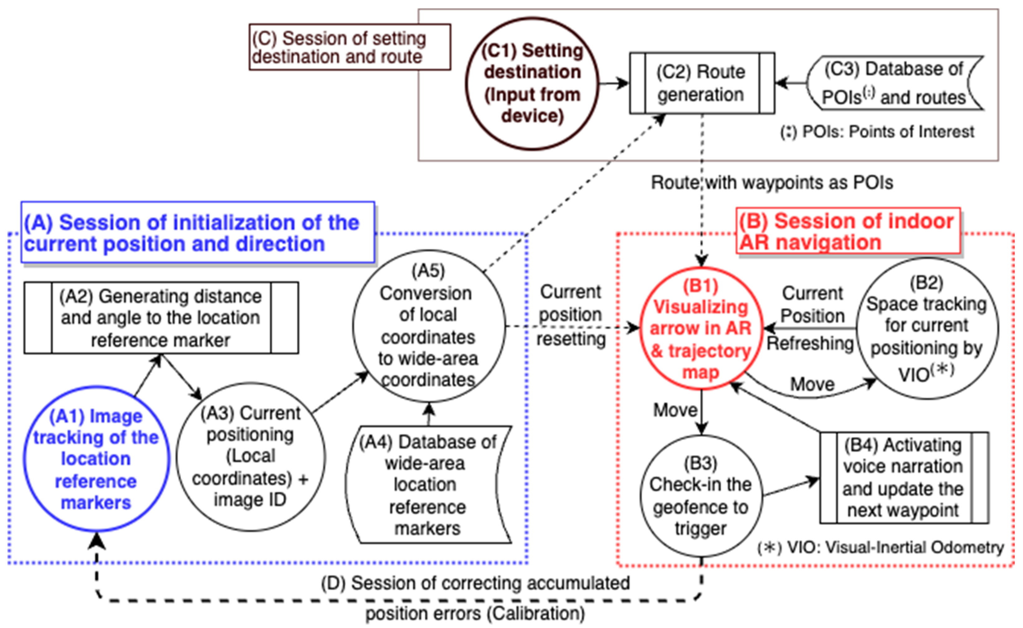
Figure 1 presents an overview of the four elemental sessions of the proposed indoor AR navigation framework, which are described as follows:
(A) Session of initialization of the current position and direction: When starting the AR navigation, the position and orientation of the smartphone are initialized using image-tracking of the location reference markers (A1) with a database of wide-area location reference markers (A4) that have been prepared in advance. This process uses the image-tracking functions of the ARWorldTrackingConfiguration Class in the ARKit library provided by Apple Inc. (Cupertino, CA, USA) [
34] to implement (A2), (A3), and (A5).
(B) Session of indoor AR navigation: After initializing the position and orientation of the smartphone, sequential updates of the current position and orientation are realized by VIO, which is based on the data fusion of motion sensors and spatial tracking derived from a scene analysis of camera images (B2), as explained in [
34]. This process also uses the ARWorldTrackingConfiguration Class in the ARKit library [
35]. Next, the current position and movement trajectory of the user is displayed on a two-dimensional (2D) map, and a three-dimensional (3D) arrow sign pointing in the direction of the next destination is displayed with a real-time image from the camera for AR (B1). At waypoints and points of interest (POIs) in the service area, LBS, such as voice narration and updates regarding the next destination, are realized by geofencing (B3) (B4).
(C) Session of setting the destination and route: Destinations are inputted from the smartphone screen (C1), and a route (C2), which is a list of waypoints along the way from the current position to the destination, is generated from the database of the POIs and routes (C3).
(D) Session for correcting accumulated positioning errors: In indoor AR navigation, the longer the distance moved after the initialization of the smartphone’s position and orientation, the larger the position error accumulates. To reduce the accumulated error before it becomes too large, correction is periodically performed using location reference markers placed in the service area.
3.2. Indoor AR Navigation Application Use Case
In this subsection, we introduce an example of a smartphone application for the Mineral Industry Museum, Akita University, that was implemented using the proposed simple framework for indoor AR navigation. The application’s main function is visual navigation by displaying 3D signs on the AR display. In contrast, the current position, movement trajectory, and route to the destination are simultaneously displayed on a 2D floor map. As revealed by Qiu et al., the combination of AR and traditional 2D maps can enhance wayfinding performance and spatial knowledge acquisition [
36]. Auditory navigation is achieved using high-accuracy positioning to provide a push-type service for voice narration at the appropriate location and time. In this application, the exhibits’ locations in the museum and spatial information, such as stairs and turns along the route to the exhibits, are registered in the POI and route database as spatial data. Their positions are unified in a local coordinate space based on the origin of the location reference marker at the entrance of the building (e.g., a signboard of a floor map). First, the user chooses an exhibit as a destination from a list of registered exhibits on the smartphone screen. Visual navigation then guides the user to the destination using the 3D sign at the center of the screen, and the route to the destination on the floor map is displayed at the bottom of the screen, as shown in
Figure 2. Specifically, the 3D sign indicates the direction to each waypoint, such as each turn and stairway required to reach the destination. The route to the final destination is displayed on the floor map, which corresponds to the intermediate destination on each floor. For example, if the destination is on the second floor and the user is on the first floor, the route to the stairs to move to the second floor is displayed on the first floor’s map. Auditory navigation is realized by placing geofences at turning points and staircase junctions and automatically playing voice narration when the user enters a geofence.
4. Indoor AR Positioning Techniques
In this section, we delve into the initialization of smartphone location and orientation information when launching indoor AR navigation. We describe the conditions for recognizing image markers as position reference markers and acquiring high-precision location and angle information. By converting this information into the global coordinates of the entire museum, we perform integrated processing of local coordinate spaces. Finally, we present a solution to correct the accumulative positioning error of image tracking with periodical calibration.
Although high-precision spatial tracking (on the order of centimeters) is necessary for indoor navigation with camera-based systems, the standard approach initializes the coordinate space based on the camera’s initial position and orientation at launch, with the z-axis aligned with the camera’s orientation. This local coordinate system differs from the global reference frame used to register objects within indoor space. To leverage these existing objects in navigation tasks, it becomes crucial to convert the camera’s position from the local frame to the global reference system.
This section outlines the procedure for performing such a conversion. The present study leverages the ARKit framework [
35] by Apple Inc. for spatial tracking. Specifically, we employ the ARWorldTrackingConfiguration class [
34], which offers robust real-world device pose estimation by fusing data from the camera sensor with information from Core Motion [
37], effectively normalizing variations across different cameras and devices. Such normalization mitigates the impact of device heterogeneity. It accommodates wide-angle camera modes but currently does not support ultra-wide-angles by considering cross-device compatibility. The ARWorldTrackingConfiguration class facilitates global spatial localization by recognizing image markers and tracking planar surfaces. Although ARKit provides a robust framework for spatial tracking, its effectiveness is bounded by the scope of the area it can accurately cover. Recognizing this limitation, our study aims to explore and address the challenges associated with expanding the coverage of spatial tracking to encompass larger areas. By doing so, we aspire to extend the potential applications of AR, making it more versatile and useful for a wider range of scenarios.
4.1. Acquisition of Initial Position and Orientation through Image-Tracking of a Location Reference Marker
The first step in indoor AR positioning involves acquiring the initial position at system start-up by using the smartphone camera, as detailed in Section A of
Figure 1. The process measures the angle and distance to the marker board, such as a signboard that has been preset as a location reference. A floor map board is used for this purpose in the experimental setup. These measurements are achieved by recognizing and tracking the marker board (as indicated in
Figure 1, A2). This methodology preceding the era of smartphones was similarly employed by Platonov et al. [
38]. Our experimental application leverages the image-tracking functions provided by the ARWorldTrackingConfiguration class within the ARKit library [
34,
35].
A preliminary experiment was conducted to confirm the performance of position and angle measurement using the smartphone’s camera. A polar coordinate system was established, with its origin at the marker board’s center point and its zero-degree axis aligned with the image’s normal vector. Signs for the observation points were systematically placed on the floor at 15-degree increments to the left and right (up to 60 degrees) and at radial distances, increasing by 15 cm (up to 120 cm). Excluding the 0 cm point, 40 observation points were marked with approximately 2 cm lengths of tape. The smartphone camera was positioned at each observation point, with its height aligned to the reference image’s center and its orientation facing that center point. The experiment utilized a program from the ImageDetection library within ARKit [
35]. This program, upon successful detection, returns values corresponding to the distance between the observation point and the image’s center, as well as the angle relative to the normal vector. Instances where these return values were unobtainable are designated as “unrecognized”.
Table 1 presents the results of the image-tracking experiment conducted under the above conditions. When the marker board measures approximately 50 cm by 50 cm, and the camera’s position is within an effective angle of 45° relative to the marker board’s normal vectors and at a distance ranging from 30 cm to 75 cm, the accuracy of the obtained angle and distance measurements can be maintained under 1.0° and 1.0 cm, respectively.
The angle and distance measurements allow for the determination of the current position from local coordinate values based on the marker. Subsequently, the local coordinates are transformed into global coordinate values with the marker board’s image size, normal vector, and coordinates, which are retrieved from the database containing global location reference markers (
Figure 1, A4). Ultimately, the current position is visualized as the initial position on the floor map displayed on the smartphone’s screen (
Figure 1, B1).
4.2. Conversion of Local Coordinate Values to a Global Coordinate System
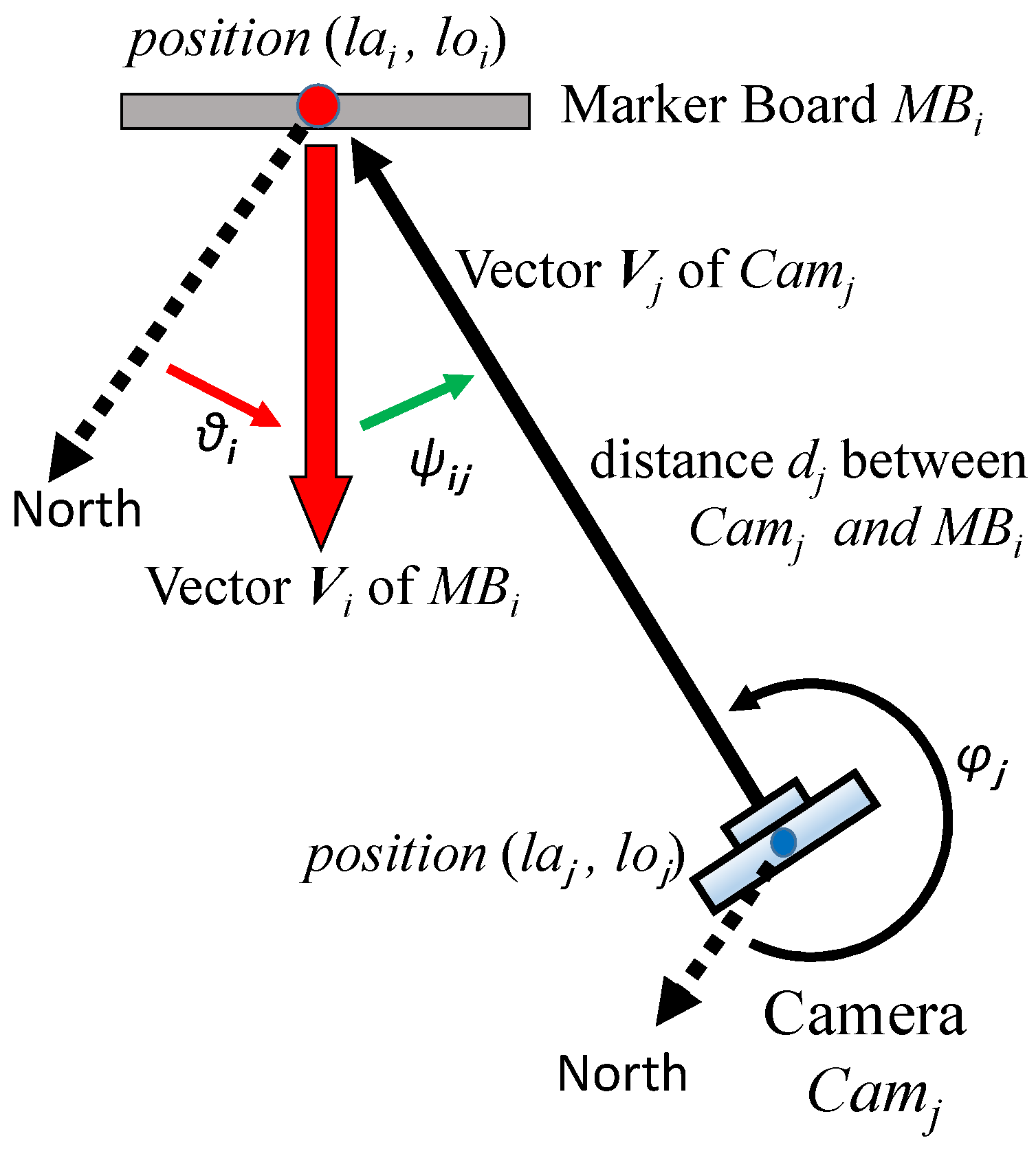
Although high-precision spatial tracking (on the order of centimeters) is necessary for indoor navigation with camera-based systems, the standard approach initializes the coordinate space based on the camera’s initial position and orientation at launch, with the z-axis aligned with the camera’s orientation. This local coordinate system differs from the global reference frame used to register objects within indoor space. To leverage these existing objects in navigation tasks, it becomes crucial to convert the camera’s position from the local frame to the global reference system. This subsection outlines the procedure for performing such a conversion.
Figure 3 illustrates converting the local coordinate values to a global coordinate system for indoor AR positioning by using a smartphone (
Figure 1, A5). The position (global coordinates) and direction (global direction, 0° points north) of the marker board
in the real world (e.g., the floor map signboard) are defined as
and
. The position (local coordinates) of the smartphone camera
is defined as
, and the distance and direction from
to
are defined as
and
, respectively. The relationship between these variables is defined by Equations (1) to (4).
is a function that converts the local 2D coordinate values in meters to global 2D coordinate values (longitude and latitude) and
is a function that rotates the 2D coordinate values around the origin by
.
4.3. Accumulated Error Correction with Periodical Calibration
One of the significant challenges in high-accuracy indoor positioning involves the accumulation of errors as the user moves. When these errors exceed acceptable limits, geofences may not activate as intended, leading to malfunctions in the navigation system. Therefore, it is necessary to conduct positioning calibration after the user has moved a predefined distance. The calibration can be easily accomplished by recognizing a location reference marker. Nonetheless, the following three elements are deemed crucial for practical applications.
Frequency of calibration: Empirical results from our experiments on positioning accuracy in spatial tracking with VIO (referenced in
Section 6.1) indicate that the user will experience an error of approximately 0.3 m after moving 30 m at a normal walking speed of 3.6 km/h. Considering a human’s shoulder width of approximately 0.6 m, a smartphone held at the center line of the body will have a horizontal distance of 0.3 m to the body’s edge. Under these circumstances, a geofence designed to cover the width of a corridor may fail to activate if the positioning error exceeds 0.3 m. Consequently, we recommend calibration every 30 m, as this error margin is the maximum tolerable threshold for a smartphone-based indoor navigation system.
Marker for calibration: The location reference markers should be strategically distributed throughout the building to cover the navigation service area adequately. Each marker should be placed within walking distance of less than 30 m from the nearest one. In the context of museums, we recommend utilizing signboards and exhibits (suppose they are stationary) as location reference markers. This approach allows the smartphone to naturally and cost-effectively calibrate accumulated positioning errors while the user is engaged in viewing the exhibits.
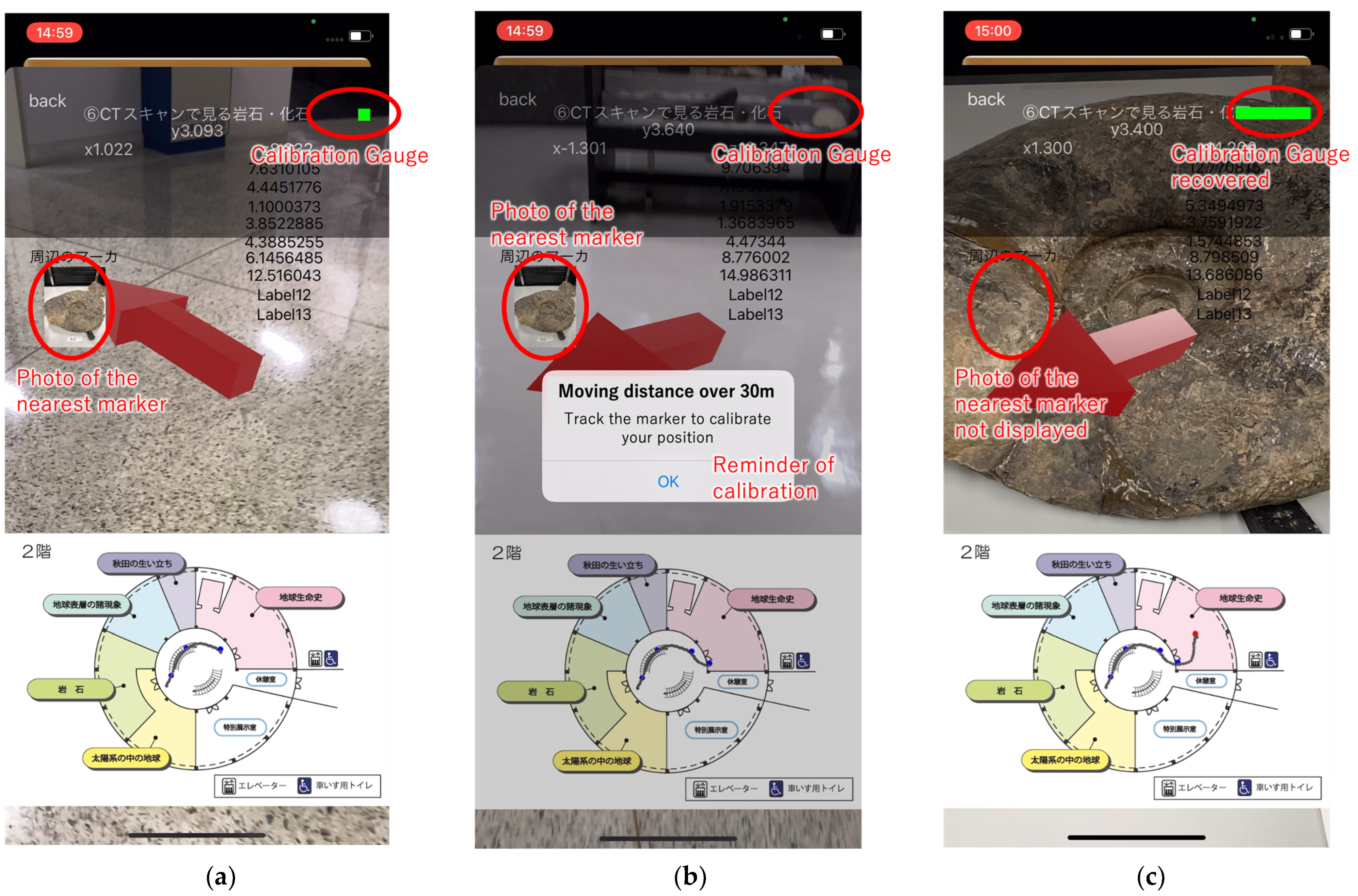
User interface guiding the calibration: The user interface (UI) must support two fundamental functions: firstly, notifying the user of the need for calibration, and secondly, guiding the user to the reference marker. In our experimental application, we incorporated a gauge bar that signals the necessity for calibration. When the walking distance exceeds 30 m, and the gauge is depleted, an alert is triggered to remind the user to locate a marker. Simultaneously, the photo of the nearest marker is displayed to assist in calibration.
Our experimental application implements the strategies based on the above three elements. Preliminary results from a demonstration experiment described in
Section 6.3 demonstrate the effectiveness of accumulative error calibration.
5. Design and Development of Indoor AR Navigation Services Based on Geofencing
5.1. Location-Based Service Design Based on Geofencing
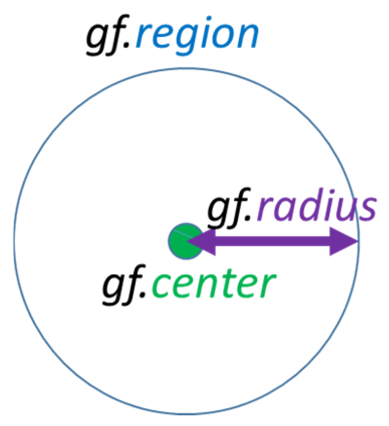
Our experimental indoor AR navigation application employs geofencing to provide AR-based direction instructions and audio guide services. While the shape of the geofence can be arbitrary, a circular boundary shape, as depicted in
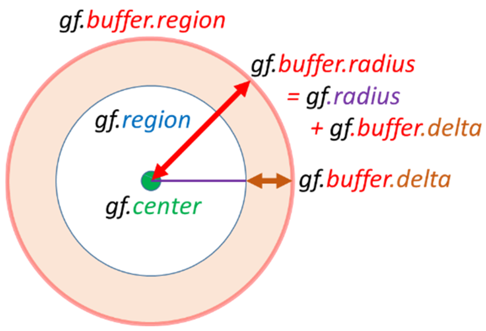
Figure 4, is most commonly used due to the simplicity of the calculation process. It is straightforward to determine whether the user has entered the boundary area by calculating the Euclidean distance to the center point. When the user’s location is determined using spatial tracking technologies such as GNSS, Bluetooth, or VIO, positioning errors are typical. A buffer method that expands the geofence’s boundary area to account for these errors proves to be an effective error absorption mechanism, as illustrated in
Figure 5. Considering the positioning oscillation, dynamically expanding the buffer area upon a user’s geofence check-ins can effectively reduce check-in and check-out errors, even in worst-case scenarios. Similarly, decreasing the buffer area dynamically after checking out can prevent oscillation misfunctions.
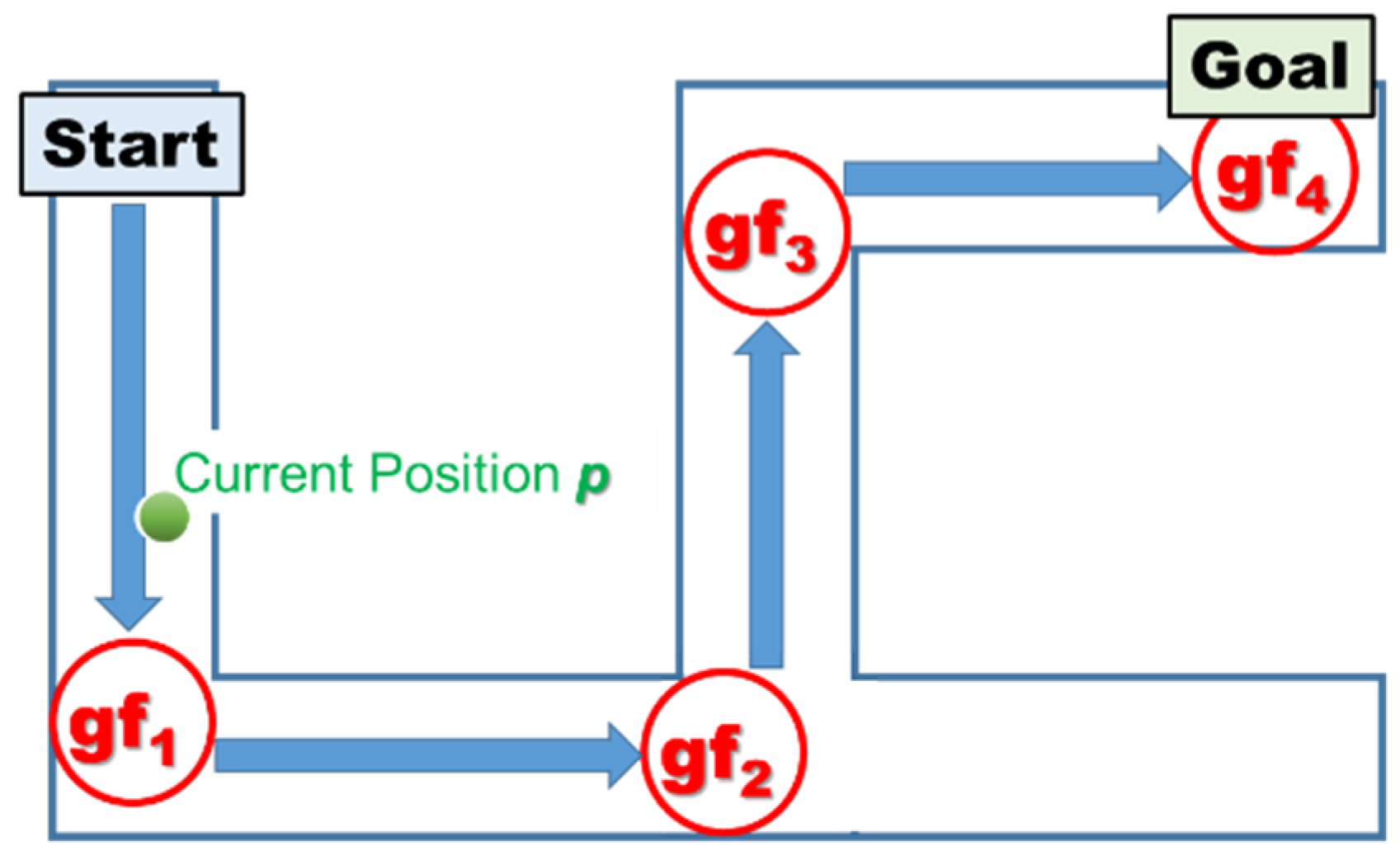
An example of a mobile service using geofencing is audio navigation. When guiding a user along a route to a destination, push-type services such as voice instructions with directions and distances are provided at waypoints such as junctions.
Figure 6 shows an example of route placement with geofencing (
Figure 1, C), demonstrating appropriate geofence locations and boundary area sizes. Start → gf
1 → gf
2 → gf
3 → gf
4 (Goal) is the route, and the geofence gf
i is used to represent the route. For example, voice narration can be pushed to the user when the user’s position (
p), which is acquired by VIO, enters the boundary area range of the geofence. Suppose that the boundary area of the geofence can be narrowed to the minimum necessary range. In this case, providing high-quality push-type services at more appropriate locations and timings becomes possible. However, a possible risk is that the geofence will not be able to capture the user’s location correctly when the accumulated positioning error becomes too large. On the other hand, increasing the geofence radius will reduce the failure of user tracking, but the push-type service may be misplaced or delivered too early, which will result in inadequate and degraded service quality. The trade-off between the service quality in terms of the appropriate location or push timing and the accuracy of the geofencing check-in and check-out is essential in setting the range of the geofence’s area.
In the case of visual navigation using AR, a 3D sign pointing to the next geofence (as a waypoint) from the user’s current position is overlaid on the real-world image from the camera (
Figure 1, B1), as illustrated in
Figure 2. When checking into the geofence (waypoint) (
Figure 1, B3), the next geofence is set as the next waypoint, and the 3D sign changes to point to the next direction. In this way, various LBS applications can be designed based on the concept of geofencing.
5.2. Indoor Geofence Space Design
This subsection discusses how to determine the location and size of a geofence. In an ideal scenario in which indoor positioning is error-free, the geofence should be centered at the optimal location for push services, such as the audio guides, and its radius should be set to ensure that the service remains consistently available as the user moves within the geofence. In practice, however, the placement and size of a geofence are influenced by several elements, including the spatial structure of the building, the intended function of the geofence, the user’s moving speed, the positioning sample rate, human dimensions, and the inherent positioning error.
Building space structure: In general, when placing a geofence at a corridor or entrance for a waypoint, its diameter should match the width of the corridor or entrance. When deploying a geofence for an exhibit, it should ideally be triggered as soon as the user sees it.
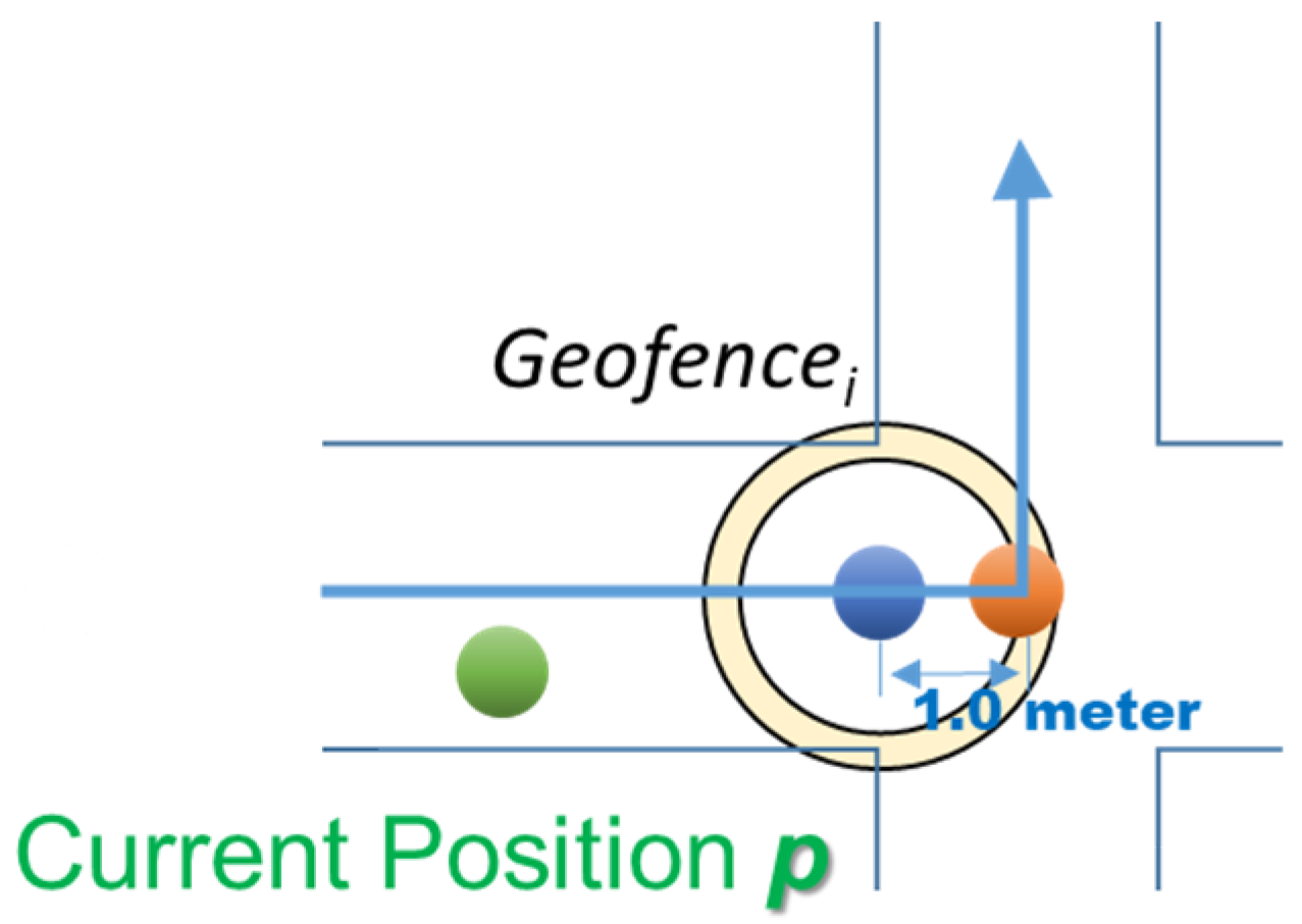
The geofence’s function: A geofence designed to trigger the introduction of an exhibit typically aligns its center with the exhibit’s location. Conversely, a geofence intended to provide direction updates at a waypoint should be positioned in advance of the location.
The user’s moving speed and sampling rate: The geofence should be designed to ensure that at least one sampled trajectory point falls within its range when the user passes by. For instance, when providing direction updates at a waypoint, such as a turn at a junction, and assuming notification is required one second before reaching the junction, the geofence’s center point should be placed approximately a one-second walking distance ahead of the junction (based on an average walking speed of roughly one meter per second), as illustrated in
Figure 7.
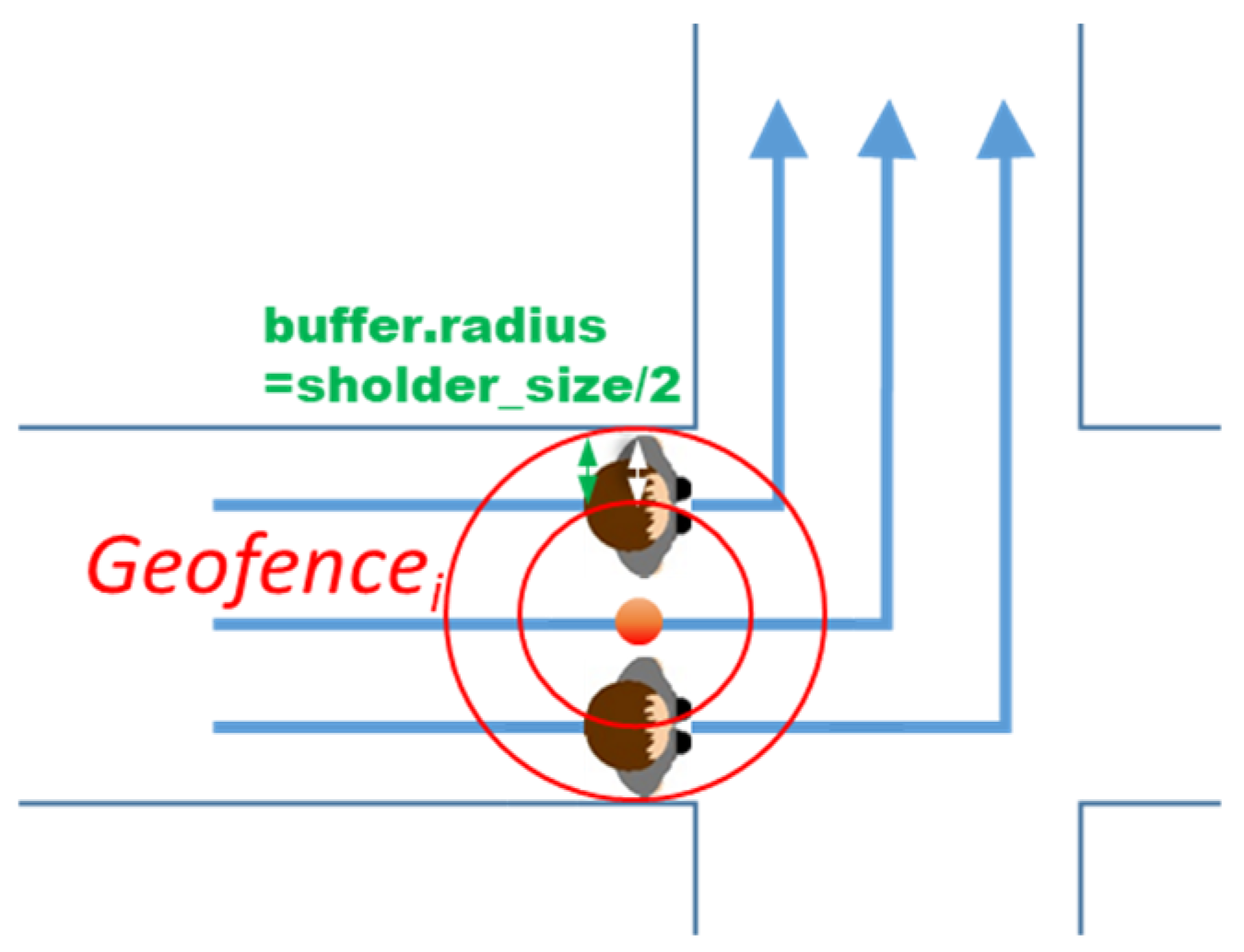
Human dimension: As VIO-based positioning can achieve centimeter-level accuracy, the dimensions of the human body cannot be overlooked when designing geofences. Considering a typical human shoulder width (including clothing) of 0.6 m, the radius of a geofence covering the width of a corridor could theoretically be reduced by 0.3 m (i.e., half the shoulder width), as shown in
Figure 8. This adjustment accounts for the smartphone being held at the center of the body, ensuring it remains within the geofence.
Positioning error: As mentioned in
Section 5.1, the radius of the geofence should be enlarged to accommodate the expected positioning error. If the periodical calibration described in
Section 4.3 is effective and the error is generally maintained below 0.3 m, the geofence radius may be increased by 0.3 m. This increment aligns with the reduction of 0.3 m, accounting for half the human shoulder width.
When developing the experimental application, the geofence size was determined empirically through extensive on-site experiments. Various settings were tested to assess whether entry into a geofence triggers the optional start of audio narration and simultaneously updates the virtual 3D arrow icon pointing toward the next waypoint. Although a smaller geofence radius might offer a more precise location and timing for push notifications, the impact of spatial tracking errors was also considered. Consequently, a decision was made to incorporate the five aforementioned elements to determine each geofence radius at a level that avoids user discomfort without compromising functionality.
5.3. Prototype Development and the Field for Experiments
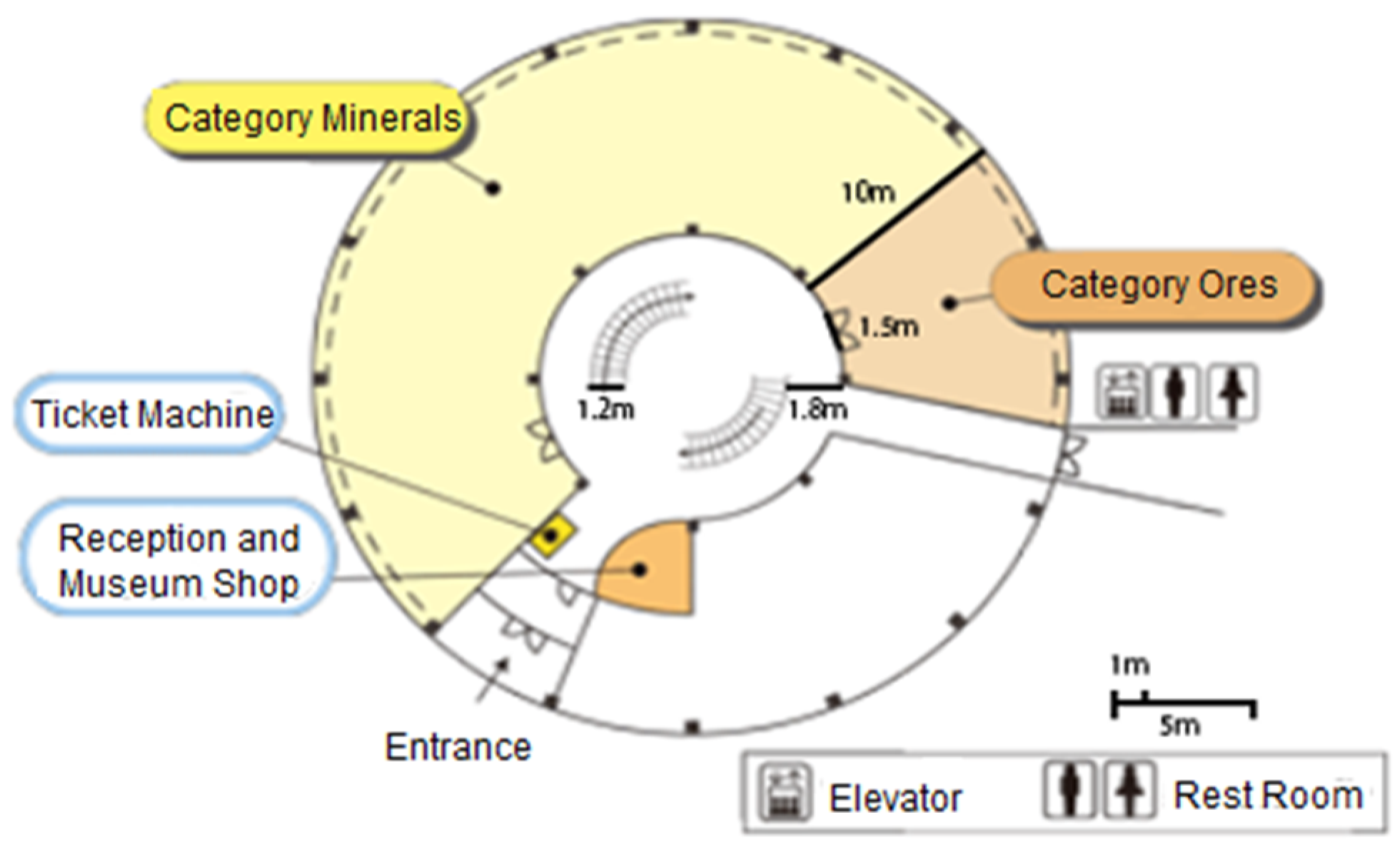
We implemented an experimental indoor AR navigation application using Apple Inc.’s ARKit and conducted a demonstration experiment at the Mineral Industry Museum, Akita University, by using its floor map, as shown in
Figure 9. The museum is a circular building with three floors, and the spiral staircase in the center of the building connects the different floors. The width of the spiral staircase is 1.2 m, and the width of the corridors is 1.8 m. The width of the entrance door to the exhibition hall (i.e., the doughnut) is 1.5 m. The doughnut area of the exhibition hall has an inner radius of 6 m and an outer radius of 16 m.
In the demonstration experiment, the floor map signboard on the first floor, which served as a location reference marker, was recognized by the smartphone’s camera to set the initial spatial coordinates for the smartphone’s position and direction (
Figure 1, A). The subsequent location estimations were performed as the user was moving by tracking the smartphone’s position and orientation using ARKit’s VIO function, which uses the iPhone 11’s motion sensor and camera.
6. Implementation Experiments
This section focuses on the experiments conducted to implement our proposed framework. First, we present the results of empirical experiments on the degree of cumulative error caused by spatial tracking with the camera. The final cumulative error is extremely important in the design of indoor AR navigation because it determines the radius and location settings of geofences and the calibration timing. Second, the prototype introduced in
Section 5.3 is tested in the actual application field to demonstrate the functionality of indoor AR navigation and the feasibility of the proposed framework. Third, we emphasized the realization of UI for periodical calibration and tested its effectiveness for accumulative error correction. All these experiments were conducted by the members of our research team.
6.1. Positioning Accuracy Evaluation in Spatial Tracking with VIO
In indoor AR navigation, the accuracy of positioning is expected to decrease with prolonged use of spatial tracking with VIO. This decrease in accuracy is significant for the design of such services. This subsection presents the results of an experiment designed to evaluate spatial accuracy and its rate of decline using the original indoor AR navigation application developed by us. The experiment involved measuring errors in spatial tracking with a camera within the real-world environment of a museum hallway. For this experiment, signs made of tape—approximately 2 cm in width—were placed on the floor at 1 m intervals to outline the intended route. The actual path was navigated using an AR app, and the discrepancy between the tape’s real-world location and its position as identified in the digital space by the AR app was measured with a ruler.
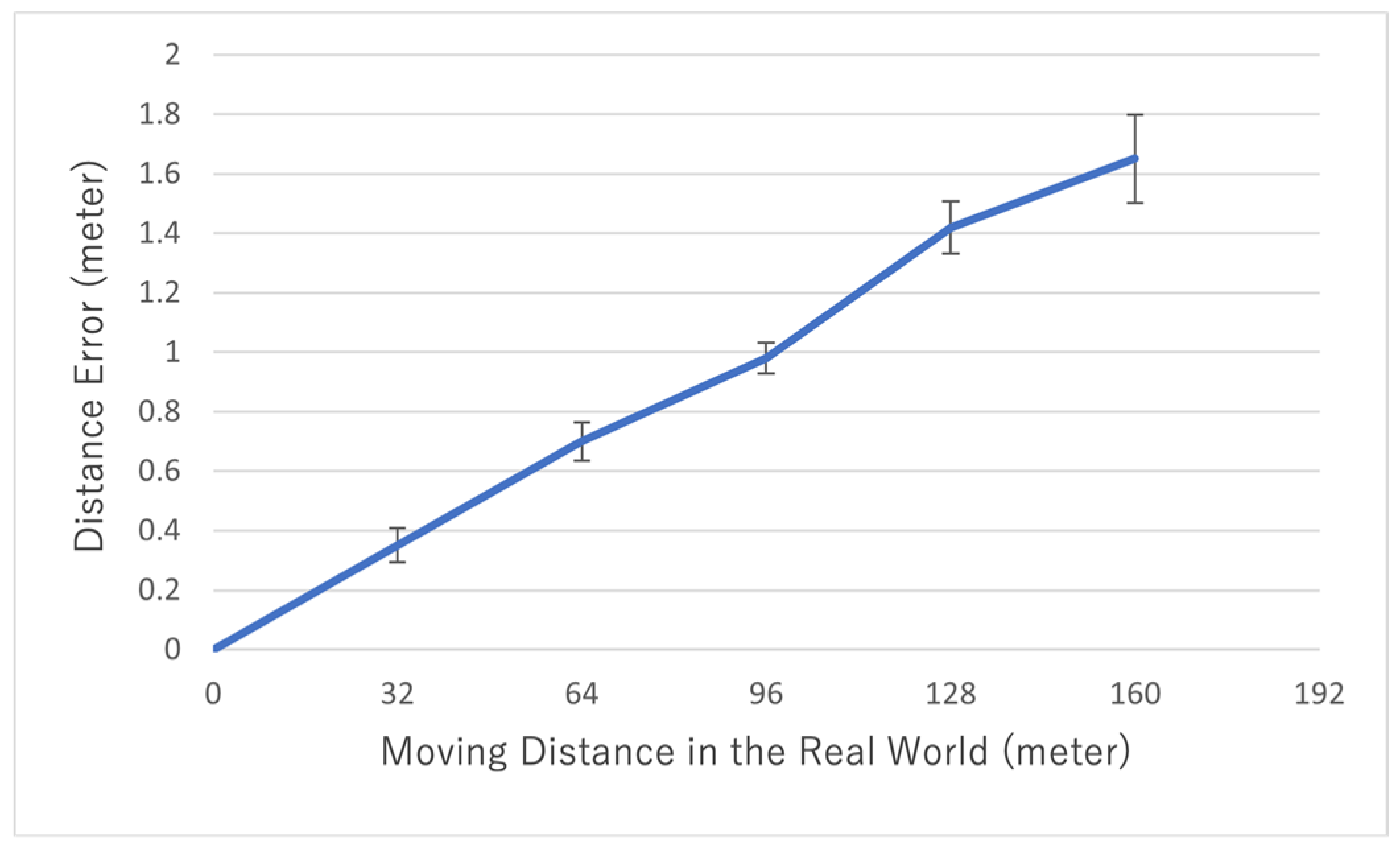
Figure 10 shows the results of the spatial accuracy evaluation of positioning using spatial tracking with VIO, with Apple Inc.’s iPhone 11 as the target device (with the functions of the ARWorldTrackingConfiguration class in Apple Inc.’s ARKit library). In this experiment, the user walked at a normal speed of approximately 1.0 m/sec while holding the smartphone almost vertically in their hand and pointing the camera in the direction that they were moving. As the distance they moved increased, the positioning error increased, resulting in an error of approximately 1.6 m when 160 m was covered. The convolutional error was about 1%, which indicated a linear increase in the positioning error. With this level of error, indoor AR positioning of sufficient quality is feasible. However, because the positioning error accumulates as the distance moved increases, periodic positioning calibration is required.
Figure 11a visualizes an example of the raw data obtained using spatial tracking with VIO (sample rate: 0.1 s). Smoothing is necessary because outliers sometimes occur.
Figure 11b shows an example of smoothing using the median value for the previous 1.0 s. Smoothing overcomes the problem of positioning error outliers and provides more appropriate and stable location information, thus avoiding straggling when providing LBS services. The drawback of smoothing is the delay in error detection; however, this is not a major problem in use cases involving walking.
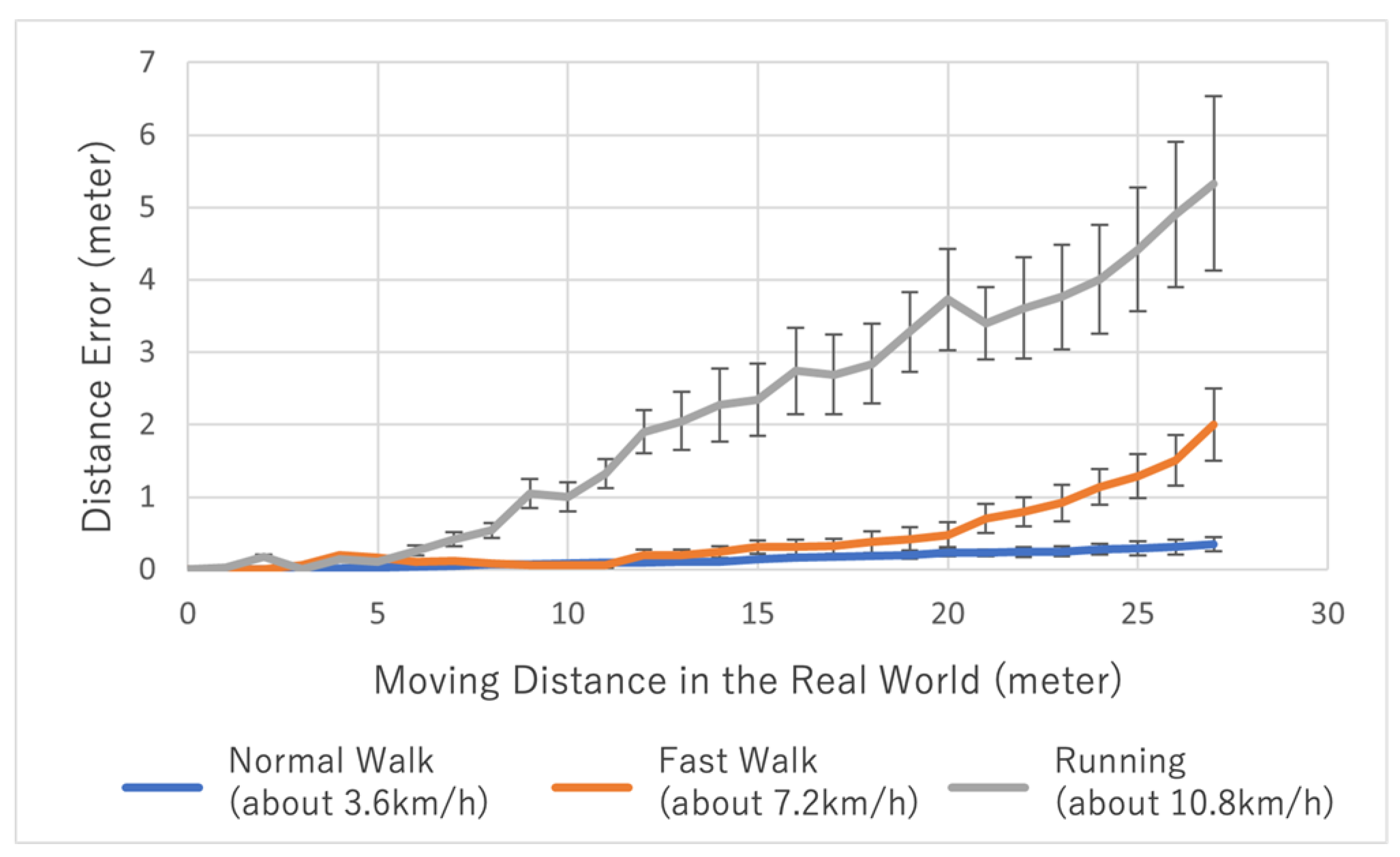
Figure 12 shows how much the error in spatial tracking by VIO varies depending on how the user moves with the smartphone. As can be seen, error accumulation varies depending on the user’s walking speed, the swaying of the smartphone, and even the model of the smartphone. Although the errors vary depending on how the user uses the smartphone, it is possible to estimate the movement error to some extent if we know the user’s preferences (walking style, smartphone model, etc.).
6.2. Demonstration Experiment of Basic Indoor AR Navigation Functions for the Museum
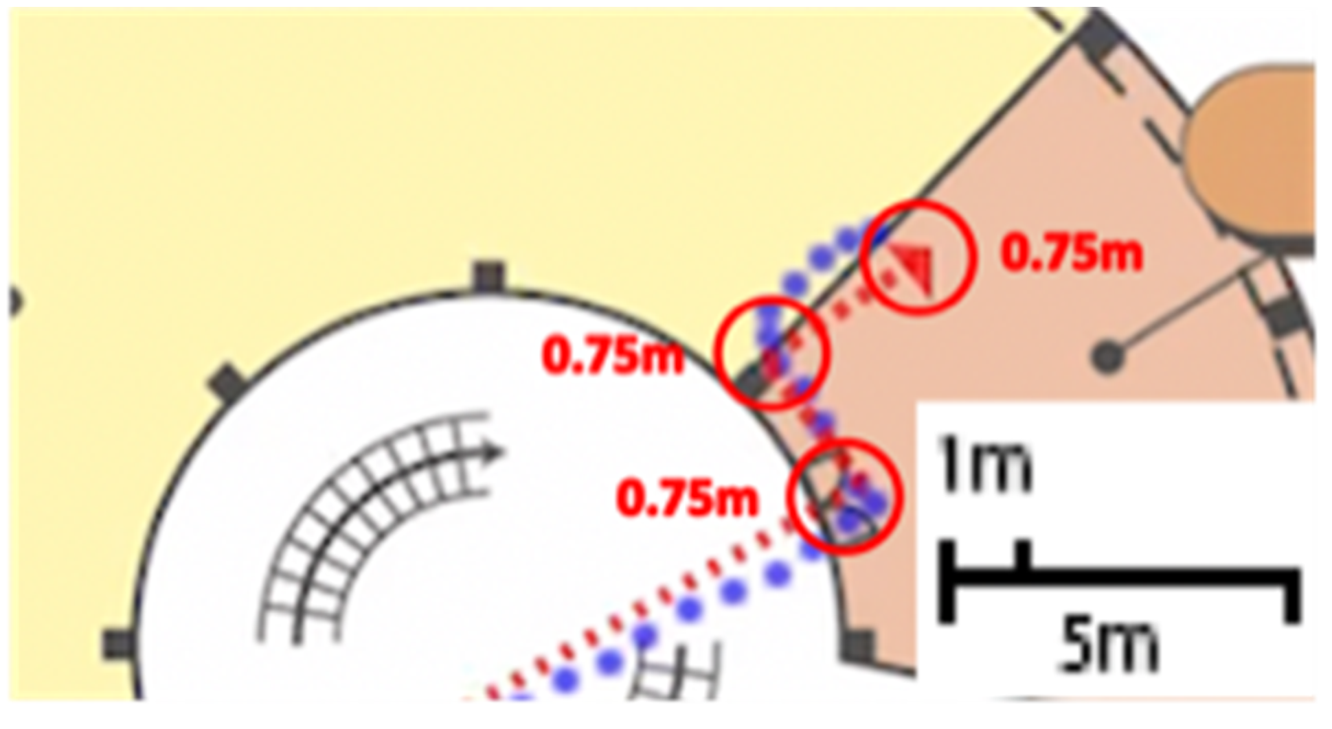
To test the navigation functionality of the framework, we set up several navigation service routes from the entrance to the target exhibits on the first floor of the Mineral Industry Museum and used the prototype to follow the routes to see if the current position is tracked accurately and the geofences are triggered correctly. For example, the route to a target exhibit (Rhodochrosite) is composed of three geofences as waypoints, each having a radius of 0.75 m to cover the width of the path, as illustrated in
Figure 13. The red dotted line represents the planned walking route, and the blue dots represent the actual movement trajectory data recorded with the prototype during the experiment. The navigation service is provided as necessary when the movement trajectory data falls within the geofence boundary area, which successfully triggers the direction updates.
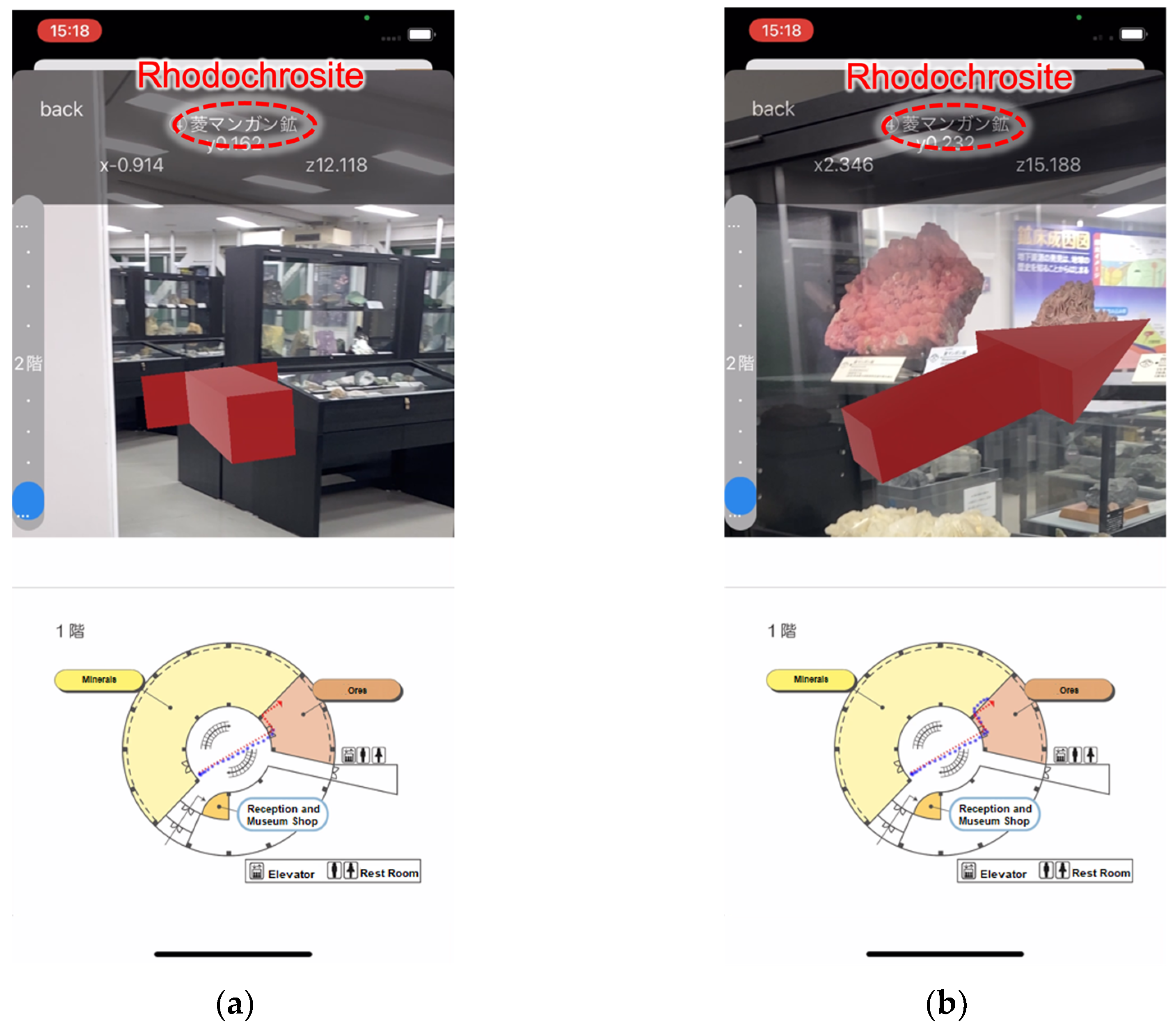
Figure 14a illustrates that upon the user’s entry into the exhibition area from the corridor—crossing the boundary of the geofence located at the exhibition’s entrance—a check-in event is immediately triggered. The virtual 3D arrow, which guides the user’s movement, then changes direction, signaling through the AR screen that the user should turn left. Simultaneously, a voice narration instructs the user to make a left turn.
As depicted in
Figure 14b, as the user approaches the target exhibit, the 3D sign immediately points toward it upon geofence check-in, and a voice narration introduces the exhibit. This demonstrates that a framework leveraging spatial design and high-accuracy indoor positioning can effectively realize a practical indoor AR navigation system.
The virtual 3D arrow is 2 m long and is positioned 5 m away from the smartphone camera. It is designed to occupy approximately 60% of the screen’s width. The smartphone’s field of view is 60°, divided equally with 30° to both the left and right. The rationale behind the 5 m placement is founded on a design principle that provides audio guidance roughly 5 sec in advance, followed by a succinct narration (e.g., “Please turn right”) lasting for about 2 sec and, thus, allowing the user 3 sec to react. The user is assumed to walk at a speed of 1 m/s.
6.3. Demonstration Experiment of Accumulated Error Correction
To indicate the necessity of position calibration, we add a gauge bar in the main UI of the prototype that decreases according to the increase in the user’s moving distance, as shown in
Figure 15a. When the walking distance goes over 30 m, and the gauge becomes empty, an alert, as shown in
Figure 15b, will be popped to remind the user to find a marker to calibrate the position. At the same time, a photo of the nearest reference marker is displayed. As shown in
Figure 15c, the gauge bar becomes full again after calibration.
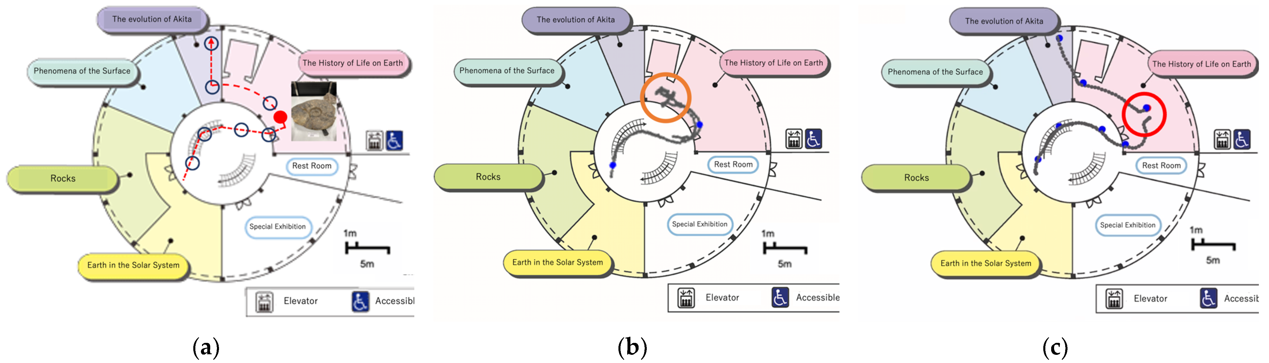
In a preliminary experiment, the user successfully navigated to an exhibit within a walking distance of 20 m without positioning error correction. However, when navigated to an exhibit with a 40 m walking distance, as shown in
Figure 16a, the user could not find the way to the target because the accumulated positioning error became unignorable that the waypoint geofence could not be correctly triggered, as shown in the orange circle in
Figure 16b. If the user calibrated the position in the middle of the route with the marker indicated as a red dot in
Figure 16a, they could successfully find the exhibit. The red circle in
Figure 16c shows that the trajectory jumped because of calibration.
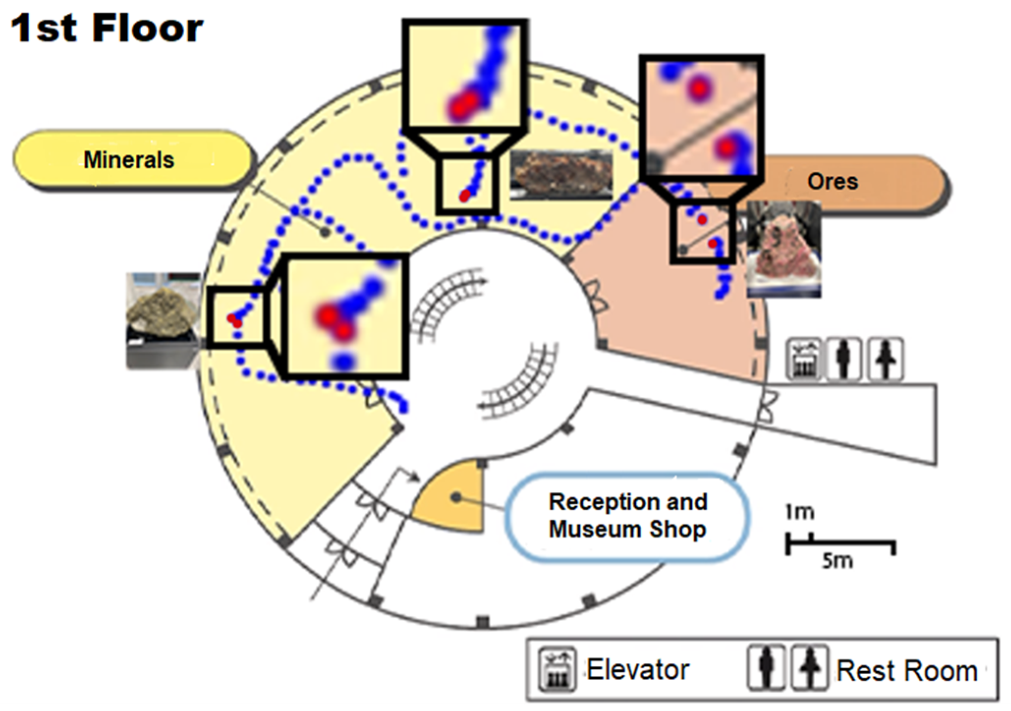
We suggest that utilizing exhibits as calibration makers instead of additional images or signboards can be a low-cost method as the calibration can be conducted naturally and unconsciously while the user is viewing the exhibits.
Figure 17 demonstrates an example of this proposed method, in which the user’s current position is calibrated three times along the navigation route when the smartphone’s camera is pointed toward the exhibits. The corrected positions are visualized as the red dots on the map.
7. Discussion
7.1. Devices
The proposed framework has chosen smartphones as the target devices due to their ubiquity and the mature AR development frameworks included in the major operating systems. The prototype was implemented with Apple Inc.’s ARKit framework on iOS. Thus, it can be operated on a wide range of iPhones and iPads. Google LLC also provides Android and iOS developers with ARCore [
39], which has similar functionality. Therefore, the framework can be implemented in Android smartphones and tablets in a manner similar to the demonstrated prototype.
One disadvantage of image-tracking-based AR navigation is that users need to keep the camera in a certain range of angles and distances to achieve successful recognition of the reference markers. Users unfamiliar with AR applications may find it challenging to consistently maintain this requirement. In addition, when implemented with smartphones, after recognizing the reference marker, users need to keep holding the device so the camera has enough view to track positions and align displays. This can be tiresome and detrimental to the device’s battery life. Meanwhile, holding a smartphone while walking is typically considered unsafe, even if the user can perceive the front view from the screen. Further studies should explore solutions incorporating other indoor positioning technologies, enabling users to put down their devices while moving without losing track of the position.
Although still expensive and not widely available at present, wearable devices such as head-mount displays (HMDs) will be an important vehicle for AR applications in the future. It is posited that the proposed framework can be modified to accommodate HMDs as long as the device supports VIO because the underlying principles remain unchanged.
7.2. Software Implementation
The prototype was implemented using major AR frameworks provided by a smartphone OS, that is, Apple Inc.’s iOS. The primary advantage of utilizing these mature AR frameworks lies in their ease of development. Notably, they ensure cross-device consistency in image tracking and positioning despite variations in camera and sensor parameters. This approach does constrain developers’ autonomy in certain respects. For instance, if a framework ceases to support a particular type of device following an update, the application will consequently lose compatibility with those devices.
The software, based on the proposed framework, is considered scalable due to its infrastructure-free and standalone features. The calibration solution developed to resolve the accumulative error problem enables its application for long navigation routes in large indoor areas. Once developed, the software can be adapted to different facilities by replacing the data (e.g., floor plans, markers, targets, and geofences) and content (e.g., audio guides, descriptions, and photos).
7.3. Indoor Geofencing Design
The significance of geofencing design in indoor AR navigation systems is often underestimated. Although geofencing is a well-established technique in LBS and may seem straightforward, its effective implementation is crucial for enhancing user experiences. Properly designed geofencing, in conjunction with accurate tracking, can significantly enhance the user experience by providing timely and location-specific information or navigation cues, especially in complex indoor environments such as museums or shopping malls. Implementing geofencing indoors presents unique challenges not encountered in outdoor settings or beacon-based solutions. The precision required is considerably higher due to the complexity of the indoor spaces and the need for centimeter-level alignments in AR views. Consequently, elements including human dimensions, building structures, positioning errors, walking speed, and methods of displaying navigation cues must be considered.
Our current geofencing design is derived from empirical experiments, and its applicability to different indoor settings remains unclear. For instance, if improved indoor positioning accuracy can be achieved, then the buffer adjustment for the geofence radius needs to be modified accordingly. The principle of indoor geofencing design and the systematic determination of the placement and size of geofences remain important areas for future research. It is also necessary to incorporate user feedback into the design of indoor geofencing.
7.4. Limitations
Our framework has been tested with a single prototype in only one indoor environment. While this provided initial insights into the conceptual framework and validation of the key technologies, the results may not generalize across different types of indoor settings, such as shopping malls, university buildings, and hospitals, where space structures and user behaviors can vary.
The current stage of our research did not include extensive usability tests with actual users, which limited our understanding of the effectiveness of the proposed geofencing design and calibration strategy and overall user satisfaction. The prototype was not subjected to public experimentation, which would provide a more robust validation of the system’s effectiveness, reliability, and acceptance in the real world by different user groups, especially those who are not familiar with AR technologies.
This study has not focused extensively on the methodologies for data acquisition and organization, which are critical for scaling the application to other venues and for further development. The registration of reference location markers, placement and tuning of geofences, and association of media content to the navigation targets can be labor-intensive. Effective data acquisition and efficient data organization can facilitate the system’s scalability and maintenance.
8. Conclusions
The present paper has presented a novel framework for indoor AR navigation that overcomes two key challenges: operating within wide, absolute coordinate spaces and minimizing cumulative positioning errors in camera-based spatial tracking. This framework utilizes high-accuracy spatial tracking enabled by the VIO of contemporary smartphones, which is enhanced by the integration of location reference image markers and a local-to-global spatial coordinate transformation, hence ensuring precise positioning within a global coordinate context. A strategy of periodic image-based calibration has been introduced, with designed user interactions guiding the calibration markers, significantly reducing the impact of accumulated errors and improving navigation accuracy over extended distances. This approach was implemented in an indoor AR navigation system deployed at the Mineral Industry Museum of Akita University, where demonstration experiments validated its effectiveness.
Our work stands apart from the current academic literature as a pioneering systematic framework for indoor AR navigation design. The key strengths include the ability to extend high-accuracy local positioning to larger areas, the innovative calibration method to minimize accumulated errors, and its practical application in an existing indoor setting. Although reliance on VIO and periodic calibration could be considered limitations, they offer opportunities for further research in usability and accuracy enhancements.
Future research will focus on usability experiments and user studies using an improved prototype with a more sophisticated user interface. We aim to refine our framework by exploring different geofence settings for practical spatial design and investigating solutions to improve indoor LBS usability and functionality. By comparing various settings and exploring new technologies, we can extract principles that will guide the development of practical and high-quality AR navigation applications and services, further contributing to the field of indoor AR navigation.
Author Contributions
Conceptualization, M.L., M.A., K.O., T.U. and R.S.; data curation, M.L., K.O., K.I. and Y.J.; formal analysis, M.L., M.A. and K.O.; funding acquisition, M.A. and M.L.; investigation, M.L., M.A., K.O., K.I. and Y.J.; methodology, M.L., M.A. and K.O.; project administration, M.L., M.A., T.U. and R.S.; resources, M.L., M.A. and T.U.; software, M.L., M.A., K.O., K.I. and Y.J.; supervision, M.L. and M.A.; validation, M.L. and M.A.; visualization, M.L., K.O., K.I. and Y.J.; writing—original draft, M.L.; writing—review and editing, M.L., M.A., T.U. and R.S. All authors have read and agreed to the published version of the manuscript.
Funding
This research was funded by JSPS Grant-in-Aid, grant numbers JP23K11362, JP24K15631, JP22H00764, and JP19H04120.
Institutional Review Board Statement
Not applicable.
Informed Consent Statement
Not applicable.
Data Availability Statement
The data presented in this study are available on request from the corresponding author. The data related to the Mining Museum’s property, including the floor plans and photos of the signboards and exhibits, will not be available without the museum’s permission.
Acknowledgments
We deeply appreciate Shinpei Ito and Akinori Takahashi for their great contributions to our research on constructing a framework for indoor AR navigation. We further thank the Mineral Industry Museum, Akita University, for providing the field for the service experiments.
Conflicts of Interest
Kohei Oba is employed by the Shimizu Corporation. The authors declare no conflicts of interest.
References
- Valentin, J.; Kowdle, A.; Barron, J.T.; Wadhwa, N.; Dzitsiuk, M.; Schoenberg, M.J.; Verma, V.; Csaszar, A.; Turner, E.L.; Dryanovski, I.; et al. Depth from motion for smartphone AR. ACM Trans. Graph. 2018, 37, 1–19. [Google Scholar] [CrossRef]
- Wang, J.; Wang, Q.; Saeed, U. A visual-GPS fusion based outdoor augmented reality method. In Proceedings of the 16th ACM SIGGRAPH International Conference on Virtual-Reality Continuum and Its Applications in Industry, Tokyo, Japan, 2–3 December 2018; Article No. 25. pp. 1–4. [Google Scholar] [CrossRef]
- Kan, T.W.; Teng, C.H.; Chen, M.Y. QR code based augmented reality applications. In Handbook of Augmented Reality; Furht, B., Ed.; Springer: New York, NY, USA, 2011; pp. 339–354. [Google Scholar] [CrossRef]
- Guan, F.; Fang, Z.; Wang, L.; Zhang, X.; Zhong, H.; Huang, H. Modelling people’s perceived scene complexity of real-world environments using street-view panoramas and open geodata. ISPRS J. Photogram. Remote Sens. 2022, 186, 315–331. [Google Scholar] [CrossRef]
- Guastella, D.C.; Muscato, G. Learning-based methods of perception and navigation for ground vehicles in unstructured environments: A review. Sensors 2021, 21, 73. [Google Scholar] [CrossRef] [PubMed]
- Huang, H.; Gartner, G.; Krisp, J.M.; Raubal, M.; Van de Weghe, N. Location based services: Ongoing evolution and re-search agenda. J. Locat. Based Serv. 2018, 12, 63–93. [Google Scholar] [CrossRef]
- GPS Accuracy, National Coordination Office for Space-Based Positioning, Navigation, and Timing, USA. Available online: https://www.gps.gov/systems/gps/performance/accuracy/ (accessed on 8 March 2024).
- Zafari, F.; Gkelias, A.; Leung, K.K. A survey of indoor localization systems and technologies. IEEE Commun. Surv. Tutor. 2019, 21, 2568–2599. [Google Scholar] [CrossRef]
- Yang, T.; Cabani, A.; Chafouk, H. A survey of recent indoor localization scenarios and methodologies. Sensors 2021, 21, 8086. [Google Scholar] [CrossRef] [PubMed]
- Mendoza-Silva, G.M.; Torres-Sospedra, J.; Huerta, J. A meta-review of indoor positioning systems. Sensors 2019, 19, 4507. [Google Scholar] [CrossRef] [PubMed]
- Kang, T.; Shin, Y. Indoor navigation algorithm based on a smartphone inertial measurement unit and map matching. In Proceedings of the 12th International Conference on ICT Convergence, Jeju Island, Republic of Korea, 20–22 October 2021; pp. 1421–1424. [Google Scholar] [CrossRef]
- Pan, M.S.; Li, K.Y. ezNavi: An easy-to-operate indoor navigation system based on pedestrian dead reckoning and crowdsourced user trajectories. IEEE Trans. Mob. Comput. 2019, 20, 488–501. [Google Scholar] [CrossRef]
- Martinelli, A. Vision and IMU data fusion: Closed-form solutions for attitude, speed, absolute scale, and bias determination. IEEE Trans. Robot. 2012, 28, 44–60. [Google Scholar] [CrossRef]
- Lupton, T.; Sukkarieh, S. Visual–inertial-aided navigation for high-dynamic motion in built environments without initial conditions. IEEE Trans. Robot. 2012, 28, 61–76. [Google Scholar] [CrossRef]
- Understanding World Tracking: Discover Features and Best Practices for Building Rear-Camera AR Experiences. Available online: https://developer.apple.com/documentation/arkit/arkit_in_ios/configuration_objects/understanding_world_tracking (accessed on 8 March 2024).
- Garzon, S.R.; Deva, B. Geofencing 2.0: Taking Location-Based Notifications to the Next Level. In Proceedings of the 2014 ACM International Joint Conference on Pervasive and Ubiquitous Computing, Seattle, WA, USA, 13–17 September 2014; pp. 921–932. [Google Scholar] [CrossRef]
- Mineral Industry Museum, Akita University. Available online: https://www.mus.akita-u.ac.jp/indexE.html (accessed on 8 March 2024).
- Cheliotis, K.; Liarokapis, F.; Kokla, M.; Tomai, E.; Pastra, K.; Anastopoulou, N.; Bezerianou, M.; Darra, A.; Kavouras, M. A systematic review of application development in augmented reality navigation research. Cartogr. Geogr. Inf. Sci. 2023, 50, 249–271. [Google Scholar] [CrossRef]
- Liu, B.; Ding, L.; Meng, L. Spatial knowledge acquisition with virtual semantic landmarks in mixed reality-based indoor navigation. Cartogr. Geogr. Inf. Sci. 2021, 48, 305–319. [Google Scholar] [CrossRef]
- Liu, B.; Ding, L.; Wang, S.; Meng, L. Designing Mixed Reality-Based Indoor Navigation for User Studies. KN J. Cartogr. Geogr. Inf. 2022, 72, 129–138. [Google Scholar] [CrossRef]
- Huang, B.-C.; Hsu, J.; Chu, E.T.-H.; Wu, H.-M. ARBIN: Augmented reality based indoor navigation system. Sensors 2020, 20, 5890. [Google Scholar] [CrossRef] [PubMed]
- Chehreghan, A.; Saadatzadeh, E.; Abbaspour, R. Infrastructure-free indoor navigation based on smartphone sensors in smart buildings. J. Locat. Based Serv. 2023, 17, 145–184. [Google Scholar] [CrossRef]
- Mulloni, A.; Wagner, D.; Barakonyi, I.; Schmalstieg, D. Indoor positioning and navigation with camera phones. IEEE Pervasive Comput. 2009, 8, 22–31. [Google Scholar] [CrossRef]
- Khan, D.; Cheng, Z.; Uchiyama, H.; Ali, S.; Asshad, M.; Kiyokawa, K. Recent advances in vision-based indoor navigation: A systematic literature review. Comput. Graph. 2022, 104, 24–45. [Google Scholar] [CrossRef]
- Chekhlov, D.; Gee, A.P.; Calway, A.; Mayol-Cuevas, W. Ninja on a plane: Automatic discovery of physical planes for augmented reality using visual SLAM. In Proceedings of the 6th IEEE and ACM International Symposium on Mixed and Augmented Reality, Nara, Japan, 13–17 November 2007; pp. 153–156. [Google Scholar] [CrossRef]
- Komianos, V. Immersive applications in museums: An analysis of the use of XR technologies and the provided functionality based on systematic literature review. JOIV Int. J. Inform. Vis. 2022, 6, 60–73. [Google Scholar] [CrossRef]
- Shewail, A.S.; Elsayed, N.A.; Zayed, H.H. Survey of indoor tracking systems using augmented reality. IAES Int. J. Artif. Intell. 2023, 12, 402–414. [Google Scholar] [CrossRef]
- Rubio-Sandoval, J.I.; Martinez-Rodriguez, J.L.; Lopez-Arevalo, I.; Rios-Alvarado, A.B.; Rodriguez-Rodriguez, A.J.; Vargas-Requena, D.T. An Indoor Navigation Methodology for Mobile Devices by Integrating Augmented Reality and Semantic Web. Sensors 2021, 21, 5435. [Google Scholar] [CrossRef]
- Fajrianti, E.D.; Funabiki, N.; Sukaridhoto, S.; Panduman, Y.Y.F.; Dezheng, K.; Shihao, F.; Surya Pradhana, A.A. INSUS: Indoor Navigation System Using Unity and Smartphone for User Ambulation Assistance. Information 2023, 14, 359. [Google Scholar] [CrossRef]
- Shevchenko, Y.; Reips, U.-D. Geofencing in location-based behavioral research: Methodology, challenges, and implementation. Behav. Res. Methods 2023. [Google Scholar] [CrossRef]
- Lin, M.Y.C.; Nguyen, T.T.; Cheng, E.Y.L.; Le, A.N.H.; Cheng, J.M.S. Proximity marketing and Bluetooth beacon technology: A dynamic mechanism leading to relationship program receptiveness. J. Bus. Res. 2022, 141, 151–162. [Google Scholar] [CrossRef]
- Ullah, F.; Haq, H.U.; Khan, J.; Safeer, A.A.; Asif, U.; Lee, S. Wearable IoTs and Geo-Fencing Based Framework for COVID-19 Remote Patient Health Monitoring and Quarantine Management to Control the Pandemic. Electronics 2021, 10, 2035. [Google Scholar] [CrossRef]
- Ivanov, R. ExhibitXplorer: Enabling Personalized Content Delivery in Museums Using Contextual Geofencing and Artificial Intelligence. ISPRS Int. J. Geo-Inf. 2023, 12, 434. [Google Scholar] [CrossRef]
- Class ARWorldTrackingConfiguration: A Configuration That Tracks the Position of a Device in Relation to Objects in the Environment, Apple Inc. Available online: https://developer.apple.com/documentation/arkit/arworldtrackingconfiguration (accessed on 26 March 2024).
- Framework ARKit: Integrate Hardware Sensing Features to Produce Augmented Reality Apps and Games, Apple Inc. Available online: https://developer.apple.com/documentation/arkit (accessed on 8 March 2024).
- Qiu, X.; Yang, Z.; Yang, J.; Wang, Q.; Wang, D. Impact of AR Navigation Display Methods on Wayfinding Performance and Spatial Knowledge Acquisition. Int. J. Hum.-Comput. Interact. 2023, 40, 2676–2696. [Google Scholar] [CrossRef]
- Framework Core Motion: Process Accelerometer, Gyroscope, Pedometer, and Environment-Related Events, Apple Inc. Available online: https://developer.apple.com/documentation/coremotion (accessed on 8 March 2024).
- Platonov, J.; Heibel, H.; Meier, P. A mobile markerless AR system for maintenance and repair. In Proceedings of the 5th IEEE and ACM International Symposium on Mixed and Augmented Reality, Santa Barbara, CA, USA, 22–25 October 2006; pp. 105–108. [Google Scholar] [CrossRef]
- Overview of ARCore and Supported Development Environments-Google for Developers, Google LCC. Available online: https://developers.google.com/ar/develop (accessed on 10 May 2024).
Figure 1.
Data flow diagram of a simple framework for realizing indoor AR navigation.
Figure 1.
Data flow diagram of a simple framework for realizing indoor AR navigation.
Figure 2.
Example of indoor AR navigation prototype user interfaces as an iOS application.
Figure 2.
Example of indoor AR navigation prototype user interfaces as an iOS application.
Figure 3.
Transformation of local coordinates into a global coordinate system for indoor AR positioning.
Figure 3.
Transformation of local coordinates into a global coordinate system for indoor AR positioning.
Figure 4.
An example of a geofence with a circular boundary.
Figure 4.
An example of a geofence with a circular boundary.
Figure 5.
An example of a geofence with a buffering region.
Figure 5.
An example of a geofence with a buffering region.
Figure 6.
An example of a navigation route defined by geofences with appropriate positions and sizes.
Figure 6.
An example of a navigation route defined by geofences with appropriate positions and sizes.
Figure 7.
The center of a geofence is set at 1.0 m ahead of a junction point when the walking speed is 1.0 m/sec for the guidance narration to be provided 1.0 sec in advance.
Figure 7.
The center of a geofence is set at 1.0 m ahead of a junction point when the walking speed is 1.0 m/sec for the guidance narration to be provided 1.0 sec in advance.
Figure 8.
Indoor positioning error relative to the size of a human and the geofence’s diameter.
Figure 8.
Indoor positioning error relative to the size of a human and the geofence’s diameter.
Figure 9.
Floor map of the Mineral Industry Museum (1F), Akita University.
Figure 9.
Floor map of the Mineral Industry Museum (1F), Akita University.
Figure 10.
Example of the positioning accuracy evaluation of VIO-based spatial tracking.
Figure 10.
Example of the positioning accuracy evaluation of VIO-based spatial tracking.
Figure 11.
Characteristics of the raw data (0.1-s sampling) of VIO-based positioning and an improvement using a median filter: (a) Raw data (sampling rate: 0.1 s); (b) Data smoothed using the median from a set of data generated in the previous 1.0 s.
Figure 11.
Characteristics of the raw data (0.1-s sampling) of VIO-based positioning and an improvement using a median filter: (a) Raw data (sampling rate: 0.1 s); (b) Data smoothed using the median from a set of data generated in the previous 1.0 s.
Figure 12.
VIO-based positioning accuracy evaluation by moving modes.
Figure 12.
VIO-based positioning accuracy evaluation by moving modes.
Figure 13.
Examples of geofences for indoor AR navigation at the Mineral Industry Museum (1F), Akita University. The number (0.75 m) beside each geofence shows its radius. The red dotted line indicates the route to the user’s destination, and the blue dotted line represents the user’s trajectory.
Figure 13.
Examples of geofences for indoor AR navigation at the Mineral Industry Museum (1F), Akita University. The number (0.75 m) beside each geofence shows its radius. The red dotted line indicates the route to the user’s destination, and the blue dotted line represents the user’s trajectory.
Figure 14.
Examples of indoor AR navigation services for the Mineral Industry Museum (1F), Akita University: (a) transition from a corridor to an exhibition space; (b) arriving at the destination exhibition object.
Figure 14.
Examples of indoor AR navigation services for the Mineral Industry Museum (1F), Akita University: (a) transition from a corridor to an exhibition space; (b) arriving at the destination exhibition object.
Figure 15.
Examples of indoor AR navigation services for the Mineral Industry Museum, Akita University (2F), with positioning error correction implemented: (a) Calibration gauge decreases as walking distance increases; (b) Reminder of calibration, which occurs with the nearest marker displayed when the moving distance is over 30 m; (c) Calibration gauge recovers after calibration.
Figure 16.
The user’s moving trajectories when navigated with/without accumulated positioning error correction: (a) The route of navigation and the position of the marker for calibration (red dot); (b) The user lost direction (at the place in the orange circle) without positioning calibration; (c) The user reached the target with positioning calibration (conducted at the red circle).
Figure 17.
Examples of positioning error correction of exhibition objects via image-tracking using a smartphone’s camera. The blue dotted lines represent the user’s movement trajectory. The segments where the blue dotted lines are interrupted indicate areas where accumulated errors have been corrected. The corrected points are emphasized as red dots.
Table 1.
Performance evaluation of smartphone position and angle measurement using the smartphone’s camera.
Table 1.
Performance evaluation of smartphone position and angle measurement using the smartphone’s camera.
| | 0° (Front) | 15° | 30° | 45° | 60° |
|---|
| 15 cm | × | × | × | × | × |
| 30 cm | ○ | ○ | ○ | ○ | × |
| 45 cm | ○ | ○ | ○ | ○ | × |
| 60 cm | ○ | ○ | ○ | △ | × |
| 75 cm | ○ | ○ | △ | × | × |
| 90 cm | △ | △ | △ | × | × |
| 105 cm | △ | △ | × | × | × |
| 120 cm | × | × | × | × | × |
| Disclaimer/Publisher’s Note: The statements, opinions and data contained in all publications are solely those of the individual author(s) and contributor(s) and not of MDPI and/or the editor(s). MDPI and/or the editor(s) disclaim responsibility for any injury to people or property resulting from any ideas, methods, instructions or products referred to in the content. |
© 2024 by the authors. Licensee MDPI, Basel, Switzerland. This article is an open access article distributed under the terms and conditions of the Creative Commons Attribution (CC BY) license (https://creativecommons.org/licenses/by/4.0/).

 ,
, 


