Article

Hydrostructural Phenomena in a Wastewater Screening Channel with an Ascendable Sub-Screen Using the Arbitrary Lagrangian–Eulerian Approach

1
School of Mechanical Engineering, Kyungpook National University, 80 Daehakro, Buk-gu, Daegu 41566, Republic of Korea
2
I-ENTEC Co., Ltd., 18-Gil 33, Seongseogongdanbukro, Dalseogu, Daegu 42712, Republic of Korea
*
Author to whom correspondence should be addressed.
These authors contributed equally to this work.
Appl. Sci. 2024, 14(1), 76; https://doi.org/10.3390/app14010076
Submission received: 15 November 2023 / Revised: 18 December 2023 / Accepted: 18 December 2023 / Published: 21 December 2023

Abstract

:

Featured Application

Optimal wastewater screening requires a high capture efficiency (ideally >90%) to ensure protection of the downstream treatment processes. Engineers use rigorous fluid–structure interaction simulations for precise insights into flow patterns, structural resilience, and potential bottlenecks. The simulations guide engineers in fine-tuning the screening process in pursuit of sustainable wastewater treatment practices.

Abstract

Wastewater invariably accumulates soluble and insoluble waste and requires treatment at a wastewater treatment plant (WTP) to become reusable. The preliminary screening of insoluble waste occurs through a wastewater screening mechanism (WSM) before entering the WTP. The present study computationally investigates the impact of a WSM, comprising a main screen, sliding sub-screen, and rake, on channel flow distribution, deformation, and stresses. Various sub-screen configurations, fully and partially lowered, are examined. The fluid–structure interaction between sewage water and the WSM was solved using the arbitrary Lagrangian–Eulerian approach. Unlike similar studies in the past which have been conducted in 2D, the present study considers the 3D design and thus captures a greater complexity of the WSM assembly. The velocity distribution inside the channel, structural deformation, and von Mises stresses of WSM components were analyzed for a range of inlet velocities at different stages of the screening process. The results reveal that a fully lowered sub-screen with an inactive rake ensures a uniform flow through the WSM, while a partially lowered sub-screen induces persistent flow separation. Structural analysis reveals significant deformation in the upper mid-region of the sub-screen and fluctuating deformations in the rake, accompanied by elevated von Mises stresses. The study serves as a design guideline for manufacturing and operating a WSM, ensuring the prevention of unfavorable stress and deformation in the WSM and the WTP.

1. Introduction

Used water issued from the public sewer system invariably contains soluble and insoluble waste products. This wastewater must be treated to preserve this natural resource and facilitate its reuse. For this purpose, the wastewater must go into a wastewater treatment plant (WTP), where the waste product from the water is filtered out. The soluble waste product is treated chemically inside the WTP. However, the insoluble waste product must be initially screened out in the WTP. The screening process of the insoluble waste before entering the plant helps prevent damage and clogging of downstream equipment and damage to the pipes and moving parts of the WTP [1,2]. The installation of special mechanical filter systems is one of the waste removal methods adopted by hydrologists to remove the insoluble waste [3]. A mechanical wastewater screening mechanism (WSM) is typically installed at the inlet of a WTP and is used in the screening process to filter the heavy slug of debris. One screen type is a bar screen, which comprises a series of parallel steel bars that are typically spaced approximately 0.25 m to 0.75 m apart. Such solid waste may be discarded or submitted to a sedimentation process at the beginning of the WTP [4,5,6]. A rake system may also be used to remove the solid waste that has accumulated on the bar screen [7]. A front screen, which is commonly known as sub-screen, is occasionally designed to catch large chunks of debris to avoid overloading the main screen. The position or orientation of the sub-screen can be changed to regulate the flow of the heavy solid waste. The structure of the screen may vary depending on factors such as the desired size of openings (aperture) between the bars [8]. The strength of the bar screen, particularly the rake system, may be considerably compromised by the passage of sewage water. A substantial increase in the flow velocity causes the solid debris to bypass the bar screen without being retained, hence resulting in potential harm to the components of the WTP [9].
The interaction between water flow and the bar screen, and its reciprocal influence, may be characterized as a fluid–structure interaction (FSI) problem. The experimental modelling and investigation of the FSI associated with the bar screen pose significant challenges due to the substantial costs associated with its fabrication and operation. The modelling of the FSI problem on a large scale is possible due to developments in computational fluid dynamics, such as the bar screen. The arbitrary Lagrangian–Eulerian (ALE) method is a well-known numerical technique that is used to model and solve the effects of fluid flow on the deformation of structures [10,11,12,13,14].
Numerous studies have been conducted to examine the impact of accumulated garbage on the overall flow dynamics. Meeds and Balmforth conducted a study to investigate the factors influencing the performance of the bar screen. Their findings indicated that the sewage water flow rate, spacing between the screen bars, and frequency of the raking system are the primary determinants of the bar screen’s performance [9,15]. The adequacy of the water flow rate that passes through the bar screen is crucial in ensuring effective retention of solid waste by the main screen. It is important to maintain a balance where the flow rate is high enough to prevent a decrease in water head, avoid clogging of the bars, prevent debris from passing through the screen, and prevent excessive deformation of the screen [15]. The efficiency of the bar screen was significantly decreased when subjected to the passage of water at elevated flow rates. Hence, it is important to achieve an optimal sewage flow rate that enhances the screening process while minimizing any harm to the bar screen and reducing the water height in the channel [16].
Lee et al. conducted a comprehensive structural analysis aimed at predicting the distribution of stress and overall deformation experienced by individual pins when subjected to different kinds of loadings [17]. An analysis was conducted on a rake pin design with a rib under various loadings. The results of the analysis revealed that the design exhibited enhanced stress distribution and exhibited little deformation. One drawback of the study by Lee et al. is that they studied the rake in isolation [17]. Therefore, the full complexity of the situation has not been captured in their study. The authors reached the conclusion that the central area has the highest susceptibility to rupture under each loading type. Roth et al. optimized the design of a bar screen used for removing large sediments and provided recommendations regarding the ideal spacing between bars and the appropriate clearance height [18]. These optimal parameters were determined through individual tests of the bar screen under steady discharge conditions while varying the intensity of sediment supply. However, a limitation of their study was that it lacked any movement mechanism to control the flow of large and small solids in the channel. Further, in their study, there was no rake mechanism to lift solid waste from the bar screen. Schalko and Weitbrecht examined the effect of the cross-sectional area of the floating waste on sediment transport across an inclined bar screen [19]. They found that when floating waste obstructed 20% of the flow area, it led to a 50% reduction in sediment transport. This suggests that the floating waste volume is essential when designing inclined bar screens. However, despite their primary focus on less dense waste, a limitation of their screens was the presence of a gap below the bar screen, which meant that the sediments could not be effectively regulated. Further, a mechanism was lacking for lifting the floating waste.
Ali et al. used the ALE approach to model and solve fluid flow due to the screening mechanism. The authors considered a 2D model comprising a novel rotating sub-screen and the rake [7]. The main screen was ignored due to computational limitations. The sub-screen was attached to the floor of the flowing stream using a pivot, which enabled it to rotate. Hence, different configurations of the sub-screen and the rake (when the two were in contact versus when the two were not in contact) in the screening process were considered. The authors concluded that the bar screen is vulnerable to sewage water flow when the sub-screen and the rake are not in contact.
It is noted that the study of Ali et al. [7] possesses certain limitations, mainly due to its focus on 2D analysis. Since their analysis is 2D, the flow impingement in their study is considered on a single bar within the sub-screen and a single rake pin within the rake assembly. The collective contribution of the multiple sub-screen bars or the rake pins pertaining to the 3D geometry could not be considered in their study. Moreover, the study by Ali et al. [7] presumed plane stress conditions due to its 2D nature. In contrast, a 3D analysis would account for the full geometric complexity of the structure, particularly in regions with significant stress gradients.
Despite the limitations of the study by Ali et al., it can be a valuable foundation to build upon, mainly due to its favorable features, such as the management of sediments as well as floating waste using multiple screens and the inclusion of a rake to lift the waste from the WSM [7]. Thus, the present study investigates a modified version of the WSM studied by Ali et al. [7]. In the current model, a main screen is placed at a certain height above the ground to trap the solid waste floating on the water surface. The sub-screen is installed below the main screen, trapping the heavy solid waste, and slides over the main screen using a chain-driven gear system to facilitate waste disposal. A summary of how the present study deviates from Ali et al. is provided in Table 1.
To the best of the authors’ knowledge, such a WSM with features like an ascendable sub-screen has not been studied before. Further, a 3D analysis would allow for a comprehensive analysis capturing the full complexity of the WSM. The present study investigates various inlet flow rates and positions of the sub-screen and rake, which were examined to assess their effects on velocity, structural deformation, and von Mises stress. The flow distributions resulting from this WSM configuration are predicted, and deformation plots are obtained. Additionally, structural deformation and von Mises stress are estimated to evaluate the impact of water flow on the bar screen components. Previously unnoticed trends that emerge due to the 3D nature of the present study are discussed.

2. Methodology

2.1. Model Description

The hydrodynamic and structural mechanics effects on critical configurations of a WSM were computationally studied in a sewage open-channel flow in the present study. The channel is located at the inlet of a WTP, and the screening mechanism is secured with the channel bank near the water surface. 
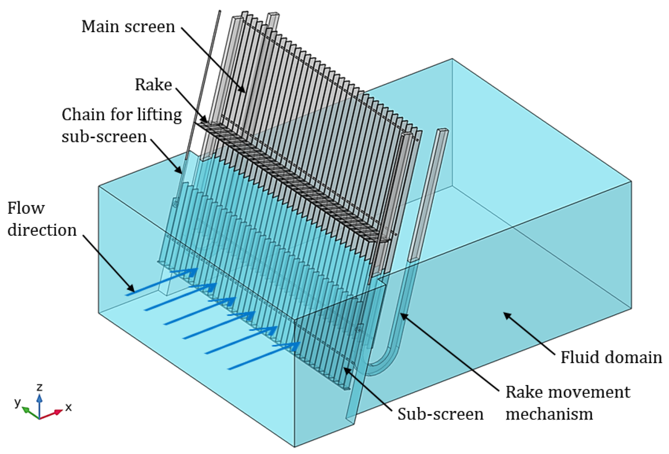
Figure 1 shows a 3D representation of the screening mechanism that comprises a fixed main screen, a sub-screen that can slide over the main screen in the vertical direction, and a rake, along with the rake movement mechanism. Water flows in the channel through the aperture of the screening mechanism, where any insoluble solid waste of an appreciable size is filtered from flowing into the plant. This accumulation results in flow separation in the downstream region, not only hurting the flow entering the wastewater treatment plant but also risking damaging the screening mechanism.
Any solid waste that floats on the water surface, such as twigs and plastic waste, accumulates in the upstream region of the screening system and tends to block the flow of water in the upper region of the channel. The model deals with this issue through a chain-driven rake system with gears. This system brings the rake downward along the posterior of the screen, comes to the front, and goes back up at the frontal region at certain times of the day, collecting and lifting the waste in the process. This waste can later be discarded once it is removed from the water surface. Similarly, any insoluble solid waste of an appreciable size that sinks to the channel floor, such as stones and heavy objects, accumulates in the upstream region of the screening system and tends to block the flow of water in the lower region of the channel. This issue is handled by a chain-driven gear system, which lifts the sub-screen after a certain bulk of solid waste is accumulated in this region. The mechanism can slide over the main screen due to the tilt of the screening. The sunken waste flows in bulk into the channel, where it can be discarded when the sub-screen is lifted.
Figure 2 presents the geometric configuration of the main screen, sub-screen, and rake system, and the values of the parameters have been summarized in Table 2. The screening mechanism is placed at location A, 0.75 m away from the inlet and oriented at an angle of 15° with the vertical cross-sectional plane through the channel. The number of bars on the main screen is 37, and on the sub-screen, it is 39, including bars on the extremes, whose height is 0.74 m. The aperture size of the screening mechanism is α = 0.075 m. Each finger of the rake has a breadth of 0.05 m and is spaced at 0.034 m to accommodate the bars. The total number of rake fingers is 36, and the width of each bar is 0.009 m. The flow channel under consideration has a width of w ch , c = 3.40 m in the upstream region of the WSM and a width of w ch , d = 3.10 m in the downstream region of the WSM. The physical dimensions and wastewater flow rates used in the present study were chosen based on the real flow conditions observed in a typical sewage channel in a WTP.
The dimensions of wastewater screening channels can vary widely. For instance, the design of a batik wastewater treatment plant includes units with dimensions ranging from 4.6 m in length, 2.3 m in width, and 4 m in height to 15 m in length, 15 m in width, and 1 m in height [20]. Likewise, the spacing in these components is set up to maintain a high capture efficiency for objects like twigs, plastic waste, stones, and heavy metal objects. As discussed in the introduction, the present study draws upon the work of Ali et al. [7]. However, the present study has several structural deviations from Ali et al., including but not limited to the fact that the analysis by Ali et al. was carried out in 2D, whereas in the present study, the analysis is carried out in 3D. Thus, a direct comparison of parameters between the present study and Ali et al. is not possible. Nonetheless, similar parameters have been compared in Table 3.
Two different configurations of the sub-screen on the screening mechanism were considered: when the sub-screen is fully lowered (εss = 0 m) and partially lowered (εss = 0.55 m). The fully lowered configuration was further studied for the rake at the posterior extreme (φ = −75°) and the vertical extreme (φ = 0°). The components comprise structural steels. The density (ρs), Young’s modulus (E), and Poisson’s ratio (η) of the structural steel used in the study are, respectively, set as 7850 (kg/m3), 200 (GPa), and 0.33 [21]. The water in this study had a density ( ρ f ) of 1000 kg/m3 and a viscosity ( μ f ) of 0.001 Pa·s. The supporting frame of the main screen and the sub-screen, along with the rake movement mechanism, were neglected because their inclusion into the model would be computationally expensive. Furthermore, structural and fluid mechanics results can be used to place the supports at appropriate locations and design the rake movement mechanism. The waste product is also neglected, because the scope of the present paper is to determine the flow separation due to the screening mechanism after the waste product is removed. The frequency of the rake appearance and the sub-screen lifting can later be optimized after considering the specifics of the respective installation site.

2.2. Mathematical Model

The interaction of the water flow with the rake and sub-screen models occurs at the interface shared by the two models. This phenomenon is called FSI, and the flow of the sewage water through the screening mechanism is an FSI problem. The present study uses the ALE approach with two-way coupling to solve such a problem.
In the ALE approach, first, the fluid flow is solved using the Navier–Stokes equation. The result obtained from the fluid flow solution is then used to calculate the structural deformation, and the fluid flow is solved using the Eulerian method. The coordinate system in the Eulerian method is fixed considering the computational domain. This frame of reference is called the spatial frame. The obtained solution is then fed into the solid mechanical study using the Lagrangian approach. The equations in the Lagrangian method are stated for small individual volumetric elements of the rigid body during deformation. Thus, the associated frame of reference moves with the individual particles during the rigid body deformation. The coordinate system moves with the rigid body as it deforms; thus, the location of the rigid object remains stationary, considering the Lagrangian coordinate system. This frame is called the material frame. The object appears undeformed in the Lagrangian frame [22,23].
The aforementioned theoretical approach may be used to address the FSI-based problems via two distinct forms of coupling: one-way and two-way coupling. The one-way coupling technique only accounts for the impacts of water flow on the rake and sub-screen models. In this technique, the structural impacts of the rake and sub-screen models do not have any influence on the flow of water. The structural features of the rake and sub-screen models are influenced by the water flow in the two-way coupling technique. Therefore, the water flow field is likewise influenced by the structural features of these solid models. The present methodology employs an iterative loop in order to facilitate the transfer of attributes from one domain to another. The fluid stresses derived from the sewage flow are used to generate mappings for the rake and sub-screen models. Subsequently, the ensuing displacements occurring in the structures are then sent back to the water flow.
Either one of the one- or two-way coupling approaches may be used to conduct the present study. To identify the more suitable approach between the two, we consider the operating conditions of the WSM and the availability of computational tools. In considering the operating conditions, we realize that the turbulence in the water flowing through the sewage, coupled with the fluctuation in the flow velocity and the disturbance due to the rake movement against the water flow, would induce oscillatory loading in the screening mechanism. Owing to this oscillatory loading, the structure is susceptible to the initiation and propagation of fatigue cracks. Once a fatigue crack is initiated, it may grow gradually with each loading cycle and cause structural damage over several cycles. Failing to consider the possibility of fatigue can be catastrophic, especially in structures that are susceptible to oscillatory loading conditions. In general, the two-way approach provides a more accurate solution and is thus able to capture minor disturbances in the flow accurately. In considering the computational tools available, we note that two types of two-way coupling approaches, namely, monolithic and partitioned approaches, are used in the industry for FSI simulation [24]. The monolithic approach requires an engineer to write a code that is specific to the physical problem being addressed, whereas the partitioned approach preserves the software modularity by coupling the existing flow and structural solvers. Therefore, the partitioned approach requires only the use of existing software, which is an advantage.
In summary, the ALE approach with two-way coupling is chosen based on the susceptibility of the screening mechanism to oscillatory flow conditions, requiring accurate fatigue crack analysis. This approach is preferred over one-way coupling due to its ability to capture minor flow disturbances accurately. Further, the analysis of the considered screening mechanism would require enhanced accuracy due to the oscillatory loading condition and subsequent susceptibility to fatigue cracks. Given that the two-way ALE approach can produce a more accurate result than its one-way counterpart whilst using already available software, adopting a two-way coupling approach to study the screening mechanism under the given loading conditions would be prudent.

2.2.1. Hydrodynamic Modeling

Firstly, a suitable model must be selected for the fluid flow problem by determining the Re of the open channel under consideration. The Reynolds number for the open channel is as follows [25]:
  Re = ρ f R h U μ f ,
where Rh is the hydraulic radius. This radius for the open channel is determined as follows:
R h = w ch h f w ch + 2 h f ,
where h f is the sewage water height (m), w ch is the sewage channel width (m), and U is the sewage inlet flow velocity (m/s).
The flow behavior in the open channel has the Reynold’s number range of approximately 81,000 to 240,000 and is therefore assumed to be turbulent [26]. The k–ω turbulence model is an appropriate choice for turbulent flows in an open channel with relatively high Reynolds numbers [27,28]. This model was, therefore, selected to solve the hydrodynamics of the present study. The following assumptions are provided, considering this model, to solve the hydrodynamics of the 3D model.
  • The flow throughout the open channel is considered Newtonian and incompressible [29].
  • The flow conforms to the principles of continuum theory, in which the governing equations are represented by the Navier–Stokes equations [30].
  • The Wilcox k–ω model, along with the two-way coupling ALE approach, is further assumed to be a suitable choice for open-channel flows with a Reynold’s number range of 81,000 to 240,000 [27,28].
  • The fluid slips at the channel wall and the interface at the screening mechanism are neglected.
Given the above assumptions, the flow in the sewage channel is governed by the following equations [25]:
  • Continuity equation:
ρ f ( . u f ) = 0 ,
where ρ f is the fluid density (kg/m3), and u f is the fluid velocity vector (m/s).
  • Momentum equation:
ρ f u f t + ρ f ( u f · ) u f + · [ p I + μ ( u f + ( u f ) T ) + f f ,
where p denotes the fluid pressure (Pa), f f denotes the body force (N/m3), and I denotes the identity matrix.
These equations provide a time evolution of the flow. Reynolds-averaged Navier–Stokes equations are obtained by manipulating the aforementioned equations. The vector representing velocity, denoted as u f in Equations (3) and (4), shall be substituted with U + u′. Here, U signifies the time-averaged velocity field in meters per second (m/s), while u′ symbolizes the perturbative velocity component, characterized by fluctuations in meters per second (m/s).
The k–ω turbulence model is dictated by a pair of equations governing the turbulent kinetic energy and the specific dissipation rate. This model demonstrates efficacy, particularly within scenarios involving flow separation, thus yielding accurate solutions. The equations dictating the behavior of turbulent kinetic energy (k) are stated as [31]
k t + u j k x j = τ ij u i x j β k ω + x j [ ( ν + σ k ν T ) k x j ] .
The symbols σk and σ ω represent the turbulent Prandtl numbers pertaining to kinetic energy and dissipation rate, respectively. k denotes turbulent kinetic energy (m2/s2), while ω signifies the dissipation rate measured in reciprocal seconds (1/s). Furthermore, ν T  represents the kinematic eddy viscosity measured in pascal seconds (Pa·s). Notably, constants σ ω and β* are assigned the values of 0.5 and 0.09, respectively [31]. In the k–ω turbulence model, the turbulent dissipation rate (ω) is
ω t + u j ω x j = α ω k τ ij u i x j β ω 2 + x j [ ( ν + σ ω ν T ) k x j ] ,
where the kinematic eddy viscosity ( ν T ) defined by the k–ω turbulence model is given as
ν T = k ω .
The boundary conditions for the hydrodynamic modeling involve a velocity inlet at the entry of the computational domain, an atmospheric pressure outlet at the exit, and an open boundary condition to the top surface to account for the full slip and for the possibility of water to escape from the top surface due to the decrease in the cross-sectional area in the downstream region of the channel. No slip boundary condition is applied to the walls and to the bottom surface of the channel.

2.2.2. Structural Mechanics Modeling

Deformation occurs when a structural mechanism experiences fluid flow due to the transfer of energy from fluid flow to solid, resulting in an FSI problem. The water flow (fluid flow) interacts with the rake and the sub-screen models (structural mechanics) at the common interface between the two models. The results of the fluid computation are used to compute the characteristics of solid mechanics. The following assumptions are presented for the structural mechanics model:
  • The main screen, the sub-screen, and the rake comprise a linear elastic domain that obeys the continuum theory [32].
  • The two-way coupling ALE approach is a more suitable choice than the one-way approach for the present problem, because the considered screening mechanism is expected to undergo oscillatory flow conditions and is therefore susceptible to fatigue cracks, suggesting the need for analysis with greater accuracy [33].
Below is the governing equation, implemented for the elastic material to determine its solid displacement [10]:
ρ s 2 u s t 2 = σ ij x j + ρ s f s ,
where us denotes the solid displacement (m), σij denotes the stress tensor component within the solid (N/m2), ρs denotes the solid density (kg/m3), and fs represents the body force components exerted on the solid (N/m3). The determination of σij emanates from the application of the constitutive equation of a Newtonian fluid. The cumulative force imparted onto the solid boundary by the fluid corresponds to the negative of the reactive force upon the fluid, as expressed by the following equation [34]:
f s = n · { p I + ( μ ( u f + ( u f ) T ) ) 2 3 μ ( · u f ) I } ,
where u f represents the velocity vector of the fluid medium in meters per second (m/s), while p denotes the fluid pressure (Pa). The identity matrix is represented by the symbol I. Additionally, the parameter fs pertains to the body force exerted upon the solid substance (N/m3). n designates the outward normal vector, which characterizes the orientation that is perpendicular to the boundary under consideration. The energy stored in the filtering mechanism due to the structural deformation is measured in the form of the strain energy density function W as follows [34]:
s ij = W ϵ ij   where   i , j   ϵ { 1 , 2 , 3 } ,
where sᵢⱼ and ϵᵢⱼ are the second Piola–Kirchhoff stress and the Green–Lagrange strain tensor components, respectively [35,36]. Lastly, a transformation of the force between the two coordinate systems is necessary, because the solid mechanics interfaces are defined in the material (undeformed) frame, whilst the Navier–Stokes equations are solved in the spatial (deformed) frame. Hence, a coordinate transformation is performed in the ALE model as follows:
f f = f s dv dV ,
where f f is the force on the fluid (N/m3), f s is the body force acting on the solid (N/m3), and dv and dV are the mesh element scale factors for the spatial and material (reference) frames, respectively. In the modeling of the structural mechanics, linear elastic materials are assumed for the WSM components. Boundary loads of fluid stresses are applied at the WSM components to simulate the interaction with fluid forces.

3. Numerical Method

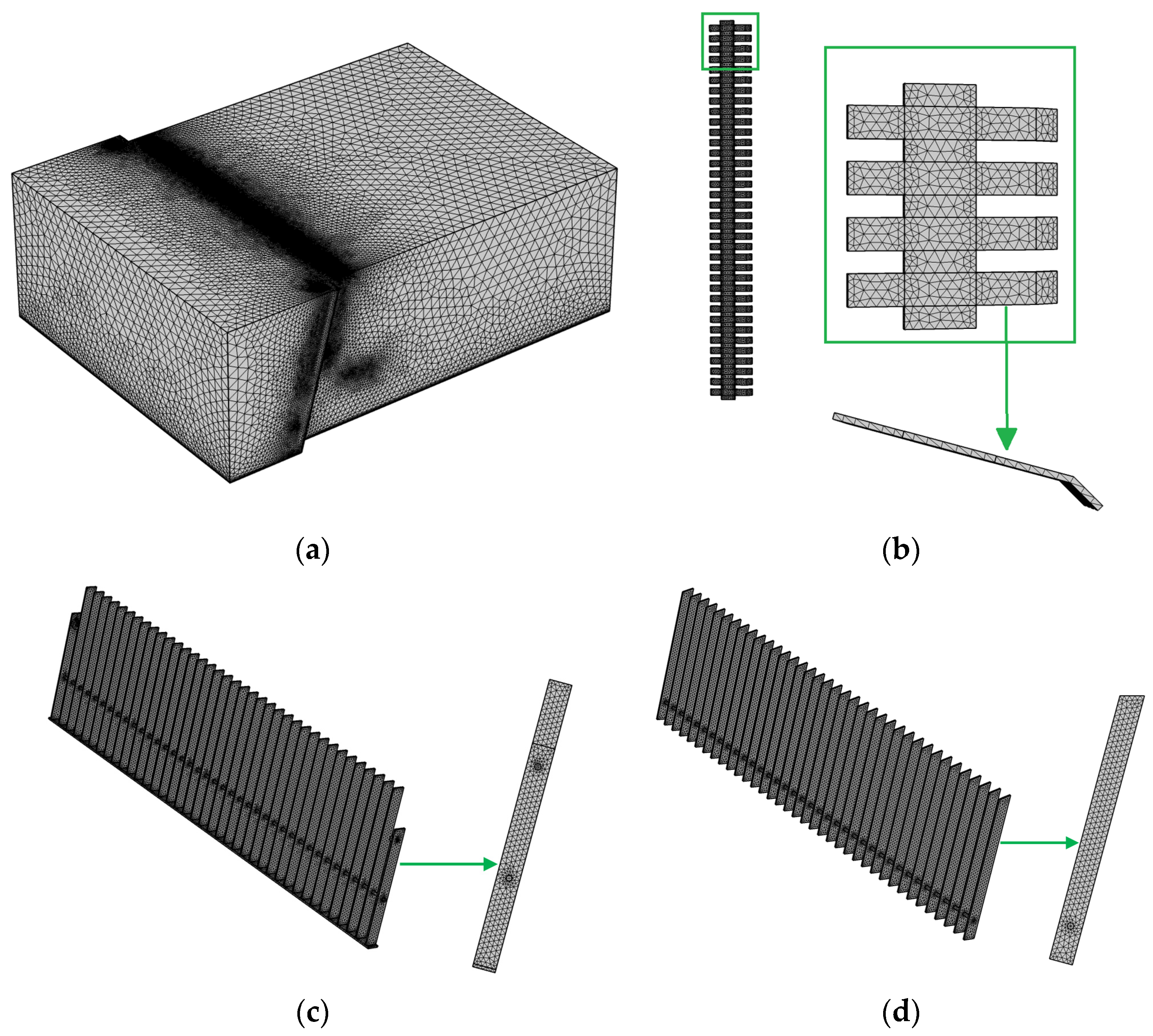
This study employs COMSOL Multiphysics (v5.5) to investigate the screening process by simulating the fluid–structure interaction of sewage water and components of the screening components. A time-dependent solver is employed to simulate the FSI interface of COMSOL Multiphysics with a k–ω turbulence model for 300 s and at a time step of 0.001 s. A built-in physics-controlled mesh, which consists of tetrahedral mesh elements, was used to discretize the computational domain. A boundary-layer mesh with a dense mesh along the FSI boundaries was used to capture the flow fields in these regions precisely. 
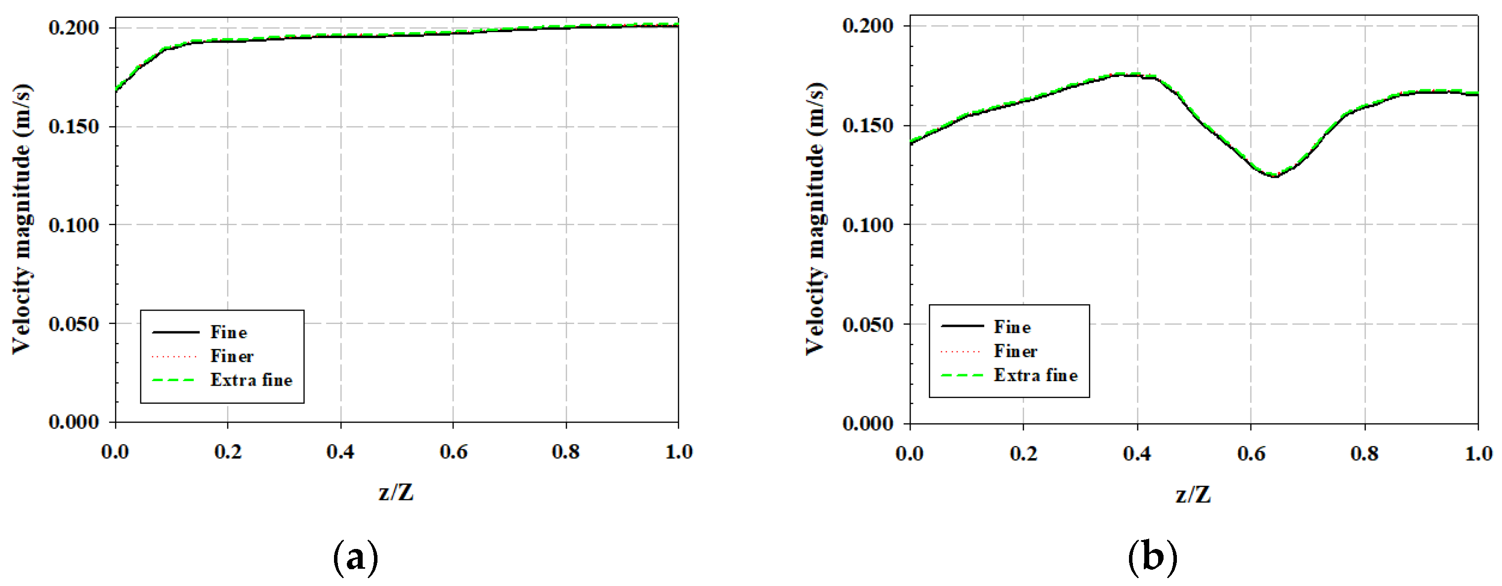
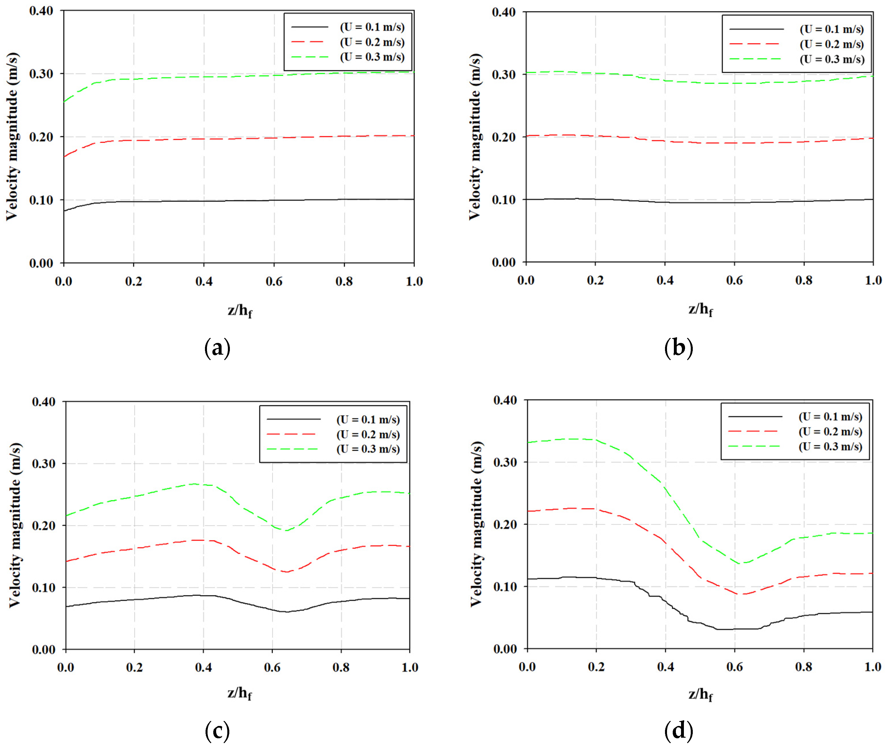
Figure 3 shows the grid details: (a) for the entire WSM channel, (b) rake, (c) sub-screen, and (d) main screen. A grid independence test was performed by varying the mesh elements with a factor of three under the same computational resources to ensure a high accuracy of results. Three different mesh sizes were employed in this study: fine (324,712 domains and 48,836 boundary elements), finer (1,187,146 domains and 129,646 boundary elements), and extra fine (4,176,976 domains and 355,447 boundary elements). The obtained results in terms of local velocity are plotted in the upstream region (at location C) and downstream region (at location D) of the WSM. The velocity is plotted at a distance (X-axis) of 0.5 m away from the WSM in the upstream region (location C) in Figure 4a. Similarly, the velocity is plotted at a distance (X-axis) of 0.5 m away from the WSM in the downstream region (location D) in Figure 4b. We note a minimal difference in the calculation of velocity magnitude at the upstream and downstream channels of the WSM at a flow velocity of 0.2 m/s. Therefore, a finer mesh (1,187,146 domains and 129,646 boundary elements) was adopted in further simulations to save computation time.

Model Validation

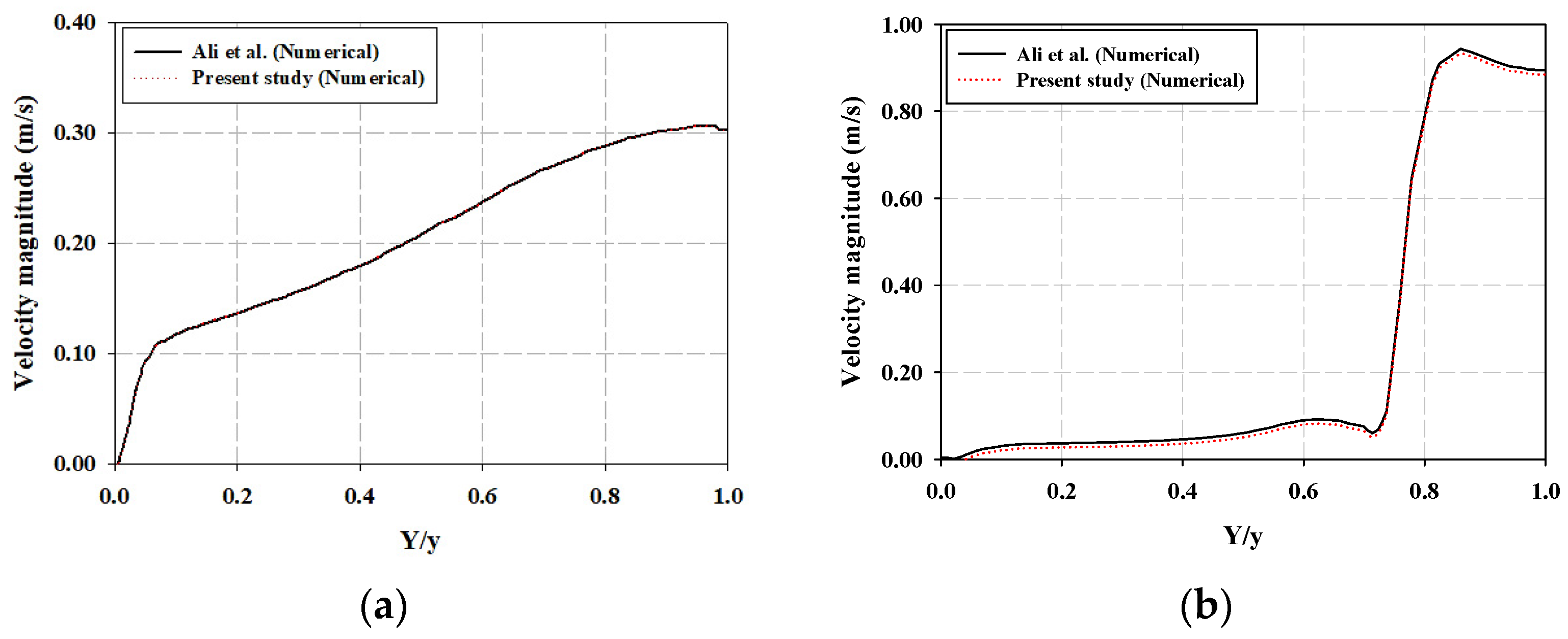
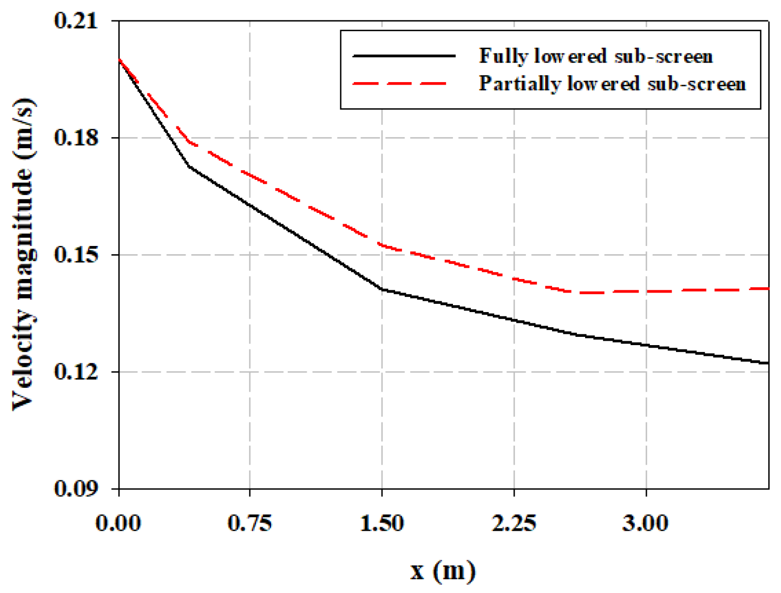
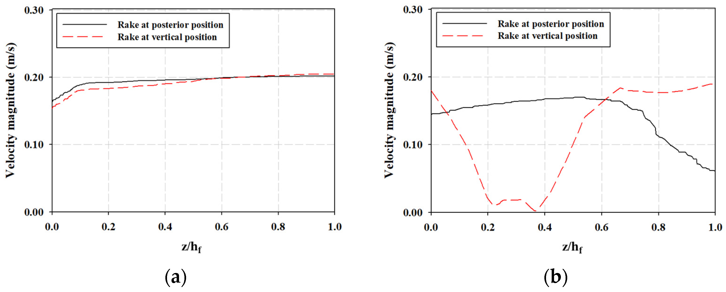
This study employed ALE two-way coupling to model the FSI between the water flow and the WSM components to analyze the screening process. For the validation of our approach, the results are compared with Ali et al. [7] in Figure 5 in terms of local velocity in the upstream and downstream channels for a 2D case of a WSM. The portions of the sewage channel before and after the WSM are called the upstream and downstream regions. The velocity is plotted at a distance (X-axis) of 0.5 m away from the WSM in the upstream region (location C) in Figure 5a. Similarly, the velocity is plotted at a distance (X-axis) of 0.5 m away from the WSM in the downstream region (location D) in Figure 5b. The consistency and quality of the results can be observed between the present study and [7]. However, a 2D model is not a reasonable solution for complex fluid flow problems, and a 3D model is a practical means to predict and visualize real physical phenomena. Specifically, a 3D model of the WSM provides a spatial map for the stress that is induced in the structure of the WSM, which highlights the locations where the stresses due to flow loading exceeded or were close to the maximum permissible values, which is impossible to identify with a 2D model. In a 3D model of a WSM, the spatial distribution of velocity and structure deformation helps identify the constraints and opportunities for design improvements.

4. Results and Discussion

4.1. Effect of the WSM on the Flow Distribution

The effect of the WSM on the flow distribution inside the sewage channel was investigated for certain representative positions of the sub-screen and the rake. Firstly, the fully lowered (εss = 0 m) and partially lowered (εss = 0.55 m) sub-screens are considered, whilst the rake is not operational and is thus above the water level. Moreover, the rake movement mechanism in the physical scenario will operate only whilst the sub-screen is fully lowered to avoid interference with the sub-screen components. Consequently, only the flow distribution due to the rake whilst the sub-screen is fully lowered was analyzed. Two different positions of the rake movement mechanism were considered: one with the rake in the vertical position (φr = 0) and the other with the rake at the posterior end of the WSM (φr = −75°).

4.1.1. Flow Distribution When the Rake Is Not Operational

The velocity distribution due to the WSM for the fully and partially lowered configurations of the sub-screen is considered, whilst the inlet velocity is maintained at 0.2 m/s. Figure 6a and b show the normalized velocity magnitude contours over the longitudinal vertical plane y = 0.1 m for the fully and partially lowered configurations of the sub-screen, respectively. The arrows in these plots represent the velocity magnitude: the shorter arrows indicate slower flow, and the longer arrows indicate faster flow. Fluid enters the channel in the positive x–direction and passes through the screening mechanism. An intense flow separation is observed between the upstream and the downstream regions of the WSM in either case. This flow separation is due to the drag in the direction opposite to the flow provided by the WSM.
In the papers by Szydłowski and by Dias and Vanden-Broeck, an obstruction in front of the flow results in head loss, thereby decreasing the area of the flow [37,38]. However, in the present study, we note a head increase as indicated by an increase in the z-component of the velocity field arrows in the downstream region in Figure 6a,b. In the present study, the cross-sectional area of the channel in the downstream region is lower than the cross-sectional area in the upstream region of the channel. This condition accommodates the possibility of head increase. We conclude that that the head increase caused by this reduction in the width offsets the head loss caused by the screening mechanism because mass conservation must be preserved.
Comparing Figure 6a,b, we note that the flow separation for the partially lowered configuration is significantly larger than the fully lowered configuration of the sub-screen. The sub-screen creates a high drag because it is in front of the main screen. Consequently, a large amount of fluid is directed below the lifted sub-screen, inducing an intense flow separation between the upper and lower regions of the sewage channel. The flow separation in the partially lowered sub-screen traverses until the end of the channel compared with the fully lowered sub-screen, in which the flow is uniform over the channel cross-section at the end of the channel. The effect of this flow separation on the components at the inlet of the WTP can be clarified in Figure 7a,b, which depict the arrows for the magnitude of the x-component of the velocity for the fully and partially lowered configurations of the sub-screen, respectively. The shorter arrows indicate slower flow, and the longer arrows indicate faster flow. These arrows are plotted over the longitudinal vertical plane y = 0.1 m. The velocity along the x-direction is fairly uniform over the channel cross-section at the end of the channel when the sub-screen is fully lowered. However, the x-component of the velocity assumes separation over the channel height towards the end of the channel. This phenomenon suggests an uneven stress distribution on the components at the inlet of the WTP, which should be established to account for this uneven stress distribution.
The flow treatment near the surface for the fully lowered configuration of the WSM is highlighted in Figure 6a. The water is slowed down in the immediate upstream vicinity of the sub-screen, followed by a rapid increase in velocity for the flow between the bars. The initial decrease in the flow velocity is due to the drag provided by the bars, whereas the subsequent increase in the flow velocity is due to the decrease in the cross-sectional area of the flow. As the flow moves ahead from the bars of the sub-screen, the flow velocity is again decreased because of an increase in the flow’s cross-sectional area. This decrease in the flow velocity is maintained in the space between the sub-screen and the main screen due to the drag provided by the main screen. As the fluid passes the main screen, a trend that is similar to that in the vicinity of the sub-screen is observed at a lower flow intensity due to the overall drag provided by the sub-screen. The flow treatment for the partially lowered configuration of the WSM is highlighted in Figure 6b. For the sub-screen in the partially lowered configuration, a trend that is similar to that for the sub-screen in the fully lowered configuration is observed. However, for the main screen in the partially lowered configuration, such an effect is negligible due to the drag caused by the sub-screen being slid in front of the main screen.
The effect of the inlet velocity on the flow distribution in the upstream and downstream regions inside the sewage channel are investigated in Figure 8a–d, which provide insights into the loading conditions on various WTP components in the vicinity of the WSM. Figure 8a shows the velocity in the region that is upstream of the WSM when the sub-screen is fully lowered. We note that at this location in the channel near the floor, the flow velocity is slightly below the inlet velocity, and as we move up the channel height, this velocity approaches the inlet velocity. However, in Figure 8b, which shows the velocity upstream of the WSM when the sub-screen is partially lowered, we note that the channel opening overcomes the flow resistance caused by the channel floor. This means that when the channel is partially lowered, there is a fully open passage at the bottom, which, according to the continuity equation (where a smaller flow cross-sectional area leads to a higher velocity), results in increased velocity near the channel floor, which counteracts the drag caused by the channel floor.
Figure 8c represents the downstream velocity when the sub-screen is fully lowered. We note in Figure 8c that when the sub-screen is fully lowered, there is a slight decrease in velocity compared to the upstream case in Figure 8a. This reduction is due to the resistance introduced by the WSM as water flows through it. As we move upwards from the channel floor in Figure 8c, the flow initially increases slightly because resistance at the floor decreases as we move upward. However, when the sub-screen and main screen overlap at a certain height, they create significant resistance, leading to a temporary decrease in velocity in that region. Beyond this overlap region, where only the main screen is present, the flow speed returns to the level observed below the overlap region. In Figure 8d, we notice that the velocity near the channel floor is high due to the continuity equation, which dictates that a smaller flow cross-sectional area results in a higher velocity. However, the velocity decreases significantly as we move upward when the main screen and sub-screen overlap. This decreased velocity continues as we move further upward. Thus, we note that Figure 8a–d provide insights into the potential stress variations that various components of the WTP may experience in the vicinity of WSM. The approximate speed of the debris is estimated by the average velocity decrease, as shown in Figure 9. For a constant inlet velocity of 0.2 m/s, the outlet velocity is reduced by 0.60% and 0.71% in the cases where the sub-screen is fully and partially lowered, respectively.

4.1.2. Flow Distribution When the Rake Is Operational

Figure 10a and b show the normalized velocity magnitude contours on the longitudinal vertical plane y = 0.1 m for the posterior and the vertical positions of the rake, respectively. These positions of the rake were chosen to represent the flow disturbance for the entire path of the rake because they create the most disturbance, that is, disruption is created as the rake enters the flow from behind. The vertical position was chosen because the rake front is highly exposed in this position. The arrows in Figure 10a,b represent the velocity field. The length of these arrows is proportional to the velocity magnitude—the shorter arrows indicate slower flow, and the longer arrows indicate faster flow. Fluid enters the channel in the positive x–direction at 0.2 m/s and passes through the screening mechanism. In either case, severe flow separation is observed in the vicinity of the rake during its operation time. However, any separation created by the rake is dampened by the time the fluid reaches the outlet. Therefore, the rake does not create a substantial non-uniformity over the cross-section of the channel at the outlet.
The effect of the rake operation on the components at the inlet of the WTP is further investigated in Figure 11a,b, which depict the magnitude of the x-component of the velocity over the y = 0.1 m plane for the posterior and the vertical positions of the rake, respectively. The shorter arrows indicate a slower flow, and the longer arrows indicate a faster flow. The velocity abruptly changes value at the outlet whilst the rake is operational, thereby suggesting an unsteady stress application on the components at the inlet of the WTP. Therefore, the design of the components at the inlet of the WTP should account for rapid velocity fluctuations throughout the rake operation. The flow profile in the immediate vicinity of the rake is highlighted in Figure 10a and b for the posterior (φr = −75°) and the vertical (φr = 0°) positions of the rake, respectively. Specifically, in Figure 10a, a wake region is developed near the posterior edge of the rake head whilst the rake is in the posterior position. No wake region is developed near the frontal edge of the rake head, thereby resulting in higher stresses in this region whilst the rake is in the posterior position. This trend is reversed when the rake is in the vertical position, as highlighted in Figure 10b. In this figure, a wake region is developed near the frontal edge of the rake head whilst the rake is in the vertical position, whereas no wake region is developed near the posterior edge of the rake head. This condition results in higher stresses on the posterior end of the rake head whilst the rake is in the vertical position.
The portions of the channel before and after the WSM are called the upstream and downstream regions. The velocity is plotted at a distance of (X-axis) 0.5 m away from the WSM in the upstream region (location C) in Figure 12a for the posterior and vertical positions of the rake. Similarly, velocity is plotted at a distance of (X-axis) 0.5 m away in the downstream channel of the WSM (location D) in Figure 12b for the posterior and vertical positions of the rake. This plot aims to compare the effects of the rake positions. The upstream plot shows that the velocity increases with the height of the fluid in the channel for both rake positions and therefore assumes maximum value near the surface of the sewage channel, as shown in Figure 12a. However, Figure 12b shows that the velocity profile in the downstream region is completely different from the profile in the upstream region in each case due to the flow obstruction offered by the rake and the screens. Notably, the velocity assumes a minimum value near the surface of the fluid in the sewage channel whilst the rake is in the posterior position. This assumption is introduced because the rake is an obstruction to the flow in the upward direction. Similarly, the vertical position of the rake is the main obstruction to the flow in the positive x-direction. This minimum velocity is assumed in the region behind the rake.

4.2. Effect of Flow Distribution on the WSM

4.2.1. Structural Deformation When the Rake Is Not Operational

The main screen, sub-screen, and the rake, along with the mechanisms that are used to lift the sub-screen and operate the rake, comprise a deformable material and thus would bend under an applied force. This deformation would negatively affect the screening process by disturbing the desired positions of the WSM components. Therefore, the deformation in the WSM components due to the flow distribution was investigated.
The normalized deformation contour plots of the main screen and the sub-screen due to the flow distribution when the sub-screen is fully lowered are presented for the inlet velocities of 0.1 and 0.3 m/s in Figure 13a,b and for the partially lowered case in Figure 13c and d, respectively. Notably, the main screen does not undergo significant deformation in any case due to the support of the wall at the lower end and near the top surface of the water. However, the fluid forces substantially deform the sub-screen, especially the upper-middle region. This deformation profile is similar in the fully and partially lowered cases.
The deformation of selected bars of the sub-screen, plotted on the FSI boundary of the sub-screen in Figure 14, for when the sub-screen is fully lowered is presented for the inlet velocities of 0.1 and 0.3 m/s in Figure 14a,b and for the partially lowered case in Figure 14c,d. The legend in the graph shows the selected bars of the sub-screen. B1, B6, B12, and B18 represent the 1st, 6th, 12th, and 18th bar of the sub-screen, respectively. h represents the displacement on the FSI boundary of the sub-screen starting at the bottom of the sub-screen, whereas hₛₛ represents the total length of the FSI boundary. The bending of the sub-screen is slightly increased for high flow rates. The higher flow velocity causes the drag force to be larger, resulting in a larger deformation of and high stresses in the WSM components. However, the intensity of deformation bending is unaffected whether the sub-screen is fully or partially lowered. It is noted that the present 3D study provides a comprehensive deformation profile across the entire bar set (B1, B6, B12, and B18), as depicted in Figure 14, and enables the examination of deformation in various sub-screen bars. This builds upon the analysis carried out by Ali et al. [7], whose similar study was focused on the 2D case. Figure 14 further shows that the spatial deformation rate of the sub-screen increases over the length of its bars. This finding reveals the favorability of a small height of the sub-screen.

4.2.2. Structural Deformation When the Rake Is Operational

Normalized deformation contour plots of the rake at the inlet velocity of 0.2 m/s are due to the flow distribution around the WSM, whilst the rake is at φr = −75° and φr = 0° as, respectively, as shown in Figure 15a,b. Thus, the fluid forces considerably deform the middle region of the rake. Therefore, the deformation shows high magnitudes in these regions. Moreover, the deformation in the case of φr = −75° is due to stress from the fluid below, whereas that for φr = 0° is due to stress on the rake from the front.
The deformation of select rake pins is plotted on the FSI boundary of the rake for the inlet velocity of 0.2 m/s for the posterior and vertical positions of the rake, as, respectively, as shown in Figure 16a,b. The legend in the graph shows the selected rake pins of the rake movement mechanism. R1, R6, R12, and R18 represent the 1st, 6th, 12th, and 18th rake pins of the rake movement mechanism, respectively. l represents the displacement of the FSI boundary on the rake pin, with the initial point at the tip of the pin, and lr represents the total length of the rake pin. The rake is significantly more deformed in the posterior position than it is in the vertical position. This finding is due to the flow behavior in the gap between the main screen and the sub-screen; that is, as the fluid passes this gap, the velocity of the fluid is increased right before the flow hits the rake, as shown in Figure 10a. However, the fluid interacting with the rake decelerated in the case of a vertical rake due to the passage of the sub-screen, which is located directly in front of the rake. Further, the present 3D study presents the deformation profile across the entire set of rake pins (R1, R6, R12, and R18), as shown in Figure 16. This enables the exploration of deformations across different rake pins, building upon the findings of Ali et al. [7], which focused on the 2D case.

4.2.3. Von Mises Stress on the Sub-Screen

The wastewater treatment system experiences significant stresses when the sewage fluid flows through the screens. Hence, it is imperative to retain the strength of the WSM in order to guarantee its ability to endure the fluid load conditions to which it is subjected. The present study employs the von Mises yield criterion to assess the potential yielding of the sub-screen and rake models under varying fluid forces. If the von Mises stress value of the sub-screen and the rake approaches the yield stress of the structural steel material (250 MPa) utilized for the components, it may be concluded that the WSM would experience failure when subjected to the specified load conditions [21]. The main contributing factors to the von Mises stress are abrupt changes or irregularities in the geometric model (fillets, holes, grooves, keyways, splines, tool marks, or manufacturing defects) and are known as stress concentrators; the model is likely to be fractured near these stress concentrators because of high stress [39,40,41].
The von Mises stresses on the FSI boundaries of the sub-screen were computed with the effects of the different inlet flow velocities and positions of the sub-screen. The orientation for the selected bars in Figure 17 is from the bottom to the top. The legend in the graph shows the selected bars of the sub-screen. B1, B6, B12, and B18 represent the 1st, 6th, 12th, and 18th bar of the sub-screen, respectively. h represents the displacement on the FSI boundary of the sub-screen with an initial point at the bottom. Furthermore, hₛₛ represents the total length of the FSI boundary on the sub-screen. A high von Mises stress was observed at the base of the sub-screen because of the corner acting as a stress concentrator. Similarly, high von Mises stress values also exist due to the basic structural support installed in the sub-screen. These phenomena are visible in the first and second peaks in Figure 17a,b for the fully lowered sub-screen and in Figure 17c,d for the partially lowered sub-screen. This contrasts with the 2D study conducted by Ali et al. [7], in which the von Mises stress on the sub-screen consistently decreased along a sub-screen bar from bottom to top. This observation stemmed from the fact that their sub-screen was mounted at the floor of the water stream and a horizontal supporting rod for the sub-screen was not considered in their geometry.
The presence of the two peaks in the present study can be attributed to specific features that are included in the present model. The first peak corresponds to the presence of corners aligning with the horizontal support bar at the bottom, while the second peak corresponds to the opening for a supporting rod which passes the through the sub-screen. The highest peaks are for 0.3 m/s for the fully lowered sub-screen at 5.5 and 5.9 MPa for the first and second peaks, respectively, which are lower than the material yield stress (250 MPa). Therefore, the sub-screen and the rake models are safe under applied fluid loading in the screening process.

4.2.4. von Mises Stress on the Rake

The von Mises stresses on the FSI boundaries of the rake were computed for the select rake pins for vertical and posterior positions of the rake. The stresses for the select pins at 0.2 m/s are shown in Figure 18, where l represents the displacement of the FSI boundary on the rake pin. The legend in the graph shows the selected rake pins of the rake movement mechanism. R1, R6, R12, and R18 represent the 1st, 6th, 12th, and 18th rake pins of the rake movement mechanism, respectively. The initial point of the FSI boundary on the rake is set at the tip of the pin. Furthermore, lr represents the total length of the rake pin. The two peaks in von Mises stress in each plot correspond to the stress concentrator (corner), wherein the rake teeth are attached to the rake head. When comparing the von Mises stress on the rake with the 2D analysis conducted by Ali et al. [7], their von Mises graphs exhibit rounded peaks, whereas the present study, which is conducted in 3D, shows pointed peaks. This can be attributed to the fact that the present study accounts for the full geometric complexity of the structure and thus allows for a more accurate representation of the stress distribution, particularly in regions where stress gradients are significant.
The von Mises is significantly higher in the posterior position than that in the vertical position. This finding is due to the flow behavior in the gap between the main screen and the sub-screen; that is, as the fluid passes this gap, the velocity of the fluid is increased right before the flow hits the rake, as shown in Figure 10a. However, the fluid interaction with the rake decelerated in the case of a vertical rake due to the passage in the sub-screen, which is located directly in front of the rake. The high peaks are for the posterior positions at 35.0 and 33.0 MPa, which are lower than the material yield stress of the structural steel (250 MPa). Thus, the sub-screen and rake models remain safe under the applied loading conditions.

5. Conclusions

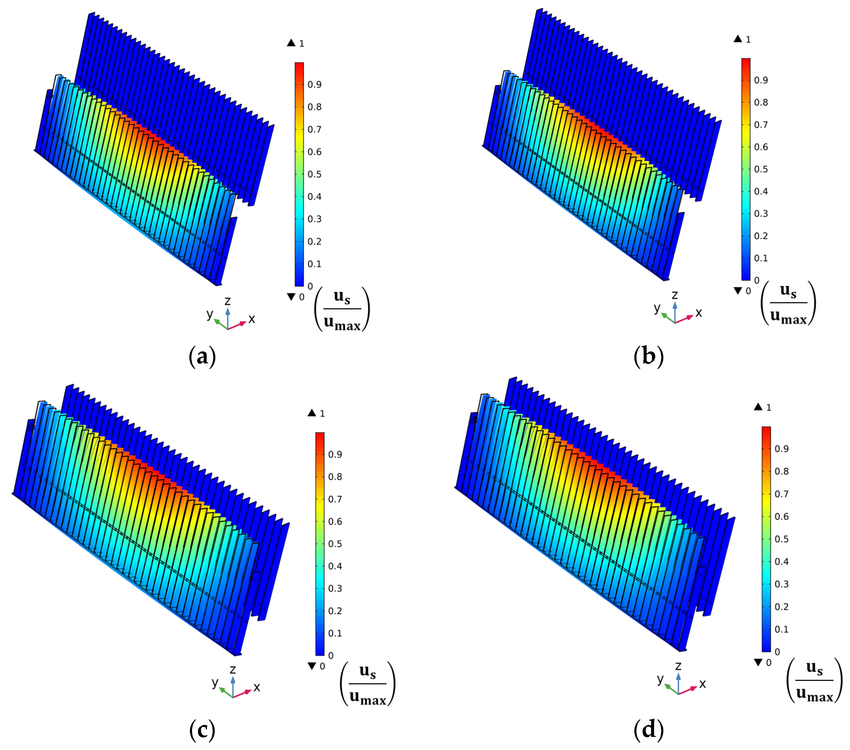
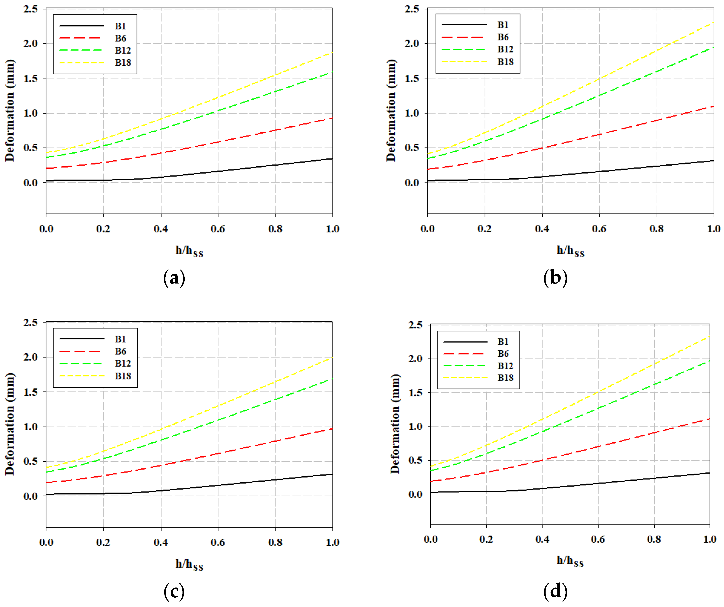
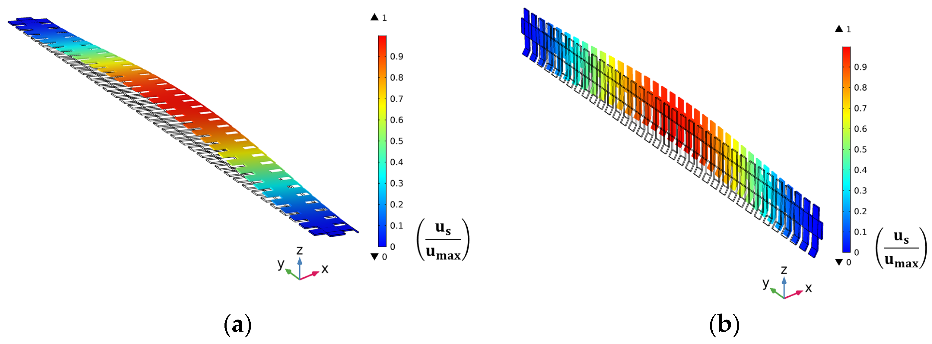
This paper computationally investigates the FSI between the WSM and sewage water flow to improve the screening process. A two-way coupling methodology was adopted to compute the flow of water through the WSM components. Two different configurations of the WSM were considered: one with the fully lowered sub-screen (εss = 0 m) and another where the sub-screen is partially lowered (εss = 0.55 m). Furthermore, two different stages of the rake movement were presented: one with the rake in the vertical position (φr = 0) and the other with the rake at the posterior end of the WSM (φr = −75°). The flow behavior in the upstream and downstream sections of the sewage channel was reported to examine the effect of the WSM on the water flow. The subsequent effect of water flow on the WSM components was also studied by computing the structural deformation of and the von Mises stresses in the WSM components. The main conclusions of the study are summarized as follows:
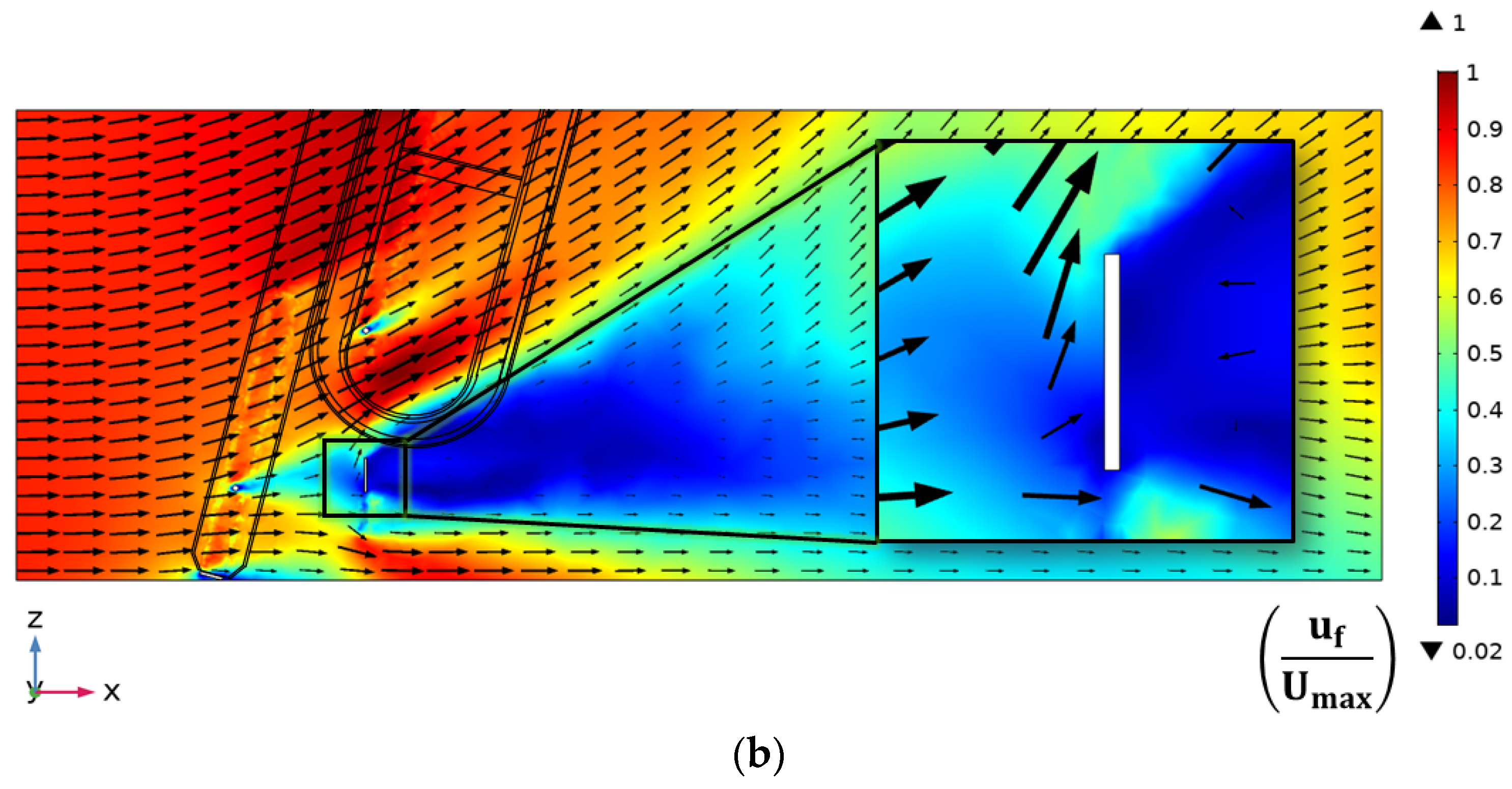
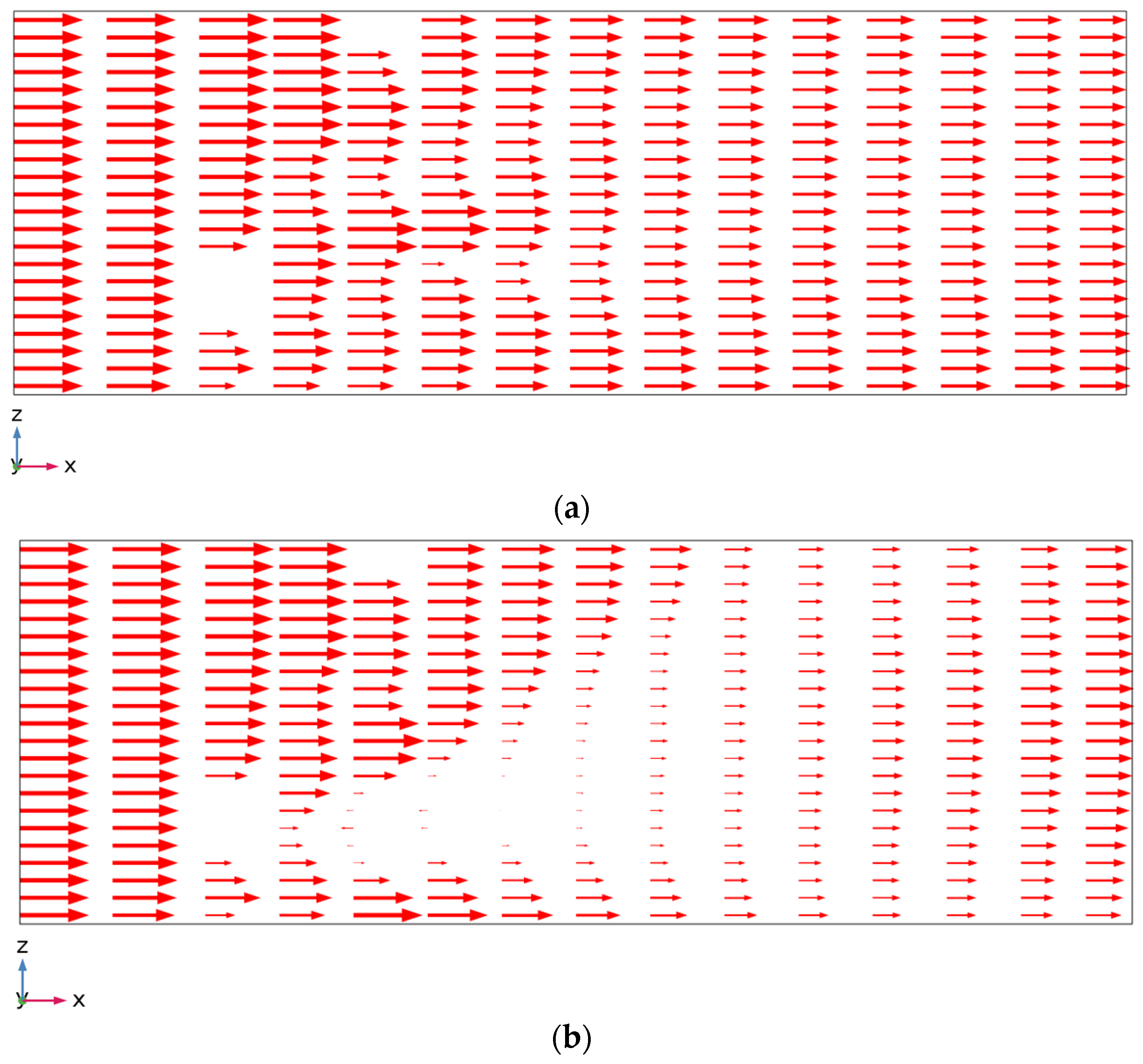
  • The flow distribution remains uniform after it passes through the WSM when the sub-screen is fully lowered and the rake is not operational. However, the flow separation in the case of a partially lowered sub-screen traverses until the end of the channel. Furthermore, the average cross-sectional velocity at the outlet is uniform when the rake is operational, but its magnitude fluctuates significantly. The average cross-sectional velocity at the outlet is reduced by 0.60% in the case where the sub-screen is fully lowered and by 0.71% in the case where the sub-screen is partially lowered.
  • The sub-screen is deformed especially at the upper mid-region. Moreover, the spatial rate of deformation of the sub-screen increases over the length of its bars. The fluid forces induce fluctuating deformation in the rake throughout its operation. Specifically, the deformation and von Mises stresses in the rake are significantly higher in the posterior position than in the vertical position.
  • The findings of the study have practical implications for engineers in material selection and structural design. Particularly, the significant fluctuations in the average cross-sectional velocity will result in unsteady stress application on the WSM components, especially when the rake movement mechanism is operational. Therefore, engineers must consider the dynamic loading conditions in their designs to avoid structural failures. Similarly, there are broader implications for wastewater treatment practitioners related to awareness about uneven stress distributions on the WSM, as this information will be crucial for the maintenance of WTP.
While the present study extends the available 2D research into 3D and attempts to present a comprehensive analysis of the screening components, it can be extended in several ways. For instance, the study did not include the supporting frame of the main screen and the sub-screen, as well as the rake movement mechanism, due to limitations in computational time. Including these components will help us understand the full interaction of all components in the WSM and thus improve the accuracy of the computations. Furthermore, the study primarily analyzed flow separation, structural deformation, and von Mises stresses. This focus leaves out other potential areas of interest, such as different types of solid waste that pass through the screen and chemical changes to the structural steel used due to a long-term interaction with water. These changes could affect the long-term operational efficiency and have implications for the sustainability of the WSM. Thus, future studies may include the additional WSM components, the analysis of solid waste, and the investigation of the sustainability and environmental aspects of the WSM.

Author Contributions

Conceptualization, S.A., S.A.M. and C.-W.P.; methodology, S.A. and S.A.M.; software, S.A., S.A.M. and C.-W.P.; validation, S.A.; formal analysis, S.A. and S.A.M.; investigation, S.A. and S.A.M.; resources, H.-B.C., D.-W.C. and C.-W.P.; data curation, S.A. and S.A.M.; writing—original draft preparation, S.A. and S.A.M.; writing—review and editing, S.A., S.A.M. and C.-W.P.; visualization, S.A. and S.A.M.; supervision, C.-W.P. All authors have read and agreed to the published version of the manuscript.

Funding

This work was supported by the National Research Foundation of Korea grant, funded by the Korean government (MSIT, No. RS-2023-00208673).

Data Availability Statement

The data used to support the findings of this study are included within the article.

Acknowledgments

The authors would like to thank the initiation of the I-ENTEC Co., Ltd.

Conflicts of Interest

Author Hyeon-Bae Chae and Du-Whan Choi were employed by the company I-ENTEC Co., Ltd. The authors declare no conflicts of interest. The funders had no role in the design of the study; in the collection, analyses, or interpretation of data; in the writing of the manuscript; or in the decision to publish the results.

Nomenclature

EYoung’s modulus (GPa)ρ density [kg/m3]
fbody force [N/m3]σij stress tensor in a solid [N/m2]
hheight [m]Σk Prandtl number for kinetic energy
Iidentity matrix σ ω Prandtl number for dissipation rate
kturbulent kinetic energy [m2/s2]ωdissipation rate [1/s]
l length [m]Subscripts
ppressure [Pa]b individual bar
rradius [m]cupstream region of the WSM
Re Reynolds numberchsewage channel
Rhhydraulic radius [m]ddownstream region of the WSM
sclearance [m]f fluid
tthickness [m]ms main screen
U sewage inlet flow velocity [m/s]r rake
Utime-averaged velocity field [m/s]s solid
Umaxmaximum velocity in the channel [m/s]ss sub-screen
u′fluctuating component of velocity [m/s]Coordinates
u f fluid velocity vector [m/s]x,y,zglobal coordinate system
umaxmaximum solid displacement [m]φ clockwise angle from –z rotation axis
ussolid displacement [m]ε vertical displacement
W strain energy density function
wwidth [m]
Greek symbols
ηPoisson’s ratio
ν T kinematic eddy viscosity [Pa·s]
θslant angle of the WSM
μ dynamic viscosity [Pa·s]

References

  1. Gupta, V.K.; Ali, I.; Saleh, T.A.; Agarwal, S. Chemical treatment technologies for waste-water recycling—An overview. RSC Adv. 2012, 2, 6380–6388. [Google Scholar] [CrossRef]
  2. Novak, M.; Horvat, P. Mathematical Modelling and Optimisation of a Waste Water Treatment Plant by Combined Oxygen Electrode and Biological Waste Water Treatment Model. Appl. Math. Model. 2012, 36, 3813–3825. [Google Scholar] [CrossRef]
  3. Sharpe, D.E.; Kirkbride, T.W. Storm-Water Overflows: The Operation and Design of a Stilling Pond. Proc. Inst. Civ. Eng. 1959, 13, 445–466. [Google Scholar] [CrossRef]
  4. Newton, C.; Wilson, J.P. Recirculating Gravel Filters: High-Performance Treatment at Low Cost for Two Small Communities. Water Sci. Technol. 2008, 58, 1245–1251. [Google Scholar] [CrossRef] [PubMed]
  5. Osei, K.; Andoh, R. Optimal Grit Removal and Control in Collection Systems and at Treatment Plants. In Proceedings of the World Environmental and Water Resources Congress 2008, Honolulu, HI, USA, 12–16 May 2008; Volume 316, pp. 1–7. [Google Scholar]
  6. Finger, R.E.; Parrick, J. Optimization of grit removal at a wastewater plant. J. Water Pollut. Control Fed. 1980, 52, 2106–2116. [Google Scholar]
  7. Ali, H.; Kim, K.W.; Bang, S.G.; Chae, H.B.; Shin, S.W.; Park, C.W. Numerical Modeling of Fluid–Structure Interaction between Sewage Water Flow and Bar Screen to Improve the Screening Process. Water Environ. J. 2019, 33, 560–573. [Google Scholar] [CrossRef]
  8. Pavlov, V. Travelling Waste Water Screen Sizing and Performance, UK. J. Environ. Eng. Sci. 2018, 13, 108–116. [Google Scholar] [CrossRef]
  9. Meeds, B.; Balmforth, D.J. Full-Scale Testing of Mechanically Raked Bar Screens. Water Environ. J. 1995, 9, 614–620. [Google Scholar] [CrossRef]
  10. Anderson, R.W.; Elliott, N.S.; Pember, R.B. An arbitrary Lagrangian-Eulerian Method with Adaptive Mesh Refinement for the Solution of the Euler Equations. J. Comput. Phys. 2004, 199, 598–617. [Google Scholar] [CrossRef]
  11. Duarte, F.; Gormaz, R.; Natesan, S. Arbitrary Lagrangian-Eulerian Method for Navier-Stokes Equations with Moving Boundaries. Comput. Methods Appl. Mech. Eng. 2004, 193, 4819–4836. [Google Scholar] [CrossRef]
  12. Liu, Z.G.; Liu, Y.; Lu, J. Fluid-Structure Interaction of Single Flexible Cylinder in Axial Flow. Comput. Fluids 2012, 56, 143–151. [Google Scholar] [CrossRef]
  13. Clair, G.; Ghidaglia, J.M.; Perlat, J.P. A Multi-Dimensional Finite Volume Cell-Centered Direct ALE Solver for Hydrodynamics. J. Comput. Phys. 2016, 326, 312–333. [Google Scholar] [CrossRef]
  14. Zheng, X.; Karniadakis, G.E. A Phase-Field/ALE Method for Simulating Fluid–Structure Interactions in Two-Phase Flow. Comput. Methods Appl. Mech. Eng. 2016, 309, 19–40. [Google Scholar] [CrossRef]
  15. Spellman, F.R. Spellman’s Standard Handbook for Wastewater Operators: Volume I, Fundamental Level, 2nd ed.; CRC Press: Boca Raton, FL, USA, 2010; ISBN 9781439818855. [Google Scholar]
  16. Pinheiro, D.M.; Ratusznei, S.M.; Rodrigues, J.A.D.; Zaiat, M.; Foresti, E. Fluidized ASBR Treating Synthetic Wastewater: Effect of Recirculation Velocity. Chem. Eng. Process. Process Intensif. 2008, 47, 184–191. [Google Scholar] [CrossRef]
  17. Lee, Y.H.; Lee, W.H.; Kim, K.W.; Ali, H.; Cheema, T.A.; Kwak, M.K.; Park, C.W. Numerical Investigation of Stress–Strain and Deformation Characteristics Imposed upon Automatic Screener Rakes. Mater. Res. Innov. 2014, 18, S5-17–S5-20. [Google Scholar] [CrossRef]
  18. Roth, A.; Jafarnejad, M.; Schwindt, S.; Schleiss, A. Design Optimization of Permeable Sediment Traps for Fluvial Bed Load Transport. E3S Web Conf. 2018, 40, 3009. [Google Scholar] [CrossRef]
  19. Schalko, I.; Weitbrecht, V. Wood Blockage and Sediment Transport at Inclined Bar Screens. J. Hydraul. Res. 2022, 60, 164–172. [Google Scholar] [CrossRef]
  20. Purwaningrum, S.I.; Syarifuddin, H.; Nizori, A.; Wibowo, Y.G. Wastewater Treatment Plant Design for Batik Wastewater with Off-Site System Method in Ulu Gedong Sub-District, Jambi City. J. Presipitasi Media Komun. dan Pengemb. Tek. Lingkung. 2023, 20, 153–164. [Google Scholar] [CrossRef]
  21. Beer, F.; Johnston, R.E.; DeWolf, J.; Mazurek, D. Mechanics of Materials, 6th ed.; McGraw-Hill: New York, NY, USA, 2011. [Google Scholar]
  22. COMSOL Inc. CFD Documentation; COMSOL Inc.: Burlington, MA, USA, 2020. [Google Scholar]
  23. Souli, M.; Zolesio, J.P. Arbitrary Lagrangian-Eulerian and Free Surface Methods in Fluid Mechanics. Comput. Methods Appl. Mech. Eng. 2001, 191, 451–466. [Google Scholar] [CrossRef]
  24. Ha, S.T.; Ngo, L.C.; Saeed, M.; Jeon, B.J.; Choi, H. A Comparative Study between Partitioned and Monolithic Methods for the Problems with 3D Fluid-Structure Interaction of Blood Vessels. J. Mech. Sci. Technol. 2017, 31, 281–287. [Google Scholar] [CrossRef]
  25. Munson, B.R.; Young, D.F.; Okiishi, T.H. Fundamentals of Fluid Mechanics; John Wiley & Sons: Hoboken, NJ, USA, 1994; ISBN 0471305855. [Google Scholar]
  26. Chow, V. Te Open Channel Hydraulics, 1st ed.; McGraw-Hill: New York, NY, USA, 1959. [Google Scholar]
  27. Wilcox, D.C. Reassessment of the Scale-Determining Equation for Advanced Turbulence Models. AIAA J. 1988, 26, 1299–1310. [Google Scholar] [CrossRef]
  28. Wilcox, D.C. Simulation of Transition with a Two-Equation Turbulence Model. AIAA J. 1994, 32, 247–255. [Google Scholar] [CrossRef]
  29. Henderson, F.M. Open Channal Flow; Macmillan Publishers Company: New York, NY, USA, 1966. [Google Scholar]
  30. Batchelor, G.K. An Introduction to Fluid Dynamics; Cambridge University Press: Cambridge, UK, 2000; Volume 12. [Google Scholar]
  31. Wilcox, D.C. Turbulence Modelling for CFD, 3rd ed.; DCW Industries: La Canada, CA, USA, 2006; ISBN 9781928729082. [Google Scholar]
  32. Timoshenko, S.P.; Goodier, J.N. Theory of Elasticity; McGraw-Hill: New York, NY, USA, 1970. [Google Scholar]
  33. Hughes, T.J.R.; Franca, L.P. A New Finite Element Formulation for Computational Fluid Dynamics: VII. The Stokes Problem with Various Well-Posed Boundary Conditions: Symmetric Formulations that Converge for All Velocity/Pressure Spaces. Comput. Methods Appl. Mech. Eng. 1987, 65, 85–96. [Google Scholar] [CrossRef]
  34. Zienkiewicz, O.C.; Taylor, R.L.; Fox, D. The Finite Element Method for Solid and Structural Mechanics, 7th ed.; Butterworth-Heinemann: Oxford, UK, 2013; ISBN 9781856176347. [Google Scholar]
  35. Ciarlet, P.G. Mathematical Elasticity I; SIAM publishes: Philadelphia, PA, USA, 1988; ISBN 0444702598. [Google Scholar]
  36. Zhang, Q.; Song, C. Multiphysics Modeling—Numerical Methods and Engineering Applications; Elsevier: Amsterdam, The Netherlands, 2016; ISBN 9780124077096. [Google Scholar]
  37. Szydłowski, M. Numerical simulation of open channel flow between bridge piers. TASK Q. 2011, 15, 271–282. [Google Scholar]
  38. Dias, F.; Vanden-Broeck, J.M. Open Channel Flows with Submerged Obstructions. J. Fluid Mech. 1989, 206, 155–170. [Google Scholar] [CrossRef]
  39. Frantziskonis, G.; Deymier, P. Surface Effects at the Nanoscale Significantly Reduce the Effects of Stress Concentrators. Probabilistic Eng. Mech. 2006, 21, 277–286. [Google Scholar] [CrossRef]
  40. Frantziskonis, G.; Deymier, P. The Effects of Stress Concentrators on Strength of Materials at Nanoscale: A Molecular Dynamics Study. Mech. Res. Commun. 2006, 33, 352–358. [Google Scholar] [CrossRef]
  41. Rosenberg, G.; Sinaiová, I.; Juhar, Ľ. Effect of Microstructure on Mechanical Properties of Dual Phase Steels in the Presence of Stress Concentrators. Mater. Sci. Eng. A 2013, 582, 347–358. [Google Scholar] [CrossRef]
Figure 1. A 3D representation of the WSM.
Applsci 14 00076 g001
Figure 2. Geometric representation of the WSM with the sub-screen lifted at the vertical displacement of εss from the channel floor and the rake oriented at the angular displacement of φr from the vertical cross-sectional plane; A represents the location of the WSM in the channel cross-section. C represents the cross-sectional plane at c = 0.5 m upstream of the WSM, and D represents the cross-sectional plane at d = 0.5 m downstream of the WSM.
Applsci 14 00076 g002
Figure 3. Mesh configuration: (a) for the entire WSM channel, (b) rake, (c) sub-screen, and (d) the main screen.
Applsci 14 00076 g003
Figure 4. Mesh independence test at a flow velocity of 0.2 m/s for (a) upstream region (location C) and (b) downstream region (location D).
Applsci 14 00076 g004
Figure 5. Comparison of present technique with the study of Ali et al. [7]: (a) upstream region (location C) and (b) downstream region (location D).
Applsci 14 00076 g005
Figure 6. Normalized velocity contour plot around the WSM at y = 0.1 m for the inlet velocity of 0.2 m/s when the sub-screen is (a) fully lowered and (b) partially lowered; the arrows represent the velocity magnitude at the trailing points.
Applsci 14 00076 g006
Figure 7. Velocity profile along the x-direction for the inlet velocity of 0.2 m/s when the sub-screen is (a) fully lowered and (b) partially lowered; the arrows represent the horizontal component of the velocity at the trailing points.
Applsci 14 00076 g007aApplsci 14 00076 g007b
Figure 8. Effects of different inlet velocities and sub-screen positions: upstream velocity (at location C) when the sub-screen is (a) fully lowered and (b) partially lowered; downstream velocity (at location D) when the sub-screen is (c) fully lowered and (d) partially lowered.
Applsci 14 00076 g008
Figure 9. Variation in flow average cross-sectional velocity along the flow direction at 0.2 m/s.
Applsci 14 00076 g009
Figure 10. Normalized velocity contour plots at y = 0.1 m for an inlet velocity of 0.2 m/s when the rake is operational and (a) φr = −75°; (b) φr = 0°; the view of the rake has been magnified, and the arrows represent the velocity magnitude at the trailing points.
Applsci 14 00076 g010aApplsci 14 00076 g010b
Figure 11. Velocity profile along the x-direction for the inlet velocity of 0.2 m/s when the rake is operational and (a) φr = −75°; (b) φr = 0°; the arrows represent the horizontal component of the velocity at the trailing points.
Applsci 14 00076 g011
Figure 12. Effects of rake on the velocity magnitude at posterior position (φr = −75°) and vertical position (φr = 0°) in the (a) upstream region (location C) and (b) downstream region (location D).
Applsci 14 00076 g012
Figure 13. Normalized deformation contour plots of the main screen and sub-screen when the sub-screen is fully lowered for (a) U = 0.1 m/s and (b) U = 0.3 m/s and partially lowered for (c) U = 0.1 m/s and (d) U = 0.3 m/s.
Applsci 14 00076 g013
Figure 14. Deformation of the sub-screen bars when the sub-screen is fully lowered for (a) U = 0.1 m/s (b) U = 0.3 m/s and partially lowered for (c) U = 0.1 m/s and (d) U = 0.3 m/s.
Applsci 14 00076 g014
Figure 15. Normalized deformation contour plots of the rake at U = 0.2 m/s for (a) φr = −75° and (b) φr = 0°.
Applsci 14 00076 g015
Figure 16. Deformation of the different rake pins at U = 0.2 m/s for (a) φr = −75° and (b) φr = 0°.
Applsci 14 00076 g016
Figure 17. von Mises stress profile on the sub-screen bars when the sub-screen is fully lowered at (a) U = 0.1 m/s and (b) U = 0.3 m/s and for partially lowered at (c) U = 0.1 m/s and (d) U = 0.3 m/s.
Applsci 14 00076 g017
Figure 18. von Mises stress profile on the rake pins at U = 0.2 m/s for (a) φr = −75° and (b) φr = 0°.
Applsci 14 00076 g018
Table 1. Comparison of aspects of the present study with Ali et al. [7].
AspectAli et al. [7]Present Study
Dimensionality (2D vs. 3D)2D3D
Sub-screen attachment to the floorPivotAscendable
Sub-screen angle relative to the floorAdjustableFixed
Stress considerationPlane stresses (2D)3D stresses
Flow impingement on the sub-screenSingle bar (2D)Entire span of sub-screen (3D)
Rake pin considerationSingle rake pin (2D)Entire span of the rake (3D)
Table 2. Geometric configuration of the screening mechanism.
DimensionsValue
l ch 4.500 m
w ch , c 3.400 m
w ch , d 3.110 m
a0.750 m
c0.500 m
d0.500 m
h f 1.550 m
hss0.950 m
hms0.880 m
t b 0.075 m
s0.210 m
l r , 1 0.290 m
l r , 2 0.050 m
l r ( = l r , 1 + l r , 2 ) 0.340 m
tr0.008 m
r0.300 m
sr0.060 m
θ15°
εss{0 m, 0.55 m}
φr{−75°, 0°}
Table 3. Comparison of parameters of the present study with Ali et al. [7].
ParameterAli et al. [7]Present Study
Channel width4.2 m3.40 m upstream, 3.11 m downstream
Thickness of the sub-screen bar0.06 m0.075 m
Sub-screen position{0°, 15°}fully lowered, partially lowered
Sub-screen height1.11 m0.95 m
Number of bars on the main screenN/A37
Number of bars on the sub-screenN/A39
Number of rake pinsN/A36
Rake position{15°, 105°}{−75°, 0°}
Rake length0.33 m0.34 m
Disclaimer/Publisher’s Note: The statements, opinions and data contained in all publications are solely those of the individual author(s) and contributor(s) and not of MDPI and/or the editor(s). MDPI and/or the editor(s) disclaim responsibility for any injury to people or property resulting from any ideas, methods, instructions or products referred to in the content.

