Abstract
Due to the extreme temperatures inside the combustion chambers of liquid propellant rocket engines, the walls of the combustion chamber and the nozzle are cooled by either the fuel or the oxidizer in what is known as regenerative cooling. This study presents an indigenous computational tool developed for the analysis of heat transfer in regenerative cooling of such rocket engines. The developed tool incorporates a one-dimensional (1-D) combustion analysis to calculate the thermophysical properties of the combustion gas. Basic engine properties were calculated and used to generate a thrust chamber profile based on a bell-shaped nozzle. The hot gas side was analyzed using 1-D isentropic flow assumptions, along with heat transfer correlations. The coolant side was evaluated using the hydraulic analysis in the axial direction and the heat transfer analysis in the radial direction. Thermophysical properties and the phase of the coolant were determined using the given property tables and the instantaneous state of the coolant. This flexible and computationally less demanding tool was used to analyze two small-scale engines utilizing liquid hydrocarbon fuels, which are used in modern rocket propulsion. The wall cooling analyses of a liquid oxygen (LOX)/liquid methane (LCH4) engine and a liquid oxygen (LOX)/liquid propane (LC3H8) engine are presented. Fuel and oxidizer were used separately as coolants for both engines, and both of them experienced phase change. Results reveal the advantage of the high mass flow rate of the oxidizer in cooling performance. In addition, the results of this study show that the cooling of the LOX/LC3H8 engine is somewhat more challenging compared to the LOX/LCH4 engine.
1. Introduction
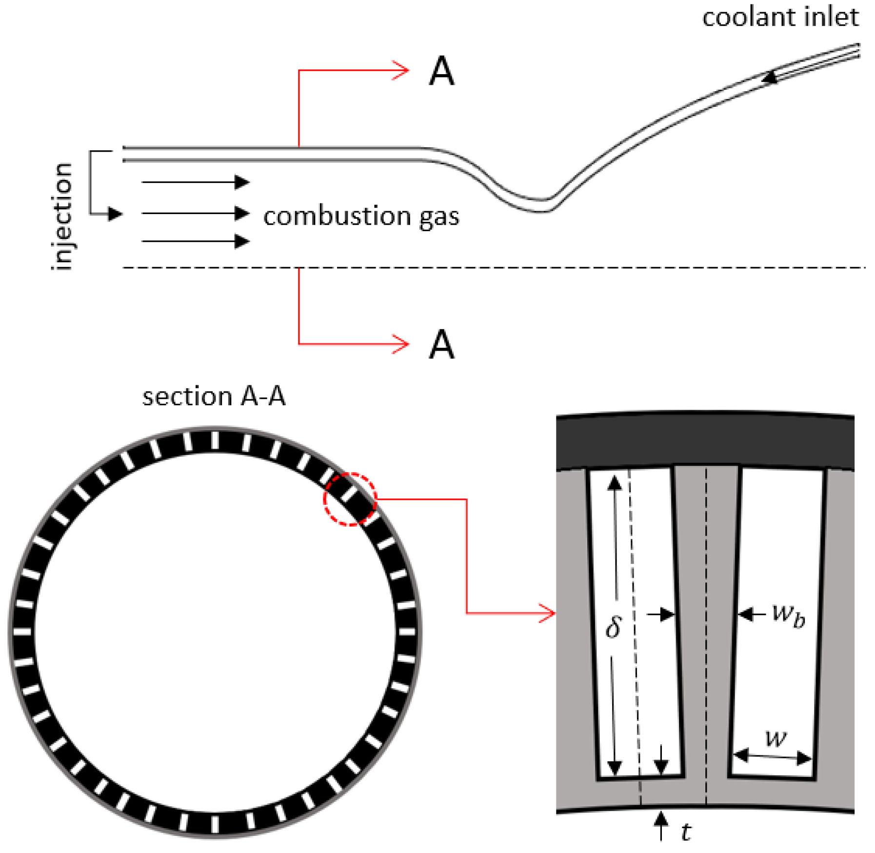
Cooling of the combustion chamber and the nozzle is one of the most important challenges in the development of liquid propellant rocket engines and should be addressed in early design phases. Due to the high combustion temperatures, reaching 3500 K, in liquid propellant rocket engines, most known engineering materials will melt if a cooling method is not employed. Some engine cooling methods that have been used so far include ablative cooling, radiative cooling, film cooling, and most commonly, regenerative cooling. Regenerative cooling, schematized in Figure 1, is typically achieved using cooling channels machined on the outer wall of the thrust chamber, through which the rocket propellant, often fuel, of preferably high heat capacity flows as the coolant, thereby regaining some of the otherwise lost energy. The rate of heat transfer in such engines is in the order of tens of mega-Watts per square meter, and the thrust chambers are manufactured from a metal of high thermal conductivity, mostly copper alloys, so as to not constitute a high thermal resistance in the thermal path from the hot gas to the coolant [1,2].
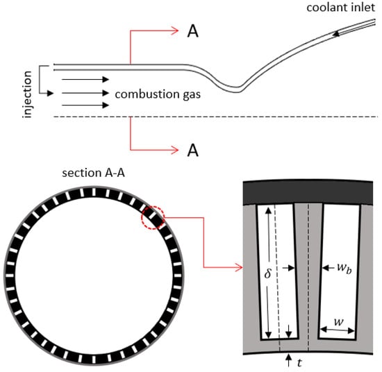
Figure 1.
Schematics of a regeneratively cooled liquid rocket engine and its cooling channels.
In the early design phase, engineers may desire to assess whether the selected fuel is sufficient for regenerative cooling in terms of thermophysical properties and mass flow rate, or whether an additional cooling method such as film cooling should be combined with regenerative cooling. In addition, occasionally, oxidizer could be preferred as the coolant, as in the case of some liquid oxygen (LOX)/kerosene engines [3]. Furthermore, in the early design phase, one could desire to have preliminary information about the size and the shape of the cooling channels, as it influences the overall design and manufacturing. As the development process progresses, detailed analyses regarding the engine cooling will have to be conducted; however, the early decisions should be on time and logical, so as to not result in any inconvenience or lost time in ensuing phases. Therefore, simple modelling tools for regenerative cooling of liquid propellant rocket engines are invaluable in early design phases. Such tools could be used to evaluate the suitability of regenerative cooling, and to find the optimum channel number and cross section as a starting point.
Heat transfer in liquid propellant rocket engines has been extensively studied in the literature. RTE [4] and TDK [5] are two well-known tools for the thermal analysis of rocket engines that are developed using older programming methods. Despite the utilization of these tools in different studies [6,7,8], simpler and more practical modelling approaches are preferred in some simple liquid propellant rocket engine thermal analysis studies. For instance, Naraghi et al. [9] presented a 1-D modelling approach for regeneratively cooled rocket engines. In that study, a thermal resistance network approach was used by treating the cooling channel walls as fins. The authors compared their results with the engine temperature measurements of the Space Shuttle Main Engine (SSME) [10]. Cho et al. [11] established a program which, based on given engine design requirements, creates a thrust chamber profile and carries out a preliminary 1-D regenerative cooling analysis. They focused on LOX/kerosene engines with this methodology. Kim et al. [12] adopted a 1-D modelling approximation for the coolant side, and the model was coupled with the turbulent reacting flow solver for the hot gas side. They analyzed different channel configurations of engines with kerosene, and reported good agreement with experimental coolant pressure and temperature measurements. A recent study by Zhu et al. [13] on a CO2/Mg engine, which is regeneratively cooled by CO2, included a 1-D model, in which the thermal effects of the channel geometry were examined. Heat transfer characteristics in different phase regimes of CO2 were analyzed, and the results of the model were compared with the data of an experimental work.
Liquid hydrocarbons have been among the most widely studied fuels in rocket propulsion, mainly due to the fact that they possess a higher density compared to hydrogen and provide a higher specific impulse compared to other fuels. There has been a recent tendency to use green fuels in rocket engines. Methane and propane are two hydrocarbon fuels that are studied and used as rocket fuels and are also considered green propellants [14]. Especially with the advent of commercial rockets utilizing methane, LOX/liquid methane (LCH4) engines have been studied extensively over the last two decades [15,16,17,18,19,20]. In some of these studies, 1-D regenerative cooling analyses of such engines were conducted. For example, Denies [21] analyzed a LOX/LCH4 engine comparing copper and aluminum as engine materials. In that study, a 1-D tool was developed and shared for the preliminary analyses and parametric studies of only LOX/LCH4 engines. In a separate study, Song et al. [22] adopted a 1-D modelling approach for the variable thrust subcritical LOX/LCH4 engines, and analyzed the cooling performances of the coolant methane depending on the changing rated power level. On the other hand, although it has recently been utilized as a commercial rocket fuel and could be obtained as a biofuel [23], liquid propane (LC3H8) has not been studied to the same extent except for a few studies [24,25,26]. Furthermore, no recent study has compared these two hydrocarbon fuels, methane and propane, as a regenerative coolant.
In this study, LOX/LCH4 and LOX/LC3H8 bipropellant liquid rocket engines were compared in terms of heat transfer characteristics using a simple 1-D modelling tool. Herewith, ODREC, a One-Dimensional Regenerative Cooling modelling tool, is introduced as an open-source, free access tool [27]. ODREC is intended to present a reliable approximation to the problem by avoiding the complexity and the computational cost of the coupled CFD and conjugate heat transfer analyses. In the current study, the cooling performances of fuel and oxidizer were compared for both engines under the effect of phase change using ODREC.
2. Rocket Engine Heat Transfer
Assuming the flow in the thrust chamber is isentropic, and considering that the thrust chamber profile is a discretized domain in the axial direction, the flow area ratio equation, Equation (1), could be numerically solved at each discretized point to obtain the Mach number throughout the thrust chamber [28]:
where M is the Mach number, A is the corresponding area, is the throat area, and is the specific heat ratio of the gas.
Gas stagnation temperature can be found by Equation (2) using the gas temperature at the throat, , with . At any discretized point, the temperature of the flowing gas could be found using the stagnation temperature, and the respective Mach number, M, which is found using Equation (2).
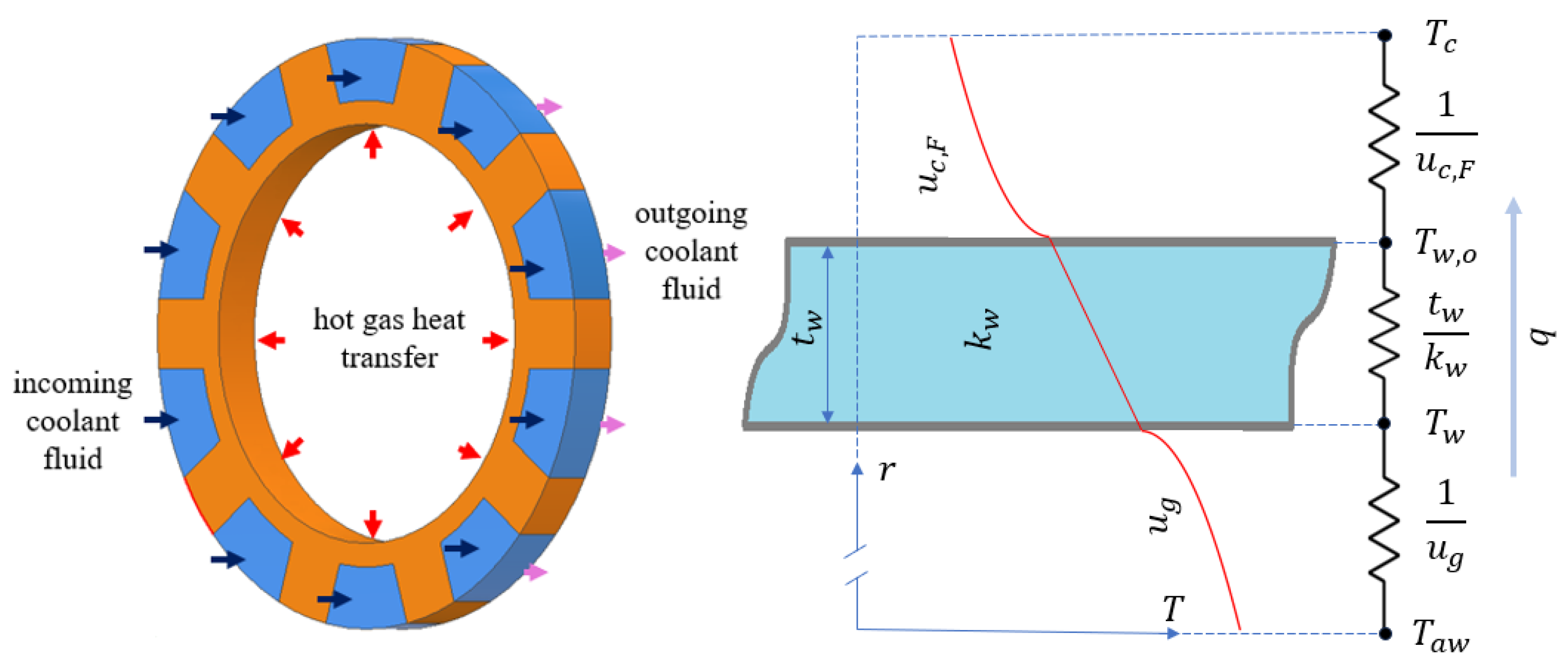
Between the hot gas and the coolant, there are three thermal resistances: the hot gas film, the thrust chamber wall, and the coolant film, as depicted in Figure 2. In a high Mach number hot gas flow, instead of the free stream gas temperature, it is assumed that the adiabatic wall temperature, , is the driving temperature for convection, which is given as follows [29]:
where Pr is the Prandtl number at the particular discretized point.
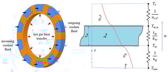
Figure 2.
Display of the thermal equilibrium at a section of thrust chamber and the thermal resistances.
On the other hand, the convection coefficient of the combustion gas film is found by Bartz correlation [30]:
where t, , and g subscripts denote the throat, combustion chamber, and hot gas, respectively. In this equation, is the characteristic velocity, is the throat diameter, is the specific heat of the gas, and is the dynamic viscosity of the gas. Here, the correction factor, , is given by the following expression:
where denotes the wall temperature on the hot gas side. Therefore, the heat flux, q, from the hot combustion gases to the inner wall of the thrust chamber would be the following:
This heat flux would be conducted radially outwards through the engine wall, as shown in Figure 2. Since the engine wall thickness is generally too small compared to the diameter, the radial heat transfer could be approximated as planar. Therefore, the heat flux given by Equation (6) also equals the following:
where is the wall thermal conductivity, is the wall thickness, and is the wall temperature at the base of the cooling channel.
The coolant flow is assumed to be turbulent and fully developed. The convection coefficient for the coolant flow, , is found using the Dittus–Boelter correlation given by [31]:
where Re is the Reynolds number of the coolant flow inside the cooling channel, is the thermal conductivity of the coolant, and the hydraulic diameter is given by , where is the area, and is the perimeter of the cooling channel. In ODREC, the cooling channel cross section is assumed to be a rectangle as depicted in Figure 1.
As shown in the cross-section view of a rocket engine illustrated in Figure 1, the walls separating the cooling channels constitute an extended surface, or a fin, with an adiabatic tip. Therefore, the fin effect should be accounted for in the evaluation of the convection coefficient by calculating the fin efficiency, :
where is the fin width, and is the cooling channel depth. Due to the rotational symmetry, only a half channel is sufficient in calculating the overall fin effect of the extended surface by assuming the half channel as insulated from the dashed lines in Figure 1. The convection coefficient that is corrected for the fin effect, , is then given as follows:
where w is the channel width. Hence, the heat flux from the outer wall of the engine to the coolant would be
The radiative heat transfer is neglected due to the contribution generally being less than 10% [32]. Using a thermal resistance approach would decrease the number of unknowns in the calculation of the heat flux, which is expressed in Equation (6), (7), and (11). Combining the effects of the thermal resistances due to the convection on the hot gas side, the conduction across the wall and the convection on the coolant flow side, which are portrayed in Figure 2, the heat flux is found as follows:
3. Description of the Tool
ODREC, developed using object-oriented programming in the MATLAB environment, is designed as a complete tool for preliminary engine design and regenerative cooling analysis.
3.1. Input/Output Structure
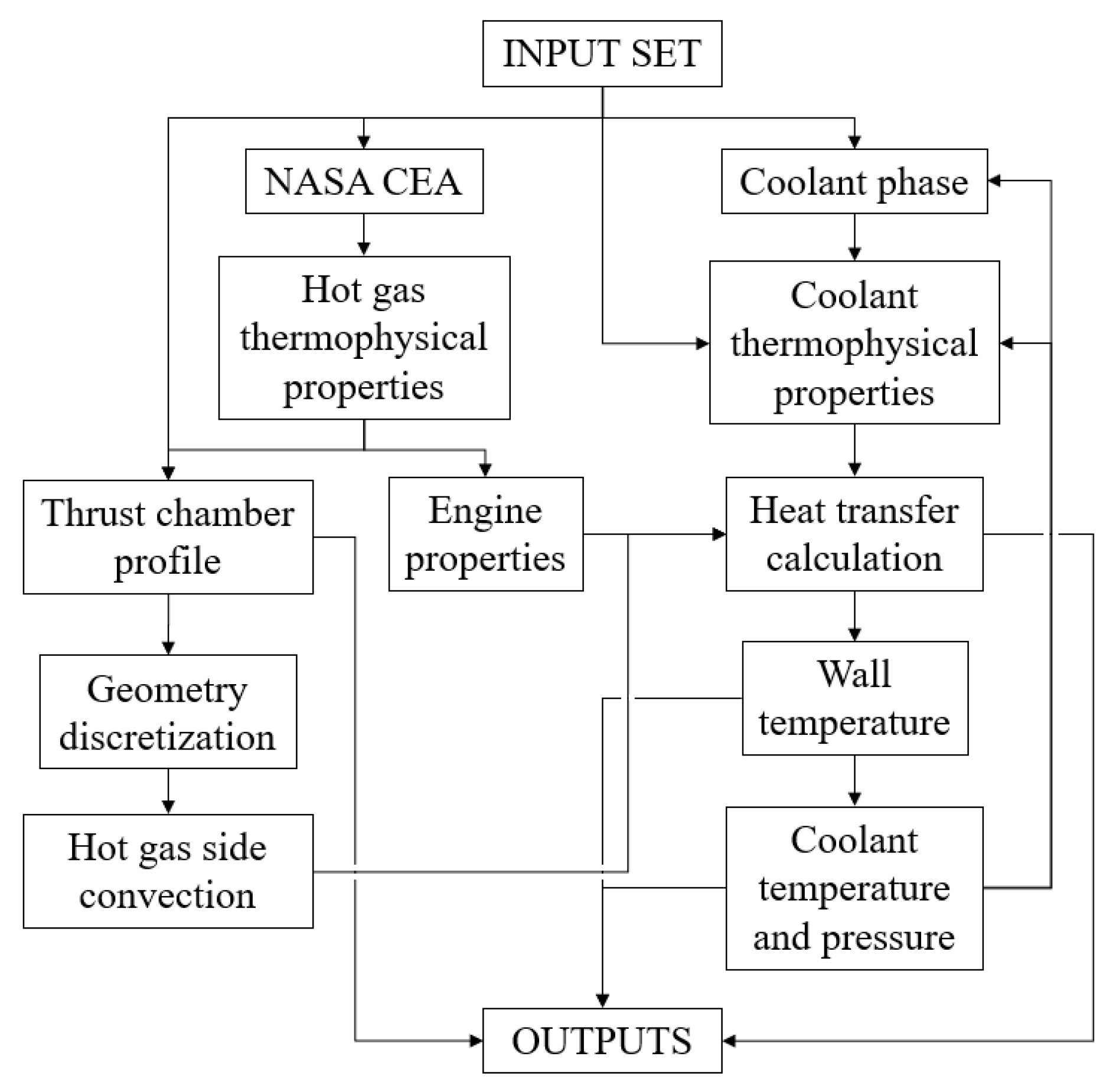
ODREC accepts a set of input parameters, as shown in the flowchart given in Figure 3. These parameters include the name of the oxidizer and the fuel, the thrust, the oxidizer-to-fuel mixture ratio, the combustion chamber pressure, the ambient pressure, the fuel and oxidizer temperatures entering the combustion chamber, the engine wall roughness, the thermal conductivity, whether the fuel or the oxidizer is the coolant, the coolant inlet temperature and pressure, the number, width, and depth of the cooling channels, the wall thickness at channel base, the characteristic length of the combustion chamber, the nozzle inflection and exit angles, and the number of discretization at each thrust chamber part. In addition, coolant thermophysical properties for liquid, saturated, and vapor phases should be given as inputs, besides the pressure values for which vapor property tables are provided. The required coolant thermophysical properties are dynamic viscosity, thermal conductivity, constant pressure specific heat, and density. Properties of the coolant at a certain pressure and temperature are obtained by interpolation, which is explained in Section 3.3. Thermophysical properties could be obtained from the NIST database [33].

Figure 3.
Flowchart of operations in ODREC.
In order to avoid the challenging 3-D combustion analyses in rocket engines, a 1-D analysis conducted by the NASA CEA program [34] is used. To improve the robustness of the tool, an open-source MATLAB implementation of the program developed in [35] is integrated into the tool. Therefore, the notation in defining the name and the temperatures of the propellants is the same as that on the CEA website [34]. In addition, another MATLAB package that allows using dimensional variables is also required to use the tool [36]. The properties of the combustion products at a certain temperature are obtained through interpolation or extrapolation using the values at the combustion chamber and at the nozzle throat extracted from the MATLAB implementation of CEA.
A built-in function in ODREC generates a thrust chamber profile based on a bell-shaped nozzle [37,38] and a cylindrical combustion chamber. However, if desired, a user may provide the thrust chamber profile externally. Also, channel depth and width may be given as variables or constants along the thrust chamber. The program outputs the specific impulse, the thrust coefficient, the characteristic velocity, the gas Mach number, the thrust chamber profile, the wall temperature, the wall heat flux, the mass flow rate, the vapor fraction, and the pressure and temperature of the coolant.
3.2. Algorithm of the Coolant State
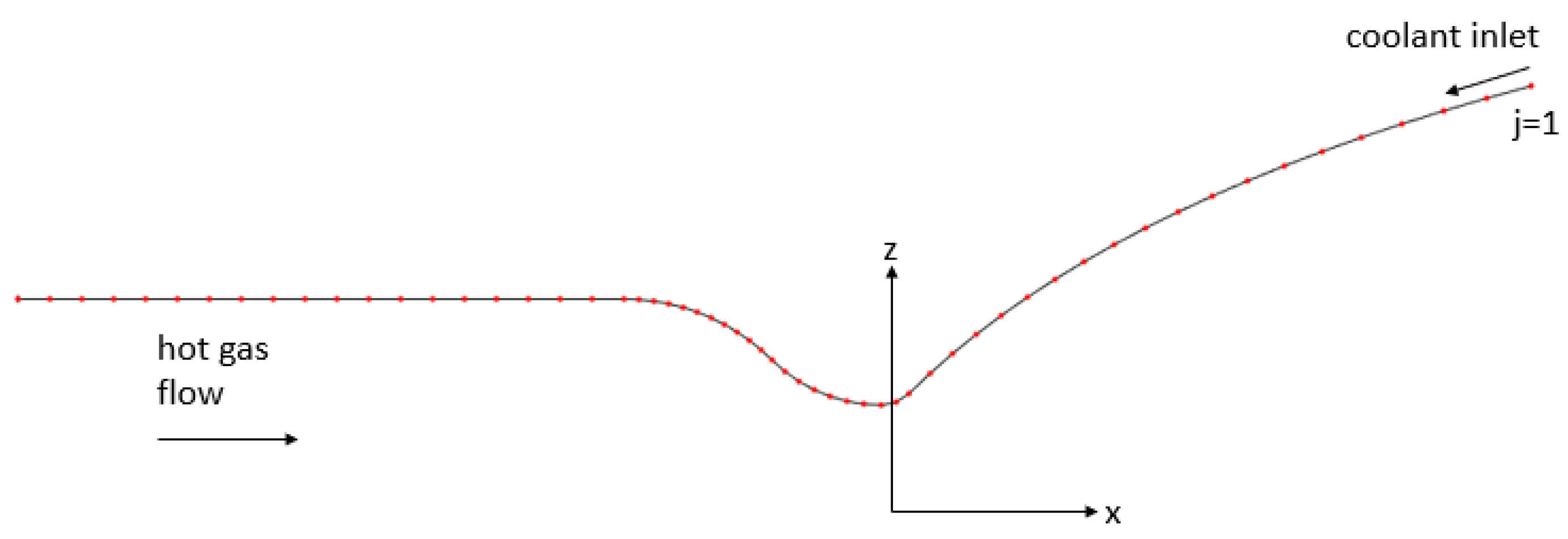
The thrust chamber is discretized into a certain number of sections as shown in Figure 4. The coolant is assumed to be entering the channels at the nozzle exit; therefore, the nozzle exit is the first section. In the solution algorithm, channel volumes in each discretized section, depicted in Figure 2, is analyzed as an independent control volume. Energy flows into each control volume by means of the heat transferred from the hot gas and through the enthalpy of the entering coolant fluid, and flows out of the control volume through the enthalpy of the exiting coolant fluid. Therefore, in a steady state, the energy balance in a section j gives the following approximation for the coolant temperature .
where N is the number of channels, L is the length of the particular section, and the superscript j denotes the section index. At each section, the heat flux is calculated by Equation (12) using the temperature of the coolant calculated at the previous section by Equation (13). Furthermore, the inner wall temperature is calculated as follows:
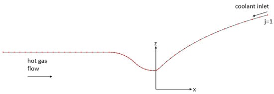
Figure 4.
Discretized sections on the thrust chamber contour.
Here, it should be noted that there is an implicit relation between the gas convection coefficient and the wall temperature, since Equation (5) includes the wall temperature. Therefore, at each section, the wall temperature is iterated until a convergence criterion, namely that the temperature difference between the respective iterations should be under 0.1 K, is satisfied.
Furthermore, the coolant pressure in each section can be found as follows:
where is the density, and v is the velocity. The first term inside the parenthesis relates to the minor pressure loss, and the second term relates to the major pressure loss. The minor loss coefficient is determined by the expansion and contraction of the diameter using the formulae given in [9], and the friction coefficient f is found by the Haaland equation given as follows [28]:
where is the roughness of the channel wall.
3.3. Algorithm of the Coolant Phase and Thermophysical Properties
In ODREC, the phase of the coolant at a section is determined using the so-called interpolated temperature, which is found as follows:
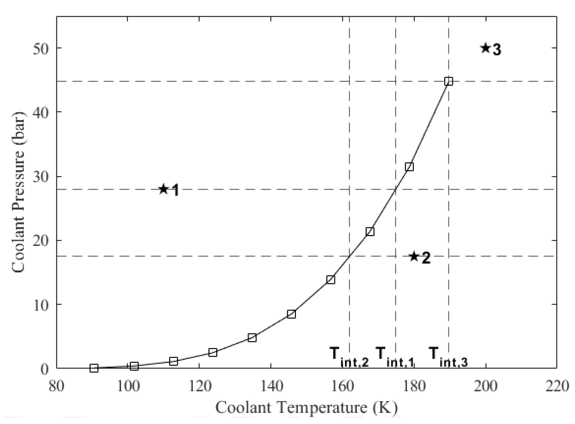
where and are the temperature and the pressure values on the saturation line, respectively, which are read from the saturation thermophysical property table. Subscripts u and l denote upper and lower, respectively, indicating that the coolant pressure at the particular section is in between these values. If the coolant pressure at the particular section is greater than the highest pressure value on the saturation line, then the interpolated temperature becomes the highest temperature value on the saturation line. The interpolation process is visualized in Figure 5. In this figure, there are three example states labeled as 1, 2, and 3, for which the interpolated temperatures are projected onto the horizontal axis. After the interpolated temperature is obtained, the phase of the coolant is found as follows: (i) if the coolant temperature is lower than the interpolated temperature, the coolant is in the liquid phase; (ii) if the coolant temperature is equal to the interpolated temperature, it is in the saturated phase; (iii) if the coolant temperature is higher than the interpolated temperature, it may be in the vapor or supercritical phase. In Figure 5, State 1 is liquid, State 2 is vapor, and State 3 is supercritical fluid. If the coolant temperature turns out to be greater than the interpolated temperature at a section but it was lower than the interpolated temperature at the previous section, then the coolant has started changing phase. Therefore, its actual temperature equals the interpolated temperature evaluated at its pressure value at the section it occupies until the phase change is completed.
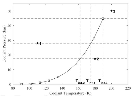
Figure 5.
Example cases for the determination of the coolant’s phase. *1: liquid, *2: vapor, *3: supercritical.
Thermophysical properties of the coolant along the channels are determined by interpolations, with the values in the tables provided by the user, using the pressure and temperature values of the coolant. In the liquid phase, the thermophysical property table is provided for a range of temperatures without using any pressure value since the thermophysical properties of liquids are almost invariant of pressure due to the negligible compressibility. On the other hand, the table for the saturation phase should include both the pressure and the temperature values on the saturation curve besides the corresponding saturated liquid and saturated vapor thermophysical properties. The provided properties should also include the specific enthalpy in this phase. At the moment that the phase change begins, the specific enthalpy of the coolant is equal to the saturated liquid’s specific enthalpy. As the phase changing coolant flows through the channels, its pressure drops at the same time its specific enthalpy rises due to the absorbed heat. The coolant state will stay on the saturation line until the phase change is completed; therefore, the coolant temperature will drop in the course of the phase change even if the enthalpy rises. In the course of this phase, specific enthalpy, h, of the coolant is updated as follows:
Vapor fraction, , on the other hand, is calculated at each section as follows:
where and are saturated liquid and saturated vapor enthalpies, respectively, which are interpolated using the coolant state parameters. In the vapor phase, on the other hand, a three-dimensional array composed of a number of tables should be provided, each of which includes isobaric values of density, viscosity, specific heat, and thermal conductivity for a range of temperatures at a particular pressure value. It should be noted that the pressure values at which the properties are provided are chosen by the user. To obtain the thermophysical properties of the coolant vapor at a section, a two-step interpolation is made using the state variables T and P. In the first step, an isobaric property curve is interpolated using the coolant pressure within the given tables, and the property is then interpolated in this specific curve using the coolant temperature. The methodology that is discussed in this subsection enables the program to evaluate the change of phase fast and accurately.
4. Results and Discussion
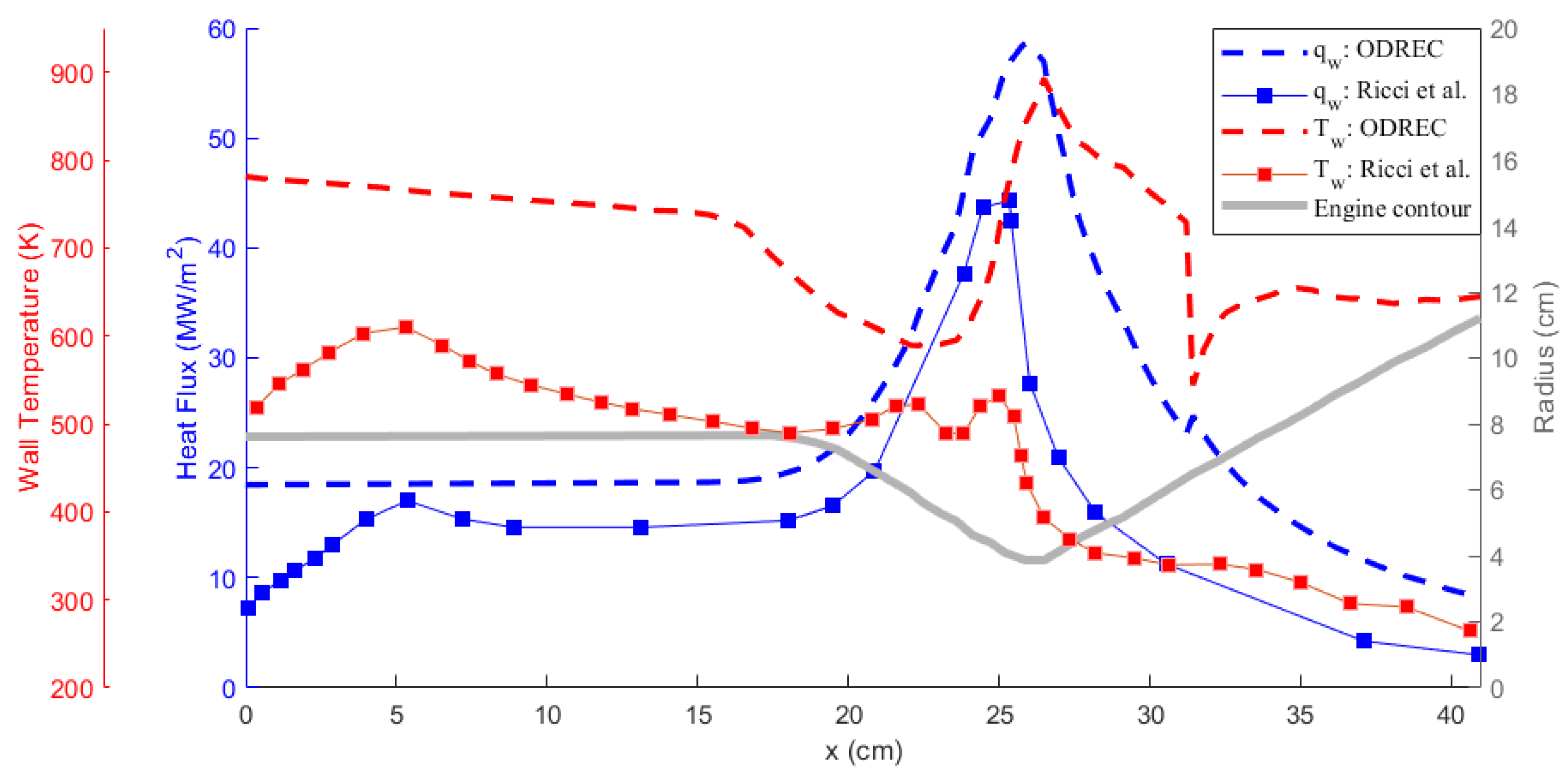
In order to test ODREC, the results of the study carried out by Ricci et al. [39] were reproduced. In that study, the authors analyzed the regenerative cooling of a 30 kN thrust class LOX/LCH4 engine demonstrator that operates at an oxidizer-to-fuel ratio of 3.4 and a combustion chamber pressure of 55 bar [40]. They adopted a numerical approach that had been experimentally validated in a breadboard campaign [41]. A 3-D CFD model was created for the conjugate heat transfer analysis of the channel/coolant side. Additionally, an input heat flux obtained through reactive CFD analysis was defined on the hot gas side of the engine wall. The cooling channel dimensions, thrust chamber profile, and calculated results were obtained by digitizing the plots in the reference study [42]. The same case was then analyzed using ODREC.
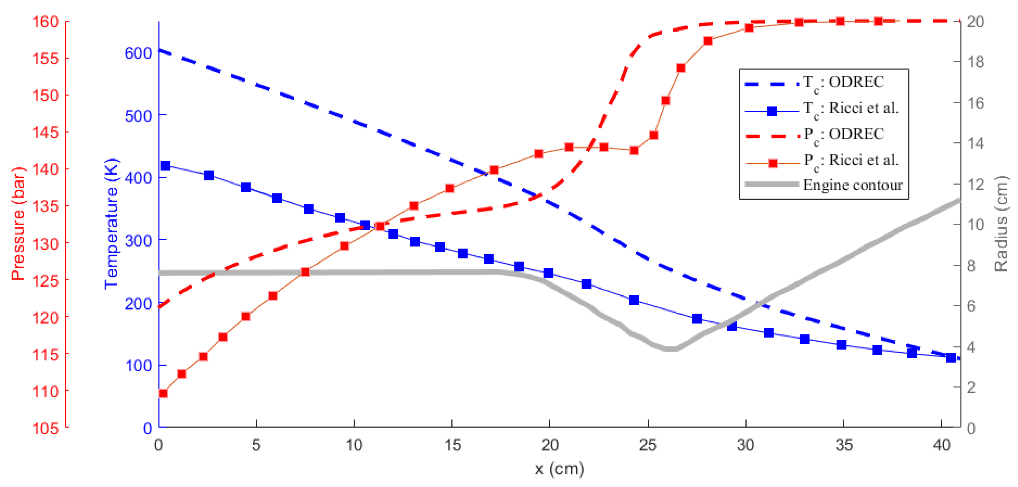
Comparison of the results obtained using ODREC and the results of the reference study are shown in Figure 6 and Figure 7 for the wall temperature and the wall heat flux and for the coolant temperature and pressure, respectively. As the results in Figure 6 suggest, the wall heat flux was somewhat over-predicted by ODREC compared to the reference study, but the overall trend was captured. Wall temperature, however, was severely over-predicted, despite displaying similar trends. On the other hand, results in Figure 7 show that the coolant pressure drop calculation was fairly accurate compared to the reference study. The coolant temperature was over-predicted as a result of the higher estimated wall temperatures as well.
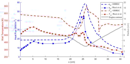
Figure 6.
Comparison of the hot gas side wall temperature and heat flux results with the reference study [39].
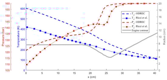
Figure 7.
Comparison of the temperature and the pressure of the methane coolant results with the reference study [39].
It can be concluded that such a simple 1-D approach is not sufficient to perfectly reproduce the results of an experimentally validated, intensive numerical method. This mainly results from the use of the approximations presented by the Bartz correlation, Haaland equation, and Dittus–Boelter correlation as discussed in [43]. Particularly for LOX/LCH4 engines, the Bartz correlation is reported to over-predict [44]. This shows that the propellant combination also plays a role in increasing the accuracy of the correlations [2], where in ODREC the most general correlations are used. The software being open source provides the user the freedom to modify the particular correlations. Additionally, 1-D analyses usually over-predict the temperature as also encountered in [13]. However, the authors of that study also rightfully state that the aim of a 1-D thermal analysis is to provide a rapid estimation of the trends rather than very accurate estimations. Similarly, the results produced by the current tool provide insight about the thermal behavior within a certain margin. Furthermore, the phase change phenomenon is easily integrated without a high computational power demand. Therefore, this tool could be utilized to accelerate the early design phase by conducting parametric studies to evaluate the effects of geometrical parameters on thermal behavior, comparing different coolants and further examining the optimum design parameters.
A Regenerative Cooling Comparison of LOX/LCH4 and LOX/LC3H8 Engines
Regenerative cooling analyses of two small-scale rocket engines, a LOX/LCH4 engine with an OF ratio equal to 4 and a LOX/LC3H8 engine with an OF ratio equal to 3.9, both operating at a combustion chamber pressure of 26 bar and delivering a thrust of 15 kN, were carried out using ODREC. Relevant input parameters that are not explained in the text are given in Table 1. Combustion chamber entry temperature inputs for liquid fuel and liquid oxidizer are given as dictated by the CEA program as mentioned in Section 3.1. In this context, the LOX, LCH4, and LC3H8 combustion chamber entry temperatures were set to 90.17 K, 111.64 K, and 231.076 K, respectively. The thermophysical properties of oxygen, methane, and propane for the liquid, saturated, and vapor phases were acquired from the NIST database. The inlet pressures and inlet temperatures of all coolants were set to 37 bar and 105 K, respectively. Here, it should be noted that both engines have the same thrust chamber profile, which is as depicted in the following figures.

Table 1.
Input values used in the analysis.
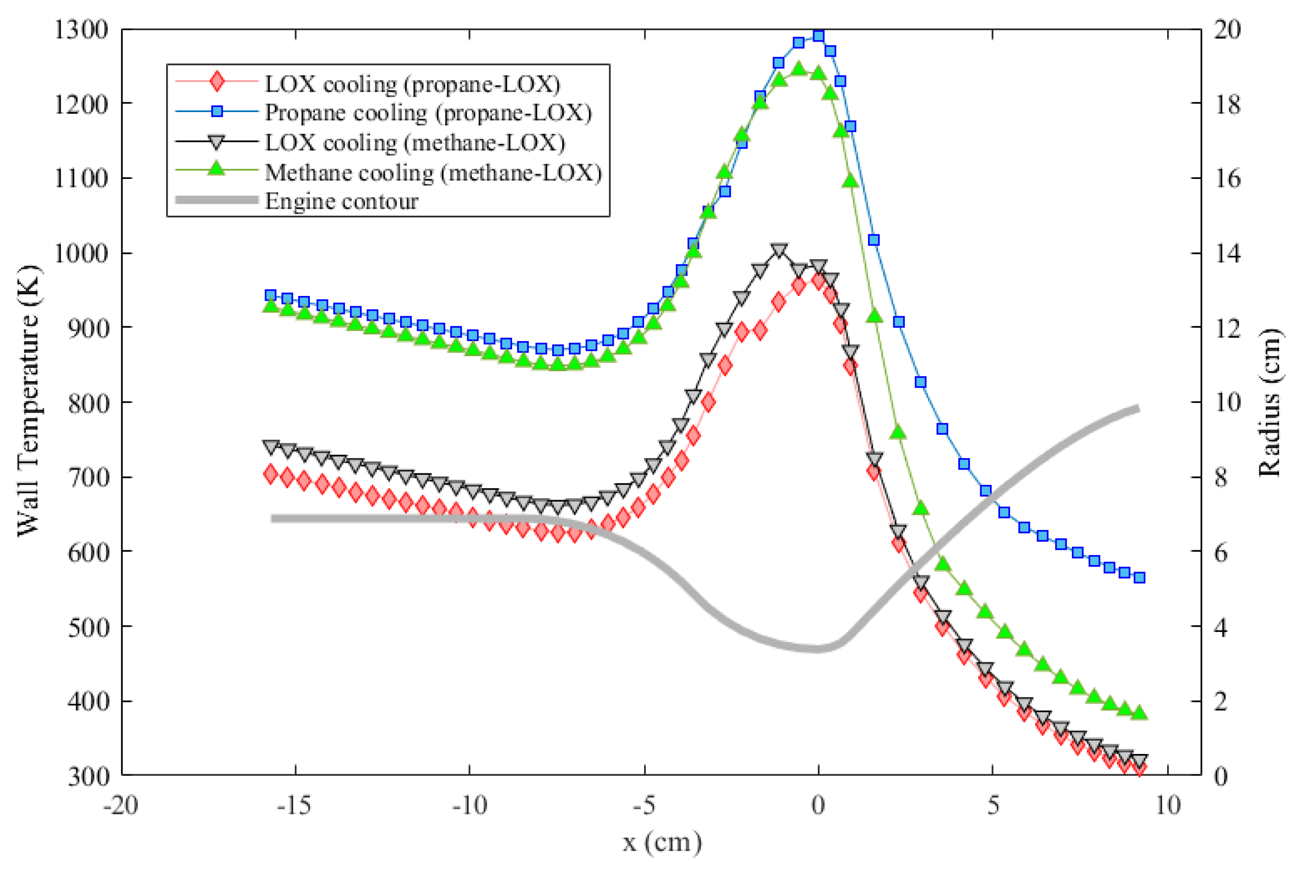
The performances of both fuel and oxidizer as the coolant for both engines under the effect of coolant phase change were compared. Results of the gas side wall temperature are given in Figure 8. As the results suggest, oxygen cooling, which results in a maximum wall temperature around 980 K, provides the best cooling performance for both engines under the specific conditions considered. Although methane cooling results in a lower wall temperature compared to propane cooling, cooling with neither propane nor methane can enable a maximum wall temperature under 1000 K according to the analyses. A remark here is that the maximum temperature near the throat is probably over-estimated, and the minimum temperature towards the nozzle exit is probably under-estimated. One reason for this is the fact that the axial conduction in the engine wall is neglected.
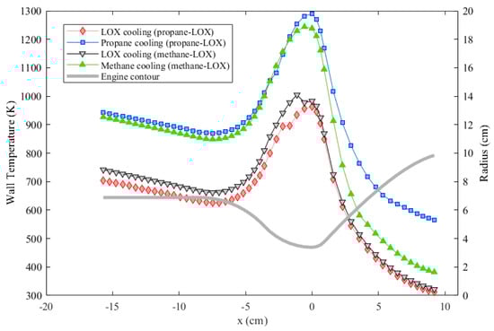
Figure 8.
Wall temperature comparison of the two engines each assumed to be cooled either with the oxidizer or with the fuel.
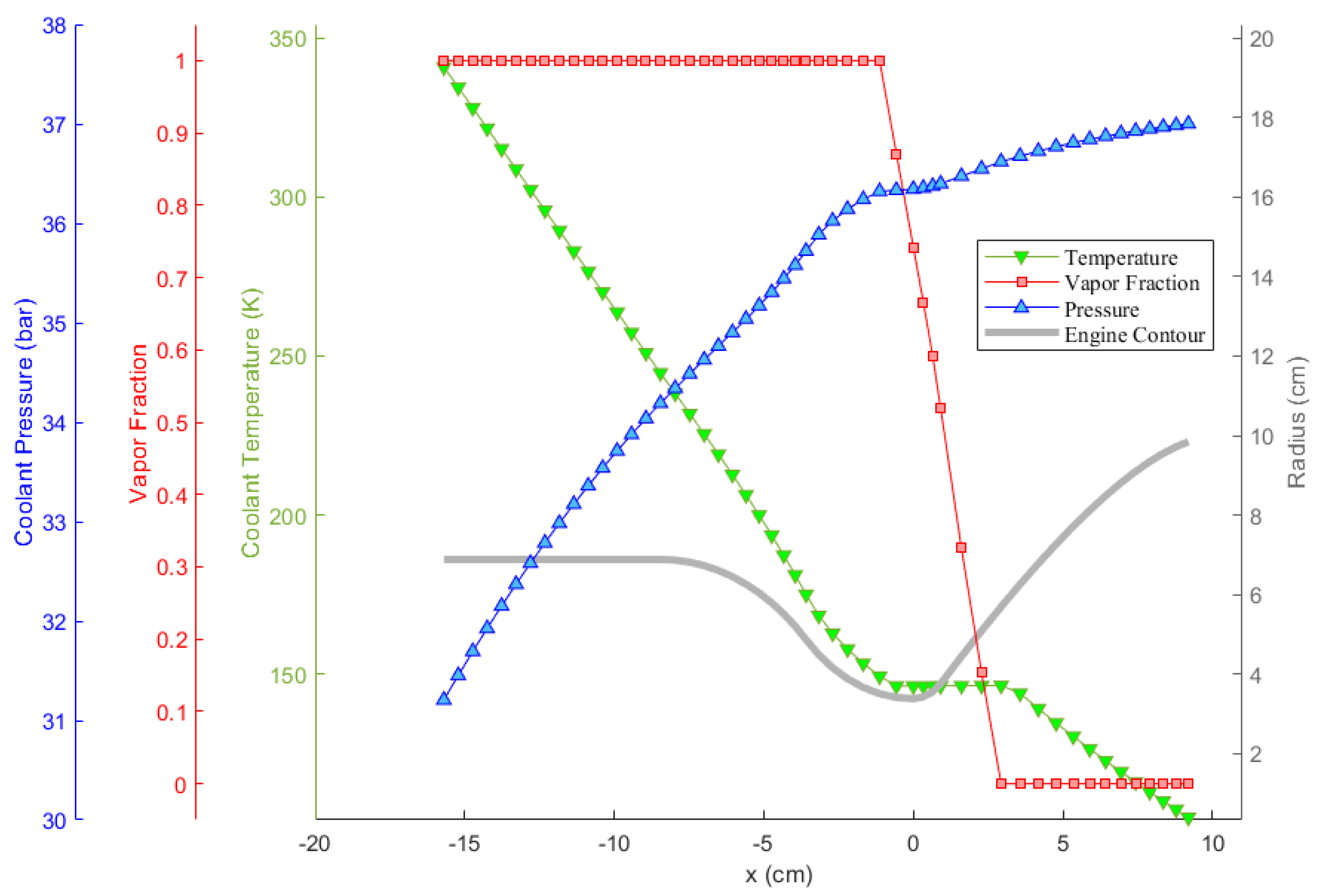
Oxygen coolant in the LOX/LC3H8 engine is examined closer in Figure 9 as an example. In the figure, the pressure, temperature, and vapor fraction of the coolant along the cooling channels throughout the thrust chamber are presented. It can be observed that the coolant experiences phase change. As can be seen, the coolant temperature does not increase in the course of phase change, as would be expected. In addition, near the phase change, or saturation, region, the rate of change of temperature is lower, indicating an increase in coolant heat capacity. The coolant pressure, on the other hand, drops steadily in the diverging nozzle section due to the moderate minor loss coefficient, , which stems from the radius gradient. After the coolant completely changes its phase into vapor, on the other hand, its pressure drops more rapidly, independently of the radius gradient. This stems from the fact that the vapor density is significantly lower, resulting in the domination of major pressure loss due to the increasing velocity, as resulted from Equation (15).
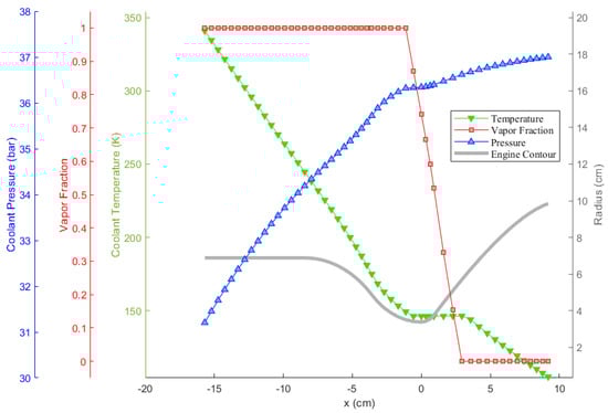
Figure 9.
Change of the properties of the oxygen coolant throughout the LOX/LC3H8 engine cooling channels.
The phase change phenomenon is inspected in Figure 10 as well. In the figure, the evolution of coolant states inside the cooling channels is given on a P-T diagram. Thin lines represent the saturation lines of propane, methane, and oxygen. The initial state of the coolants is at the upper left corner. Up to the saturation line, coolant temperatures rise and coolant pressures drop as expected. When a coolant state encounters its corresponding saturation line, on the other hand, it follows the saturation line until the vapor fraction becomes unity. Meanwhile, the coolant pressure keeps dropping due to major and minor losses. This means that, since the coolant state stays on the saturation line, the coolant temperature drops very slightly in the course of phase change even if the coolant enthalpy increases, as mentioned earlier in Section 3.3. The temperature drop of the oxygen coolant is shown in a zoom-in view in Figure 10.
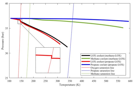
Figure 10.
Pressure versus temperature evolution of the considered coolants as they change phase along the thrust chamber cooling channels.
Figure 10 also shows that, for methane and propane, temperature rises are much greater and the pressure drops are much smaller compared to those of oxygen. These facts are also represented in Table 2. The ultimate reason for these changes is that the oxidizer mass flow rate is greater than the fuel mass flow rate for both cases, which is also presented in Table 2. Even if oxygen has the lowest specific heat out of the three propellants as shown in Figure 11, heat capacity, which is the mass flow rate multiplied by the specific heat, is the highest in the oxygen flow for both engines. Figure 12 shows the heat capacity of all coolants along the cooling channels throughout the thrust chamber for both engines cooled with both propellants. The oxygen heat capacity has the highest values for both cases along the entire region. A higher heat capacity enables the coolant to store thermal energy with a lower temperature increase at the outlet, as shown in Table 2, which, in turn, results in a lower wall temperature overall. Figure 12 also indicates that, in the phase change region, the heat capacities of all coolants rise sharply, due to the contribution of latent heat to heat capacity. The spiky behavior of the specific heats is exhibited in Figure 11. The figure presents the change of the specific heats in the temperature range from 100 to 600 K at a constant pressure of 35 bar, which is roughly the working pressure in this analysis. The data are obtained from the NIST database at 20 K intervals, which is roughly the data interval used in the analysis. The propellants change their phase at significantly different temperatures, where the respective specific heats spike at corresponding phase change temperatures.
Table 2.
Resulting coolant parameters.
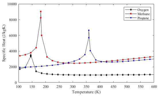
Figure 11.
Specific heat values of oxygen, methane, and propane at the constant pressure of 35 bar.
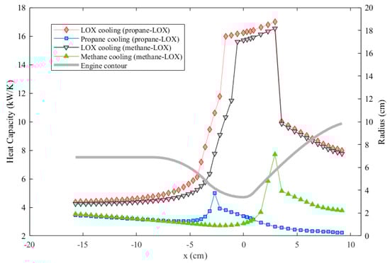
Figure 12.
Comparison of the heat capacities of different coolants throughout the cooling channels.
Another significant factor determining the engine wall temperatures is how efficiently heat flows from the cooling channel wall to coolant, i.e., the heat transfer coefficient in the cooling channels. Coolant convective heat transfer coefficients corrected for the fin effect for all coolants are presented in Figure 13. As the results suggest, oxygen cooling provides the highest values for both cases. The primary reason for this is the higher oxidizer mass flow rate as well. According to Equation (8), the heat transfer coefficient is proportional to the mass flow rate through the Reynolds number. A higher heat transfer coefficient results in a lower wall temperature overall, as in the case of oxygen cooling.

Figure 13.
Comparison of the fin heat transfer coefficients of different coolants throughout the cooling channels.
5. Conclusions
This study presents the application of a 1-D analysis on the regenerative cooling of liquid propellant rocket engines. An analysis tool, ODREC (One-Dimensional Regenerative Cooling), was developed using object oriented programming in MATLAB (MathWorks, Natick, MA, USA). ODREC carries out a combustion analysis based on a MATLAB implementation of the NASA CEA program. Gas side heat transfer was approximated using isentropic and adiabatic flow assumptions, along with appropriate heat transfer correlations. On the coolant side, heat transfer correlations are utilized considering the fin effect, and the thermodynamics of the coolant was included. A thermal resistance approach was used to calculate the radial heat transfer, and a 1-D hydraulic analysis was conducted to calculate the pressure of the coolant. Results of a study from the literature are reproduced using ODREC. Though ODREC over-predicts the engine wall temperatures, it captures the overall trends in the reference study. One of the primary benefits of ODREC is that complex phenomena such as phase change can be resolved with ease, and a solution takes only a few seconds. Therefore, it is an excellent candidate for use in optimization studies. In addition, the analysis was carried out compactly without needing other software for combustion analysis and engine sizing. ODREC also provides the flexibility to externally assign the thrust chamber profile as well as the ability to generate it within the program.
In this study, the regenerative cooling of two small-scale rocket engines, a LOX/LCH4 engine and a LOX/LC3H8 engine, was investigated using ODREC. All coolants were designated to experience phase change. Results show that oxygen cooling provides the lower wall temperature overall for both cases. This stems from the fact that both the heat capacity and heat transfer coefficient of the oxidizer flow are superior for both cases, since the oxidizer mass flow rate is greater than the fuel mass flow rate. In a real engineering application, however, the oxidation of the channel surface due to the coolant oxidizer could be a concern. The thermophysical properties of methane were superior to those of propane in terms of heat transfer, but the temperatures of both propane-cooled and methane-cooled engines still exceeded 1000 K. This might require the additional use of film cooling for the specific engines considered. Furthermore, the pressure drop of the methane and propane coolants was much smaller compared to oxygen. Modifying the channel parameters might have enabled improved cooling at the expense of an increasing pressure drop. However, the channel width was set to 1 mm, and the number of channels was kept constant for both engines in the course of the analysis. Channel parameter optimization utilizing ODREC could be a topic of future study.
Author Contributions
Conceptualization, Y.M.K. and M.C.; methodology, Y.M.K.; formal analysis, Y.M.K.; writing—original draft preparation, M.C. and Y.M.K.; writing—review and editing, Y.M.K. and M.C.; supervision, M.C.; funding acquisition, M.C. All authors have read and agreed to the published version of the manuscript.
Funding
This research is funded by the Turkish Scientific and Technological Research Council (TUBITAK) under project number 214M572 and the Department of Scientific Research of Bogazici University (BAP) under project 18224.
Institutional Review Board Statement
Not applicable.
Informed Consent Statement
Not applicable.
Data Availability Statement
The data presented in this study are available in article.
Conflicts of Interest
The authors declare no conflict of interest.
References
- Sutton, G.P.; Biblarz, O. Rocket Propulsion Elements; John Wiley & Sons: Hoboken, NJ, USA, 2016. [Google Scholar]
- Huzel, D.K. Modern Engineering for Design of Liquid-Propellant Rocket Engines; AIAA: Reston, VA, USA, 1992; Volume 147. [Google Scholar]
- Nikischenko, I.N.; Wright, R.D.; Marchan, R.A. Improving the Performance of LOX/Kerosene Upper Stage Rocket Engines. Propuls. Power Res. 2017, 6, 157–176. [Google Scholar] [CrossRef]
- Naraghi, M.H.N. RTE: A Computer Code for Rocket Thermal Evaluation. In Proceedings of the Sixth Annual Thermal and Fluids Analysis Workshop, NASA Lewis Research Center, Cleveland, OH, USA, 17–21 August 1995. [Google Scholar]
- Nickerson, G.R.; Dang, L.D.; Coats, D.E. Engineering and Programming Manual: Two-Dimensional Kinetic Reference Computer Program (TDK); Technical Report; NASA Technical Reports Server: Cleveland, OH, USA, 1985. [Google Scholar]
- Wadel, M.; Meyer, M. Validation of high aspect ratio cooling in a 89 kN (20,000 lbf) thrust combustion chamber. In Proceedings of the 32nd Joint Propulsion Conference, Lake Buena Vista, FL, USA, 1–3 July 1996. AIAA-96-2584. [Google Scholar]
- Naraghi, M.; Dunn, S.; Coats, D. A Model for Design and Analysis of Regeneratively Cooled Rocket Engines. In Proceedings of the 40th Joint Propulsion Conference, Fort Lauderdale, FL, USA, 11–14 July 2004. AIAA-2004-3852. [Google Scholar]
- Ulas, A.; Boysan, E. Numerical analysis of regenerative cooling in liquid propellant rocket engines. Aerosp. Sci. Technol. 2013, 24, 187–197. [Google Scholar] [CrossRef]
- Naraghi, M.H.; Foulon, M. A Simple Approach for Thermal Analysis of Regenerative Cooling of Rocket Engines. In Proceedings of the ASME International Mechanical Engineering Congress and Exposition, Boston, MA, USA, 31 October–6 November 2008; Volume 48715, pp. 531–538. [Google Scholar]
- Wang, T.S.; Luong, V. Hot-Gas-Side and Coolant-Side Heat Transfer in Liquid Rocket Engine Combustors. J. Thermophys. Heat Transf. 1994, 8, 524–530. [Google Scholar] [CrossRef]
- Cho, W.K.; Seol, W.S.; Son, M.; Seo, M.K.; Koo, J. Development of Preliminary Design Program for Combustor of Regenerative Cooled Liquid Rocket Engine. J. Therm. Sci. 2011, 20, 467–473. [Google Scholar] [CrossRef]
- Kim, S.K.; Joh, M.; Choi, H.S.; Park, T.S. Effective Modeling of Conjugate Heat Transfer and Hydraulics for the Regenerative Cooling Design of Kerosene Rocket Engines. Numer. Heat Transf. Part A Appl. 2014, 66, 863–883. [Google Scholar] [CrossRef]
- Zhu, S.; Wei, R.; Hu, C.; Li, C. Regenerative-Cooling Heat-Transfer Performance of Mg/CO2 Powder Rocket Engines for Mars Missions. Int. J. Aeronaut. Space Sci. 2023, 24, 1–8. [Google Scholar] [CrossRef]
- Haeseler, D.; Bombelli, V.; Vuillermoz, P.; Lo, R.; Marée, T.; Caramelli, F. Green Propellant Propulsion Concepts for Space Transportation and Technology Development Needs. In Proceedings of the 2nd International Conference on Green Propellants for Space Propulsion, Chia Laguna (Cagliari), Sardinia, Italy, 2–4 June 2004; Volume 557. [Google Scholar]
- Roncioni, P.; Cardillo, D.; Panelli, M.; Ricci, D.; Di Clemente, M.; Battista, F. CFD Modelling and Simulations of the HYPROB Regenerative LOX/CH4 Thrust Chamber. In Proceedings of the 5th European Conference for Aeronautics and Space Sciences (EUCASS), Munich, Germany, 1–5 July 2013. [Google Scholar]
- Arun, M.; Amith, R.R.; Jose, P.M. Numerical Analysis of Combustion and Film Cooling in LOX-Methane Rocket Engine. J. Phys. Conf. Ser. 2019, 1355, 012009. [Google Scholar] [CrossRef]
- Haemisch, J.; Suslov, D.; Waxenegger-Wilfing, G.; Dresia, K.; Oschwald, M. LUMEN—Design of the Regenerative Cooling System for an Expander Bleed Cycle Engine Using Methane. In Proceedings of the 7th International Space Propulsion Conference, Virtual Conference, 17–19 March 2021; p. 68. [Google Scholar]
- Concio, P.; Migliorino, M.T.; Bianchi, D.; Nasuti, F. Modeling of Wall Heat Flux in Oxygen-Methane Liquid Rocket Thrust Chambers. In Proceedings of the AIAA AVIATION Forum, Chicago, IL, USA, 27 June–1 July 2022. AIAA-2022-3275. [Google Scholar]
- Concio, P.; Tindaro Migliorino, M.; Bianchi, D.; Nasuti, F. Numerical Estimation of Nozzle Throat Heat Flux in Oxygen-Methane Rocket Engines. J. Propuls. Power 2023, 39, 71–83. [Google Scholar] [CrossRef]
- Pizzarelli, M.; Battista, F. Oxygen-Methane Rocket Thrust Chambers: Review of Heat Transfer Experimental Studies. Acta Astronaut. 2023, 209, 48–66. [Google Scholar] [CrossRef]
- Denies, L. Regenerative Cooling Analysis of Oxygen/Methane Rocket Engines. Master’s Thesis, Delft University of Technology, Delft, The Netherlands, 2015. [Google Scholar]
- Song, J.; Liang, T.; Li, Q.; Cheng, P.; Zhang, D.; Cui, P.; Sun, J. Study on the Heat Transfer Characteristics of Regenerative Cooling for LOX/LCH4 Variable Thrust Rocket Engine. Case Stud. Therm. Eng. 2021, 28, 101664. [Google Scholar] [CrossRef]
- Kennedy, H.T. Sky Rockets in Flight, Biofuels Delight! The bioLPG Story, Orbex’s Biofuel Powered Space Rocket and More. 2021. Available online: https://www.biofuelsdigest.com/bdigest/2021/10/24/sky-rockets-in-flight-biofuels-delight-the-biolpg-story-orbexs-biofuel-powered-space-rocket-and-more/ (accessed on 17 December 2023).
- Boyd, W.C. LOX/Hydrocarbon Propellants for Space Propulsion Systems; Technical Report 841529; SAE: Warrendale, PA, USA, 1984. [Google Scholar]
- Liang, K.; Yang, B.; Zhang, Z. Investigation of Heat Transfer and Coking Characteristics of Hydrocarbon Fuels. J. Propuls. Power 1998, 14, 789–796. [Google Scholar] [CrossRef]
- Schoenman, L. LOX/Propane and LOX/Ethanol Combustion Chamber Heat Transfer. J. Propuls. Power 1991, 7, 538–548. [Google Scholar] [CrossRef]
- GitHub Repository of Yigithanmehmetkose. 2023. Available online: https://github.com/yigithanmehmetkose/ODREC (accessed on 17 December 2023).
- Munson, B.R.; Okiishi, T.H.; Huebsch, W.W.; Rothmayer, A.P. Fluid Mechanics; Wiley Singapore: Singapore, 2013. [Google Scholar]
- Leontiev, A.; Popovich, S.; Strongin, M.; Vinogradov, Y. Adiabatic Wall Temperature and Heat Transfer Coefficient Influenced by Separated Supersonic Flow. In Proceedings of the EPJ Web of Conferences, Novosibirsk, Russia, 22–25 November 2016; Volume 159. [Google Scholar]
- Bartz, D.R. A Simple Equation for Rapid Estimation of Rocket Nozzle Convective Heat Transfer Coefficients. Jet Propuls. 1957, 27, 49–51. [Google Scholar]
- Bergman, T.L.; Lavine, A.S.; Incropera, F.P.; DeWitt, D.P. Introduction to Heat Transfer; John Wiley & Sons: Hoboken, NJ, USA, 2011. [Google Scholar]
- Kirchberger, C.U. Investigation on Heat Transfer in Small Hydrocarbon Rocket Combustion Chambers. Ph.D. Thesis, Technische Universität München, Munich, Germany, 2014. [Google Scholar]
- Lemmon, E.W.; Huber, M.L.; McLinden, M.O. NIST Standard Reference Database 23; Reference Fluid Thermodynamic and Transport Properties–REFPROP; NIST: Gaithersburg, MD, USA, 2002. [Google Scholar]
- Gordon, S.; McBride, B.J. Computer Program for Calculation of Complex Chemical Equilibrium Compositions and Applications. Part 1: Analysis; Technical report; NASA Technical Reports Server: Cleveland, OH, USA, 1994. [Google Scholar]
- GitHub Repository of PurdueH2Lab. 2014. Available online: https://github.com/PurdueH2Lab/MatlabCEA (accessed on 17 December 2023).
- GitHub Repository of Tgvoskuilen. 2014. Available online: https://github.com/tgvoskuilen/MatlabTools (accessed on 17 December 2023).
- Rao, G. Exhaust Nozzle Contour for Optimum Thrust. J. Jet Propuls. 1958, 28, 377–382. [Google Scholar] [CrossRef]
- GitHub Repository of ravi4ram. 2020. Available online: https://github.com/ravi4ram/Bell-Nozzle (accessed on 17 December 2023).
- Ricci, D.; Battista, F.; Fragiacomo, M. Transcritical Behavior of Methane in the Cooling Jacket of a Liquid-Oxygen/Liquid-Methane Rocket Engine Demonstrator. Energies 2022, 15, 4190. [Google Scholar] [CrossRef]
- Ricci, D.; Battista, F.; Ferraiuolo, M.; Natale, P.; Fragiacomo, M. Development of a Liquid Rocket Ground Demonstrator Through Thermal Analyses. Heat Transf. Eng. 2019, 41, 1100–1116. [Google Scholar] [CrossRef]
- Ricci, D.; Natale, P.; Battista, F. Experimental and numerical investigation on the behaviour of methane in supercritical conditions. Appl. Therm. Eng. 2016, 107, 1334–1353. [Google Scholar] [CrossRef]
- Pizzarelli, M.; Betti, B.; Nasuti, F.; Ricci, D.; Roncioni, P.; Battista, F.; Salvatore, V. Cooling Channel Analysis of a LOX/LCH4 Rocket Engine Demonstrator. In Proceedings of the 50th Joint Propulsion Conference, Cleveland, OH, USA, 28–30 July 2014. AIAA-2014-4004. [Google Scholar]
- Gallo, G.; Kamps, L.; Hirai, S.; Carmicino, C.; Nagata, H. One-dimensional modelling of the nozzle cooling with cryogenic oxygen flowing through helical channels in a hybrid rocket. Acta Astronaut. 2023, 210, 176–196. [Google Scholar] [CrossRef]
- Tamura, H.; Ono, F.; Kumakawa, A.; Yatsuyanagi, N. LOX/methane Staged Combustion Rocket Combustor Investigation. In Proceedings of the 23rd Joint Propulsion Conference, San Diego, CA, USA, 29 June–2 July 1987. AIAA-87-1856. [Google Scholar]

Disclaimer/Publisher’s Note: The statements, opinions and data contained in all publications are solely those of the individual author(s) and contributor(s) and not of MDPI and/or the editor(s). MDPI and/or the editor(s) disclaim responsibility for any injury to people or property resulting from any ideas, methods, instructions or products referred to in the content. |
© 2023 by the authors. Licensee MDPI, Basel, Switzerland. This article is an open access article distributed under the terms and conditions of the Creative Commons Attribution (CC BY) license (https://creativecommons.org/licenses/by/4.0/).