
Design Optimization of Underground Mining Vehicles Based on Regenerative Braking Energy Recovery


Abstract
1. Introduction
2. Design of Regenerative Braking System for Underground Mining Vehicles
2.1. Selection of a Regenerative Braking System
2.2. Methods of Energy Storage for Mining Vehicles
2.3. Coupling Design of Regenerative Braking System for Underground Mining Vehicles
3. Analysis of Energy Consumption after Installing the Regenerative Braking Energy Recovery System
Analysis of Forces on the Underground Mining Vehicle
- (1)
- Rolling resistance:
- (2)
- Air resistance:
- (3)
- Uphill resistance:
- Calculation of Regenerative Braking Energy Recovery for Mining Vehicles
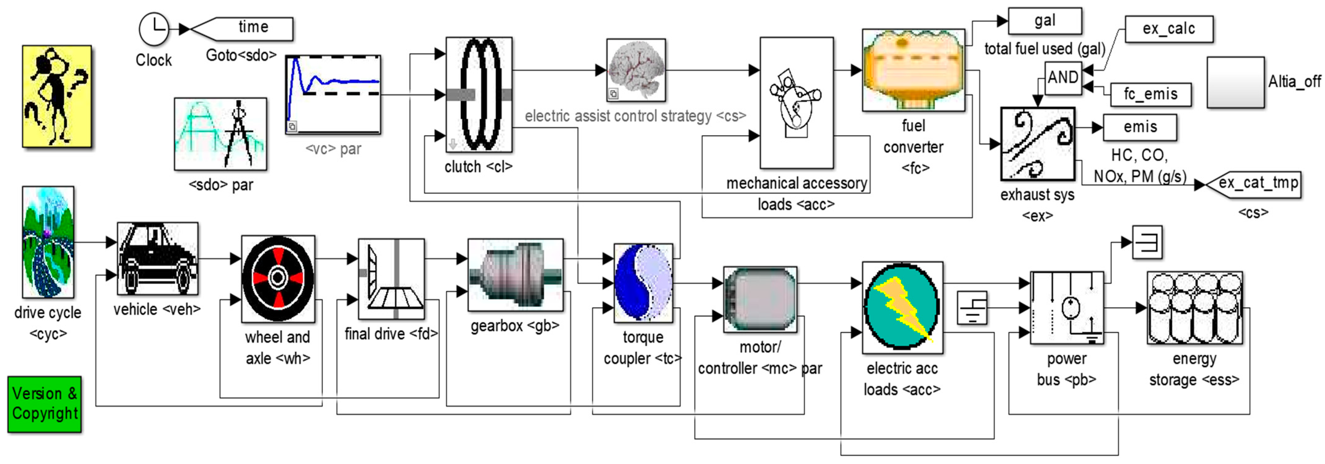
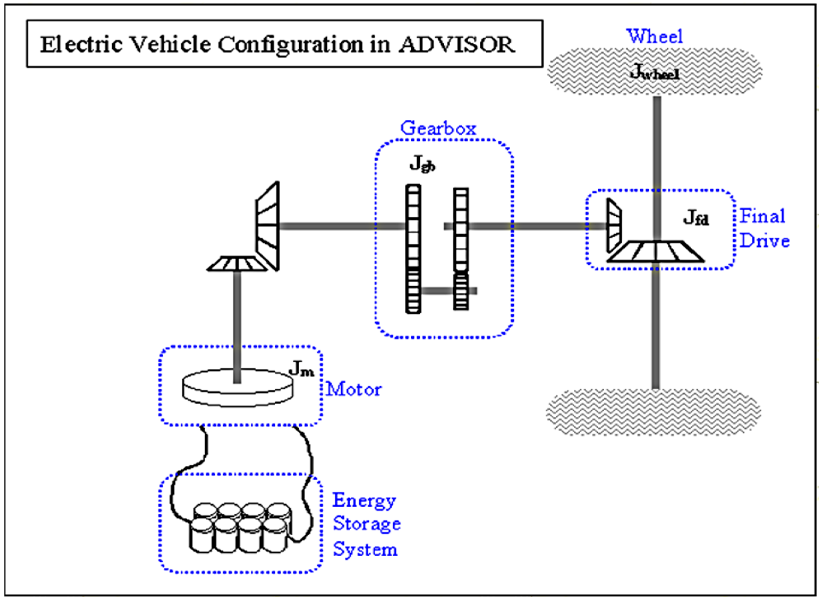
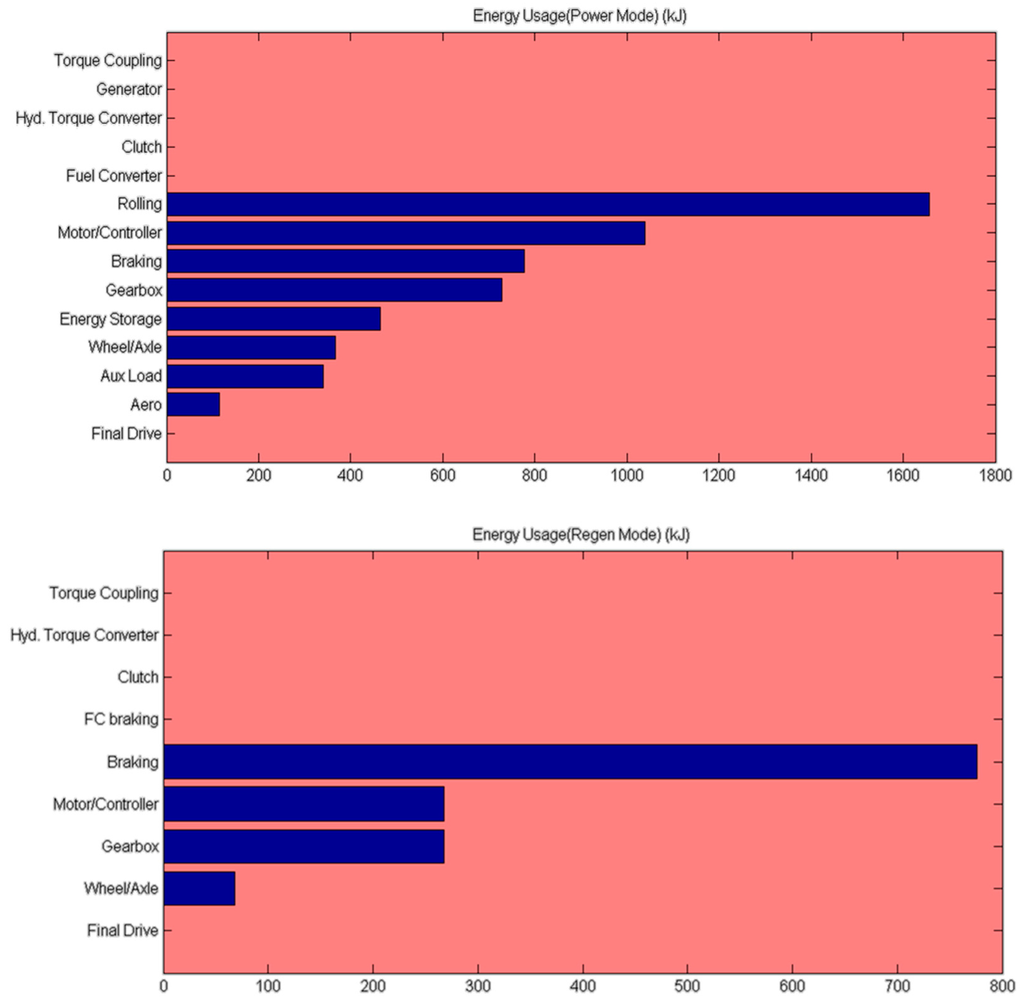
4. Simulation Modeling of Regenerative Braking Energy Recovery
5. Conclusions and Prospects
Author Contributions
Funding
Institutional Review Board Statement
Informed Consent Statement
Data Availability Statement
Conflicts of Interest
References
- Wo, X.; Li, G.; Sun, Y.; Li, J.; Yang, S.; Hao, H. The Changing Tendency and Association Analysis of Intelligent Coal Mines in China: A Policy Text Mining Study. Sustainability 2022, 14, 11650. [Google Scholar] [CrossRef]
- Liu, X.; Li, L.; Yang, Y. Development status of coal mining in China. J. S. Afr. Inst. Min. Metall. 2023, 123, 19–27. [Google Scholar] [CrossRef]
- Efremenkov, A.B.; Khoreshok, A.A.; Zhironkin, S.A.; Myaskov, A.V. Coal Mining Machinery Development As An Ecological Factor Of Progressive Technologies Implementation. In Proceedings of the Conference on Ecology and Safety in the Technosphere—Current Problems and Solutions, Yurga, Russia, 17–19 November 2016. [Google Scholar]
- Wu, X.; Li, H.; Wang, B.; Zhu, M. Review on Improvements to the Safety Level of Coal Mines by Applying Intelligent Coal Mining. Sustainability 2022, 14, 16400. [Google Scholar] [CrossRef]
- Zhao, S.; Chen, X.; Zhao, X. Analysis of Current Status and Development Direction of Coal Mining Technology in China. In Proceedings of the 4th International Conference on Energy Science and Applied Technology (ESAT), Chongqing, China, 29–30 December 2018. [Google Scholar]
- Hong, C. Vertical coupling vibration analysis of underground mine car-track based on computer simulation. Coal Technol. 2014, 33, 20–22. [Google Scholar] [CrossRef]
- He, H. Based on the analysis of the way to improve the maintenance efficiency of underground mine cars in coal mines. Inn. Mong. Coal Econ. 2020, 127+129. [Google Scholar] [CrossRef]
- Zuo, H. Design and application of automatic re-tracker for underground coal mine trucks. Small Medium-Sized Enterp. Manag. Technol. Low. 2014, 133–134. [Google Scholar]
- Wang, Y.; Chen, J.; Liu, J.; Liu, K.; Zhang, Y.; Wu, J.; Zeng, H.; Guan, Z.-L. Research and Implementation of Key Technology of Braking Energy Recovery System for Off-Highway Dump Truck. In Proceedings of the 43rd Annual Conference of the IEEE-Industrial-Electronics-Society (IECON), Beijing, China, 29 October–1 November 2017; pp. 3912–3917. [Google Scholar]
- Wang, Y.; Yang, W.; Yang, Y.; Zhang, W. Parameter matching of composite power supply for mining vehicle oriented by maximising braking energy recovery. Int. J. Heavy Veh. Syst. 2023, 30, 476–499. [Google Scholar] [CrossRef]
- Wang, Y.; Yang, W.; Zhang, W. Research on the braking energy reuse management strategy of hybrid electric mining trucks based on motor load rate. Proc. Inst. Mech. Eng. Part D-J. Automob. Eng. 2023. [Google Scholar] [CrossRef]
- Pielecha, I.; Cieslik, W.; Szalek, A. Energy recovery potential through regenerative braking for a hybrid electric vehicle in a urban conditions. In Proceedings of the 2nd International Conference on the Sustainable Energy and Environmental Development (SEED), Krakow, Poland, 14–17 November 2017. [Google Scholar]
- Zheng, L.; Shi, Z.; Luo, Y.; Kang, J. A Study of Energy Recovery System during Braking for Electric Vehicle. In Proceedings of the 6th International Conference on Applied Science, Engineering and Technology (ICASET), Qingdao, China, 29–30 May 2016; pp. 8–13. [Google Scholar]
- Xu, Z.-q. Research on Vehicle Braking Energy Recovery System and Energy Recovery Calculation. In Proceedings of the International Conference on Computational Science and Engineering (ICCSE), Qingdao, China, 20–21 July 2016; pp. 33–36. [Google Scholar]
- Han, T.; Zeng, B.; Tong, Y. Theoretical study on energy recovery rate of regenerative braking for hybrid mining trucks with different parameters. J. Energy Storage 2021, 42, 103127. [Google Scholar] [CrossRef]
- Xiong, Y.; Yu, Q.; Yan, S.; Liu, X. An Innovative Design of Decoupled Regenerative Braking System for Electric City Bus Based on Chinese Typical Urban Driving Cycle. Math. Probl. Eng. 2020, 2020, 8149383. [Google Scholar] [CrossRef]
- Ma, Z.; Sun, D. Energy Recovery Strategy Based on Ideal Braking Force Distribution for Regenerative Braking System of a Four-Wheel Drive Electric Vehicle. IEEE Access 2020, 8, 136234–136242. [Google Scholar] [CrossRef]
- Ji, F.; Pan, Y.; Zhou, Y.; Du, F.; Zhang, Q.; Li, G. Energy recovery based on pedal situation for regenerative braking system of electric vehicle. Veh. Syst. Dyn. 2020, 58, 144–173. [Google Scholar] [CrossRef]
- Geng, C.; Ning, D.; Guo, L.; Xue, Q.; Mei, S. Simulation Research on Regenerative Braking Control Strategy of Hybrid Electric Vehicle. Energies 2021, 14, 2202. [Google Scholar] [CrossRef]
- Duong, T.T.; Van Do, D.; Nguyen, T.T. Research on Braking Force Distribution in Regenerative Braking System Apply to Conventional Vehicle. In Proceedings of the 4th International Conference on Green Technology and Sustainable Development (GTSD), Ho Chi Minh City, Vietnam, 23–24 November 2018; pp. 48–52. [Google Scholar]
- Spichartz, P.; Sourkounis, C. Assessment of Recuperation Strategies for Electric Vehicles by Simulations and Measurements. In Proceedings of the International Symposium on Power Electronics Electrical Drives, Automation, and Motion (SPEEDAM), Anacapri, Italy, 22–24 June 2016; pp. 1226–1231. [Google Scholar]


| The Motor Brake Decoupled from the Hydraulic Brake | Adequate Recovery of Braking Energy | Applicable to Underground Mine Cars | |
|---|---|---|---|
| Iterative regenerative braking system | no | no | yes |
| Collaborative regenerative braking system | yes | yes | yes |
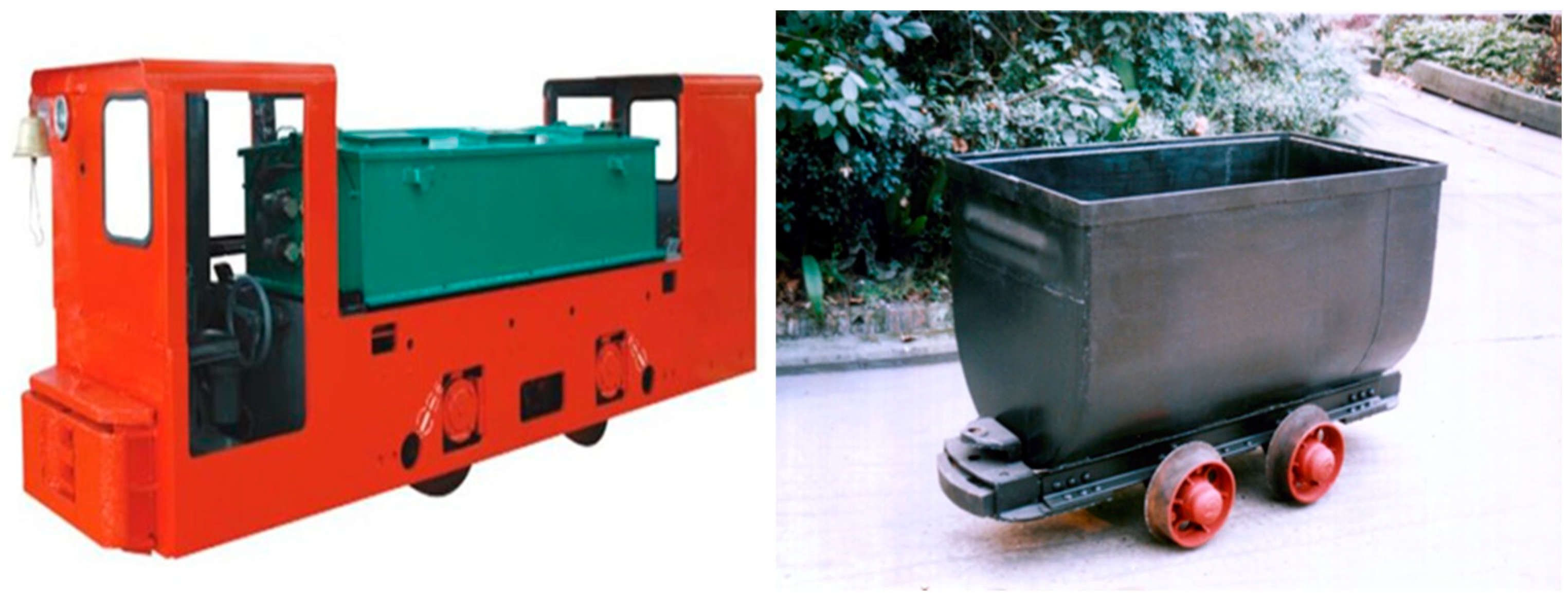
| Model Number | CTY5/6G(B) | |
|---|---|---|
| viscous | 5 t | |
| gauge | 600, 762 or 900 mm | |
| motive force | 7.06 kN | |
| More traction | 12.26 kN | |
| speed | 7 km/h | |
| Power supply unit | input voltage | 90 V |
| quantitative | 385 Ah | |
| Motor power × number of units | 7.5 kW × 2 | |
| sizes | Length (with bumper) | 3170 mm |
| widths | 920, 1082 or 1220 mm | |
| Height (rail to roof) | 1550 mm | |
| wheelbases | 850 mm | |
| diameter of the wheel | Φ520 mm | |
| Minimum Turning Radius | 6 m | |
| Speed control method | Resistance or chopper speed control | |
| braking method | mechanical brake | |
Disclaimer/Publisher’s Note: The statements, opinions and data contained in all publications are solely those of the individual author(s) and contributor(s) and not of MDPI and/or the editor(s). MDPI and/or the editor(s) disclaim responsibility for any injury to people or property resulting from any ideas, methods, instructions or products referred to in the content. |
© 2024 by the authors. Licensee MDPI, Basel, Switzerland. This article is an open access article distributed under the terms and conditions of the Creative Commons Attribution (CC BY) license (https://creativecommons.org/licenses/by/4.0/).
Share and Cite
Liu, P.; Hao, J.; Hu, H.; Luan, X.; Meng, B. Design Optimization of Underground Mining Vehicles Based on Regenerative Braking Energy Recovery. Appl. Sci. 2024, 14, 467. https://doi.org/10.3390/app14010467
Liu P, Hao J, Hu H, Luan X, Meng B. Design Optimization of Underground Mining Vehicles Based on Regenerative Braking Energy Recovery. Applied Sciences. 2024; 14(1):467. https://doi.org/10.3390/app14010467
Chicago/Turabian StyleLiu, Pengcheng, Jian Hao, Hui Hu, Xuekun Luan, and Bingqian Meng. 2024. "Design Optimization of Underground Mining Vehicles Based on Regenerative Braking Energy Recovery" Applied Sciences 14, no. 1: 467. https://doi.org/10.3390/app14010467
APA StyleLiu, P., Hao, J., Hu, H., Luan, X., & Meng, B. (2024). Design Optimization of Underground Mining Vehicles Based on Regenerative Braking Energy Recovery. Applied Sciences, 14(1), 467. https://doi.org/10.3390/app14010467