
Study on Optimal Pile Length in Load Section of Double-Row Buried Pile under Overtopping Failure Mode


Abstract
1. Introduction
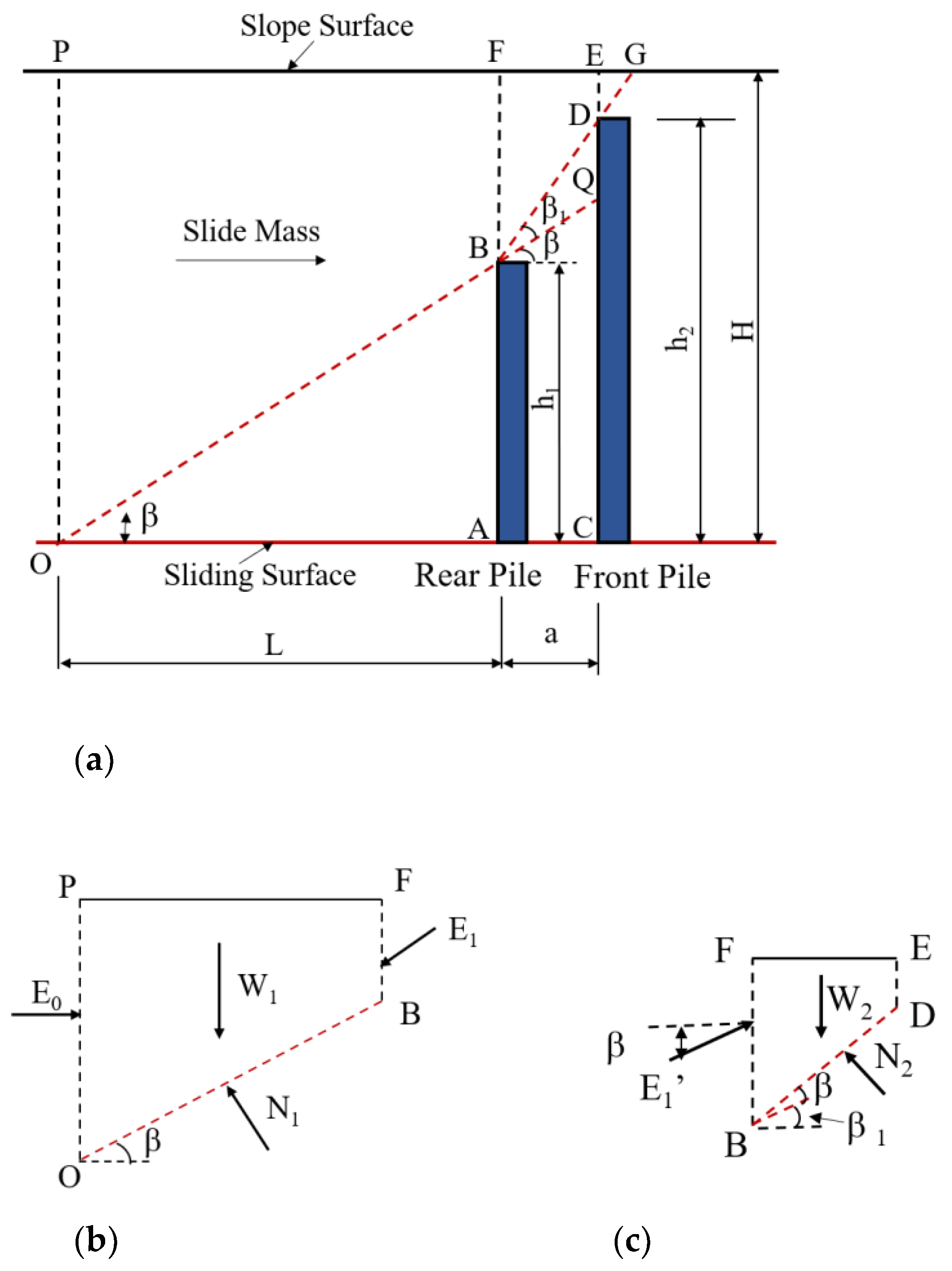
2. Analytical Model
3. Calculation Method
3.1. Fundamental Assumption
3.2. Establishment of Calculation Method
3.2.1. Calculation When the Sliding Surface Is Horizontal
3.2.2. Calculation When the Sliding Surface Is Tilted
4. Instance Analysis
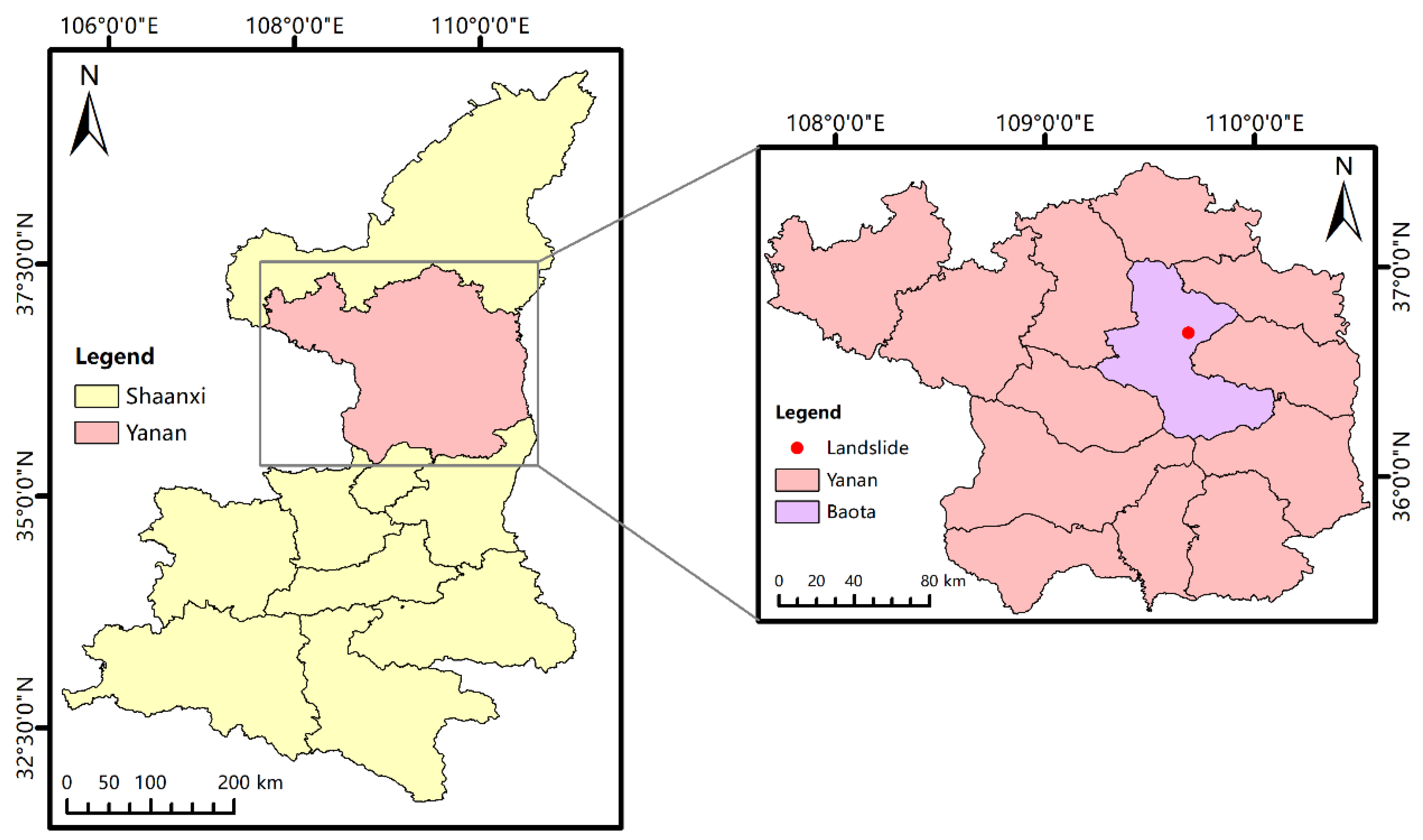
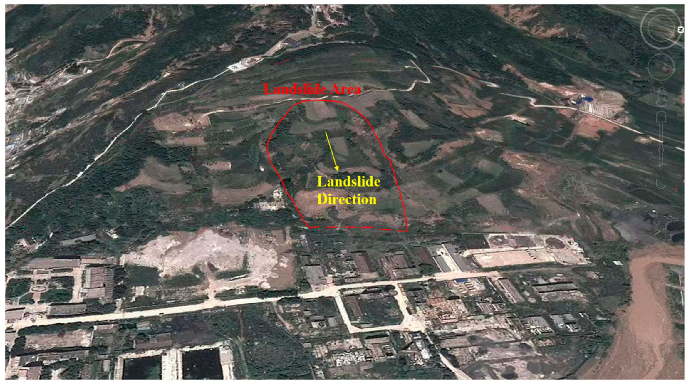
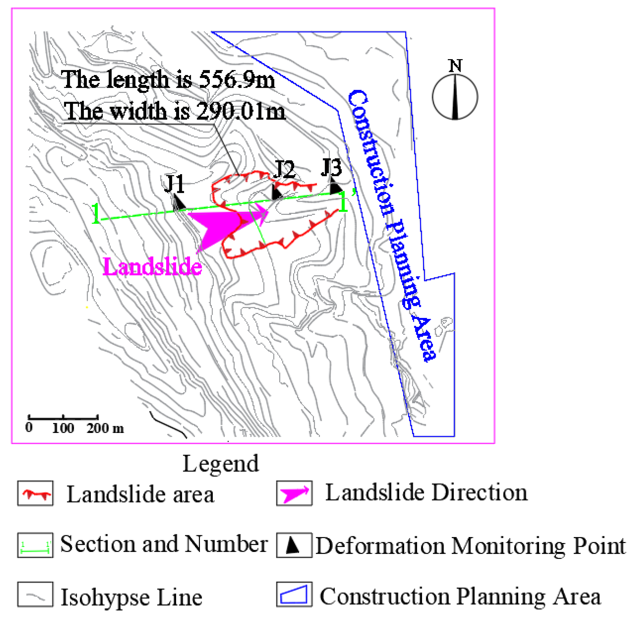
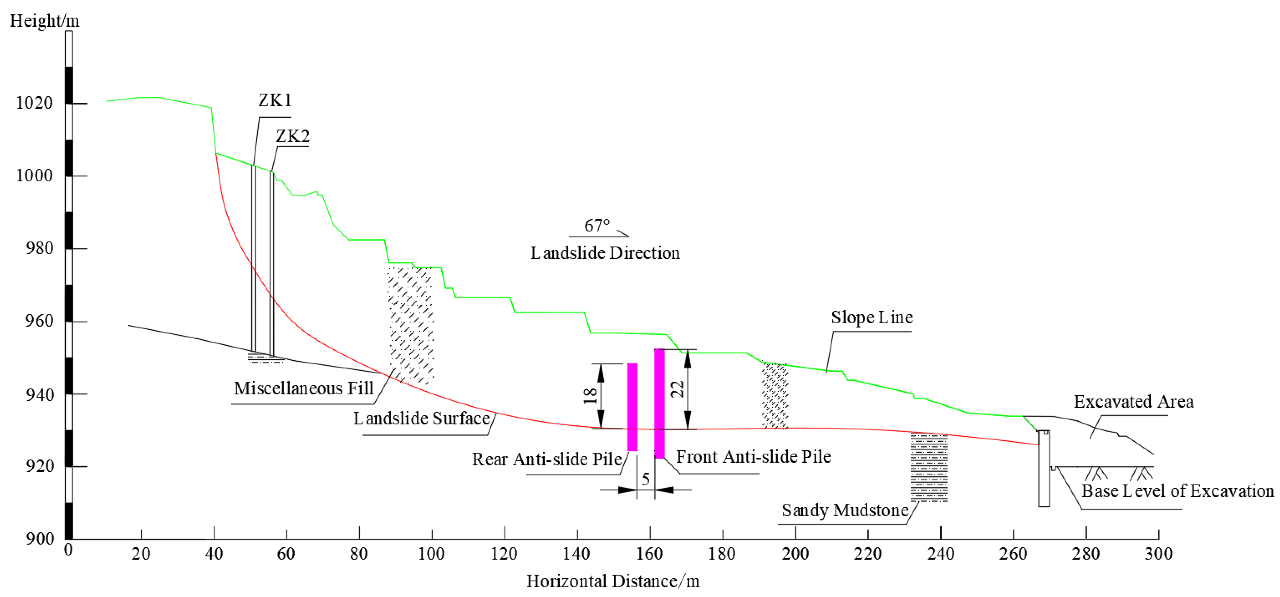
4.1. Project Profile
4.2. Stability Analysis
- (1)
- Malan Loess (Q3eol): It is light yellow; the soil is mainly silty soil, low density and humidity. It contains a small amount of calcium nodules and calcium streaks, and its layer thickness is 0.80–19.80 m.
- (2)
- Paleosol (Q3el): It is brown, the soil is mainly silty clay and the humidity and density are moderate. White calcareous streaks and a few calcareous nodules are seen. Its layer thickness is 1.30–13.80 m.
- (3)
- Lishi loess (Q2eol): The soil is yellowish-yellow and mainly silt. Contains small amounts of calcareous nodules and ferromanganese streaks, containing mica. The soil layer is 1.70–36.40 m thick.
- (4)
- Paleosol (Q2el): The soil is yellowish-brown, mainly silty clay. There are a few white stripes and iron and manganese stripes, and the bottom contains a small amount of calcium nodules. The soil layer is 3.30–13.00 m thick.
- (5)
- Lishi loess (Q2eol): The soil is yellowish-yellow, mainly silty soil. Inside can be seen wormhole, pinhole development, iron and manganese spots. The soil layer is 3.20–15.60 m thick.
4.3. Construction Design
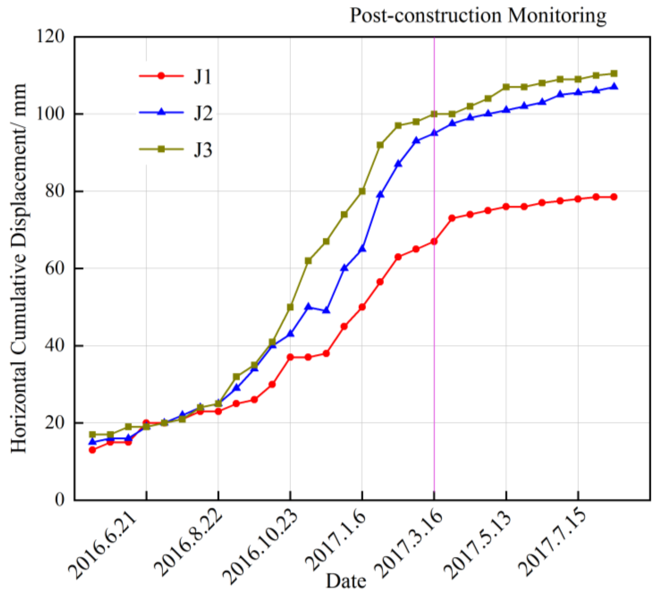
5. Results and Discussion
Author Contributions
Funding
Institutional Review Board Statement
Informed Consent Statement
Data Availability Statement
Conflicts of Interest
References
- National Bureau of Statistics. Available online: https://www.stats.gov.cn/ (accessed on 1 December 2023).
- Zhenwei, P.; Tingkai, N.; Hao, W.; Yanjun, Z.; Chaofeng, Z.; Rui, W. Research progress of landslide geological disaster emergency management technology. J. Disaster Prev. Mitig. Eng. 2021, 41, 1382–1394. [Google Scholar] [CrossRef]
- Derly, G.F.E.G.; Edier, A. Spatial and temporal landslide distributions using global and open landslide databases. Nat. Hazards 2023, 117, 25–55. [Google Scholar] [CrossRef]
- Tao, L.; Gang, C. Analysis of factors influencing anti-slip pile support in tunnel landslide systems for tunnels with different burial depths. Transp. Geotech. 2023, 42, 101079. [Google Scholar] [CrossRef]
- Froude, M.J.; Petley, D.N. Global fatal landslide occurrence from 2004 to 2016. Nat. Hazards Earth Syst. Sci. 2018, 18, 2161–2181. [Google Scholar] [CrossRef]
- Kai, L. Research on Physical Model Test of Anti-Sliding Micro Pile. Ph.D. Thesis, Chang’an University, Xi’an, China, 2022. [Google Scholar] [CrossRef]
- Fengwu, G.; Chen, L.; Wenjuan, G.; Chenguang, L.; Zhanying, F.; Yinbo, Z. Geological Brigade of Hebei Geology and Mineral Exploration Bureau; Improvement of Stiffness calculation and displacement analysis of Double row pile and double beam combined support. Hydrogeol. Eng. Geol. 2022, 49, 109–116. [Google Scholar] [CrossRef]
- Yong, L.; Yingren, Z.; Keqin, C. Discussion on the concept of “skid-resistant short pile” and its mechanical influence. J. Undergr. Space Eng. 2009, 5, 608–615. [Google Scholar]
- Shiguo, X. A simplified approach for stability analysis of slopes reinforced with one row of buried stabilizing piles. Bull. Eng. Geol. Environ. 2017, 76, 1371–1382. [Google Scholar] [CrossRef]
- Yuping, Y.; Shiguo, X. A calculation method for the buried depth of stabilizing piles in reinforced slopes. Int. J. Numer. Anal. Methods Geomech. 2020, 44, 1077–1092. [Google Scholar] [CrossRef]
- Wenfeng, L.; Zhijun, Z. Application of buried double-row piles in soil landslide control engineering. J. South China Univ. 2018, 32, 37–43. [Google Scholar] [CrossRef]
- Shiren, Z. Design of Sinking anti-slide pile. Chongqing Archit. 2003, 1, 22–24. [Google Scholar]
- GB 50843-2013; Technical Specifications for Construction Slope Engineering. China Architecture & Building Press: Beijing, China, 2013.
- GB/T38509-2020; Design Code for Landslide Control. China Architecture & Building Press: Beijing, China, 2020.
- Yuping, Y. Thrust algorithm of load section and buried section of sinking pile in overtopping failure mode. Hydrogeol. Eng. Geol. 2023, 50, 76–84. [Google Scholar] [CrossRef]
- Zhiwen, X. Force distribution of deep-buried anti-slide pile. China Railw. Sci. 2000, 01, 50–58. [Google Scholar]
- Wenjie, L. Research on Finite Element Design Method and Large-Scale Physical Model Test of Landslide Reinforced by Pile Sinking. Ph.D. Thesis, Wuhan Institute of Rock and Soil Mechanics, Chinese Academy of Sciences, Wuhan, China, 2006. [Google Scholar]
- Wenjie, L.; Yingren, Z.; Xiating, F. Discussion on finite element design method of buried pile. Chin. J. Rock Mech. Eng. 2006, S1, 2924–2929. [Google Scholar]
- Yakun, S.; Yingren, Z.; Wenjie, L. Numerical analysis of mechanical model test of submerged anti-slide pile. Rock Soil Mech. 2007, 28, 63–68. [Google Scholar] [CrossRef]
- Guiyong, A.O.; Yufang, Z.; Shangyi, Z.; Yingren, Z.; Yongfu, W. Analysis of landslide thrust borne by buried anti-slide pile. Eng. Mech. 2020, 37, 187–192. [Google Scholar]
- Xu, W.; Echuan, Y.; Meijun, L. Simulation of internal force distribution between piles in buried double-row pile-soil system. Coal Geol. Explor. 2006, 04, 57–60. [Google Scholar]
- Meijun, L.; Echuan, Y. Research on Landslide thrust distribution of embedded Double-row anti-slide piles. In Proceedings of the 9th National Conference on Rock Dynamics, Zhengzhou, China, 21 October 2005. [Google Scholar]
- Junfei, L. Analysis and Research on Working Mechanism of Double-Row Buried Anti-Slide Pile. Ph.D. Thesis, Chongqing University, Chongqing, China, 2009. [Google Scholar]
- Yuping, Y. Research on Mechanism and Calculation Method of Landslide Reinforcement with Full-Length Combined Anti-Slide Piles with Sunken Back and Front Rows. Ph.D. Thesis, Southwest Jiaotong University, Chengdu, China, 2022. [Google Scholar] [CrossRef]
- Weihang, O.; Si-Wei, L.; Yi, Y. An improved morgenstern-price method using gaussian quadrature. Comput. Geotech. 2022, 148, 104754. [Google Scholar] [CrossRef]
- Krisnasiwi, I.F.; Sundari, W. Analysis of slope stability based in the spencer method on the ring road section, Sikumana. Kupang City. J. Phys. Conf. Ser. 2021, 2017, 012017. [Google Scholar] [CrossRef]
- Boxiang, L. Comprehensive Ground Penetrating Radar (GPR) Method and Janbu Method Study of Road Slope Geological Disaster. Ph.D. Thesis, China University of Geosciences, Beijing, China, 2021. [Google Scholar] [CrossRef]


| Stratum | Natural Condition | Saturation Condition | ||||
|---|---|---|---|---|---|---|
| γ (kN/m3) | C (kPa) | Φ (°) | γ (kN/m3) | C (kPa) | Φ (°) | |
| Malan loess | 19.5 | 13.5 | 19.5 | 20.1 | 9.8 | 13.0 |
| Paleosol | 19.6 | 18.0 | 20.0 | 20.2 | 15.0 | 10.0 |
| Lishi Loess | 19.9 | 15.0 | 23.0 | 20.3 | 10.2 | 15.0 |
| Paleosol | 19.4 | 18.0 | 20.0 | 20.3 | 15.0 | 10.0 |
| Lishi Loess | 19.9 | 15.0 | 23.0 | 20.4 | 10.2 | 15.0 |
| Slipband | 19.7 | 13.0 | 12.0 | 21.9 | 10.0 | 10.0 |
| Selection Condition | Stability Coefficient | Surplus Sliding Force (KN/m) | Steady State |
|---|---|---|---|
| Condition 1 | 1.387 | 1900 | stabilization |
| Condition 2 | 1.089 | 1711 | understable |
| Condition | Row Spacing (d: Diameter of the Pile) | Load-Bearing Section of Rear Pile | Load-Bearing Section of Front Pile | Initial Rupture Angle | Secondary Rupture Angle |
|---|---|---|---|---|---|
| 1 | 2d | 18 m | 21.107 m | 35° | 18.239° |
| 3d | 21.175 m | 18.238° | |||
| 4d | 21.656 m | 18.235° | |||
| 2 | 2d | 19 m | 23.697 m | 8.857° | |
| 3d | 23.902 m | 8.857° | |||
| 4d | 23.936 m | 8.857° | |||
| 3 | 2d | 20 m | 24.039 m | 24.526° | |
| 3d | 24.214 m | 24.525° | |||
| 4d | 24.241 m | 24.525° | |||
| 4 | 2d | 21 m | 23.699 m | 27.838° | |
| 3d | 23.471 m | 27.837° | |||
| 4d | 24.194 m | 27.839° | |||
| 5 | 2d | 22 m | 23.532 m | 18.261° | |
| 3d | 23.684 m | 18.260° | |||
| 4d | 23.637 m | 18.260° | |||
| 6 | 2d | 23 m | 25.248 m | 24.543° | |
| 3d | 25.237 m | 24.543° | |||
| 4d | 25.322 m | 24.543° | |||
| 7 | 2d | 24 m | 24.632 m | 27.833° | |
| 3d | 24.962 m | 27.834° | |||
| 4d | 25.000 m | 27.834° | |||
| 8 | 2d | 25 m | 25.670 m | 30.834° | |
| 3d | 25.711 m | 30.834° | |||
| 4d | 25.747 m | 30.834° |
Disclaimer/Publisher’s Note: The statements, opinions and data contained in all publications are solely those of the individual author(s) and contributor(s) and not of MDPI and/or the editor(s). MDPI and/or the editor(s) disclaim responsibility for any injury to people or property resulting from any ideas, methods, instructions or products referred to in the content. |
© 2024 by the authors. Licensee MDPI, Basel, Switzerland. This article is an open access article distributed under the terms and conditions of the Creative Commons Attribution (CC BY) license (https://creativecommons.org/licenses/by/4.0/).
Share and Cite
Li, X.; Wang, M.; Yang, W.; Xu, R.; Pang, X. Study on Optimal Pile Length in Load Section of Double-Row Buried Pile under Overtopping Failure Mode. Appl. Sci. 2024, 14, 438. https://doi.org/10.3390/app14010438
Li X, Wang M, Yang W, Xu R, Pang X. Study on Optimal Pile Length in Load Section of Double-Row Buried Pile under Overtopping Failure Mode. Applied Sciences. 2024; 14(1):438. https://doi.org/10.3390/app14010438
Chicago/Turabian StyleLi, Xunchang, Mingming Wang, Wei Yang, Rui Xu, and Xuqing Pang. 2024. "Study on Optimal Pile Length in Load Section of Double-Row Buried Pile under Overtopping Failure Mode" Applied Sciences 14, no. 1: 438. https://doi.org/10.3390/app14010438
APA StyleLi, X., Wang, M., Yang, W., Xu, R., & Pang, X. (2024). Study on Optimal Pile Length in Load Section of Double-Row Buried Pile under Overtopping Failure Mode. Applied Sciences, 14(1), 438. https://doi.org/10.3390/app14010438