Article

Simulation Study and Engineering Application of Weakening Mine Pressure Behavior in Stope through Ground Fracturing Thick and Hard Rock Strata

1
College of Mining Engineering, Taiyuan University of Technology, Taiyuan 030024, China
2
Key Laboratory of Shanxi Province for Mine Rock Strata Control and Disaster Prevention, Taiyuan University of Technology, Taiyuan 030024, China
3
Shanxi Province Coal-Based Resources Green and High-Efficiency Development Engineering Center, Taiyuan 030024, China
4
State Key Laboratory of Coal Mine Disaster Dynamics and Control, Chongqing University, Chongqing 400044, China
5
School of Mechanical and Mining Engineering, The University of Queensland, St. Lucia, QLD 4072, Australia
*
Authors to whom correspondence should be addressed.
Appl. Sci. 2024, 14(1), 415; https://doi.org/10.3390/app14010415
Submission received: 2 November 2023 / Revised: 20 December 2023 / Accepted: 27 December 2023 / Published: 2 January 2024
(This article belongs to the Special Issue Advanced Underground Coal Mining and Ground Control Technology)

Abstract

:
Fracturing hard roofs by ground hydraulic action is an important control technology for the strong mine pressure in the stope. In this paper, a new simulation method, “separate + interface,” is proposed, and two physical simulation experiments are conducted; the phenomenon of increased goaf pressure and decreased front abutment pressure is discovered after fracturing in the key strata, and then the influence of different fractured crack shapes on the front abutment pressure and the goaf stress is revealed. The results are as follows: Firstly, the separation under the high-level hard strata blocks the transmission of overburden load to the goaf, leading to the high-stress concentration of the coal seam, which is the main reason for the large deformation of roadways and the breakage of a single hydraulic prop in the roadway. Secondly, the weakening effect of mine pressure differs when hard rock strata are fractured artificially with different types of cracks. The peak value of abutment pressure is reduced from 24.91 to 20.60 MPa, 17.80 MPa, and 16.13 MPa with the vertical crack spacing of 20 m, 15 m, and 10 m, respectively, and the related goaf pressure is increased from 2.61 to 3.54 MPa, 3.91 MPa, and 4.34 MPa, respectively. The peak value of abutment pressure decreased from 24.79 to 22.08 MPa, 19.88 MPa, and 17.73 MPa. The related goaf pressure increased from 2.61 to 3.39 MPa, 3.81 MPa, and 4.43 MPa, respectively, with the key strata also fractured into two horizontal layers, three horizontal layers, and four horizontal layers with horizontal fractures. Thirdly, after the hard roof is fractured above the No. 8202 working face, the first breaking step distance of the main roof decreased from 112.6 to 90.32 cm, while the first breaking step distances of KS2 and KS3 decreased from 106.3 and 135.8 cm to 93.5 cm and 104.8 cm, respectively, and the goaf pressure also increased. Compared to the adjacent unfractured No. 8203 working face, the mine pressure intensity of the No. 8202 working face is significantly reduced. The research results can provide useful guidance for the treatment of strong mine pressure.

1. Introduction

As one of the most basic fossil energy sources, coal provided 29% of the world’s primary energy demand, 41% of the world’s electricity, and 44% of the direct input of industrial production in 2015 [1,2], and coal will maintain this level for a long time due to the characteristics of extensive coal resources, huge reserves, and low mining costs [2]. Coal is a non-renewable resource, and improving its recovery rate positively impacts energy savings, enterprise efficiency, and the sustainable development of human society. The safe and efficient mining of coal resources has always been a research hotspot in mining. The strong mine pressure due to the fracture and movement of the hard roof layer seriously affects mine safety. It will induce a series of disasters, including crushed hydraulic supports, rock bursts, coal and gas outbursts, etc., causing property damage and casualties. This adverse effect is even more severe under the dual influence of ultra-thick coal seams and hard roofs [3,4]. Given the research on the inducing mechanism of strong mine pressure behavior and the hard roof fracturing weakening method, many fruitful studies have been conducted, which provides an essential reference for further in-depth research in this paper. Xu Bin et al. derived the calculation expression of the breaking angle of the key stratum based on elasticity and rock mass mechanics [5]. Zhu et al. proposed a structural mechanics model of a “triangular plate,” revealing the fracture characteristics of high-level key strata [6]. Jiang et al. established a mechanical model of the structure of high-level hard and thick rock strata and proposed that a small energy microseismic is mainly distributed in the strata below the high-level thick key stratum. In contrast, the enormous energy microseismic activity occurs in the process of fracture and instability of the thick key stratum [7,8]. Yu et al. obtained the relationship between fracturing area with fracturing time and flow rate through the hydraulic fracturing test of large-scale authentic triaxial in situ specimens [9]. Based on the theory of the key stratum, Li et al. investigated the broken blocks’ rotational speed of voussoir beam structures. Then, the effect of rotational speed on the occurrence of strong rock pressure in stope was revealed [10,11,12,13]. Gao et al. explored the weakening impact of ground hydraulic fracturing technology on a high-key stratum through in situ monitoring and numerical simulation [14,15]. Adequate research on the breaking laws of hard roof, structure morphology formed by the broken blocks [16,17,18,19], factors affecting the stability of the structure [20,21,22,23,24,25], the blasting and hydraulic fracturing methods of the hard roof [26,27,28,29,30], expansion characteristics and influence factors of hydraulic fracturing fractures [31,32,33,34], a quantitative description method for crack propagation law [35,36,37], movement characteristics of key strata after fracturing and the influence of fracturing cracks morphology on structural stability [38,39,40,41] etc., have been conducted.
In summary, the existing research primarily uses theoretical calculations and similar simulation experiments to study the influence characteristics of the movement of thick and hard key stratum on the appearance of strong mine pressure. Then, it provides the corresponding control measures by combining underground hydraulic fracturing and high-level hard roof ground fracturing. In the numerical simulation method, finite and discrete elements are used to study the phenomenon of strong mine pressure and its weakening effect on the working face before and after the fracturing of thick and hard rock strata, respectively. However, what is the mechanical mechanism for reducing the intensity of mine pressure after ground fracturing the high-level key strata? What changes will occur in the distribution of mining-induced stress and load transmission path in the overlying rock after fracturing of the high-level key strata? Further research is still needed to reveal the mechanical mechanism of ground fracturing hard roofs to reduce the intensities of mine pressure.
Because of this, the stress distribution and load transfer mechanism after fracturing hard rock strata by ground hydraulic action have been thoroughly investigated. Firstly, a new method is proposed to simulate the separation and fracture of key strata formation. Secondly, the distribution characteristics and transfer law of mining-induced stress, especially the goaf stress and the front abutment pressure, are explored along with the advancing of the mining working face. Thirdly, the effects of fracturing hard rock strata by vertical cracks with different spacing and horizontal cracks with varying layer thicknesses on load transfer and mining-induced stress distribution are further analyzed. Based on this, the engineering practice of weakening mine pressure intensities through ground fracturing in high-level key strata has been carried out in No. 8202, the working face of Tongxin Coal Mine in Datong Mining Area, China. Variation patterns of the hydraulic support resistance after fracturing high-level key strata indicate that the intensities of mine pressure behavior have been significantly reduced. This study provides essential guidance for formulating a key strata fracturing plan and the efficient weakening of strong mine pressure.

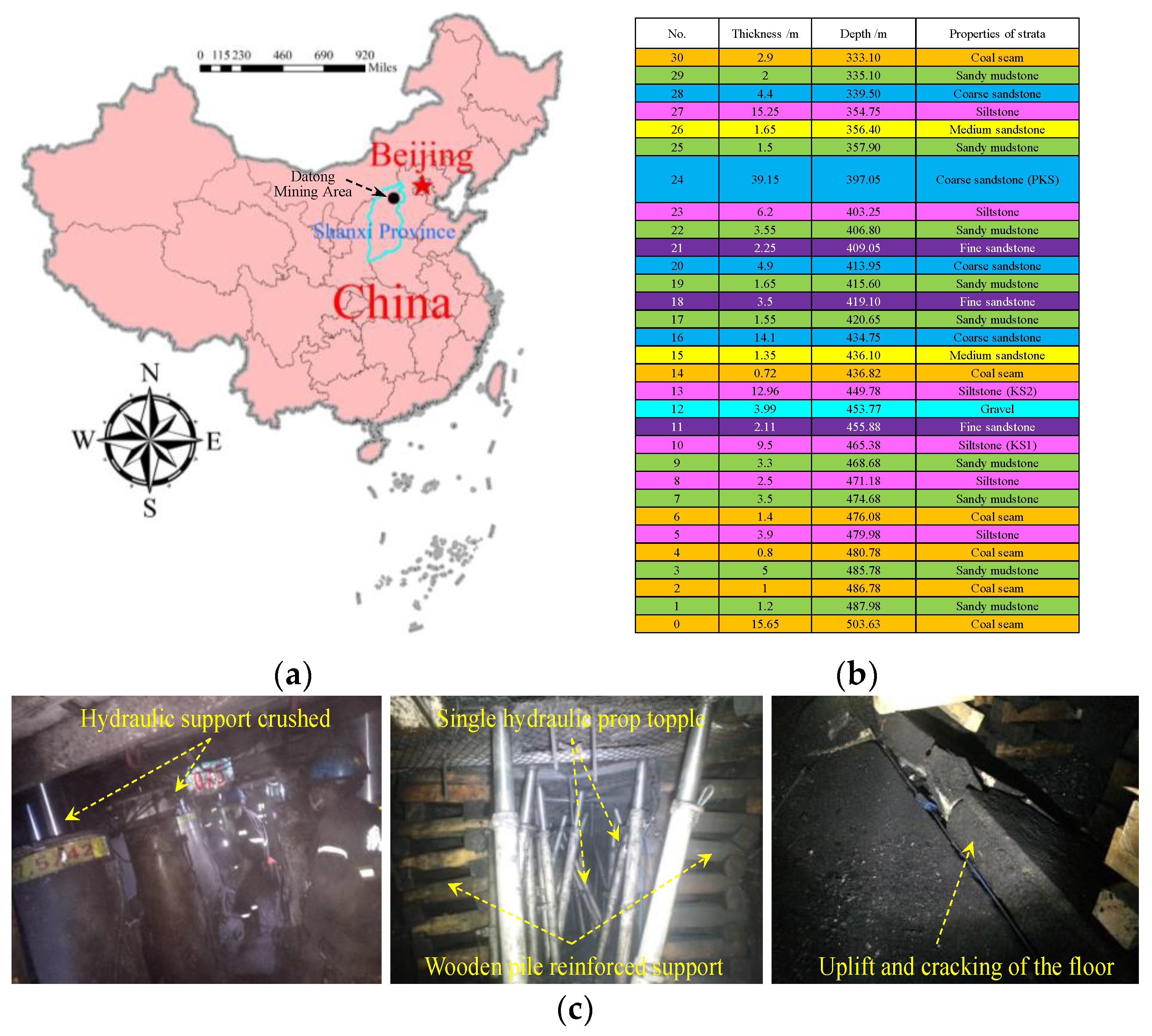
2. Engineering Background

The Tongxin Coal Mine is located in the southern part of the Datong Coalfield in Shanxi Province, China, as shown in Figure 1a. The No. 8202 working face is located in the north second panel, with a strike length of 2100~2200 m and dip length of 200 m, an average buried depth of 479.12 m, an average dip angle of 1.5° and an average thickness of 11~15 m. The No. 8202 working face is the connecting working face of the No. 8203 working face, both located in the north second panel, where the No. 8203 working face is the first mining face of the entire second-panel area. The roof of the No. 8202 working face contains multiple layers of sandstone with high thickness and strength, forming a hard roof group, and the formation column is shown in Figure 1b. There is no aquifer in the overburden, and only some areas have accumulated a small amount of water in the above goaf of the overlying Jurassic coal seam, which has also been drained up ahead. Due to the widespread existence of multi-layer hard roofs, intense mine pressure occurs frequently, such as support crushed, hydraulic prop topple, and floor heave in the roadway, as shown in Figure 1c. Therefore, it is urgent to reveal the influence of thick hard roofs on the distribution of mining-induced stress and explore and develop corresponding control measures.

3. Bearing Characteristics of Thick and Hard Strata

3.1. Influence of Key Strata on Strata Movement

According to the key stratum theory, the overlying strata present the characteristics of the overall movement as a group, and the lowest stratum controls the overlying strata. The key stratum is generally the strata with a larger thickness and higher strength, and the key strata in the overlying rock layer of the No. 8202 working face are marked in Figure 1b. After the key stratum is broken, the overlying strata it controls will break and sink synchronously, which has been verified by many scholars and engineering practices. The key stratum theory is the most basic and essential strata control theory for underground coal mining in China and has been widely used globally [42,43,44]. The control effect of key strata is shown in Figure 2.
It can be seen that when the high-key stratum is suspended but has not yet reached the limit breaking span, the separation will occur below the high-level key strata. At this time, the high-level key stratum forms an elastic foundation beam, and the load of the overlying strata controlled by the key stratum is transmitted downward through the elastic foundation, developing abutment pressure of the working face finally, as shown in Figure 3a. When the high-key stratum reaches the ultimate breaking span or has not reached the ultimate breaking span but has been fractured ahead artificially, the deflection of the key stratum will significantly increase, and the separation space below the key stratum is gradually closed, inducing the overburden load transfers to the collapse strata in goaf. Then, a new overburden load transfer path is formed, as shown in Figure 3b. Therefore, to avoid colossal energy release and high-stress concentration caused by the natural fracture of the high key stratum with a considerable span length, the high key stratum is fractured artificially in advance, which is an essential means to reduce the intensities of mine pressure.

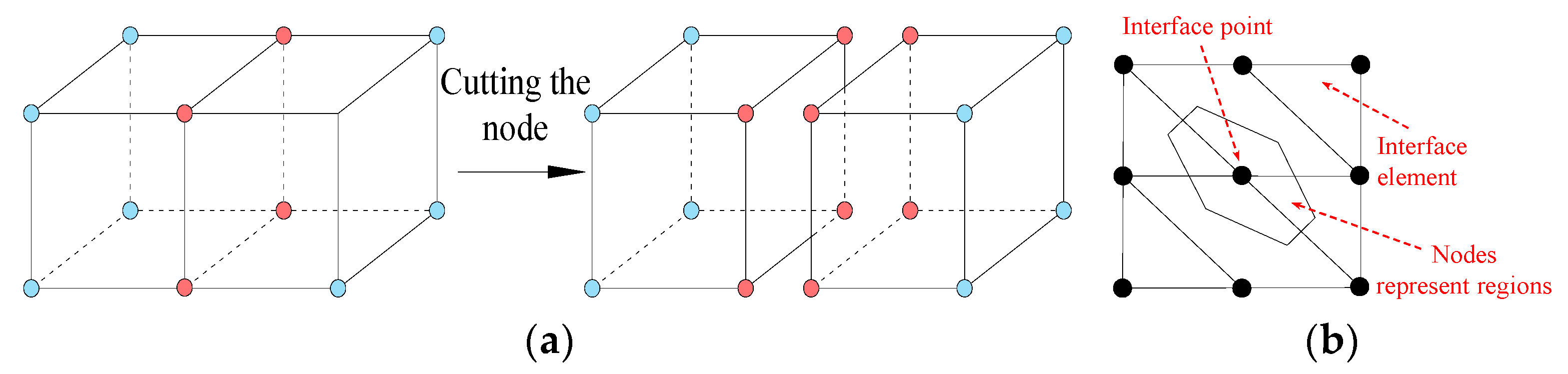
3.2. Key Stratum Fracturing Simulation Methods

In FLAC3D, the entities are composed of nodes, edges, faces, and zones, which can be manipulated and processed by discretization and separation. GEN Separate can be used to separate entities and create new independent chunks, which are often adopted to simulate the generation and evolution of rock mass fractures and groundwater permeability. Gen separate is used to separate the defined group, and then there are two pink nodes on the common plane, which can realize the division of the exact location point on the common plane, as shown in Figure 4a. After this operation, the command “Interface” can be used to generate a new interface, as shown in Figure 4b, which makes it possible to simulate fracturing in key strata numerically.

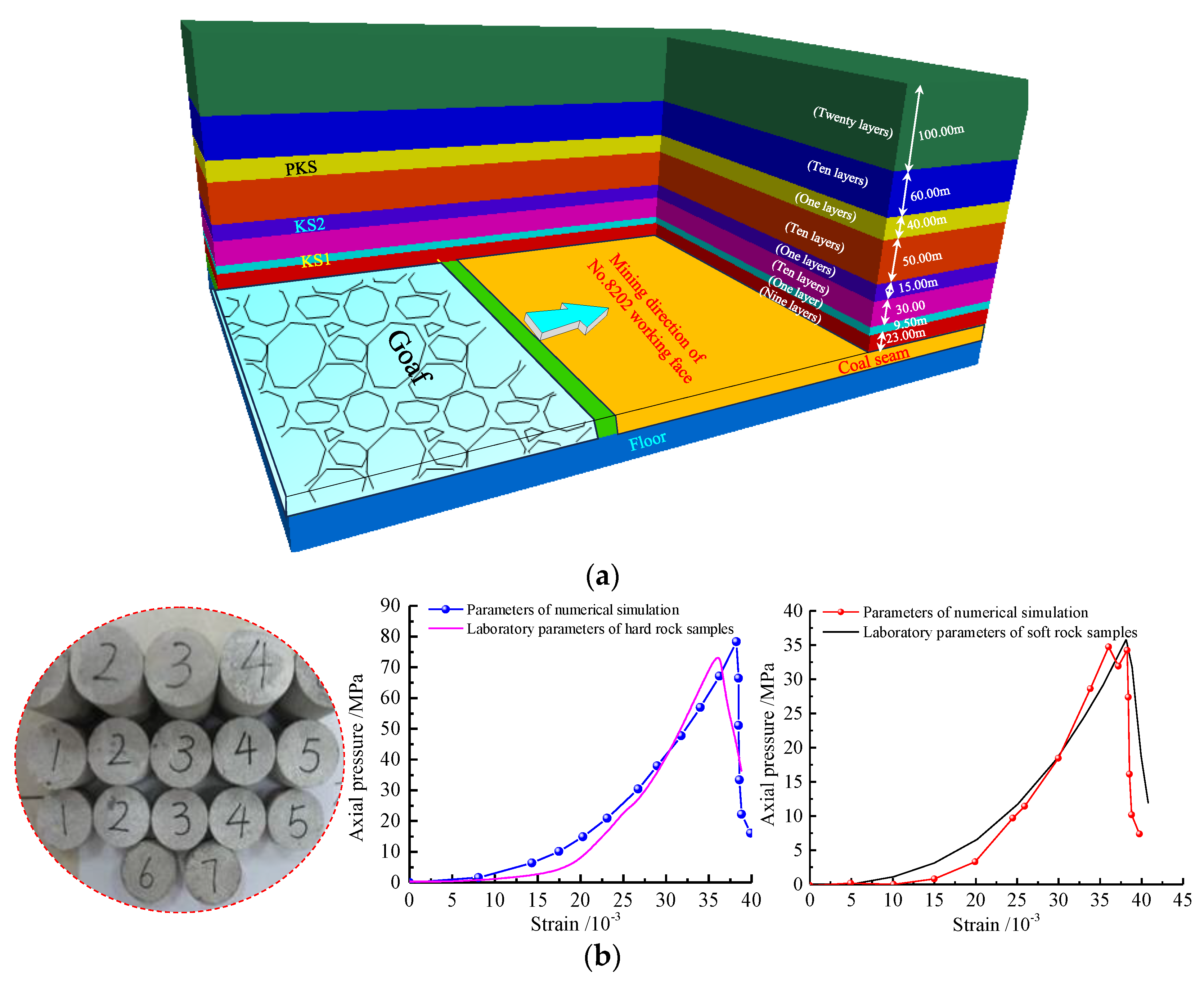
3.3. Numerical Simulation Model

According to the mining geological conditions of the No. 8202 working face, a FLAC3D numerical calculation model is established, and the model length (X) × width (Y) × height (Z) is 800 m × 600 m × 350 m, as shown in Figure 5a. The physical and mechanical parameters of the rock formation in the numerical simulation are shown in Table 1.
The displacement constraint is adopted for the surrounding and bottom boundaries of the model, the upper part is the free boundary, and a 150 m compensation load is applied to simulate the 500 m buried depth of the No. 8202 working face. To study the load-bearing characteristics of the key stratum and its separation effects before fracture, the aforementioned “move and remove method” is used to establish the contact surface. The overburden’s key stratum, floor, and coal seam adopts the Mohr–Coulomb model. Meanwhile, referring to the laboratory mechanical testing results of rock samples, the numerical simulation parameters were calibrated using the trial-and-error method [45,46,47]. Due to space limitations, taking hard rocks and soft rocks as examples, it can be seen that the numerical simulation parameters used can accurately reflect the bearing characteristics of different overlying strata, as shown in Figure 5b.

4. Evolution Law of Front Abutment Pressure and Goaf Stress without Fracturing Conditions

The corresponding goaf pressure and front abutment pressure with the advancing of the No. 8202 working face are extracted, and the vertical stress in the coal seam is selected as the monitoring indicator for the front abutment pressure. In contrast, the collapsed coal gangue in the goaf is updated to the Salamon model, and the vertical stress of the Salamon model is used as the goaf pressure, as shown in Figure 6. When the advancing distance is 50 m, the KS1 is not broken, the goaf stress is basically equal to zero, the stress concentration is formed at the working face, and the open–off cut and the peak value of the front abutment pressure is 22.52 MPa, as shown in Figure 6a. When the advancing distance is 100 m, the KS1 is broken, and KS1 and its controlled strata sink synchronously. At the same time, there is an uncoordinated deformation between KS2 and its underlying rock layer (that is, the strata controlled by KS1), and the separation appears. The width of the stress recovery zone in goaf is 32 m, the peak value of goaf stress is 0.75 MPa, and the peak value of the front abutment pressure is 20.76 MPa, as shown in Figure 6b. When the advancing distance is 150 m, the peak value of the goaf stress increases to 1.43 MPa, the width of the stress recovery zone rises to 81.5 m, and the peak value of front abutment pressure is 21.83 MPa, as shown in Figure 6c. When the advancing distance is 200 m, KS2 is broken, KS2 and its controlled rock layer sink synchronously, the peak value of the goaf stress increases to 2.29 MPa, the width of the stress recovery zone rises to 146 m, and the peak value of the front abutment pressure is 23.23 MPa, as shown in Figure 6d. When the advancing distance is 250 m, the peak value of the goaf stress further increases to 2.61 MPa, the width of the stress recovery zone rises to 198 m, and the peak value of abutment pressure is 24.91 MPa, as shown in Figure 6e. When the advancing distance is 300 m, the peak value of the goaf stress further increases to 2.59 MPa, the width of the stress recovery zone rises to 215 m, and the peak value of the abutment pressure is 25.32 MPa, as shown in Figure 6f.

5. Weakening Effect of Different Fracturing Schemes on Mining-Induced Stress

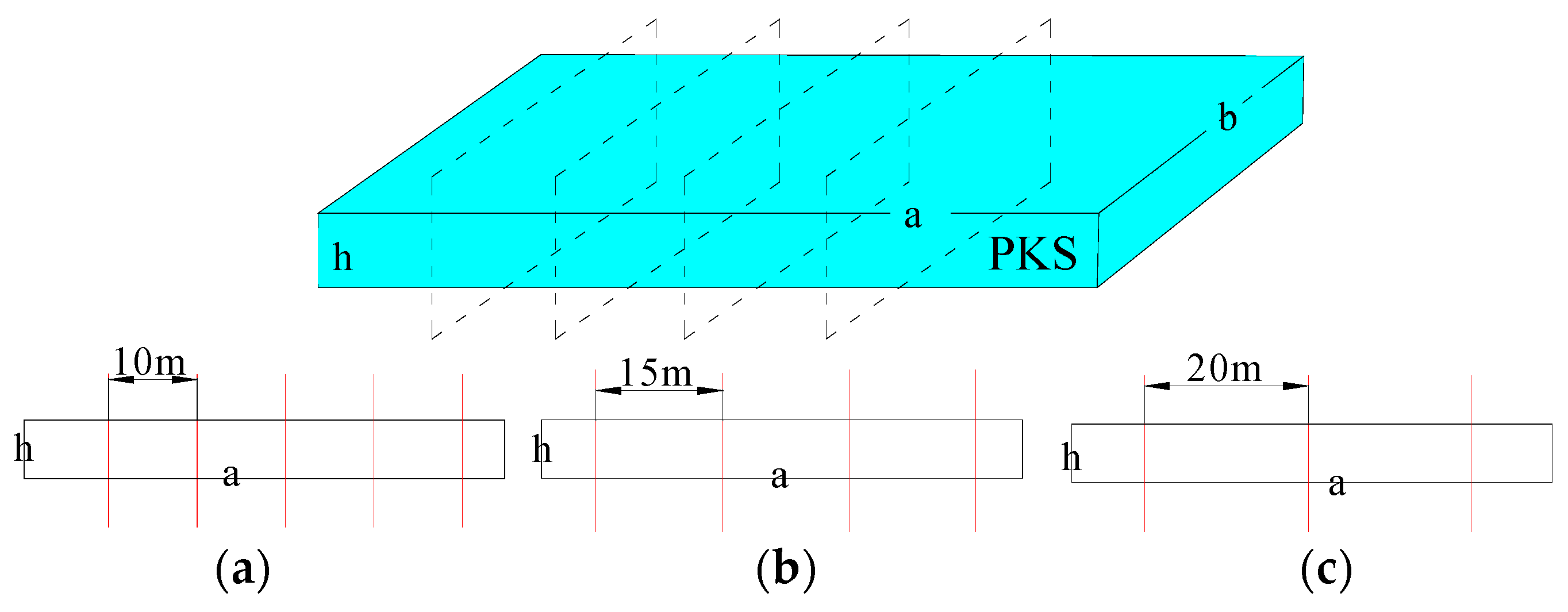
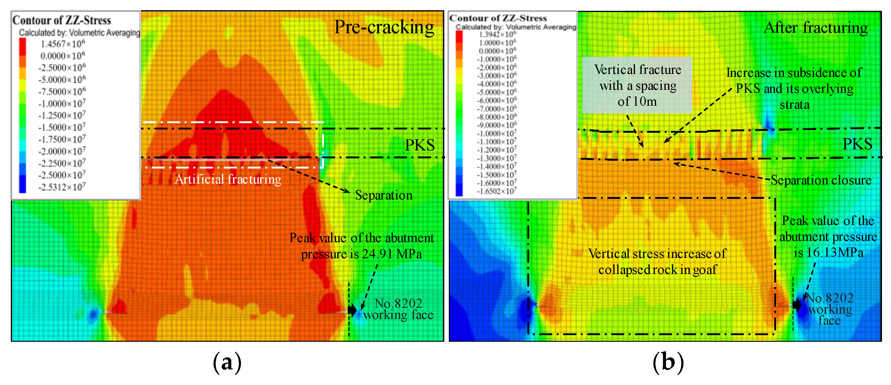
5.1. Vertical Fractures with Different Spacing

A large number of engineering practices show that fracturing in the high-level key stratum is an effective means to alleviate the intensity of strong mine pressure behavior [48,49], and the different fracturing schemes of the high-level key stratum also have a significant impact on the distribution of the front abutment pressure and the goaf stress. Taking the advancing distance 250 as an example, those mentioned above in the “Separate + interface” method are used to cut the PKS to form different crack schemes artificially. Then, the corresponding change patterns of the front abutment pressure and the goaf stress are investigated. The method of vertical cracks with different spacing to cut PKS is shown in Figure 7.
The corresponding distribution curve of the front abutment pressure and the goaf stress are shown in Figure 8. When the PKS is not fractured, the peak value of front abutment pressure is 24.91 MPa, as shown in Figure 8a, the width of the stress recovery zone in the goaf area is 198 m, and the peak value of goaf stress is 2.61 MPa, as shown in Figure 8e,f. After fracturing the PKS with a vertical crack spacing of 10 m, the peak value of front abutment pressure is reduced to 16.13 MPa, as shown in Figure 8b. In comparison, the width of the stress recovery zone in the goaf area is increased to 220 m, and the peak value of goaf stress is increased to 4.34 MPa, as shown in Figure 8e,f. After fracturing the PKS with a vertical crack spacing of 15 m, the peak value of the front abutment pressure is reduced to 17.80 MPa, as shown in Figure 8c, the width of the stress recovery zone in the goaf area is increased to 217 m, and the peak value of goaf stress is increased to 3.91 MPa, as shown in Figure 8e,f. After fracturing the PKS with a vertical crack spacing of 20 m, the peak value of the abutment pressure is further reduced to 20.60 MPa, as shown in Figure 8d, the width of the stress-recovery zone in the goaf area is increased to 215 m, and the peak value of goaf stress is increased to 3.54 MPa, as shown in Figure 8e,f.
It can be seen that the vertical subsidence of the high key stratum and its control rock layer increase fleetingly after fracturing PKS with a vertical fracture. At the same time, a new stress transfer path is formed with the closure of the separation space below PKS, which leads to more overlying rock loads being transferred to the collapsed rock mass in the goaf, resulting in the increase in goaf stress and the decrease in the front abutment pressure. This is the mechanical essence of reducing the front abutment pressure of the working face after fracturing the high-level key stratum, which also reasonably explains why the mine pressure of the roadway of the working face can be alleviated after fracturing the high-key stratum.

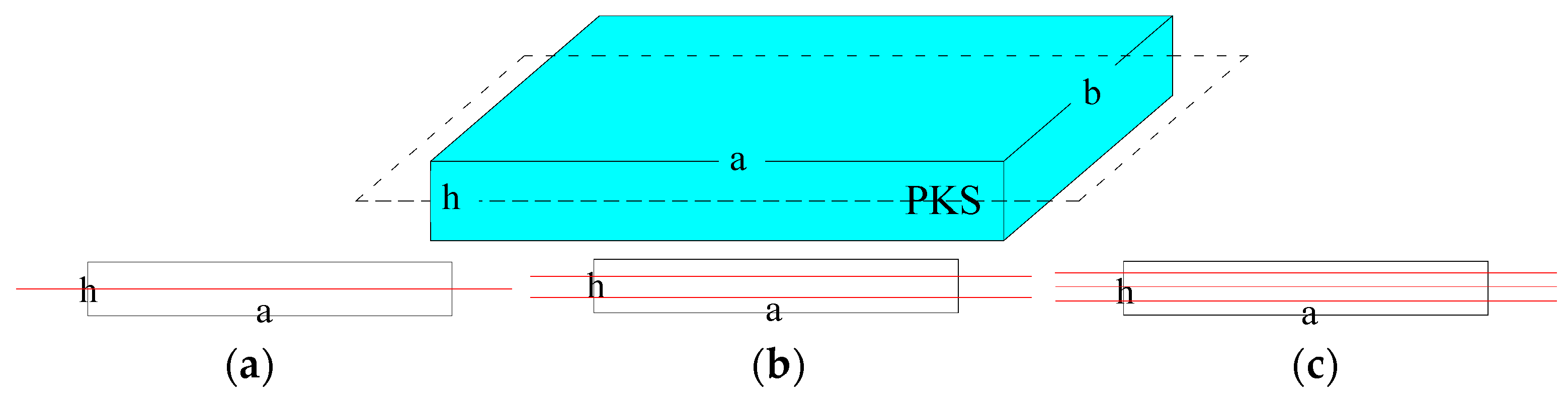
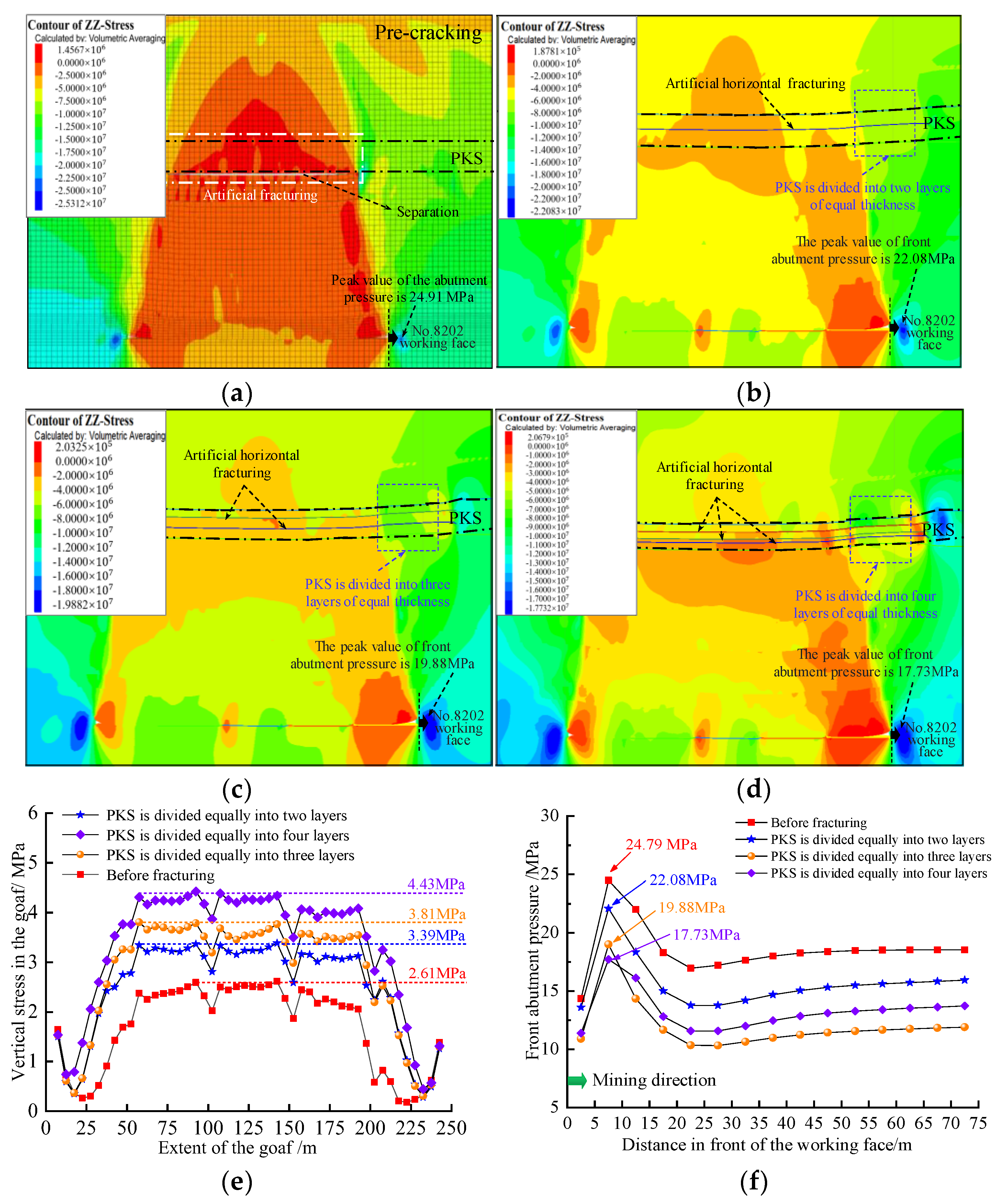
5.2. Horizontal Fractures with Different Layer Thicknesses

Based on those above-mentioned high-level key stratum cutting simulation methods, the high PKS is also cut with different thicknesses of horizontal fractures; the horizontal fracture cutting scheme is shown in Figure 9, in which PKS was divided into two/three/four layers through one/two/three horizontal fracture surfaces. The distribution of the mining-induced stress is shown in Figure 10a–d, respectively, and the corresponding front abutment pressure and goaf stress are shown in Figure 10e,f.
When the PKS is divided into two layers, the width of the stress recovery zone in the goaf area is 211 m, the peak value of goaf stress is 3.39 MPa, and the peak value of front abutment pressure is 22.08 MPa, as shown in Figure 10b,e,f. When the PKS is divided into three layers, the width of the stress recovery zone in the goaf is 213 m, the peak value of goaf stress is 3.81 MPa, and the peak value of the front abutment pressure is 19.88 MPa, as shown in Figure 10c,e,f. When the PKS is divided into four layers, the width of the stress recovery zone in the goaf area is 216 m, the peak value of goaf stress is 4.43 MPa, and the peak value of front abutment pressure is 17.73 MPa, as shown in Figure 10d–f. With the increase in the number of horizontal fracture surfaces, the width of the stress recovery zone in the goaf after fracturing increases, the goaf stress increases, and the peak value of front abutment pressure decreases accordingly. It indicates that the greater the degree of fracturing and fragmentation of the high key stratum, the greater the sinking amount of the high key stratum, which promotes the transfer of the PKS overlying load to the collapse rock mass in the goaf.

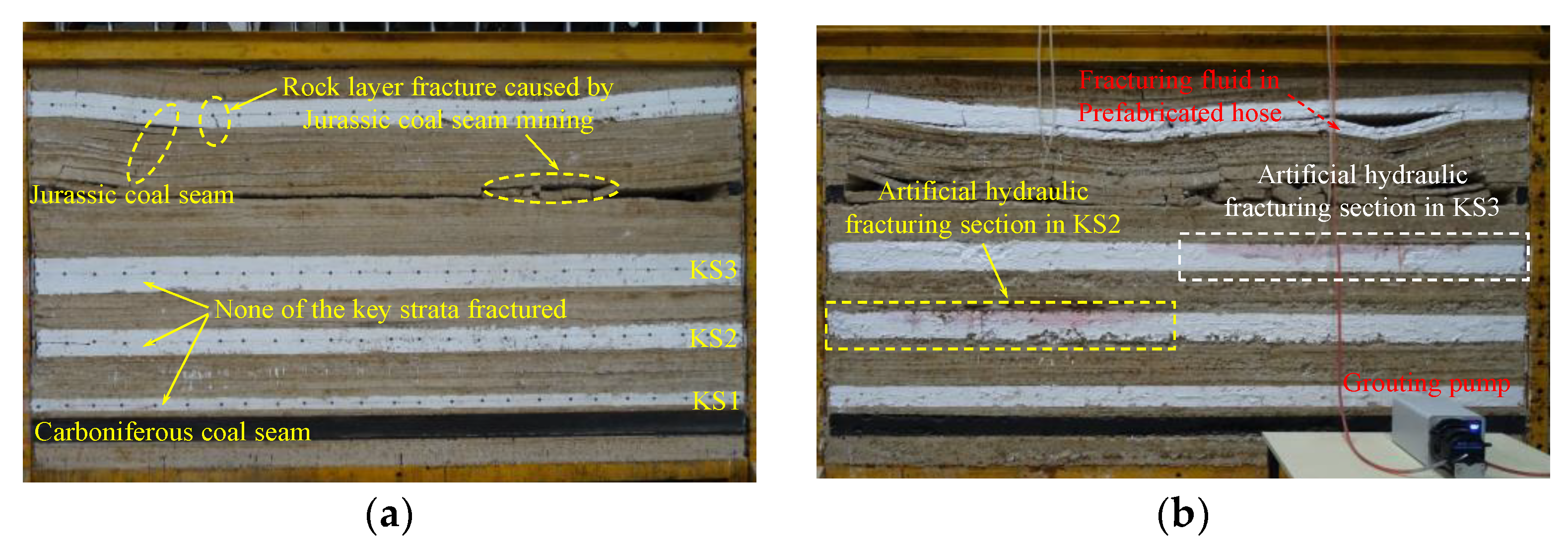
6. Physical Simulation for Weakening Mine Pressure by Key Strata Fracturing

6.1. Physical Simulation Model and Key Strata Fracturing Scheme

Similar simulation studies are carried out according to the similarity simulation theory, and the weakening effect of overlying key strata fracturing on the mine pressure behavior is further explored. Two sets of similar models are produced: the geometric similarity ratio, the density similarity ratio, the stress similarity ratio, and the Poisson’s ratio, which are 1:200, 1:1.60, 1:320, and 1:1, respectively.
Similar simulation experiments mainly use the primary materials of sand, gypsum, calcium carbonate, and water. Different proportions of these materials are mixed and laid in the model frame to simulate the fracture and movement characteristics of the overlying strata above the coal mining face. Based on the above-mentioned rock mechanics test results, a proportioning experiment was conducted on similar simulated materials, and the material proportioning was ultimately obtained, as shown in Table 2.
Model 1 is a control group in which the key strata are not fractured, as shown in Figure 11a. Model 2 is the experimental group in which the key strata will be fractured before mining, and an embedded hose with holes is placed in KS2 and KS3 in the production process. Red water is injected into KS2 and KS3 through the grouting pump through the small hole on the hose, which can simulate the weakening effect of the key strata, as shown in Figure 11b,c. During this process, the flow rate of the injected water is constant to realize the weakening effect on the material parameters of the key stratum. On this basis, the thin film stress distributed sensor monitors the goaf stress after the overlying strata collapse. The stress test film size is 6 cm × 6 cm, the size of a single measurement point microelement is about 1.5 mm × 1.5 mm, and the distribution density of stress test points is 36/cm2. The range of a single stress measurement point microelement is 1000 Pa, and 1600 stress measurement points are integrated with a test film, as shown in Figure 11d. The weakening effect of key strata fracturing on mine pressure behavior is analyzed by comparing the fracture characteristics of key strata and the goaf stress in models 1 and 2.

6.2. Comparative Analysis of Test Results

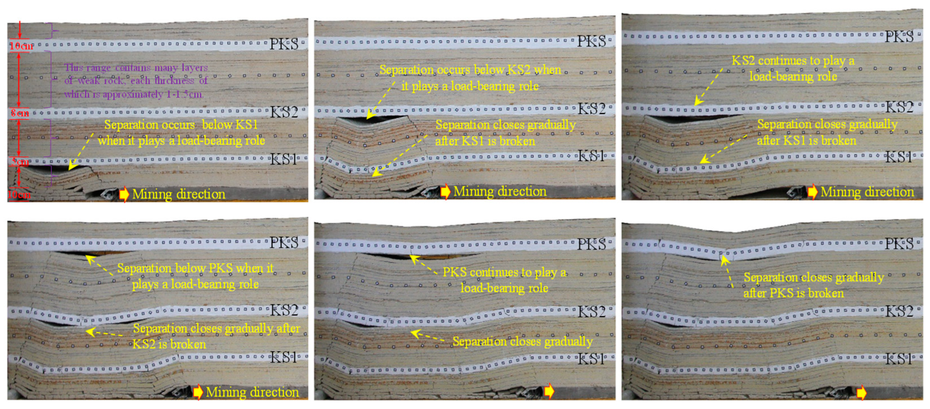
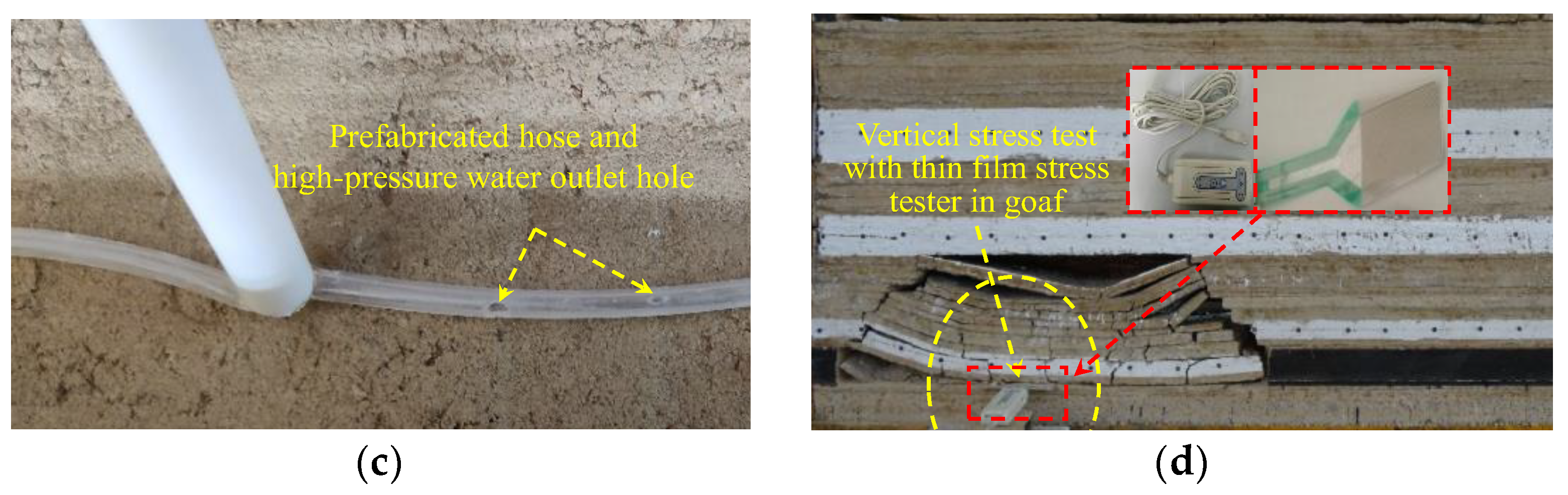
6.2.1. Influence of Hydraulic Fracturing on the Breaking Step of Key Strata

During the excavation process, the Jurassic coal seam was first mined, and then KS2 and KS3 were fractured in model 2, while model 1 did not perform water-injection fracturing on the key strata. Finally, the carboniferous coal seam is excavated. The strata breakage and movement of these two models are shown in Figure 12. In model 1, when the working face advances to 112.6 cm, KS1 undergoes the first break. When the working face goes to 171.6 cm, KS2 and KS3 experience the first break, and the maximum overhang length of both is 135.8 cm and 106.3 cm, respectively, as shown in Figure 12a,c. In model 2, KS1 undergoes the first break when the working face advances to 90.32 cm, and KS2 and KS3 break when the working face advances to 131.6 cm, with a maximum overhang length of 104.8 cm and 93.5 cm, as shown in Figure 12b,d. It can be seen that after fracturing, the bearing capacity of the key strata is significantly reduced, and the maximum overhang span length and breaking step are reduced considerably. This valuable physical simulation has also been used in the literature to prove the influence of key strata fracturing on the fracture characteristics [50].

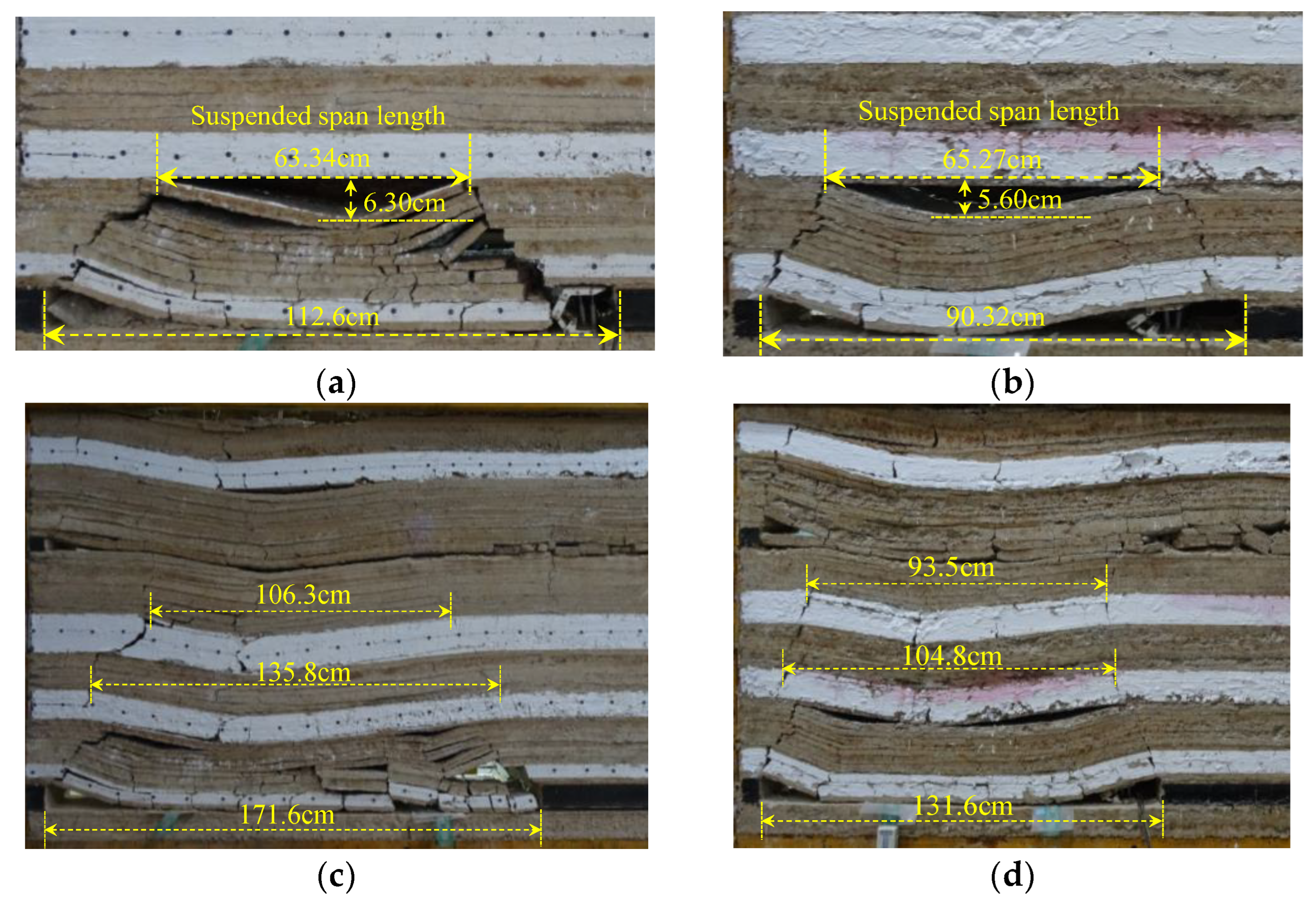
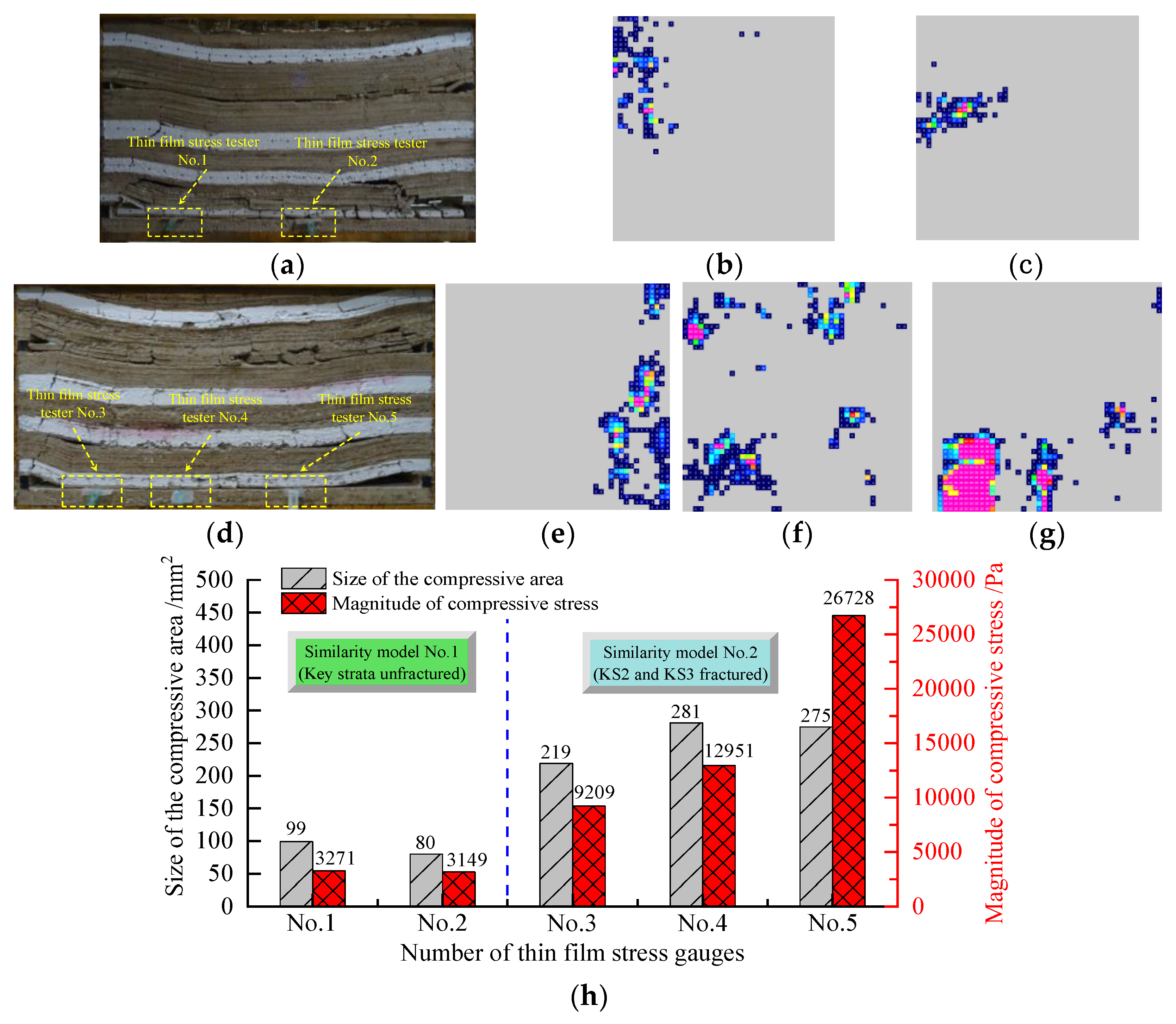
6.2.2. Influence of Hydraulic Fracturing on Goaf Stress

The strata movement results of the two models are shown in Figure 13, and the goaf stress is extracted according to the thin film stress gauge. The results show that in model 1 without hydraulic fracturing, the total number of stress measurement points with data is 99 in thin film stress gauge No. 1, as shown in Figure 13b, the total compressive area is about 222.75 mm2, and the combined pressure value is 3271 Pa. The total number of stress measurement points with data is 80 in thin film stress gauge No. 2, as shown in Figure 13c. The total compressive area is about 180 mm2, and the combined pressure value is 3149 Pa. In the fractured model 2, the total number of stress measurement points with data is 219 in thin film stress gauge No. 3, as shown in Figure 13e, the total compressive area is about 492.75 mm2, and the combined pressure value is 9209 Pa. The total number of stress measurement points with data is 281 in thin film stress gauge No. 4, as shown in Figure 13f. The total compressive area is about 632.25 mm2, and the combined pressure value is 12,951 Pa. The total number of stress measurement points with data is 275 in thin film stress gauge No. 5, as shown in Figure 13g. The total compressive area is about 618.75 mm2, and the combined pressure value is 26,728 Pa. It can be seen that the overlying rock layer collapses more fully after the key strata are fractured; the overlying load is transferred more to the collapsed rock in the goaf area, which is consistent with the above-mentioned numerical simulation results.

7. Engineering Practices

Given the problem of controlling the strong mine pressure behavior of the No. 8202 working face, ground hydraulic fracturing on high-level key stratum is carried out, as shown in Figure 14a. At the middle of the No. 8202 working face, the fracturing well is drilled vertically downward from the surface to the fracturing high-level key stratum. The drilling hole is first drilled from the surface to a stable bedrock section of 10 m by a Φ311 mm drill bit, which is followed by a Φ244.5 mm × 8.94 mm casing, a Φ215.9 mm drill bit drilled to the end, and a Φ139.7 mm × 7.72 mm casing. The first perforation and fracturing are carried out in the high key stratum with a total thickness of 39.15 m. Multiple small holes are first perforated in the entire thickness of the PKS so that the fracturing fluid can expand through the small holes to achieve fracturing. Fracturing is mainly divided into two steps as follows. Firstly, the initial fracturing is carried out by 50 m3 acid; the acid composition is 12% HCl + 5% HF. The acid solution’s strata dissolution reduces the rock’s mechanical properties and promotes the splitting and propagation of the high-pressure acid in the fracture. Secondly, nearly 510.0 m3 of water containing about 10 m3 of quartz sand with a particle size range of 0.225~0.45 mm is used to fracture the key strata further, which has a vital role in enhancing the fracturing effect, effectively supporting the crack propagation and preventing the crack from closing. The resistance of the hydraulic support of the No. 8202 working face and No. 8203 working face are shown in Figure 14b, respectively. It can be seen that the front abutment pressure of the No. 8202 is significantly smaller than that of the adjacent No. 8203 working face with the high key stratum unfractured. This engineering practice, which has also been mentioned in the literature [51], has provided substantial proof that key strata fracturing can effectively weaken the mine pressure behavior.

8. Conclusions

(1) The mechanism of weakening mine pressure behavior after the fracturing of key strata is revealed. After the key strata are cracked, the separation space below the key strata is closed, and the key strata are in contact with the fallen rock mass below, transferring overburden load to the collapsed rock mass in the goaf. This is the main reason why the goaf stress increases and the abutment pressure decreases after the key strata are fractured, which also reasonably explains the phenomenon that the degree of strong mine pressure in the working face can be reduced after the key layer is fractured.
(2) Numerical and physical simulations on the fracturing of key strata to weaken mine pressure are carried out. After the vertical crack fracturing of the key strata, the lead abutment pressure of the working face can be significantly reduced, and the vertical stress in the goaf can be increased. Compared with the lead abutment pressure of 24.91 MPa and the goaf stress of 2.61 MPa when the key strata were not fractured, the peak abutment pressure was reduced to 20.60 MPa, 17.80 MPa and 16.13 MPa when the vertical crack spacing was 20 m, 15 m and 10 m, respectively. In comparison, the stress in the goaf increased to 3.54 MPa, 3.91 MPa and 4.34 MPa, respectively. At the same time, the key strata are also fractured into two horizontal layers, three horizontal layers, and four horizontal layers with horizontal fractures. The peak abutment pressure decreased from 24.79 to 22.08 MPa, 19.88 MPa, and 17.73 MPa, respectively, while the goaf stress increased from 2.61 to 3.39 MPa, 3.81 MPa and 4.43 MPa, respectively. Fracturing the key strata promotes the transfer of overlying load to the goaf, leading to the increase in goaf stress and decrease in abutment pressure, which was verified by physical simulation.
(3) Field engineering practices for weakening mine pressure behavior through key strata fracturing are conducted. The results show that compared to the adjacent No. 8203 working face, where key strata are not fractured, the pressure of the hydraulic support in the No. 8202 working face is significantly reduced, and the intensity of mine pressure behavior is greatly alleviated, effectively ensuring the safe mining of the No.8202 working face.

Author Contributions

Conceptualization, Z.L. and R.G.; methodology, C.Q.; software, Z.L.; validation, Z.L., C.Q. and R.G.; formal analysis, C.Q.; investigation, Z.L.; resources, Z.L.; data curation, C.Q.; writing—original draft preparation, B.Y.; writing—review and editing, Y.Z.; visualization, C.Q.; supervision, H.Z.; project administration, J.Z.; funding acquisition, Z.L. All authors have read and agreed to the published version of the manuscript.

Funding

This research was funded by the Natural Science Research General Program for Shanxi Provincial Basic Research Program (grant number: 202303021211060), Joint Funds of the National Natural Science Foundation of China (grant number: U22A20169), and National Natural Science Foundation of China (grant number: 52274135).

Institutional Review Board Statement

Not applicable for studies not involving humans or animals.

Informed Consent Statement

Not applicable.

Data Availability Statement

Data are contained within the article.

Acknowledgments

The authors thank the editor and reviewers for evaluating the article and providing valuable suggestions and guidance.

Conflicts of Interest

The authors declare no conflicts of interest.

References

  1. Balat, M. Status of Fossil Energy Resources: A Global Perspective. Energy Source Part B 2007, 2, 31–47. [Google Scholar] [CrossRef]
  2. Wu, X.F.; Chen, G.Q. Coal Use Embodied in Globalized World Economy: From Source to Sink Through Supply Chain. Renew. Sustain. Energy Rev. 2018, 81, 978–993. [Google Scholar] [CrossRef]
  3. Liu, C.; Li, H.M.; Mitri, H. Effect of Strata Conditions on Shield Pressure and Surface Subsidence at a Longwall Top Coal Caving Working Face. Rock Mech. Rock Eng. 2019, 52, 1523–1537. [Google Scholar] [CrossRef]
  4. Xu, C.; Fu, Q.; Cui, X.Y.; Wang, K.; Zhao, Y.X.; Cai, Y.B. Apparent-Depth Effects of the Dynamic Failure of Thick Hard Rock Strata on the Underlying Coal Mass During Underground Mining. Rock Mech. Rock Eng. 2019, 52, 1565–1576. [Google Scholar] [CrossRef]
  5. Xu, B.; Jiang, J.Q.; Dai, J.; Zheng, P.Q. Mechanical Derivation and Experimental Simulation of Breaking Angle of Key Strata in Overlying Strata. J. China Coal Soc. 2018, 43, 599–606. (In Chinese) [Google Scholar]
  6. Zhu, W.B.; Yu, B. Breakage Form and Its Effect on Strata Behavior of Far Field Key Stratum in Large Space Stope. Coal Sci. Technol. 2018, 46, 99–104. (In Chinese) [Google Scholar]
  7. Jiang, J.Q.; Zhang, P.P.; Qin, G.P.; Xu, B. Analysis of Destabilized Fracture and Microseismic Activity of High-located Main Key Strata. Rock Soil Mech. 2015, 36, 3567–3575. (In Chinese) [Google Scholar]
  8. Jiang, J.Q.; Zhang, P.P.; Qin, G.P.; Li, F.C.; Xu, B.; Xu, L.N. Fracture Laws of One-side Mined High-position Hard Thick Key Strata and Microseismic Energy Distribution. J. Min. Saf. Eng. 2015, 32, 523–529. (In Chinese) [Google Scholar]
  9. Yu, B.; Gao, R.; Xia, B.W.; Kuang, T.J. Ground Fracturing Technology and Application of Hard Roof in Large Space. J. China Coal Soc. 2021, 46, 800–811. (In Chinese) [Google Scholar]
  10. Li, Z.; Xu, J.L.; Ju, J.F.; Zhu, W.B.; Xu, J.M. The Effects of the Rotational Speed of Voussoir Beam Structures Formed by Key Strata on the Ground Pressure of Stopes. Int. J. Rock Mech. Min. Sci. 2018, 108, 67–79. [Google Scholar] [CrossRef]
  11. Li, Z.; Yu, S.C.; Zhu, W.B.; Feng, G.R.; Xu, J.M.; Guo, Y.X.; Qi, T.Y. Dynamic Loading Induced by the Instability of Voussoir Beam Structure During Mining Below the Slope. Int. J. Rock Mech. Min. Sci. 2020, 132, 104343. [Google Scholar] [CrossRef]
  12. Kuang, T.J.; Li, Z.; Zhu, W.B.; Xie, J.L.; Ju, J.F.; Liu, J.R.; Xu, J.M. The Impact of Key Strata Movement on Ground Pressure Behaviour in the Datong Coalfield. Int. J. Rock Mech. Min. Sci. 2019, 119, 193–204. [Google Scholar] [CrossRef]
  13. Li, Z.; Zhang, H.; Jiang, Z.; Feng, G.R.; Cui, J.Q.; Ma, J.K. Research on Failure Criteria and Collapse Height of Roadway Roof Strata Based on Energy Accumulation and Dissipation Characteristics. Energy Sci. Eng. 2021, 9, 2461–2473. [Google Scholar] [CrossRef]
  14. Gao, R.; Kuang, T.J.; Meng, X.B.; Huo, B.J. Effects of Ground Fracturing with Horizontal Fracture Plane on Rock Breakage Characteristics and Mine Pressure Control. Rock Mech. Rock Eng. 2021, 54, 3229–3243. [Google Scholar] [CrossRef]
  15. Yu, B.; Gao, R.; Kuang, T.J.; Huo, B.J.; Meng, X.B. Engineering Study on Fracturing High-level Hard Rock Strata by Ground Hydraulic Action. Tunn. Undergr. Space Technol. 2019, 86, 156–164. [Google Scholar] [CrossRef]
  16. Wang, F.; Xu, J.L.; Xie, J.L. Effects of Arch Structure in Unconsolidated Layers on Fracture and Failure of Overlying Strata. Int. J. Rock Mech. Min. Sci. 2019, 114, 141–152. [Google Scholar] [CrossRef]
  17. Ji, S.T.; He, H.; Karlovsek, J. Application of Superposition Method to Study the Mechanical Behaviour of Overlying Strata in Longwall Mining. Int. J. Rock Mech. Min. Sci. 2021, 146, 104874. [Google Scholar] [CrossRef]
  18. Hu, C.S.; Apel, D.; Sudak, L.J.; Liu, W.V.; Chu, Z.Y. Physical Investigation on the Behaviours of Voussoir Beams. J. Rock Mech. Geotech. Eng. 2020, 12, 516–527. [Google Scholar] [CrossRef]
  19. Newman, D.; Hutchinson, A.J.; Mason, D.P. Tensile Fracture Analysis of a Thin Euler-Bernoulli Beam and the Transition to the Voussoir Model. Int. J. Rock Mech. Min. Sci. 2018, 102, 78–88. [Google Scholar] [CrossRef]
  20. Ran, Q.C.; Liang, Y.P.; Zou, Q.L.; Hong, Y.; Zhang, B.C.; Liu, H.; Kong, F.J. Experimental Investigation on Mechanical Characteristics of Red Sandstone Under Graded Cyclic Loading and Its Inspirations for Stability of Overlying Strata. Geomech. Geophys. Geo-Energy Geo-Resour. 2023, 9, 11. [Google Scholar] [CrossRef]
  21. Jiang, L.S.; Wu, Q.S.; Wu, Q.L.; Wang, P.; Xue, Y.C.; Kong, P.; Gong, B. Fracture Failure Analysis of Hard and Thick Key Layer and its Dynamic Response Characteristics. Eng. Fail. Anal. 2019, 98, 118–130. [Google Scholar] [CrossRef]
  22. Yang, S.; Wang, J.; Li, X.H.; Ning, J.G.; Qiu, P.Q. In Situ Investigations into Mining-induced Hard Main Roof Fracture in Longwall Mining: A Case Study. Eng. Fail. Anal. 2019, 106, 14. [Google Scholar] [CrossRef]
  23. Ning, J.G.; Wang, J.; Jiang, L.S.; Jiang, N.; Liu, X.S.; Jiang, J.Q. Fracture Analysis of Double-layer Hard and Thick Roof and the Controlling Effect on Strata Behavior: A Case Study. Eng. Fail. Anal. 2017, 81, 117–134. [Google Scholar] [CrossRef]
  24. Yu, M.L.; Zuo, J.P.; Sun, Y.J.; Mi, C.N.; Li, Z.D. Investigation on Fracture Models and Ground Pressure Distribution of Thick Hard Rock Strata Including Weak Interlayer. Int. J. Min. Sci. Technol. 2022, 32, 137–153. [Google Scholar] [CrossRef]
  25. Ju, Y.; Wang, Y.L.; Su, C.S.; Zhang, D.S.; Ren, Z.Y. Numerical Analysis of the Dynamic Evolution of Mining-induced Stresses and Fractures in Multilayered Rock Strata Using Continuum-based Discrete Element Methods. Int. J. Rock Mech. Min. Sci. 2019, 113, 191–210. [Google Scholar] [CrossRef]
  26. Liu, J.W.; Liu, C.Y.; Yao, Q.L.; Si, G.Y. The Position of Hydraulic Fracturing to Initiate Vertical Fractures in Hard Hanging Roof for Stress Relief. Int. J. Rock Mech. Min. Sci. 2020, 132, 13. [Google Scholar] [CrossRef]
  27. Chen, J.C.; Qu, Z.Z.; Zhou, L.; Su, X.P. Numerical Study on the Hydraulic Fracturing Pattern in the Hard Roof in Response to Mining-Induced Stress. Minerals 2023, 13, 308. [Google Scholar] [CrossRef]
  28. Lu, Y.Y.; Gong, T.; Xia, B.W.; Yu, B.; Huang, F. Target Stratum Determination of Surface Hydraulic Fracturing for Far-Field Hard Roof Control in Underground Extra-Thick Coal Extraction: A Case Study. Rock Mech. Rock Eng. 2019, 52, 2725–2740. [Google Scholar] [CrossRef]
  29. Wang, W.; Cheng, Y.P.; Wang, H.F.; Liu, H.Y.; Wang, L.; Li, W.; Jiang, J.Y. Fracture Failure Analysis of Hard-thick Sandstone Roof and its Controlling Effect on Gas Emission in Underground Ultra-thick Coal Extraction. Eng. Fail. Anal. 2015, 54, 150–162. [Google Scholar] [CrossRef]
  30. Shang, X.G.; Zhu, S.T.; Jiang, F.X.; Liu, J.H.; Li, J.J.; Hitch, M.; Liu, H.L.; Tang, S.B.; Zhu, C. Study on Dynamic Disaster Mechanisms of Thick Hard Roof Induced by Hydraulic Fracturing in Surface Vertical Well. Minerals 2022, 12, 1537. [Google Scholar] [CrossRef]
  31. Jia, Y.Z.; Lu, Z.H.; Liu, H.; Wang, J.H.; Cheng, Y.G.; Zhang, X.W. Fracture Propagation and Morphology Due to Non-Aqueous Fracturing: Competing Roles between Fluid Characteristics and In Situ Stress State. Minerals 2020, 10, 428. [Google Scholar] [CrossRef]
  32. Jameei, A.A.; Pietruszczak, S. On Hydromechanical Interaction during Propagation of Localized Damage in Rocks. Minerals 2021, 11, 162. [Google Scholar] [CrossRef]
  33. Gong, X.; Ma, X.H.; Liu, Y.Y.; Li, G.F. Advances in Hydraulic Fracture Propagation Research in Shale Reservoirs. Minerals 2022, 12, 1438. [Google Scholar] [CrossRef]
  34. Munoz-Ibanez, A.; Herbon-Penabad, M.; Delgado-Martin, J.; Alejano-Monge, L.; Alvarellos-Iglesias, J.; Canal-Vila, J. Hydrostatic, Strike-slip and Normal Stress True Triaxial Hydrofracturing Testing of Blanco Mera Granite: Breakdown Pressure and Tensile Strength Assessment. Geomech. Geophys. Geo-Energy Geo-Resour. 2023, 9, 31. [Google Scholar] [CrossRef]
  35. Saber, E.; Qu, Q.D.; Sarmadivaleh, M.; Aminossadati, S.M.; Chen, Z.W. Propagation of Multiple Hydraulic Fractures in a Transversely Isotropic Shale Formation. Int. J. Rock Mech. Min. Sci. 2023, 170, 105010. [Google Scholar] [CrossRef]
  36. Pham, C.; Zhuang, L.; Yeom, S.; Shin, H.S. Automatic Fracture Characterization in CT Images of Rocks Using an Ensemble Deep Learning Approach. Int. J. Rock Mech. Min. Sci. 2023, 170, 105531. [Google Scholar] [CrossRef]
  37. Abousleiman, R.; Sinha, S.; Walton, G. Analysis of the Historic Bondi Pumping Chamber Case Study Using the Adjusted Voussoir Beam Analog. Rock Mech. Rock Eng. 2023, 56, 6357–6374. [Google Scholar] [CrossRef]
  38. Yiouta-Mitra, P.; Sofianos, A.I. Multi-jointed Stratified Hard Rock Roof Analysis and Design. Int. J. Rock Mech. Min. Sci. 2018, 106, 96–108. [Google Scholar] [CrossRef]
  39. Shabanimashcool, M.; Li, C.C. Analytical Approaches for Studying the Stability of Laminated Roof Strata. Int. J. Rock Mech. Min. Sci. 2015, 79, 99–108. [Google Scholar] [CrossRef]
  40. Hadei, M.R.; Veiskarami, A. An Experimental Investigation of Hydraulic Fracturing of Stratified Rocks. Bull. Eng. Geol. Environ. 2021, 80, 491–506. [Google Scholar] [CrossRef]
  41. Szurgacz, D.; Brodny, J. Analysis of the Influence of Dynamic Load on the Work Parameters of a Powered Roof Support’s Hydraulic Leg. Sustainability 2019, 11, 2570. [Google Scholar] [CrossRef]
  42. Xuan, D.Y.; Wang, B.L.; Xu, J.L. A Shared Borehole Approach for Coal-bed Methane Drainage and Ground Stabilization with Grouting. Int. J. Rock Mech. Min. Sci. 2016, 86, 235–244. [Google Scholar] [CrossRef]
  43. Ju, J.F.; Xu, J.L. Surface Stepped Subsidence Related to Top-coal Caving Longwall Mining of Extremely Thick Coal Seam Under Shallow Cover. Rock Mech. Rock Eng. 2015, 78, 27–35. [Google Scholar] [CrossRef]
  44. Qu, Q.D.; Guo, H.; Khanal, M. Monitoring and Analysis of Ground Movement from Multi-seam Mining. Int. J. Rock Mech. Min. Sci. 2021, 148, 104949. [Google Scholar] [CrossRef]
  45. Maqsood, Z.; Koseki, J.; Ahsan, M.K.; Shaikh, M.; Kyokawa, H. Experimental study on hardening characteristics and loading rate dependent mechanical behavior of gypsum mixed sand. Constr. Build. Mater. 2020, 262, 119992. [Google Scholar] [CrossRef]
  46. Mahanta, B.; Singh, T.N.; Ranjith, P.G.; Vishal, V. Experimental investigation of the influence of strain rate on strength; failure attributes and mechanism of Jhiri shale. J. Nat. Gas Sci. Eng. 2018, 58, 178–188. [Google Scholar] [CrossRef]
  47. Maqsood, Z.; Koseki, J.; Miyashita, Y.; Xie, J.; Kyokawa, H. Experimental study on the mechanical behavior of bounded geomaterials under creep and cyclic loading considering effects of instantaneous strain rates. Eng. Geol. 2020, 276, 105774. [Google Scholar] [CrossRef]
  48. Wang, H.S.; Wang, J.; Elmo, D.; He, M.C.; Ma, Z.M.; Gao, C.Z. Ground response mechanism of entries and control methods induced by hard roof in longwall top coal caving panel. Eng. Fail. Anal. 2023, 144, 21. [Google Scholar] [CrossRef]
  49. Gao, R.; Yang, J.X.; Kuang, T.J.; Liu, H.J. Investigation on the Ground Pressure Induced by Hard Roof Fracturing at Different Layers during Extra Thick Coal Seam Mining. Geofluids 2020, 2020, 8834235. [Google Scholar] [CrossRef]
  50. Mondal, D.; Roy, P.N.S.; Kumar, M. Monitoring the strata behavior in the Destressed Zone of a shallow Indian longwall panel with hard sandstone cover using Mine-Microseismicity and Borehole Televiewer data. Eng. Geol. 2020, 271, 25. [Google Scholar] [CrossRef]
  51. Gao, R.; Yu, B.; Meng, X.B. Study on the Mechanism of Strong Strata Behavior Influenced by Overlying Coal Pillar and Control Technology of Ground Fracturing. J. Min. Saf. Eng. 2018, 35, 324–331. (In Chinese) [Google Scholar]
Figure 1. A realistic view of the strong mine pressure and geographical location of No. 8202 working face. (a) Location of Datong Mining Area; (b) strata columnar of No. 8202 working face; (c) support crushed, hydraulic prop topple and floor heave in roadway.
Applsci 14 00415 g001
Figure 2. Breakage and movement of key strata in overlying strata.
Applsci 14 00415 g002
Figure 3. Influence of fracturing PKS on overburden load transfer and mining-induced stress distribution. (a) Load transfer path before PKS break; (b) load transfer path after PKS fractured.
Applsci 14 00415 g003
Figure 4. Numerical simulation method for KS fracturing. (a) Node opening and separation; (b) contact surface node fusion principle.
Applsci 14 00415 g004
Figure 5. FLAC3D numerical simulation model and calibration of numerical simulation parameters of No. 8202 working face. (a) Simulation model; (b) calibration of numerical simulation.
Applsci 14 00415 g005
Figure 6. Front abutment pressure and goaf stress with different advancing distances. (a) 50 m; (b) 100 m; (c) 150 m; (d) 200 m; (e) 250 m; (f) 300 m.
Applsci 14 00415 g006
Figure 7. Schematic diagram of vertical fracture fracturing with different spacing in PKS. (a) Fracturing spacing 10 m; (b) fracturing spacing 15 m; (c) fracturing spacing 20 m.
Applsci 14 00415 g007
Figure 8. Cloud and curve diagrams of vertical stress with different vertical fracture spacing in the PKS. (a) PKS has not been fractured yet; (b) fracturing spacing 10 m; (c) fracturing spacing 15 m; (d) fracturing spacing 20 m; (e) vertical stress in goaf; (f) front abutment pressure.
Applsci 14 00415 g008aApplsci 14 00415 g008b
Figure 9. Schematic diagram of horizontal fracture fracturing with different slice thicknesses in PKS. (a) Two layers; (b) three layers; (c) four layers.
Applsci 14 00415 g009
Figure 10. Cloud and curve diagrams of vertical stress with horizontal layering of different thicknesses. (a) PKS has not been fractured yet; (b) horizontal crack cutting with two layers; (c) horizontal crack cutting with three layers; (d) horizontal crack cutting with four layers; (e) vertical stress in goaf; (f) front abutment pressure.
Applsci 14 00415 g010
Figure 11. Test plan and related monitoring instruments. (a) Key strata unfractured; (b) key strata fractured; (c) prefabricated hoses and water injection fracturing; (d) vertical stress test with thin film stress tester in goaf.
Applsci 14 00415 g011aApplsci 14 00415 g011b
Figure 12. Influence of water injection fracturing on the breaking of key strata. (a) First break of KS1 in model 1; (b) first break of KS1 in model 2; (c) first break of KS2 and KS3 in model 1; (d) first break of KS2 and KS3 in model 2.
Applsci 14 00415 g012
Figure 13. Influence of water injection fracturing on the stress in goaf. (a) Thin film stress tester in model 1; (b) vertical stress of thin film stress tester No. 1; (c) vertical stress of thin film stress tester No. 2; (d) thin film stress tester in model 2; (e) vertical stress of thin film stress tester No. 3; (f) vertical stress of thin film stress tester No. 4; (g) vertical stress of thin film stress tester No. 5; (h) comparative analysis of vertical stress in goaf before and after key strata fracturing.
Applsci 14 00415 g013
Figure 14. Fracturing practice and weakening effect of mine pressure appearance. (a) Field engineering; (b) comparison of mine pressure.
Applsci 14 00415 g014
Table 1. Numerical simulation of rock formation mechanical parameters.
No.NameElastic Modulus
E/GPa
Compressive Strength
σc/MPa
Tensile Strength
σt /MPa
Poisson’s Ratio
μ
Cohesion
C/MPa
Internal Friction Angle
f/°
1Coarse sandstone2336.833.90.244.122
2Medium sandstone19.538.63.70.255.123
3Siltstone18.523.532.60.274.222
4Fine sandstone6090.4312.40.218.425
5Siltstone19.127.634.20.226.123
6Coal seam7.516.131.10.323.920
7Mudstone5.725.42.30.273.821
8Carbonaceous mudstone1315.421.40.223.721
9Sandy mudstone10.532.22.80.275.222
Table 2. Mixture ratio of similar material of each stratum.
No.NameSand (kg)CaCO3 (kg)Gypsum (kg)
1Coarse sandstone23.285.432.33
2Medium sandstone9.100.461.06
3Siltstone26.252.630.90
4Fine sandstone14.350.862.63
5Siltstone23.632.362.36
6Coal seam21.002.700.30
7Mudstone17.682.471.06
8Carbonaceous mudstone9.701.360.58
9Sandy mudstone20.683.562.15
Disclaimer/Publisher’s Note: The statements, opinions and data contained in all publications are solely those of the individual author(s) and contributor(s) and not of MDPI and/or the editor(s). MDPI and/or the editor(s) disclaim responsibility for any injury to people or property resulting from any ideas, methods, instructions or products referred to in the content.

