


RTMN 2.0—An Extension of Robot Task Modeling and Notation (RTMN) Focused on Human–Robot Collaboration


Abstract
:1. Introduction
1.1. What Is Human–Robot Collaboration (HRC)?
1.2. The Importance of Human–Robot Collaboration (HRC)
1.3. Safety Standards and HRC Modes
- Safety-rated monitored stop (SMS)
- Hand-guiding (HG)
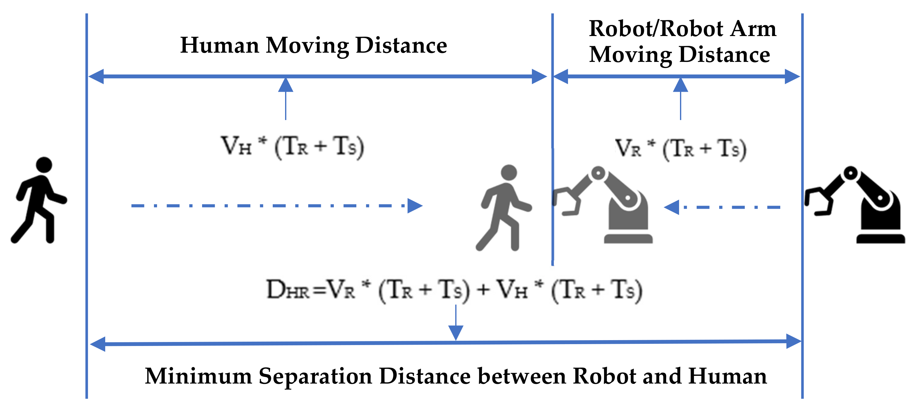
- Speed and separation monitoring (SSM)
- Power and force limiting (PFL)
1.4. HRC Task Types
2. Materials and Methods
2.1. Literature Review and Analysis on HRC Modeling Methods
2.1.1. Business Process Modeling Notation (BPMN)
2.1.2. Unified Modeling Language (UML)
2.1.3. Systems Modeling Language (SysML)
2.1.4. Behavior Trees
2.1.5. Petri Nets
2.1.6. Research Gap
2.2. RTMN 2.0—Extension of RTMN
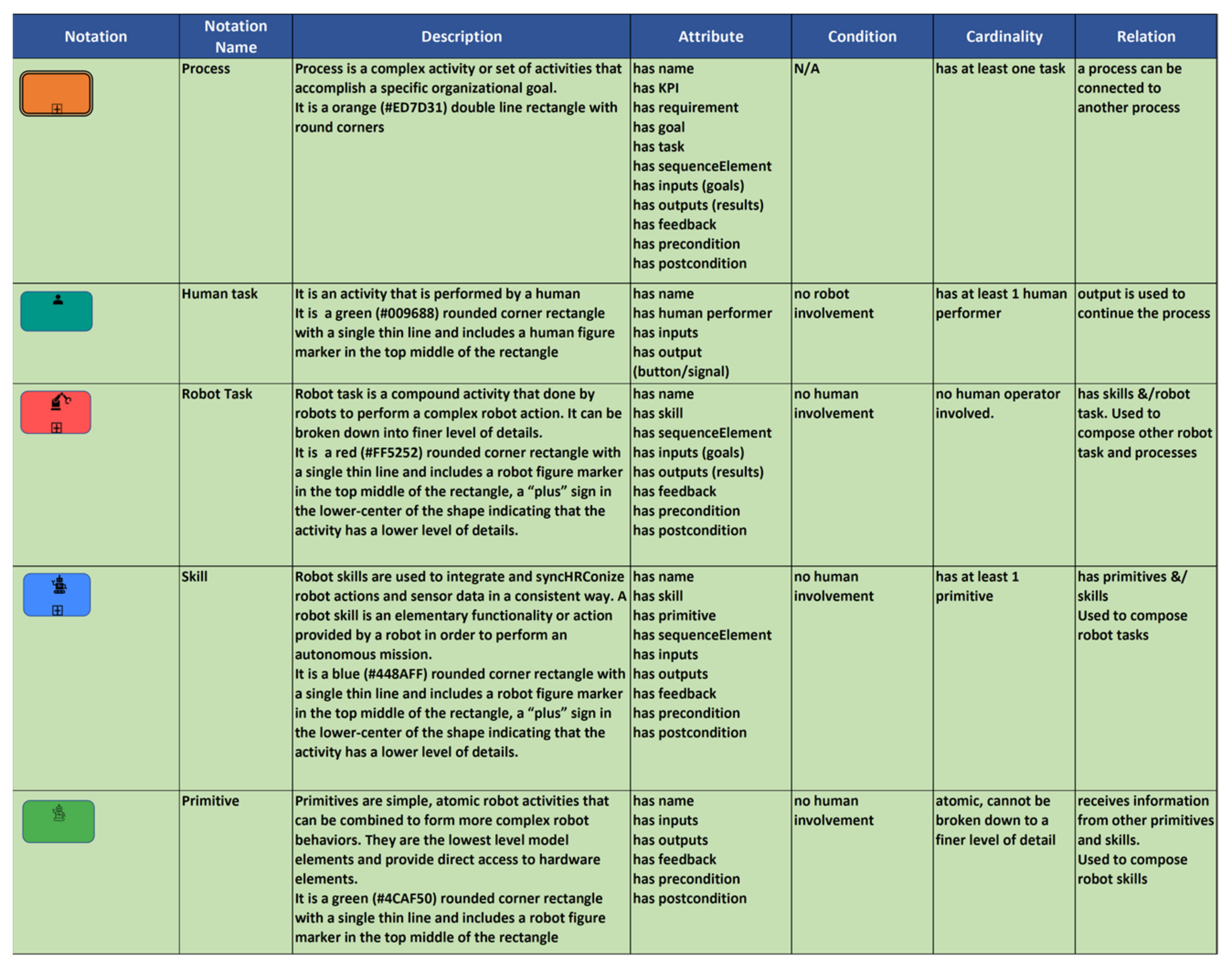
2.2.1. The RTMN Elements
2.2.2. The RTMN 2.0 Elements
- Adding HRC modeling elements, including safety in combination with collaboration modes and task types of humans and robots. This has significantly enriched the former RTMN model and enabled it to be applied to HRC application areas.
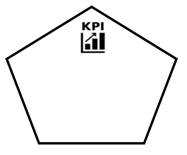
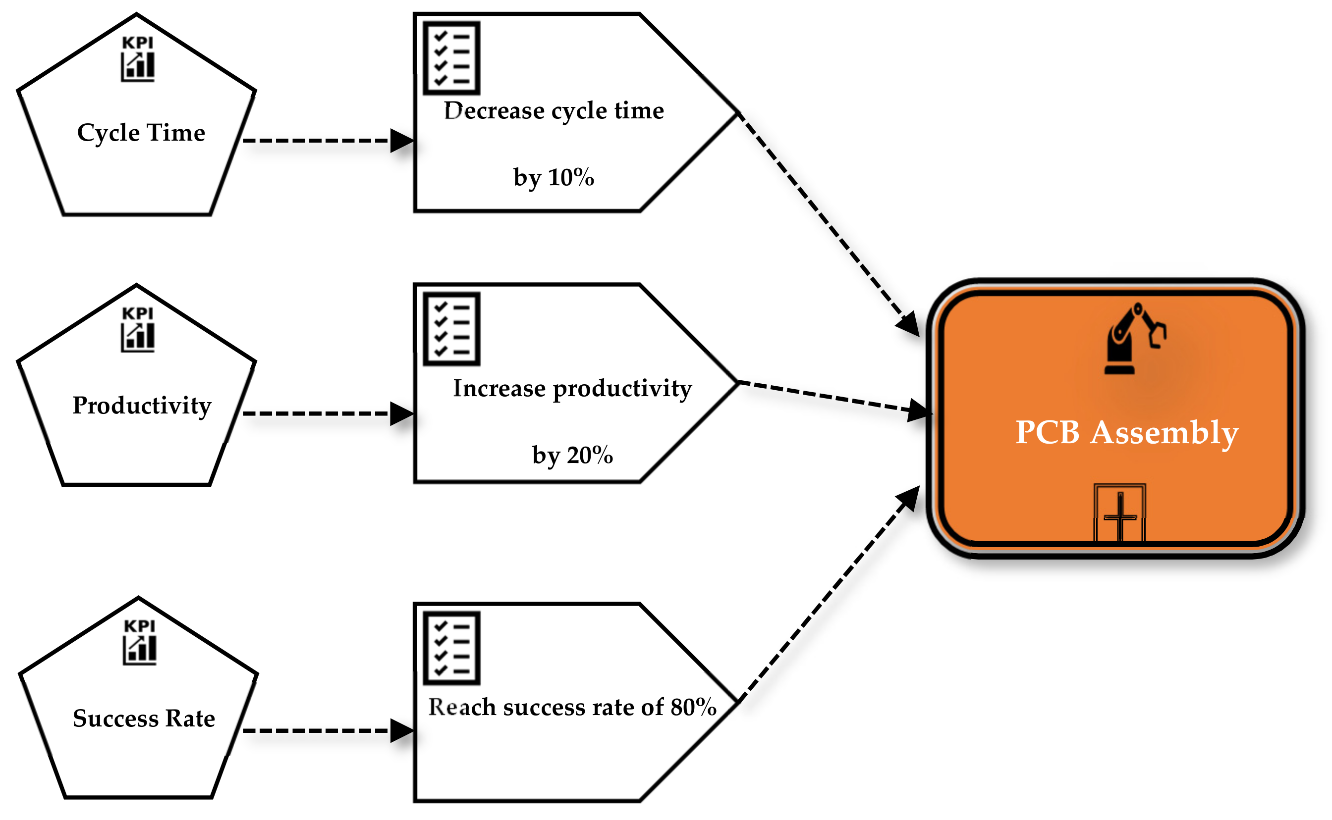
- Adding requirements, with KPI as a basic element.
- Adding the link from requirements/KPI to robot control.
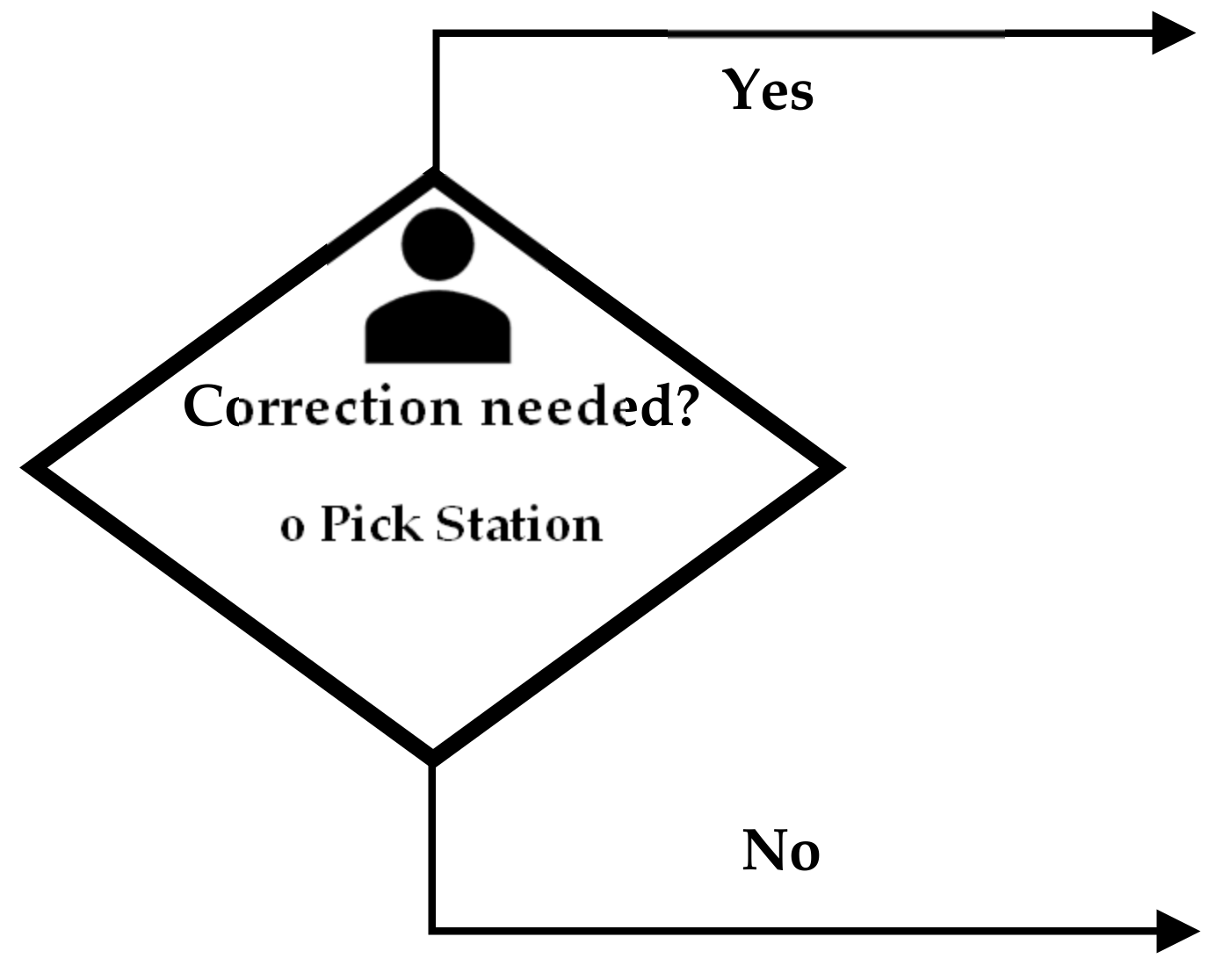
- Adding decision-making elements.
2.2.3. The RTMN 2.0 Sequence Flow Connection Rules
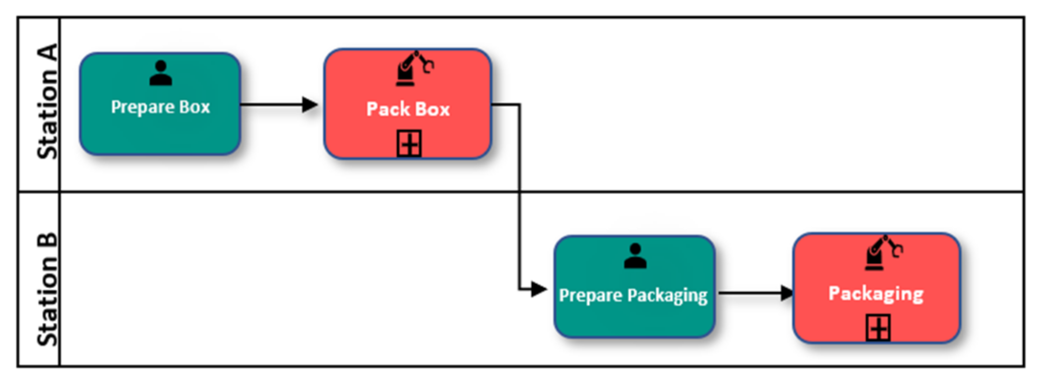
2.2.4. The HRC Model
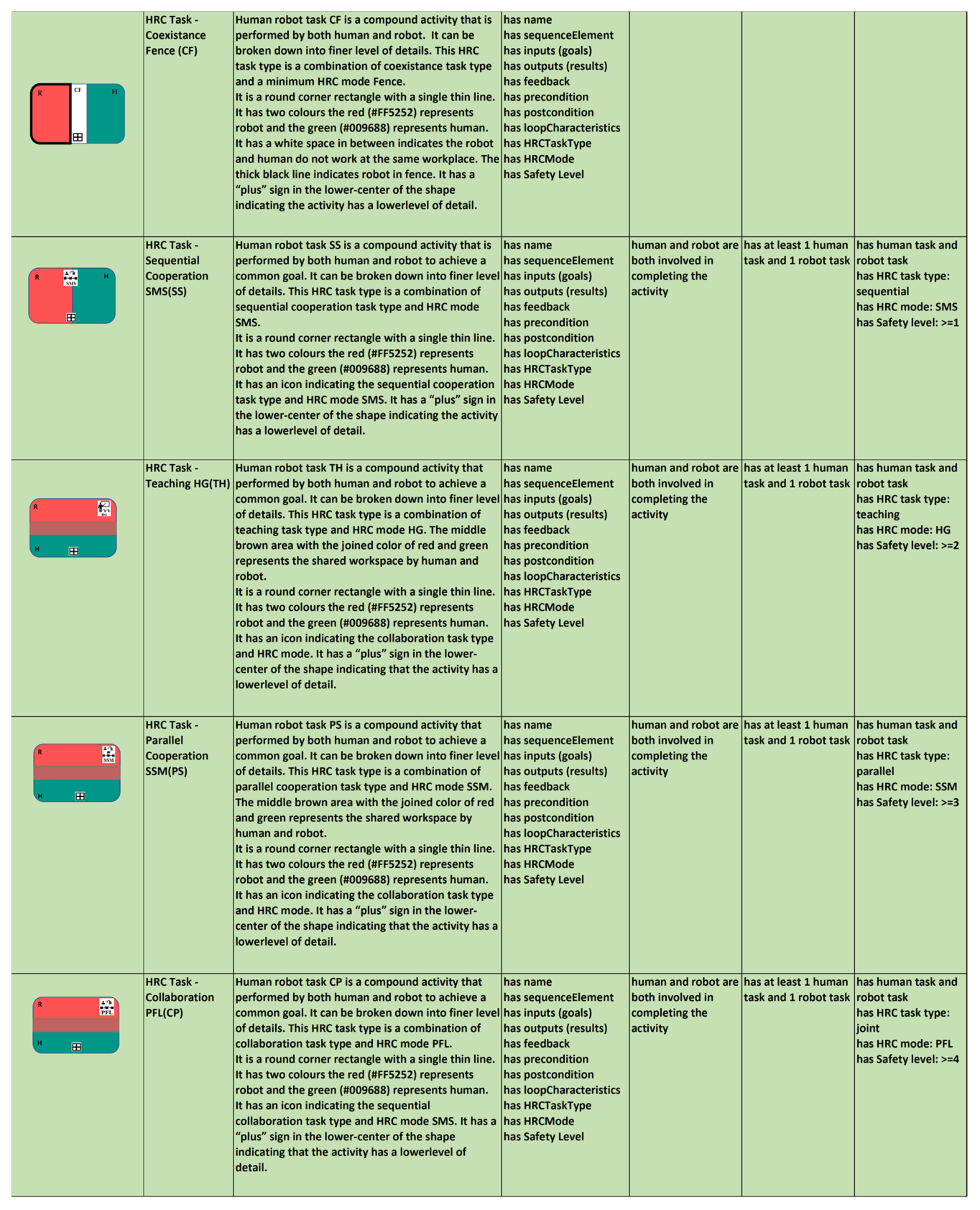
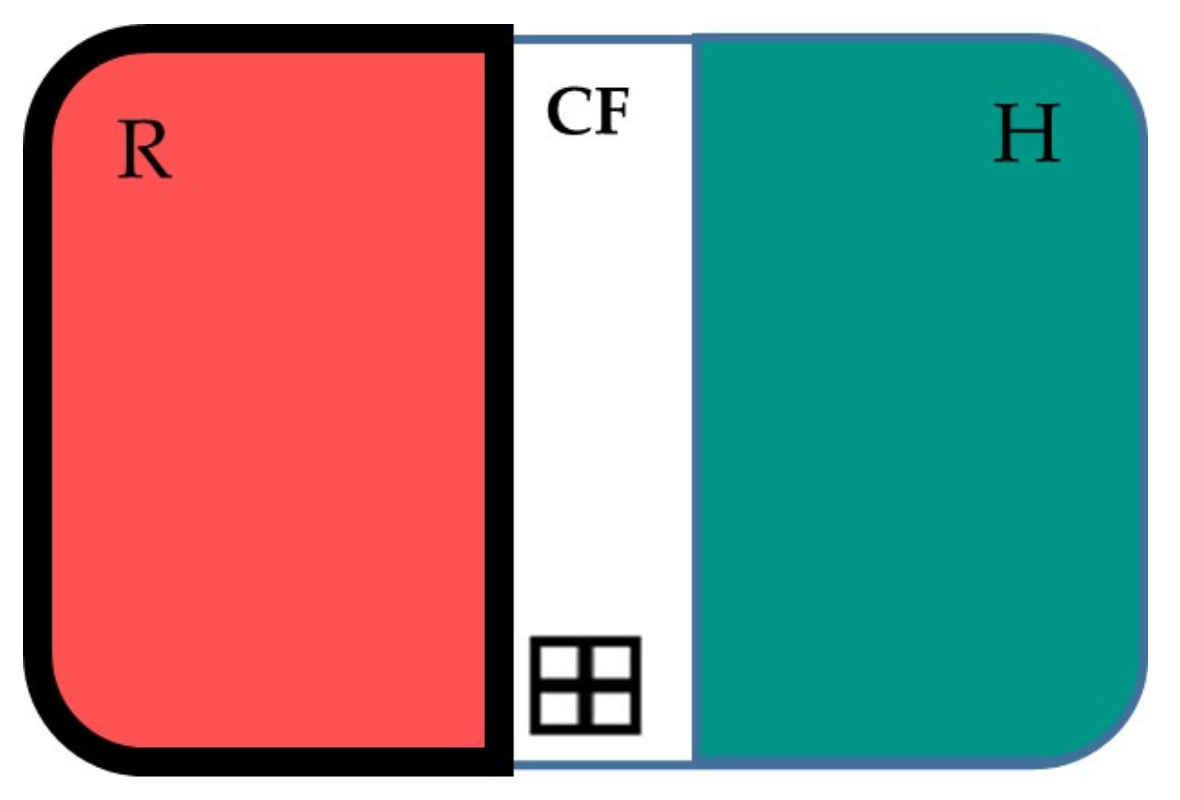
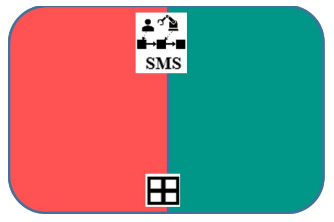
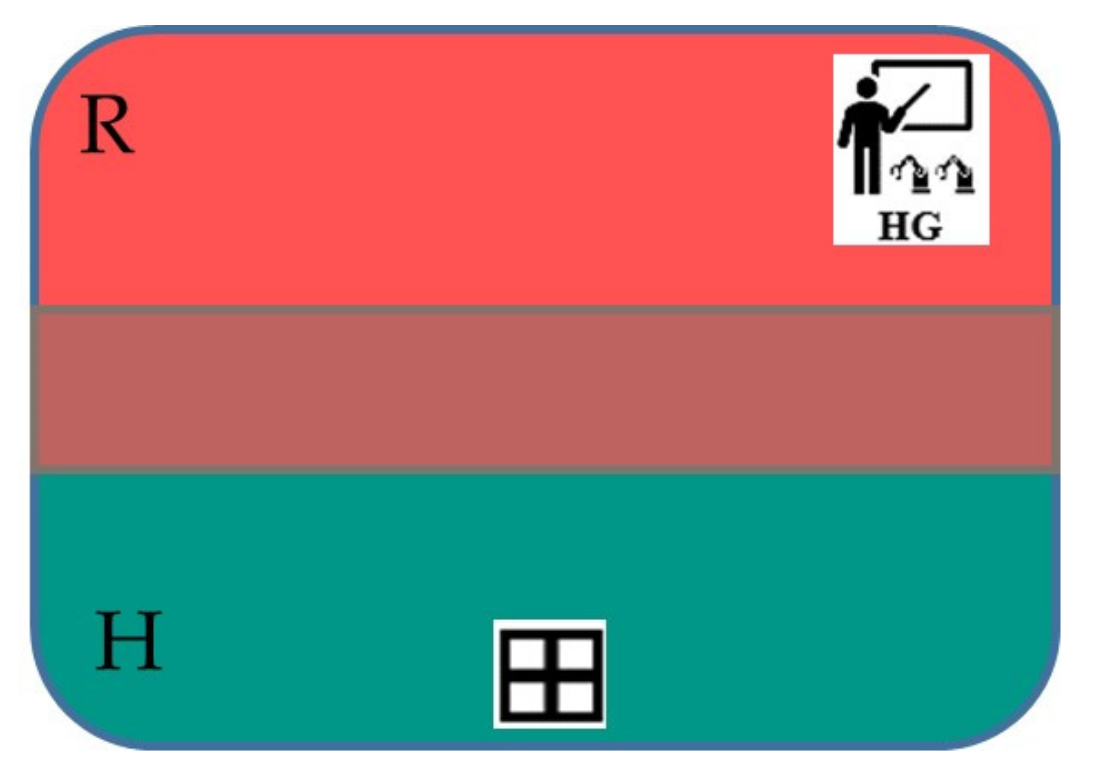
Combining Collaboration Task Types and HRC Modes
- Coexistence Fence (CF)
- Sequential Cooperation SMS (SS)
- Teaching HG (TH)
- Parallel Cooperation SSM (PS)
- Collaboration PFL (CP)
Workspace
Decision Making
2.2.5. Other Extensions and Modifications
Requirements and KPI
Traceability of Requirements and KPIs
Robotic Process
Skill and Primitive
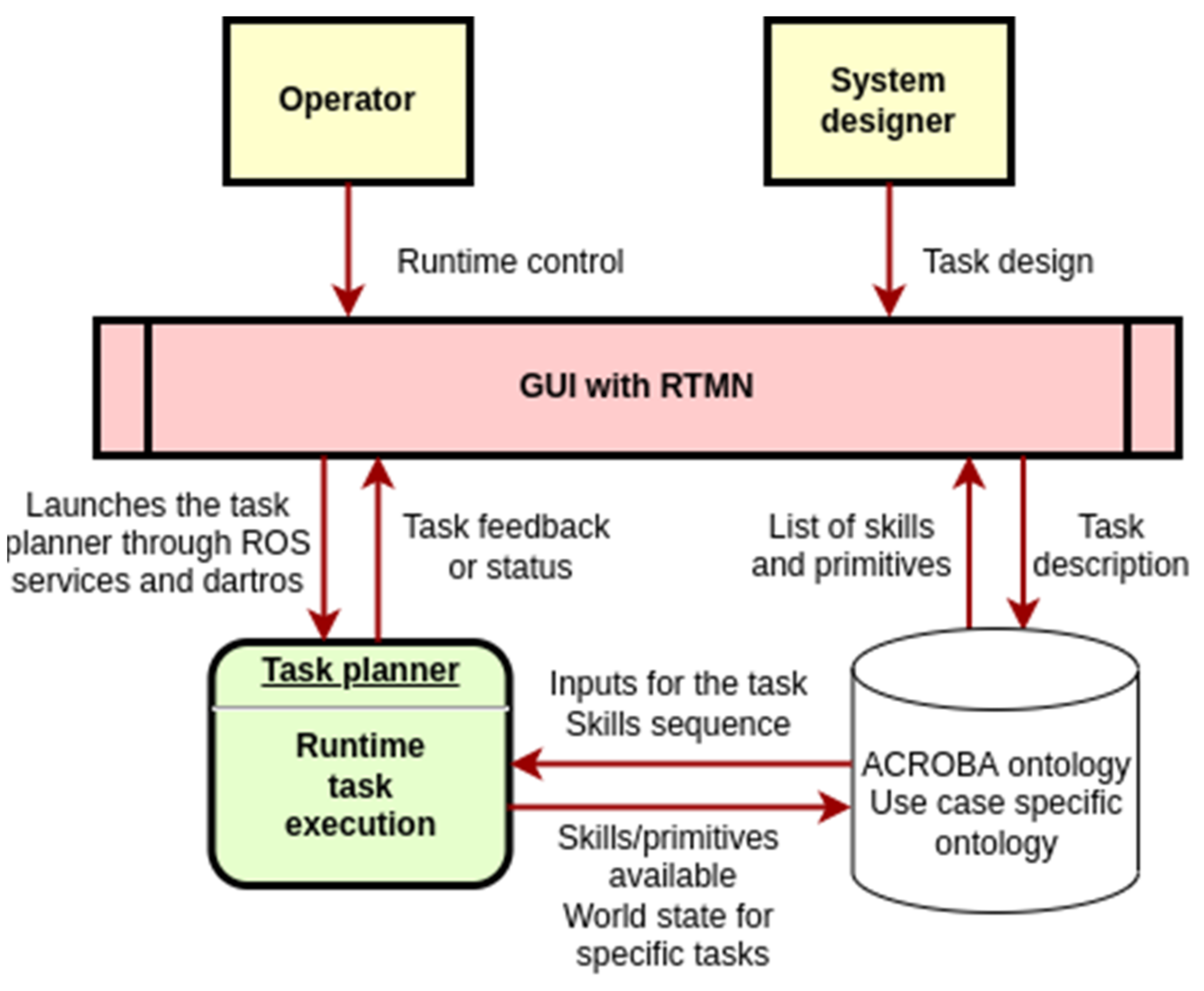
2.2.6. The Implementation
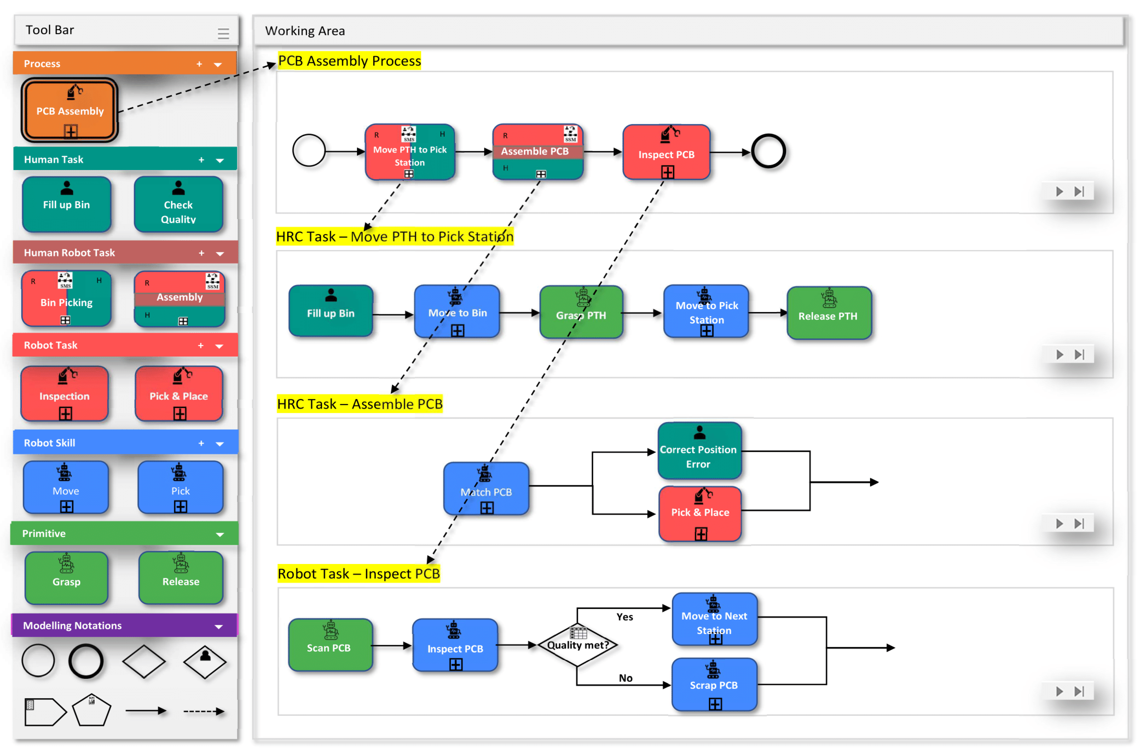
2.2.7. Demonstration
3. Results
3.1. Requirement Survey Findings
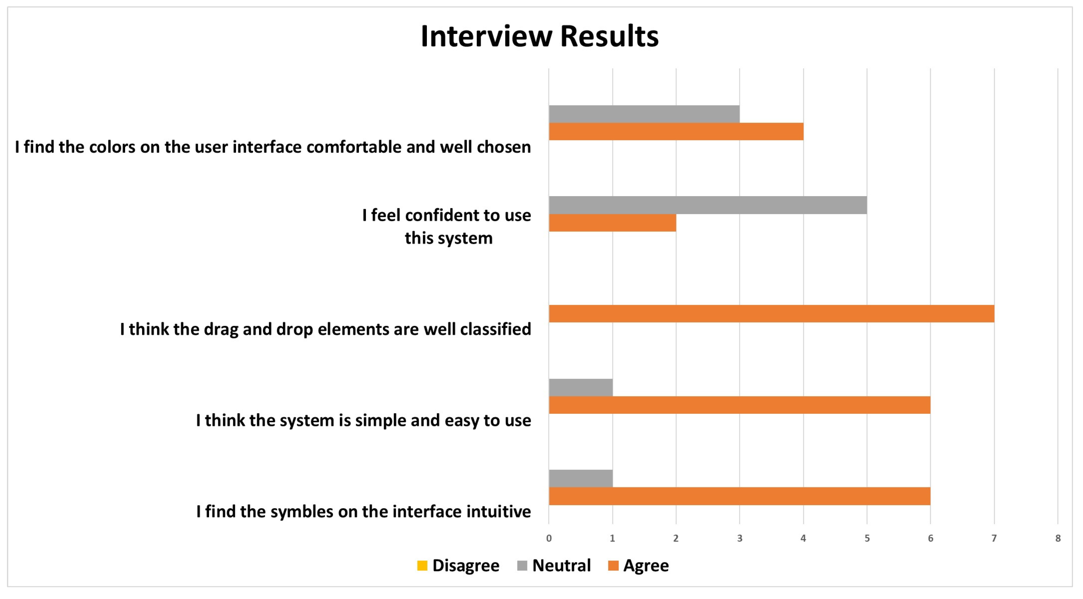
3.2. Early Validation Interview and Survey Findings
4. Discussion
5. Conclusions
Author Contributions
Funding
Institutional Review Board Statement
Informed Consent Statement
Data Availability Statement
Acknowledgments
Conflicts of Interest
Appendix A. Questionnaire for ACROBA User Interface (Plain Version, Link to Google form: https://forms.gle/6iyfGuF2giEUWMWX7)
- What are the users of the ACROBA platform (allow multiple choice)?
- Business users
- Engineers
- Programmers
- Manager
- Others: ___________________
- Do the users want to interact with the system?
- Yes
- No
- Only when error occurs.
- Others: ___________________
- On what device do you expect to manage the control of the robot?
- Smartphone/tablet
- Laptop/PC
- HMI
- Others: __________________
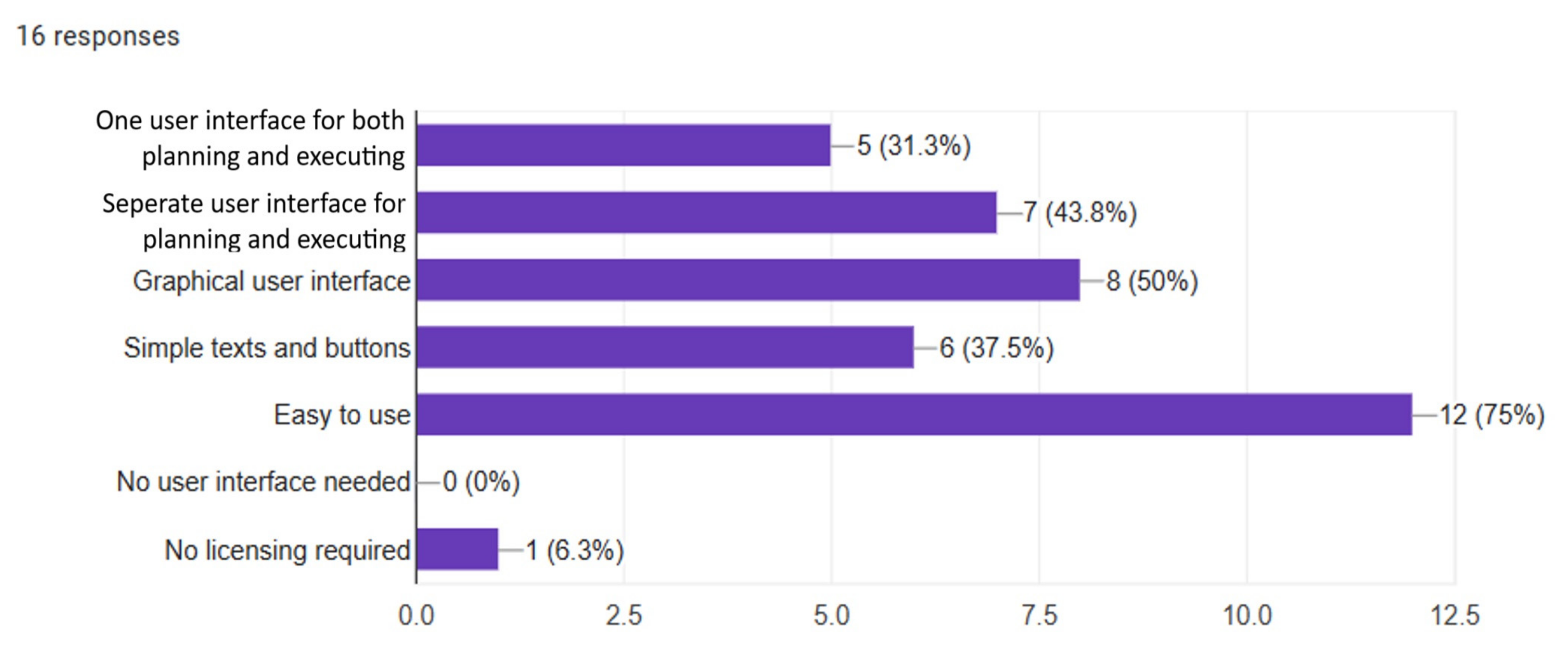
- What do you expect for a user interface of ACROBA?
- One user interface for both planning and execution
- Separate user interface for planning and execution
- Graphical user interface
- Simple texts and buttons
- Easy to use.
- No user interface needed.
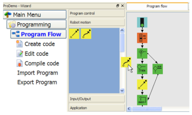
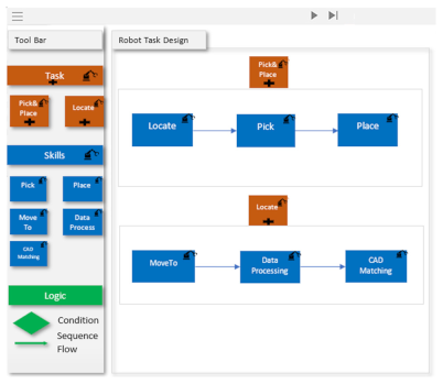
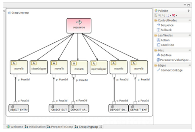
- Which of the following task representations do you like the most?
![Applsci 14 00283 i001]() Source: https://www.researchgate.net/figure/sual-Programming-using-Drag-and-Drop-to-assemble-the-program-flow_fig6_226029194, accessed on 12 November 2023.
Source: https://www.researchgate.net/figure/sual-Programming-using-Drag-and-Drop-to-assemble-the-program-flow_fig6_226029194, accessed on 12 November 2023.![Applsci 14 00283 i002]() Source: https://home.makewonder.com/apps/blockly, accessed on 12 November 2023.
Source: https://home.makewonder.com/apps/blockly, accessed on 12 November 2023.![Applsci 14 00283 i003]() Source: RTMN
Source: RTMN![Applsci 14 00283 i004]() Scheme 12. November 2023.
Scheme 12. November 2023.
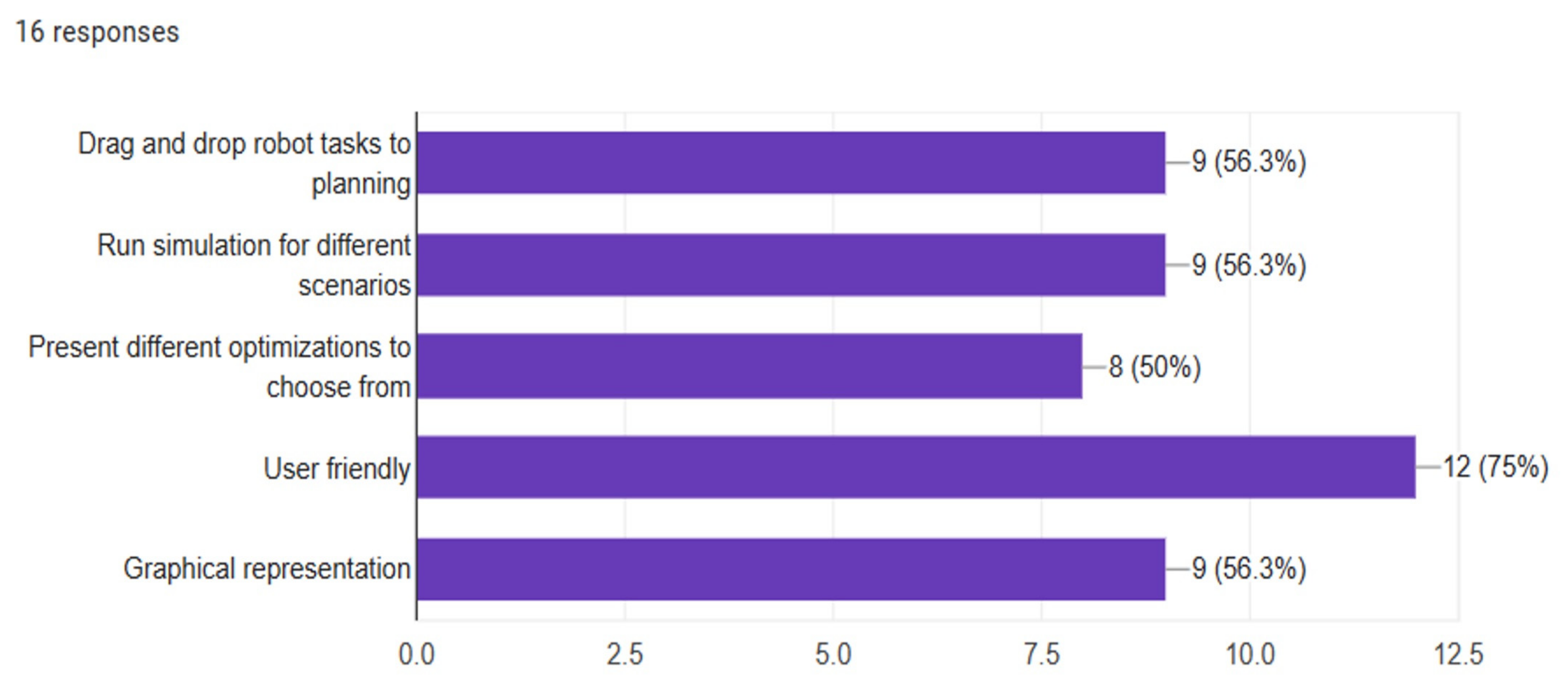
- What do you expect from a user interface for planning robot tasks?
- Drag and drop robot tasks to planning.
- Run simulation for different scenarios.
- Present different optimizations to choose from
- User friendly
- Graphical representation
- Others: ___________________
- What do you expect from a user interface when executing robot tasks?
- An overview of the task execution
- Control the robot tasks execution: _____________________
- go forward.
- backward
- stop
- repeat
- run optimization.
- Others: ___________________
- Provide additional information from different systems when error occurs.
- Information from the Vision system
- Information from the safety system
- Information from robot task
- Others: ___________________
- What do you want to control robot tasks execution?
- go forward.
- go backward
- stop
- repeat
- run optimization.
- Others: ___________________
- What information do you want to see when error occurs?
- Information from the Vision system
- Information from the safety system
- Information from robot task
- Others: ___________________
- Do you have experience working with Robot in the production line?
- Yes
- No
- If yes, what are the problems you have working with robots?
- When there is an error, it is hard to fix the error.
- Error/warning are too technical, not enough information of the system, cannot fix the problem easily.
- Cannot control the robot tasks freely.
- Reprogramming a robot task is very time consuming.
- No overview of the process
- Lacking information from the vision system or other systems of the tasks performed
- User interface is too simple.
- The user interface is not user friendly.
- Others: ___________________

References
- Project—Acroba Project. Available online: https://acrobaproject.eu/project-acroba/ (accessed on 28 February 2022).
- Sprenger, C.Z.; Ribeaud, T. Robotic Process Automation with Ontology-Enabled Skill-Based Robot Task Model and Notation (RTMN). In Proceedings of the 2nd International Conference on Robotics, Automation and Artificial Intelligence (RAAI), Singapore, 9–11 December 2022; pp. 15–20. [Google Scholar] [CrossRef]
- BPMN Specification—Business Process Model and Notation. Available online: https://www.bpmn.org/ (accessed on 27 February 2022).
- Li, Y.; Ge, S.S. Human-Robot Collaboration Based on Motion Intention Estimation. IEEE/ASME Trans. Mechatron. 2014, 19, 1007–1014. [Google Scholar] [CrossRef]
- Weiss, A.; Wortmeier, A.K.; Kubicek, B. Cobots in Industry 4.0: A Roadmap for Future Practice Studies on Human-Robot Collaboration. IEEE Trans. Hum. Mach. Syst. 2021, 51, 335–345. [Google Scholar] [CrossRef]
- Lubold, N.; Walker, E.; Pon-Barry, H. Effects of voice-adaptation and social dialogue on perceptions of a robotic learning companion. In Proceedings of the HRI’16: The 11th ACM/IEEE International Conference on Human Robot Interation, Christchurch, NZ, USA, 7–10 March 2016. [Google Scholar]
- Institute of Electrical and Electronics Engineers. A Special Project of the IEEE Region 3 Strategic Planning Committee; IEEE: Piscataway, NJ, USA, 2015. [Google Scholar]
- Freedy, A.; DeVisser, E.; Weltman, G.; Coeyman, N. Measurement of Trust in Human-Robot Collaboration. In Proceedings of the International Symposium on Collaborative Technologies and Systems, Orlando, FL, USA, 25 May 2007. [Google Scholar]
- IEEE Staff. Proceedings of the IEEE/RSJ International Conference on Intelligent Robots and Systems; IEEE: Piscataway, NJ, USA, 2010. [Google Scholar]
- Kumar, S.; Savur, C.; Sahin, F. Survey of Human-Robot Collaboration in Industrial Settings: Awareness, Intelligence, and Compliance. IEEE Trans. Syst. Man. Cybern. Syst. 2021, 51, 280–297. [Google Scholar] [CrossRef]
- Kock, S.; Vittor, T.; Matthias, B.; Jerregard, H.; Källman, M.; Lundberg, I.; Hedelind, M. Robot concept for scalable, flexible assembly automation: A technology study on a harmless dual-armed robot. In Proceedings of the IEEE International Symposium on Assembly and Manufacturing, Tampere, Finland, 25–27 May 2011. [Google Scholar]
- Matheson, E.; Minto, R.; Zampieri, E.G.G.; Faccio, M.; Rosati, G. Human–Robot Collaboration in Manufacturing Applications: A Review. Robotics 2019, 8, 100. [Google Scholar] [CrossRef]
- Villani, V.; Pini, F.; Leali, F.; Secchi, C. Survey on Human-Robot Collaboration in Industrial Settings: Safety, Intuitive Interfaces and Applications. Mechatronics 2018, 55, 248–266. [Google Scholar] [CrossRef]
- Kim, A. A Shortage of Skilled Workers Threatens Manufacturing’s Rebound. Available online: https://www.ge.com/news/reports/a-shortage-of-skilled-workers-threatens-manufacturings-r (accessed on 23 October 2023).
- Vysocky, A.; Novak, P. Human—Robot Collaboration in Industry. MM Sci. J. 2016, 903–906. [Google Scholar] [CrossRef]
- International Federation of Robotics. Available online: https://ifr.org/ (accessed on 18 July 2023).
- ISO 12100:2010; Safety of Machinery—General Principles for Design—Risk Assessment and Risk Reduction. International Organization for Standardization: Geneva, Switzerland, 2010.
- ISO 13849-1:2023; Safety-Related Parts of Control Systems—Part 1: General Principles for Design. International Organization for Standardization: Geneva, Switzerland, 2023.
- ISO 13850:2015; Safety of Machinery—Emergency Stop Function—Principles for Design. International Organization for Standardization: Geneva, Switzerland, 2015.
- ISO 13851:2019; Safety of Machinery—Two-Hand Control Devices—Principles for Design and Selection. International Organization for Standardization: Geneva, Switzerland, 2019.
- ISO 10218-1:2011; Robots and Robotic Devices—Safety Requirements for Industrial Robots—Part 1: Robots. International Organization for Standardization: Geneva, Switzerland, 2011.
- ISO 10218-2:2011; Robots and Robotic Devices—Safety Requirements for Industrial Robots—Part 2: Robot Systems and Integration. International Organization for Standardization: Geneva, Switzerland, 2011.
- EC 62061; Safety of Machinery Functional Safety of Safety-Related Electrical, Electronic and Programmable Electronic Control System. International Electrotechnical Commission: London, UK, 2005.
- ISO/TS 15066:2016; Robots and Robotic Devices—Collaborative Robots. International Organization for Standardization: Geneva, Switzerland, 2016.
- Müller, R.; Vette, M.; Geenen, A. Skill-Based Dynamic Task Allocation in Human-Robot-Cooperation with the Example of Welding Application. Procedia Manuf. 2017, 11, 13–21. [Google Scholar] [CrossRef]
- Wang, L.; Gao, R.; Váncza, J.; Krüger, J.; Wang, X.V.; Makris, S.; Chryssolouris, G. Symbiotic Human-Robot Collaborative Assembly. CIRP Ann. 2019, 68, 701–726. [Google Scholar] [CrossRef]
- Thiemermann, S. Direkte Mensch-Roboter-Kooperation in Der Kleinteilemontage Mit Einem SCARA-Roboter. Ph.D. Thesis, University of Stuttgart, Stuttgart, Germany, 2004. [Google Scholar]
- Müller, R.; Vette, M.; Mailahn, O. Process-Oriented Task Assignment for Assembly Processes with Human-Robot Interaction. Procedia CIRP 2016, 44, 210–215. [Google Scholar] [CrossRef]
- Vincent Wang, X.; Kemény, Z.; Váncza, J.; Wang, L. Human-Robot Collaborative Assembly in Cyber-Physical Production: Classification Framework and Implementation. CIRP Ann. 2017, 66, 5–8. [Google Scholar] [CrossRef]
- Krü, J.; Lien, T.K.; Verl, A. Cooperation of Human and Machines in Assembly Lines. CIRP Ann. 2009, 58, 628–646. [Google Scholar] [CrossRef]
- White, S.A. Introduction to BPMN; Ibm Cooperation: New York, NY, USA, 2004. [Google Scholar]
- Lindorfer, R.; Froschauer, R. Towards user-oriented programming of skill-based Automation Systems using a domain-specific Meta-Modeling Approach. In Proceedings of the IEEE 17th International Conference on Industrial Informatics (INDIN), Helsinki, Finland, 22–25 July 2019; pp. 655–660. [Google Scholar] [CrossRef]
- Pantano, M.; Pavlovskyi, Y.; Schulenburg, E.; Traganos, K.; Ahmadi, S.; Regulin, D.; Lee, D.; Saenz, J. Novel Approach Using Risk Analysis Component to Continuously Update Collaborative Robotics Applications in the Smart, Connected Factory Model. Appl. Sci. 2022, 12, 5639. [Google Scholar] [CrossRef]
- Mahulea, C.; Grau, A.; Lo Bello, L. The 24th IEEE International Conference on Emerging Technologies and Factory Automation Held in Zaragoza, Spain [Society News]. IEEE Ind. Electron. Mag. 2019, 13, 127–128. [Google Scholar] [CrossRef]
- Schmidbauer, C.; Schlund, S.; Ionescu, T.B.; Hader, B. Adaptive Task Sharing in Human-Robot Interaction in Assembly. In Proceedings of the IEEE International Conference on Industrial Engineering and Engineering Management, Singapore, 14 December 2020; pp. 546–550. [Google Scholar]
- Guiochet, J. Hazard Analysis of Human-Robot Interactions with HAZOP-UML. Saf. Sci. 2016, 84, 225–237. [Google Scholar] [CrossRef]
- Martin-Guillerez, D.; Guiochet, J.; Powell, D.; Zanon, C. A UML-Based Method for Risk Analysis of Human-Robot Interactions. In Proceedings of the 2nd International Workshop on Software Engineering for Resilient Systems, New York, NY, USA, 15 April 2010; pp. 32–41. [Google Scholar]
- Guiochet, J.; Motet, G.; Baron, C.; Boy, G. Toward a human-centered uml for risk analysis application to a medical robot. In Human Error, Safety and Systems Development; Springer: Berlin/Heidelberg, Germany, 2004; pp. 177–191. [Google Scholar]
- Guiochet, J.; Hoang, Q.A.D.; Kaaniche, M.; Powell, D. Model-based safety analysis of human-robot interactions: The MIRAS walking assistance robot. In Proceedings of the IEEE International Conference on Rehabilitation Robotics (ICORR), Seattle, WA, USA, 24–26 June 2013. [Google Scholar]
- Von Borstel, F.D.; Villa-Medina, J.F.; Gutiérrez, J. Development of Mobile Robots Based on Wireless Robotic Components Using UML and Hierarchical Colored Petri Nets. J. Intell. Robot. Syst. Theory Appl. 2022, 104, 70. [Google Scholar] [CrossRef]
- Carroll, L.; Tondu, B.; Baron, C.; Geffroy, J.C. UML Framework for the Design of Real-Time Robot Controllers; Springer: Berlin/Heidelberg, Germany, 1999. [Google Scholar]
- Verband der Elektrotechnik, E.; Institute of Electrical and Electronics Engineers. Modeling Robot Assembly Tasks in Manufacturing Using SysML. In Proceedings of the 41st International Symposium on Robotics, Munich, Germany, 2–3 June 2014. [Google Scholar]
- Ohara, K.; Takubo, T.; Mae, Y.; Arai, T. SysML-Based Robot System Design for Manipulation Tasks. In Proceedings of the 5th International Conference on the Advanced Mechatronics, Shenzhen, China, 18–21 December 2020. [Google Scholar]
- Candell, R.; Kashef, M.; Liu, Y.; Foufou, S. A SysML Representation of the Wireless Factory Work Cell: Enabling Real-Time Observation and Control by Modeling Significant Architecture, Components, and Information Flows. Int. J. Adv. Manuf. Technol. 2019, 104, 119–140. [Google Scholar] [CrossRef] [PubMed]
- Avram, O.; Baraldo, S.; Valente, A. Generalized Behavior Framework for Mobile Robots Teaming with Humans in Harsh Environments. Front. Robot. AI 2022, 9, 898366. [Google Scholar] [CrossRef] [PubMed]
- Peterson, J.L. Petri Nets*. Comput. Surv. 1977, 9, 223–252. [Google Scholar] [CrossRef]
- Casalino, A.; Zanchettin, A.M.; Piroddi, L.; Rocco, P. Optimal Scheduling of Human-Robot Collaborative Assembly Operations with Time Petri Nets. IEEE Trans. Autom. Sci. Eng. 2019, 18, 70–84. [Google Scholar] [CrossRef]
- Chao, C.; Thomaz, A. Timed Petri Nets for Fluent Turn-Taking over Multimodal Interaction Resources in Human-Robot Collaboration. Int. J. Rob. Res. 2016, 35, 1330–1353. [Google Scholar] [CrossRef]
- Chao, C.; Thomaz, A. Timing in Multimodal Turn-Taking Interactions: Control and Analysis Using Timed Petri Nets. J. Hum. Robot. Interact. 2012, 1, 4–25. [Google Scholar] [CrossRef]
- Institute of Electrical and Electronics Engineers. Proceedings of the ICRA 2014—IEEE International Conference on Robotics and Automation; IEEE: Piscataway, NJ, USA, 2014. [Google Scholar]
- Yagoda, R.E.; Coovert, M.D. How to Work and Play with Robots: An Approach to Modeling Human-Robot Interaction. Comput. Hum. Behav. 2012, 28, 60–68. [Google Scholar] [CrossRef]
- Casalino, A.; Cividini, F.; Zanchettin, A.M.; Piroddi, L.; Rocco, P. Human-Robot Collaborative Assembly: A Use-Case Application; Elsevier B.V.: Amsterdam, The Netherlands, 2018; Volume 51, pp. 194–199. [Google Scholar]
- Völzer, H. An Overview of BPMN 2.0 and Its Potential Use. In Business Process Modeling Notation; Lecture Notes in Business Information Processing; Springer: Berlin/Heidelberg, Germany, 2010; Volume 67, pp. 14–15. [Google Scholar] [CrossRef]
- ISO—International Organization for Standardization. Available online: https://www.iso.org/obp/ui/en/#iso:std:iso:10218:-1:ed-2:v1:en (accessed on 7 November 2023).
- Caiazzo, C.; Nestić, S.; Savković, M. A Systematic Classification of Key Performance Indicators in Human-Robot Collaboration. Lect. Notes Netw. Syst. 2023, 562, 479–489. [Google Scholar]
- Flutter. Available online: https://flutter.dev/ (accessed on 15 August 2022).
- Dartros|Dart Package. Available online: https://pub.dev/packages/dartros (accessed on 15 August 2022).
- ROS: Home. Available online: https://www.ros.org/ (accessed on 28 February 2022).
- Ribeaud, T.; Sprenger, C.Z. Behavior Trees Based Flexible Task Planner Built on ROS2 Framework. In Proceedings of the IEEE International Conference on Emerging Technologies and Factory Automation, ETFA, Stuttgart, Germany, 6–9 September 2022. [Google Scholar] [CrossRef]
- Pang, W.; Gu, W.; Li, H. Ontology-Based Task Planning for Autonomous Unmanned System: Framework and Principle; Journal of Physics: Conference Series; IOP Publishing Ltd.: Bristol, UK, 2022; Volume 2253. [Google Scholar]
- Davis, F.D.; Venkatesh, V. Toward Preprototype User Acceptance Testing of New Information Systems: Implications for Software Project Management. IEEE Trans. Eng. Manag. 2004, 51, 31–46. [Google Scholar] [CrossRef]
- Davis, F.D. Perceived Usefulness, Perceived Ease of Use, and User Acceptance of Information Technology. Manag. Inf. Syst. Q. 1989, 13, 319–339. [Google Scholar] [CrossRef]
- Hancock, P.A.; Billings, D.R.; Schaefer, K.E. Can You Trust Your Robot? Ergon. Des. Q. Hum. Factors Appl. 2011, 19, 24–29. [Google Scholar] [CrossRef]
- Norman, D. The Design of Everyday Thing; Basic Books: New York, NY, USA, 2013. [Google Scholar]
- Wickens, C.D.; Gordon, S.E.; Liu, Y.; Lee, J. An Introduction to Human Factors Engineering; Pearson Prentice Hall: Upper Saddle River, NJ, USA, 2004; Volume 2. [Google Scholar]
- Asaro, P.M. What Should We Want from a Robot Ethic? In Machine Ethics and Robot Ethics; Routledge: London, UK, 2020; pp. 87–94. [Google Scholar]


| Type | Description | Standard |
|---|---|---|
| Type A Standard | Basic safety standards for general requirements | ISO 12100: 2010 “Machine safety, general design principles, risk assessment, and risk reduction” IEC 61508: terminology and methodology [17] |
| Type B Standard | Generic safety standards |
|
| Type C Standard | Safety countermeasures for specific machineryPrioritized over Type A and Type B standards |
|
| Sequence | Parameter | Equation | Value | Action |
|---|---|---|---|---|
| 1 | Bin status | = | Empty | Fill up bin |
| ≠ | Empty | Do nothing | ||
| 2 | Distance, robot and human | = | VR * (TR + TS) + VH * (TR + TS) | Stop robot |
| > | VR * (TR + TS) + VH * (TR + TS) | Robot run at collaborative speed | ||
| 3 | Quality check | = | Accepted | Move product to next station |
| = | Rejected | Move to rejected bin |
| Requirement | Requirement Formula | Name of KPI | KPI Formula |
|---|---|---|---|
| Decrease cycle time by 10% | (Cycle Time old − Cycle time new)/Cycle Time old ≤ 10% | Cycle Time | Cycle Time = Process end time − Process begin time |
| Increase productivity by 20% | (Productivity old − Productivity new)/Productivity old ≥ 20% | Productivity | Units of product/production time (hours) |
| Reach success rate of 80% | Success Rate ≥ 80% | Success Rate | Nr of success action/Nr of total actions |
| Reach reprogramming time of less than 10 min | Reprogramming Time < 10 min | Reprogramming Time | Time finish reconfiguration − Time start reconfiguration |
| Reduce scrap product to less than 5% | Nr of scrap product/Nr of total product ≤ 5% | Scrap Product | The number of products not accepted in quality inspection |
| Increase machinery utilization to more than 75% | Net Machine Utilization ≥ 75% | Net Machine Utilization | Machine run hours per process/process duration |
| Reduce net operator actuation to less than 25% | Net Operator Actuation ≤ 25% | Net Operator Actuation | Human working hours per process/process duration |
| Reduce accident rate to 0 | Accident Rate = 0 | Accident Rate | The number of reportable health and safety incidents per month |
| Increase human safety/reduce exposure to chemicals/danger | 1 − Human exposure to chemical rate ≥ 30% | Human Exposure to Chemicals | Time of human exposure to chemicals/danger/cycle time |
Disclaimer/Publisher’s Note: The statements, opinions and data contained in all publications are solely those of the individual author(s) and contributor(s) and not of MDPI and/or the editor(s). MDPI and/or the editor(s) disclaim responsibility for any injury to people or property resulting from any ideas, methods, instructions or products referred to in the content. |
© 2023 by the authors. Licensee MDPI, Basel, Switzerland. This article is an open access article distributed under the terms and conditions of the Creative Commons Attribution (CC BY) license (https://creativecommons.org/licenses/by/4.0/).
Share and Cite
Zhang Sprenger, C.; Corrales Ramón, J.A.; Baier, N.U. RTMN 2.0—An Extension of Robot Task Modeling and Notation (RTMN) Focused on Human–Robot Collaboration. Appl. Sci. 2024, 14, 283. https://doi.org/10.3390/app14010283
Zhang Sprenger C, Corrales Ramón JA, Baier NU. RTMN 2.0—An Extension of Robot Task Modeling and Notation (RTMN) Focused on Human–Robot Collaboration. Applied Sciences. 2024; 14(1):283. https://doi.org/10.3390/app14010283
Chicago/Turabian StyleZhang Sprenger, Congyu, Juan Antonio Corrales Ramón, and Norman Urs Baier. 2024. "RTMN 2.0—An Extension of Robot Task Modeling and Notation (RTMN) Focused on Human–Robot Collaboration" Applied Sciences 14, no. 1: 283. https://doi.org/10.3390/app14010283
APA StyleZhang Sprenger, C., Corrales Ramón, J. A., & Baier, N. U. (2024). RTMN 2.0—An Extension of Robot Task Modeling and Notation (RTMN) Focused on Human–Robot Collaboration. Applied Sciences, 14(1), 283. https://doi.org/10.3390/app14010283