Article

Research on the Multi-Angle Seismic Spectrum Response Law of Auxiliary Feedwater Electric Pumps

College of Engineering Science and Technology, Shanghai Ocean University, Shanghai 201306, China
*
Author to whom correspondence should be addressed.
Appl. Sci. 2024, 14(1), 28; https://doi.org/10.3390/app14010028
Submission received: 10 November 2023 / Revised: 6 December 2023 / Accepted: 14 December 2023 / Published: 20 December 2023

Abstract

:
The auxiliary feedwater electric pump, which is vital in nuclear power units, demands exceptional seismic reliability. The impact of the seismic excitation direction on the seismic response of the complex auxiliary feedwater electric pump structure remains inadequately understood, thereby introducing uncertainties into seismic analysis and equipment installation procedures. To address this challenge, this study centers on a representative horizontal multi-stage centrifugal pump based on the finite element model and modal analysis. Utilizing the response spectrum method and the square root of the sum of the squares (SRSS) vibration pattern superposition principle, the research comprehensively explores the seismic response characteristics of individual pressure-bearing components and key rotor positions under seismic excitation from various angles. Findings reveal intricate variations in maximum stress and displacement responses for each pressure-bearing component under safe shutdown earthquake (SSE) level seismic excitation, corresponding to different input angles of seismic spectra. In assessing the seismic operability of the clearance between the impeller and the stator, the direction near 45° exhibits the maximum displacement response, highlighting the need for focused attention in testing and verification checks. The methodologies and conclusions presented in this paper offer valuable insights for designing, optimizing, and installing horizontal multi-stage centrifugal pumps, including auxiliary feedwater electric pumps, providing valuable guidance for future applications in the field.

1. Introduction

The auxiliary feedwater electric pump, serving as a backup in the event of a nuclear main pump failure, plays a critical role in dissipating residual heat from the core during main water supply system malfunctions [1,2]. As a pivotal component in the energy system, this pump demands exceptional vibration performance and seismic reliability. Its failure can disrupt the normal operation of the entire unit, underscoring the paramount importance of its functionality [3,4,5].
Numerous researchers have undertaken seismic performance analyses on diverse categories of heat exchange pumps within nuclear power plants. Lee et al. [6], for instance, employed ANSYS to construct a finite element analysis model for the primary heat transport system pump. Their study involved spectral analysis under safe shutdown earthquake (SSE) seismic conditions, and they proposed strategies to augment the ultimate seismic performance by reinforcing internal pipelines. Meng et al. [7] performed a prestressed modal analysis on a designated nuclear power horizontal pump. By linearly superimposing stress responses under seismic conditions, they evaluated its compliance with safety standards outlined in RCC-M code. Li et al. [8] utilized the response spectrum method to conduct a seismic analysis encompassing both rotating and stationary components of the canned motor pump unit. Their analysis considered the combined effects of self-weight and seismic loads. The integral calculation method proposed by them markedly enhances efficiency, ensuring target accuracy in seismic analysis. Huang et al. [9] performed a seismic analysis on the reactor coolant system, employing both the single-point response spectrum (SPRS) method and the multi-point response spectrum (MPRS) method. Comparative studies indicated that the MPRS method demonstrates superior applicability, particularly for equipment with multiple supports. Luo et al. [10] utilized a combined approach involving finite element simulation and prototype vibration testing to analyze the vibration characteristics of a nuclear centrifugal pump. Their investigation revealed that hydraulic disturbances exert a substantial influence on the frequency of the blades, and they identified the underlying reasons for this phenomenon. Huang et al. [11] conducted impact tests on a two-stage centrifugal pump within a designated nuclear power plant. Through an assessment of the stress distribution across various components, they identified the maximum acceleration threshold that the pump could withstand. Current research on seismic analysis of auxiliary feedwater pumps predominantly focuses on reliability assessments and seismic analysis methodologies. In the evaluation of the seismic performance of pump bodies, a prevalent methodology entails employing finite element models in conjunction with response spectrum analysis. As an illustration, Zhou et al. [12] introduced a rotor stiffness model for an electric auxiliary feedwater pump, conducting seismic analyses using finite element methods. Kuang et al. [13] and Dong et al. [14] calculated seismic responses, considering load combinations, to assess the structural integrity and operability of an auxiliary feedwater electric pump during an SSE earthquake. In the realm of seismic analysis methods, certain researchers have put forth pioneering approaches, including harmonic response analysis and the integration of computational fluid dynamics (CFD) simulation with monitoring data. For instance, Li et al. [15] integrated vibration monitoring data and computational fluid dynamics to analyze the response patterns of auxiliary feedwater pump casings. Li et al. [16] utilized spectrum analysis techniques to scrutinize vibrations in the auxiliary feedwater electric pump of HPR1000, identifying deviations from standard performance. Xue et al. [17] conducted harmonic response analyses on an auxiliary feedwater pump rotor subjected to seismic forces, deriving relationship curves between impeller displacement and excitation frequency through numerical simulations. Du et al. [18] conducted both on-site tests and numerical calculations on an auxiliary electric feedwater pump, devising strategies to enhance its operational reliability. He et al. [19] utilized a dual-method approach, employing fluid dynamics theory calculations and computational fluid dynamics (CFD) modeling analysis to conduct a comparative evaluation of the comprehensive performance of the auxiliary feedwater system pump under accident conditions. Their analysis involved summarizing the unique characteristics identified through each method. These varied approaches collectively contribute to advancing the understanding of auxiliary feedwater electric pumps’ seismic behavior and reliability.
The seismic input direction significantly influences the seismic analysis of nuclear pumps, as the response characteristics within the structure vary based on this input direction. Researchers have diligently explored this aspect: Zhou et al. [20] conducted seismic response analysis of a coolant pump using the multiple input direction response spectrum method, investigating its most favorable and unfavorable input directions. Li et al. [21] performed seismic analyses on a dynamic model of a vertical centrifugal pump in different directions, determining that the 45° to 75° region of the model should align with the direction of frequent earthquakes. Zhou et al. [22] conducted seismic response analyses on a nuclear main pump using the response spectrum method, focusing on key components. They analyzed displacement and stress responses under multiple input angles. Deng et al. [23] carried out a multi-angle reaction spectrum analysis of the rotor’s key position in a horizontal waste heat discharge pump. Tong et al. [24] conducted a sensitivity analysis of the spectral input angle and stiffness of a coolant pump. These investigations collectively contribute to a deeper understanding of the optimal seismic input directions for various types of nuclear pumps.
The auxiliary feedwater electric pump commonly adopts a horizontal multi-stage centrifugal structure, introducing complexity to its structural dynamic characteristics. Consequently, there arises a need to explore the seismic response characteristics in various directions. Despite extensive scholarly research on the seismic performance and vibration characteristics of this pump, the response patterns under seismic excitations in different directions remain unclear. To address this gap, this paper concentrates on a representative auxiliary feedwater electric pump by leveraging the finite element method. Through modal analysis, the study comprehensively examines the response patterns of the pump under seismic spectra input from multiple angles. The research findings hold substantial significance in elucidating the response characteristics of the auxiliary feedwater electric pump and enhancing its overall seismic performance. Moreover, these insights can offer valuable guidance for optimizing the design and installation layout of similar horizontal multi-stage centrifugal pumps.

2. Finite Element Modeling

Figure 1 illustrates a horizontal auxiliary feedwater electric pump characterized by safety class RCC-P 3, code class RCC-M 2, and seismic category 1A. The drive side is connected to the motor shaft via a coupling, and the entire pump assembly is affixed to a concrete foundation through the pump base.
The materials employed for each component of the auxiliary feedwater electric pump, along with their respective mechanical properties, are detailed in Table 1.
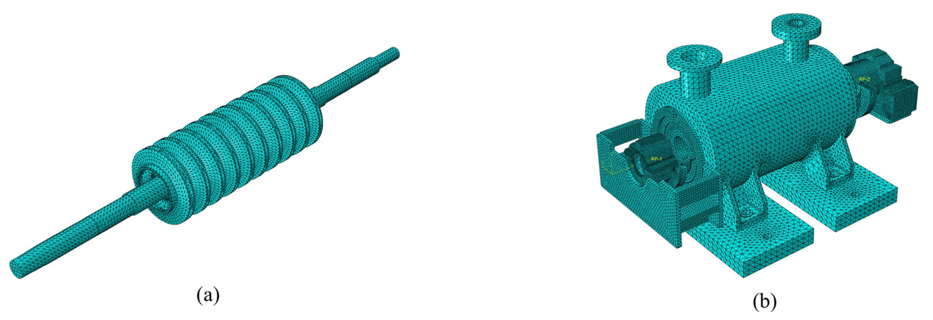
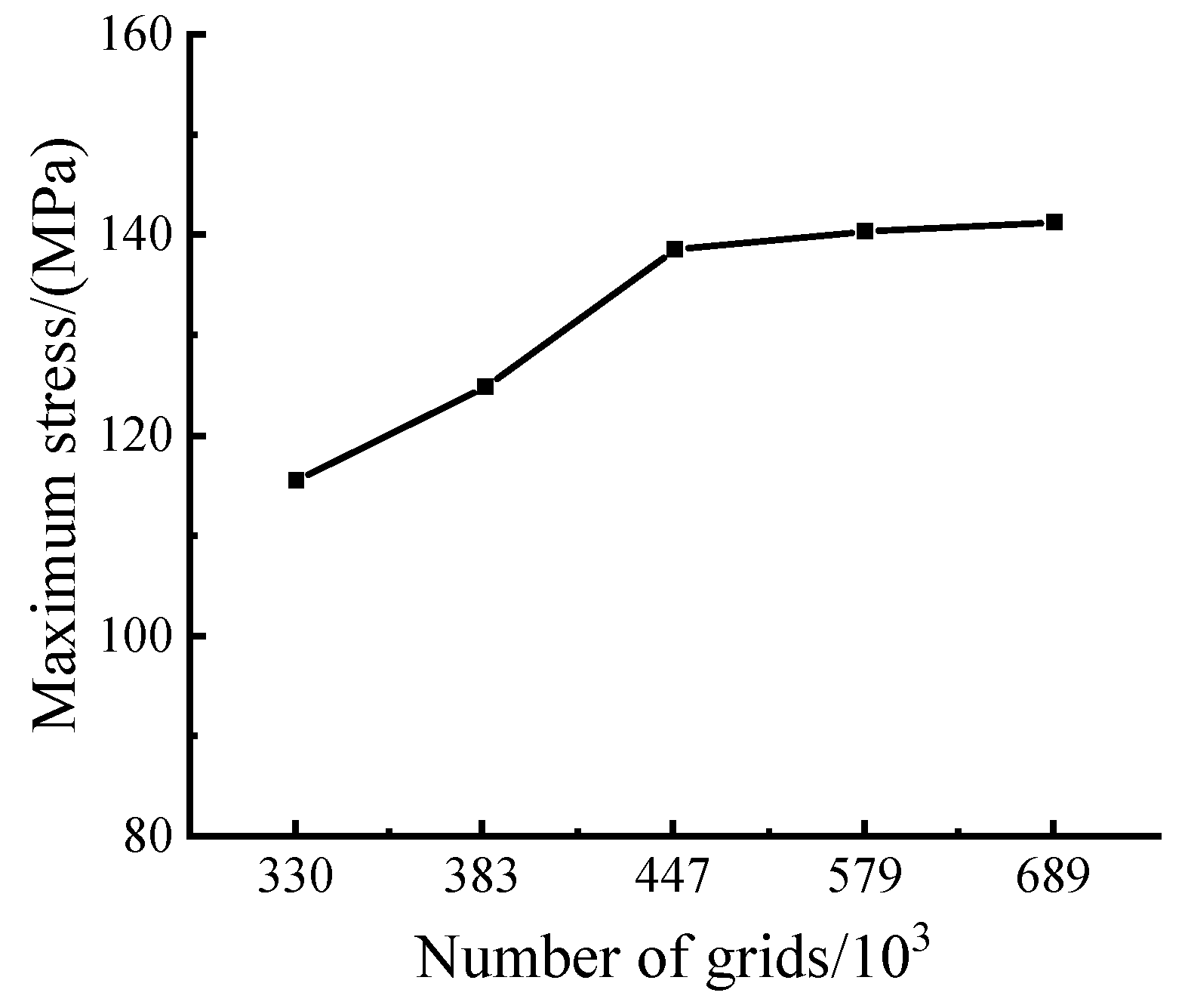
Using ABAQUS 6.13 software, a finite element model is constructed for the auxiliary feedwater electric pump to enable subsequent seismic response analysis [25,26]. Departing from traditional methods using beam and mass units to simulate the rotor, this study adopts three-dimensional solid elements to accurately model the pressure-bearing components and rotating components, aiming for enhanced calculation precision. The machining of holes in non-stressed positions of the pump body structure are simplified, along with processing fillets and chamfers that minimally affect strength. The pump base installation surfaces are constrained using fixed constraints, and constraint contacts are established at the contact areas between the pump cover and pump body, the suction section and pump body, as well as the pump body and pump base. Considering the sliding bearing’s stiffness on the order of 107 N/m, calculations reveal negligible impact on low-order natural frequencies. Therefore, nodal degrees of freedom coupling are implemented between the shaft and the bearing bracket. In Figure 2, a ten-node tetrahedral element meshes the model, with local refinement applied to the impeller, pump base installation surface, and various component contact surfaces. Mesh independence verification, depicted in Figure 3, uses the maximum stress in the pump under seismic excitation in the horizontal 0° direction as a criterion. Results show that when the number of elements exceeds 447,000, the difference in maximum stress is within 1%. Increasing mesh density has minimal impact on results, leading to the adoption of a mesh division scheme with 447,000 elements.

3. Seismic Analysis Methods for Auxiliary Feedwater Electric Pumps

Seismic analysis methods for auxiliary feedwater electric pumps are traditionally classified into three main categories: the static analysis method, the response spectrum method, and the dynamic analysis method. In compliance with pertinent nuclear safety codes in China, seismic analysis calculations for nuclear power equipment may be performed utilizing the static analysis method, provided that the fundamental frequency of the nuclear power equipment surpasses 33 Hz. [27,28,29]. Despite its computational simplicity, this method tends to be overly conservative, leading to substantial margins and failing to accurately capture the structure’s response characteristics. Conversely, the dynamic analysis method offers precision but demands extensive computations, resulting in complex data management challenges [30]. In contrast to these approaches, this study embraces the response spectrum method to scrutinize the response characteristics of the auxiliary feedwater electric pump under seismic inputs from diverse angles. The core computational process is delineated as follows.
The equations of motion for the auxiliary feedwater electric pump under seismic loading are expressed as follows:
M x ¨ + C x ˙ + K x = M x ¨ g ( t )
where M represents the mass matrix, C is the damping matrix, K stands for the stiffness matrix, x denotes the displacement of individual nodes, and xg signifies the relative ground displacement.
In examining the dynamic characteristics of the structure, the equation describing its undamped free vibration is formulated as follows:
M x ¨ + K x = 0
Solutions for the generalized eigenvalue and eigenvector corresponding to Equation (2) can be obtained, revealing the intrinsic frequency and vibration pattern of the auxiliary feedwater electric pump for each order.
The process of vibration mode decomposition entails simplifying the seismic response problem of a pump characterized by multiple degrees of freedom into n independent single-degree-of-freedom system seismic response problems. This simplification is achieved by expressing the dynamic response in modal coordinates, as illustrated in Equation (1). Through decoupling transformations and subsequent solving, the seismic excitation standard value for the pump’s multi-degree-of-freedom system during an earthquake is derived.
F i j = a j γ j X i j G i i , j = 1 , 2 , , n
where Fij represents the seismic excitation standard value corresponding to the j-th mode of the i-th mass point, aj is the seismic influence coefficient of the j-th mode, γj is the participation coefficient of the j-th mode, Xij is the displacement corresponding to the j-th mode of the i-th mass point, and Gi represents the representative value of the gravity load concentrated on the i-th mass point.
The seismic response of the auxiliary feedwater electric pump involves intricate patterns where maximum values of vibration modes do not align simultaneously or in the same direction. Utilizing a simplistic summation of these maximum absolute values would result in an excessively conservative estimation of the total seismic effect, denoted as S. To address this, our study adopts a sophisticated probabilistic analysis method, specifically the square root of the sum of the squares (SRSS). In this approach, we calculate the seismic response, denoted as Sj, for each order of the i-th mass point of the j-th vibration mode in the multi-degree-of-freedom system based on the standard value of horizontal seismic excitation, Fij. Subsequently, we calculate the square root of the sum of the squares Sj at corresponding positions of the vibration modes, facilitating the computation of the total seismic response S at each location.
S = j = 1 n S j 2
where S signifies the total seismic response on the pump, and Sj represents the j-th order seismic response for a certain degree of freedom.

4. Multi-Angle Response Spectrum Analysis Model

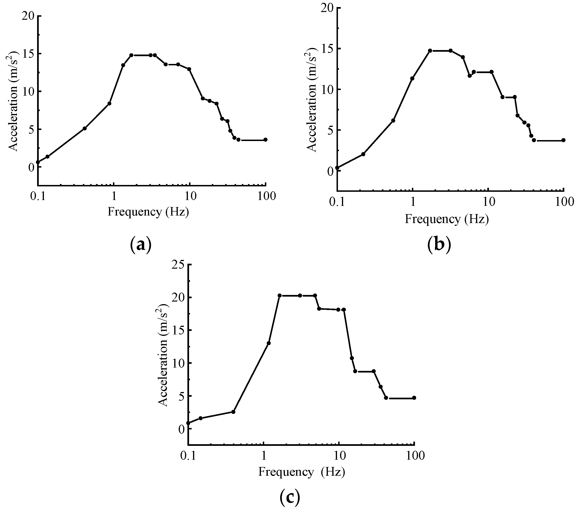
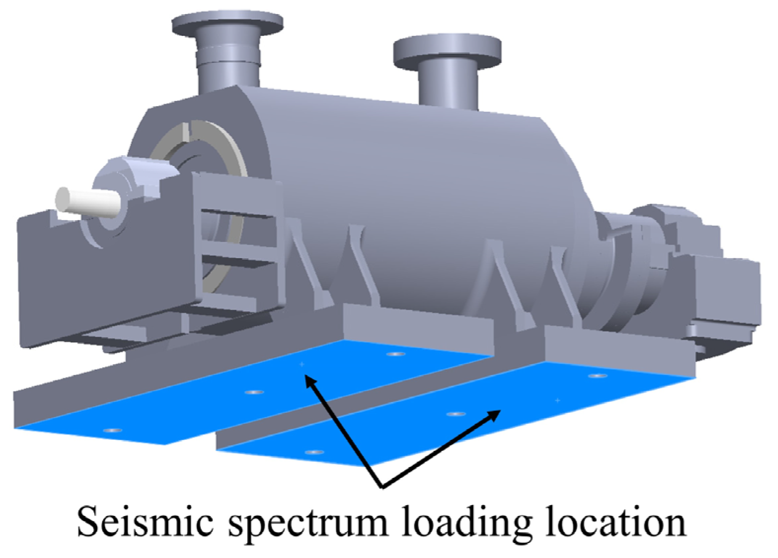
The pump unit is strategically positioned within the reactor plant, a critical aspect for its functionality. In this study, the SSE seismic response spectrum at the pump’s specific location was discretized into three orthogonal directions of acceleration: a vertical z-direction acceleration and two mutually perpendicular horizontal x-direction and y-direction accelerations, as shown in Figure 4. Adhering to the actual installation arrangement of the auxiliary feedwater electric pump, the seismic spectrum was meticulously applied to the pump base mounting surface, as visually represented in Figure 5. This meticulous approach ensures the precise consideration of the pump’s mounting conditions and real-world installation scenario.
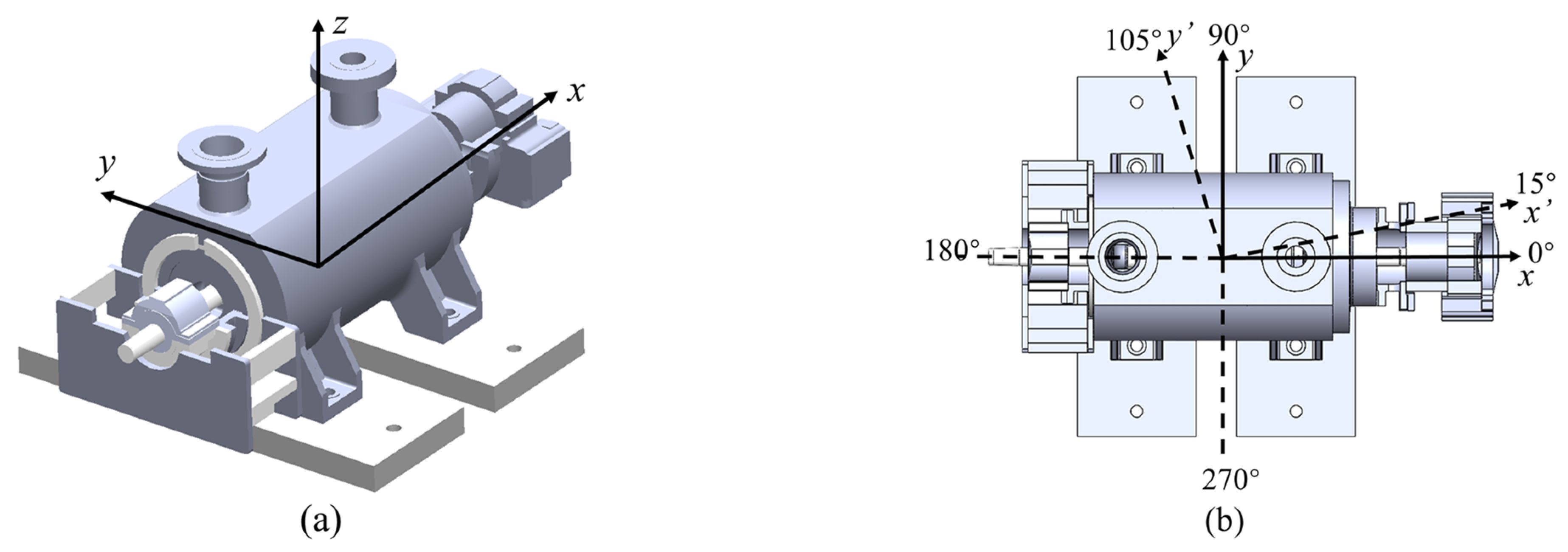
The orientations of the seismic excitation inputs are illustrated in Figure 6. To accommodate various seismic spectrum input directions, both horizontal seismic spectra are concurrently rotated counterclockwise around the vertical z-direction. Throughout this rotation, the angle between the two horizontal seismic spectra is consistently maintained at 90°. Calculations are conducted at 15° intervals spanning from 0° to 180°. Meanwhile, the seismic spectrum input direction along the vertical z-direction remains unchanged in the downward direction. Upon individual computations of seismic responses in these three directions, the cumulative response under simultaneous seismic excitation from all three directions is determined through the SRSS method.
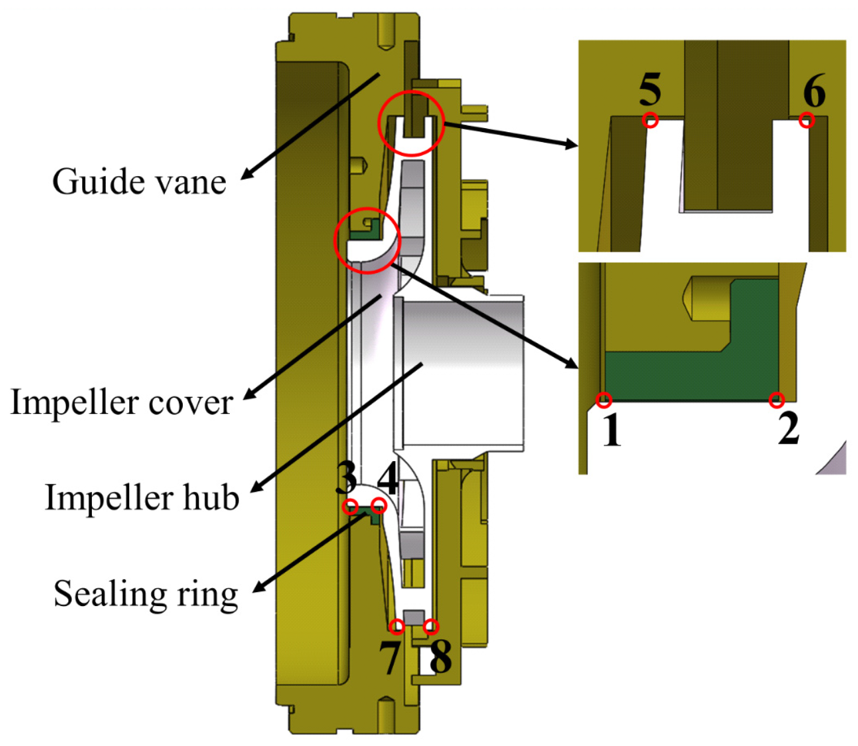
Specialized attention is directed towards the clearances between the rotating and fixed components of auxiliary feedwater electric pumps, a critical focus highlighted in previous studies [31,32,33]. It is imperative to prevent any instances of collision or wear between the impeller cover inlet and sealing ring, as well as between the impeller outlet and guide vane, emphasizing the need for precision engineering in these areas [34]. Seismic excitation can induce deformations, potentially leading to friction or interference, which must not exceed the limits outlined in the RCC-M 2000 standard [35]. Such scenarios pose significant risks, including the potential for nuclear leakage. To meticulously address these concerns, as illustrated in Figure 7, this study strategically establishes monitoring points at specific locations: points 1, 3 and 2, 4 are designated at the front and rear ends of the impeller cover inlet, where the sealing ring is fitted. Additionally, points 5, 7, and 6, 8 are identified on the surfaces of both the impeller cover and the hub at the outlet. These monitoring points serve as crucial markers for investigating displacement responses between the rotor and stator components during seismic excitation.
To visualize the impact of seismic spectrum input angles on the displacement responses of monitoring points and to discern differences among these responses, a deformation factor is defined herein.
D f = D D ¯ D ¯
where Df represents the deformation factor, D ¯ denotes the average displacement value across all input angles for the monitoring point, and D signifies the displacement value of the monitoring point at each specific input angle.

5. Calculations and Analyses

5.1. Modal Analysis Results

To elucidate the fundamental dynamic characteristics of the auxiliary feedwater electric pump, the study conducted an analysis of the first six intrinsic frequencies and their corresponding vibration patterns, as detailed in Table 2 and illustrated in Figure 8. The analysis unveiled predominant vibration modes in the first and second orders, involving bending vibrations along both the horizontal y-direction and the vertical z-direction in the rotor. The maximum deformation is observed at the impellers located in the middle of the rotor, raising concerns about the potential risk of collision and friction between these middle impellers and the guide vanes. The third and fourth orders demonstrated secondary bending vibrations along the horizontal y-direction and vertical z-direction in the rotor. The maximum deformation is identified at the impellers of the first and last stages of the rotor, presenting a potential risk of collision and friction between these impellers and the guide vanes. For the fifth and sixth orders, swing vibrations emerged along the y-direction in the thrust bearing components. Moreover, a subtle lateral swing deformation was observed across the entire pump along the x-direction, with the most significant deformation localized at the thrust bearing. It is noteworthy that the vibration patterns of the auxiliary feedwater electric pump appear in pairs. Specifically, the first four orders of vibration correspond to rotor vibrations, while the stator components remain stationary. Starting from the fifth order, the entire pump exhibits deformations.

5.2. Results of Analysis of Pressure-Bearing Components

The essential pressure-bearing elements of the pump encompass the pump body, pump cover, suction section, and pump base. Any impairment to these components under seismic stress can pose substantial risks to the auxiliary feedwater electric pumps. Therefore, this study meticulously delves into the seismic responses, focusing on stresses and displacements within these critical pressure-bearing elements.
The stress and displacement distribution of the pump body is depicted in Figure 9. As shown in Figure 9a, a high-stress region is evident at the connection between the pump body’s support base and the cylinder. This occurrence is attributed to a significant change in structural stiffness at this location, aligning with the actual conditions under seismic loading. This region is identified as a vulnerable area, warranting focused attention in seismic analysis. Figure 9b indicates that the overall average displacement of the pump body is relatively small. Nevertheless, there is a gradual increase in displacement from the bottom support base to the top at the inlet and outlet, attributed to minimal constraints from the inlet and outlet piping.
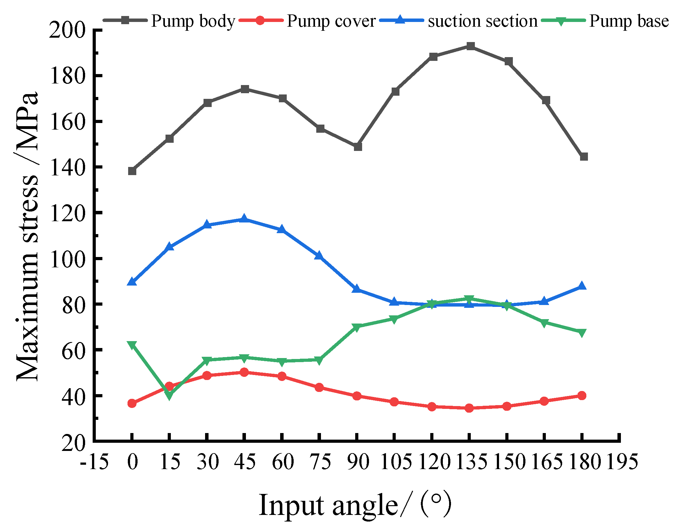
Figure 10 illustrates the curves displaying the maximum stress responses for each pressure-bearing component at various angles, while Table 3 provides details regarding the angles corresponding to the occurrences of these stress maxima.
The pump body displays considerable variability in maximum stress response under different seismic spectrum input angles. Among the pressure-bearing components, it exhibits the highest overall stress response, reaching 174.2 MPa at 45° and 192.9 MPa at 135°, with a breaking point at 90°. Conversely, the maximum stress response of the pump cover remains relatively stable, oscillating around 40 MPa. In contrast, the suction section experiences a stress peak between 0° and 90°, reaching 117.1 MPa at 45°. Between 90° and 180°, especially from 120° to 150°, the stress response remains nearly constant at 79.6 MPa. The pump base shows a significant stress surge between 15° to 30° and 75° to 90°, reaching a pinnacle of 82.4 MPa at 135° while maintaining stability at 56 MPa from 30° to 75°.
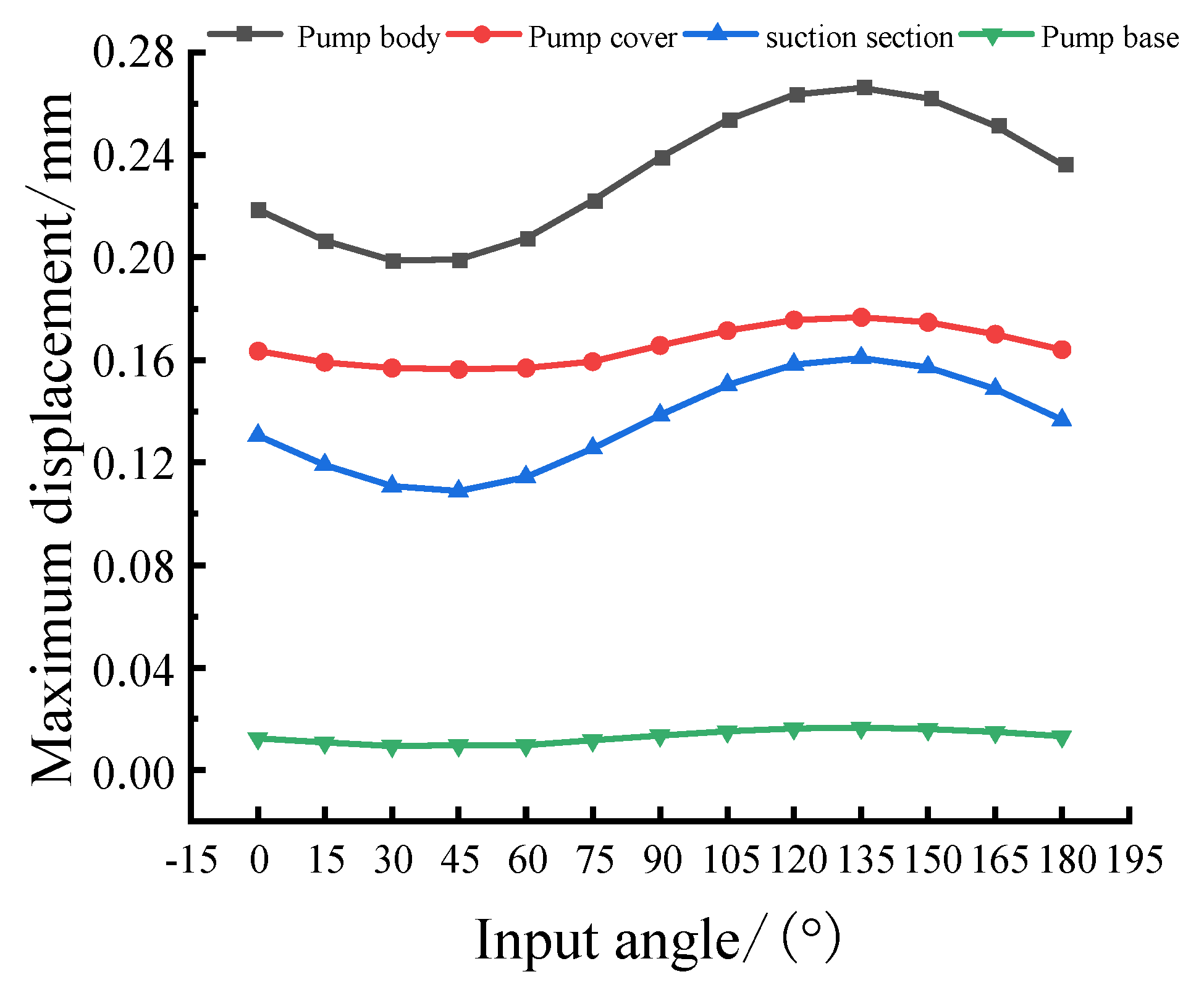
Figure 11 illustrates the maximum displacement response curves of each pressure-bearing component at various angles. It is evident that the maximum displacement response for each component follows a consistent pattern. Peaks occur between 90° and 180°, while troughs are observed between 0° and 90°. Notably, all components reach their peaks at 135°. However, the pump body and suction section exhibit more significant fluctuations in maximum stress response, whereas the pump cover and pump base demonstrate relatively smooth variations.
A thorough analysis of the aforementioned data indicates that despite the consistent seismic spectrum in every input direction, the asymmetrical structure of the pump and the differing structural rigidity of its components lead to shifts in vibration frequencies. Consequently, the maximum stress and displacement responses of each pressure-bearing component vary with different input angles, displaying unique patterns of change. These observed patterns offer crucial insights for the design and installation of pertinent equipment in auxiliary feedwater electric pumps and the nuclear island. They serve as valuable reference points for future endeavors in this field.

5.3. Rotor Analysis Results

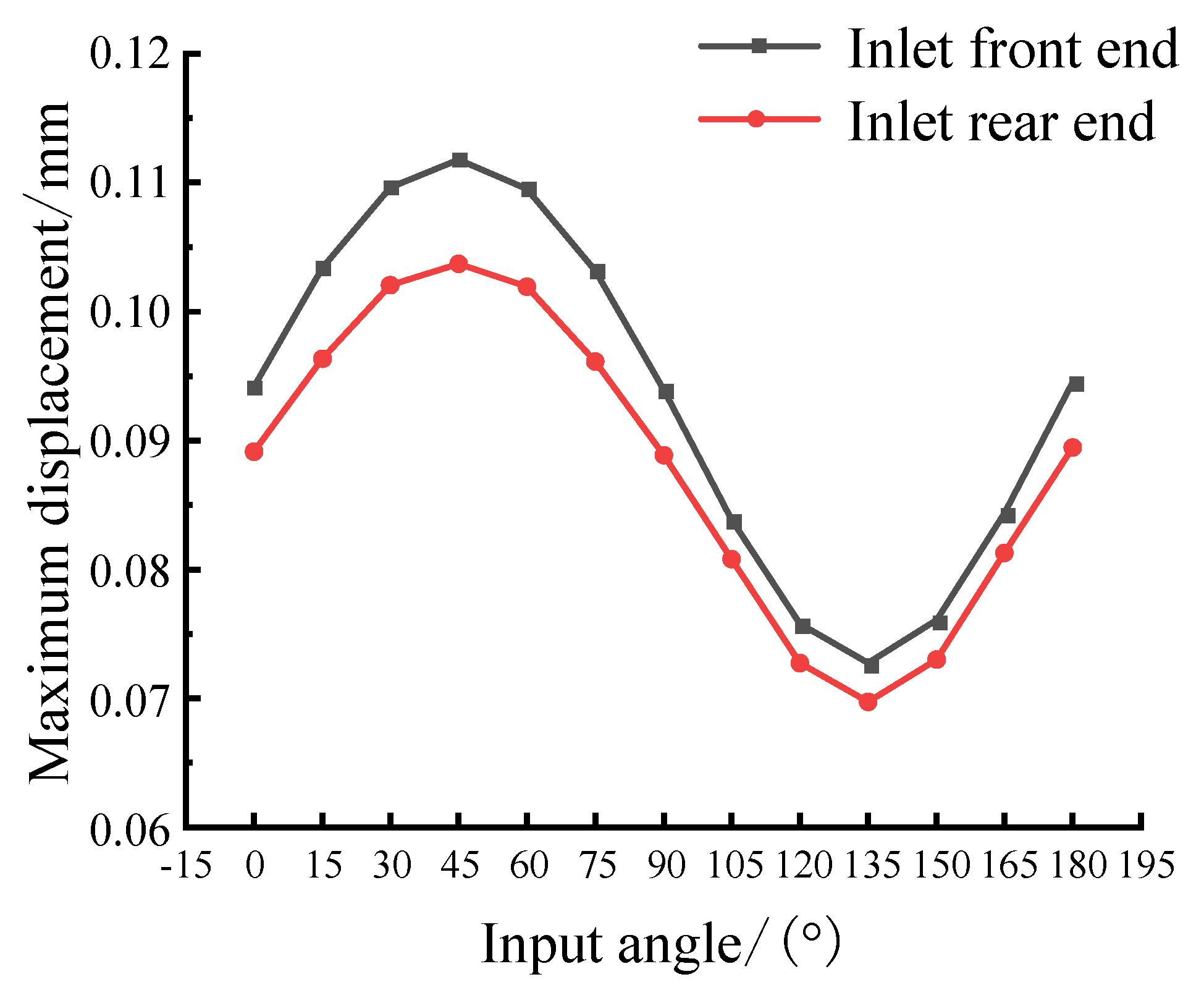
Figure 12 and Figure 13 depict the maximum displacement curves of the impeller cover’s inlet surface and the impeller’s outlet surface, respectively, under various seismic spectrum input angles. Both response curves exhibit a consistent pattern: a peak between 0° and 90°, a trough between 90° and 180°, and a maximum value at 45°. The maximum displacement of the impeller cover’s inlet surface with the sealing ring measures 0.1118 mm, significantly smaller than the actual clearance between the impeller and the sealing ring. Similarly, the maximum deformation of the impeller’s outlet is 0.1319 mm, below the practical clearance between the impeller and the guide vane, ensuring adherence to RCC-M2000 code. Notably, the maximum displacement at the inlet’s front end surpasses that at the rear end across all input angles, indicating a reduction in the inlet’s deformation along the flow direction, especially between 0° and 90°. Furthermore, the impeller cover’s maximum displacements at the impeller outlet exceed those at the hub, indicating the higher fluid excitation force experienced by the impeller cover in comparison to the hub.
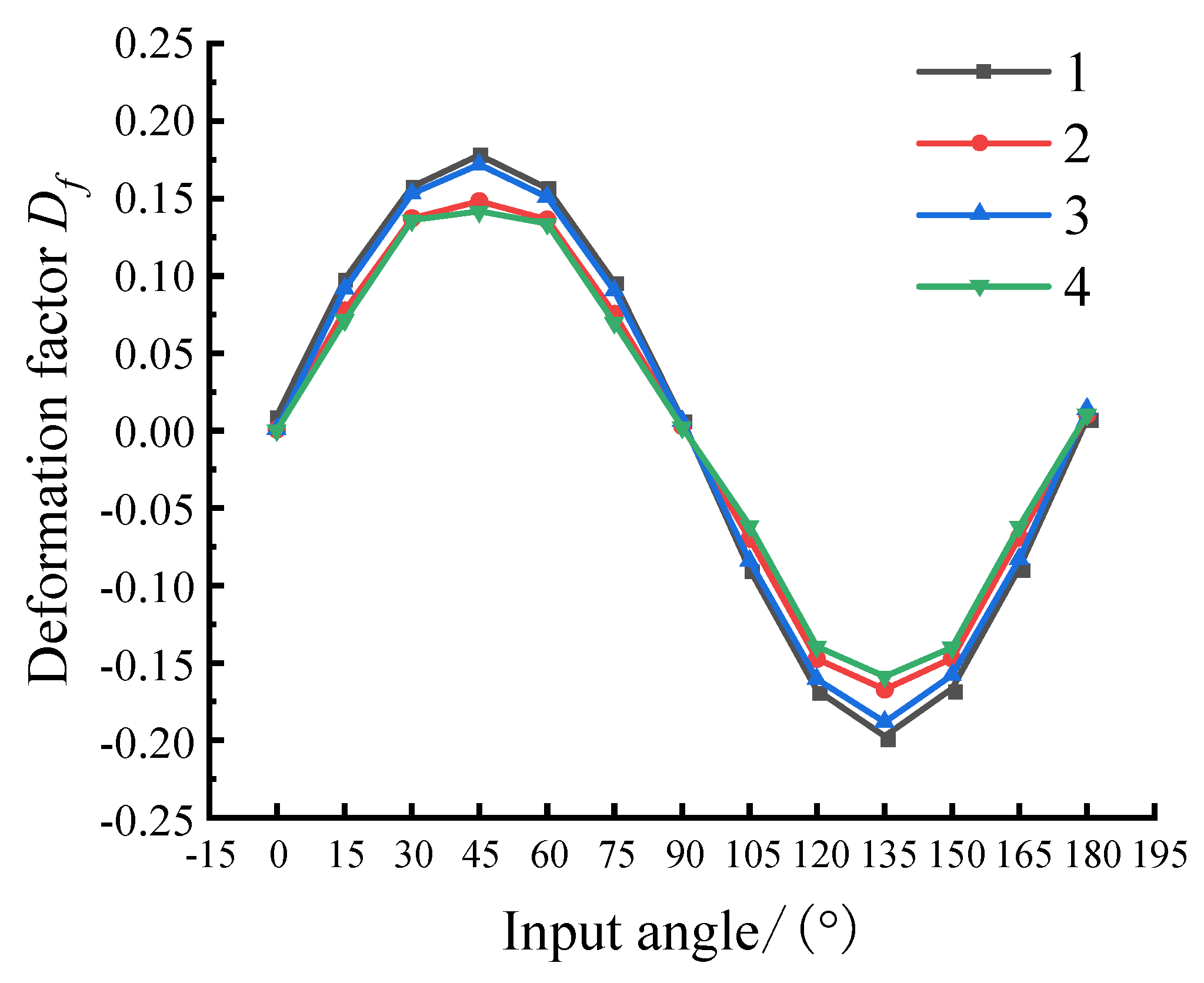
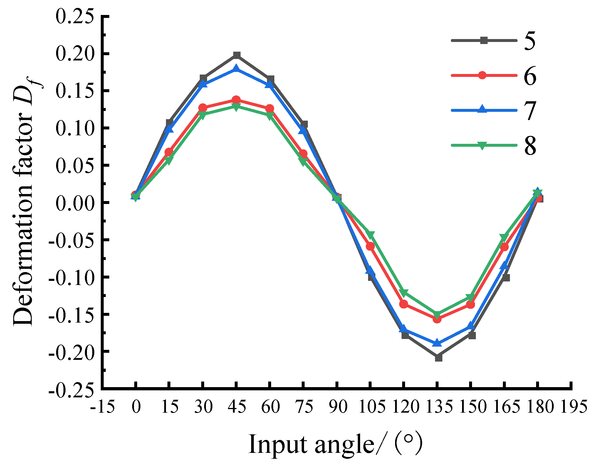
Figure 14 and Figure 15 illustrate the deformation factor curves of the impeller cover’s inlet and impeller outlet surface monitoring points, respectively. Comparative analysis reveals a significant influence of the seismic spectrum input angle on the impeller outlet compared to the impeller cover inlet, underscoring the importance of careful consideration during the design and calibration processes. Generally, the absolute values of the deformation factors at points 1 and 3 are slightly larger than those at points 2 and 4, indicating a minor impact of the input angle on the front and rear ends of the impeller cover inlet. In contrast, the absolute values of the deformation factors at points 5 and 7 are significantly greater than those at points 6 and 8, signifying that the impeller cover is more responsive to displacement changes and fluctuations at different input angles than the impeller hub. Notably, the absolute values of the deformation factors at points 5 and 6 exceed those at points 7 and 8 due to the greater distance of points 5 and 6 from the seismic spectrum loading location, resulting in a more pronounced displacement response. These findings emphasize the need for meticulous attention to these factors in the design and calibration processes.
From the above calculation results, it can be seen that the seismic response characteristics of the rotor in the auxiliary feedwater electric pump exhibit significant variations depending on different directions of seismic spectral input. Notably, distinct extreme values are observed in maximum displacements at 45° and 135°, with 45° representing the peak value. This indicates that for future seismic analyses of auxiliary feedwater electric pumps, prioritizing seismic spectral inputs at this specific angle is crucial to conservatively assess the clearance between their rotors and stators. Moreover, for optimal seismic resilience, the installation angle of the pumps within the nuclear island can be strategically set between 120° to 150°, aligning with the direction of frequent earthquakes. Conversely, angles within 30° to 60° should be avoided whenever possible to mitigate the deformation effects induced by seismic excitation. These insights provide valuable guidance for the design and operational strategies of auxiliary feedwater electric pumps in nuclear power plants, ensuring their robust performance under seismic conditions.

6. Conclusions

This paper utilizes a specific auxiliary feedwater electric pump as a case study and establishes its finite element model. The dynamic response patterns under diverse seismic excitation directions are investigated employing the response spectrum method and the SRSS mode superposition principle. This encompasses the examination of displacement and stress patterns at various pressure-bearing components and critical positions of the rotor. The findings presented herein can serve as a valuable reference for the analysis, design, and installation of similar nuclear power pumps. Based on the analysis and research conducted in this paper, the following conclusions are drawn:
(1)
In seismic response calculations for the pump, the response spectrum method demonstrates high efficiency and is a viable approach for exploring the patterns of dynamic responses.
(2)
The low-frequency components of the multi-stage auxiliary feedwater electric pump mainly stem from the bending vibrations of the rotor. These vibrational patterns have a substantial impact on the clearance between the impeller and stator. Particularly, in scenarios where the excitation forces resulting from seismic events manifest at lower frequencies, the clearance between the impeller and stator emerges as a critical parameter that necessitates comprehensive examination.
(3)
With alterations in the seismic excitation direction, the pump undergoes substantial fluctuations in both maximum stress and maximum displacement responses. This underscores a marked impact of seismic excitation direction on the dynamic response of the pump. Noteworthy is the fact that at the 45-degree direction, the rotor attains its peak displacement, whereas at the 145-degree direction, the maximum stress in pressure-bearing components reaches its zenith. These two directions deserve particular emphasis in the computational analysis.
(4)
The highest stress is observed at the intersection of the support base and the cylinder. In light of considerations for economic feasibility and practicality, it is advisable to undertake structural optimization aimed at reducing stress concentration at this specific location. Additionally, for prospective improvements in pump reliability, avenues such as mitigating inertial forces through measures like employing supportive soft cushions can be explored.

Author Contributions

Conceptualization, Z.T. and J.Y.; methodology, Z.T.; software, C.C.; validation, C.C. and G.L.; formal analysis, G.L.; investigation, Z.T.; resources, Z.T.; data curation, J.Y.; writing—original draft preparation, C.C.; writing—review and editing, Z.T.; visualization, C.C.; supervision, Z.T.; project administration, Z.T. All authors have read and agreed to the published version of the manuscript.

Funding

This research received no external funding.

Institutional Review Board Statement

Not applicable.

Informed Consent Statement

Not applicable.

Data Availability Statement

The data used to support the findings of this study are available from the corresponding author upon request. The data are not publicly available due to privacy.

Conflicts of Interest

The authors declare no conflict of interest.

References

  1. Meng, Y.; Huang, J.Q.; Zhang, C.; Liang, B. Automatic control optimization of closed cooling water pumps in NPP. In Proceedings of the 2019 Chinese Automation Congress (CAC), Hangzhou, China, 22–24 November 2019; IEEE: Piscataway, NJ, USA, 2019; pp. 4251–4255. [Google Scholar] [CrossRef]
  2. Zheng, X.Y.; Yamaguchi, A.; Takata, T. Quantitative common cause failure modeling for auxiliary feedwater system involving the seismic-induced degradation of flood barriers. J. Nucl. Sci. Technol. 2014, 51, 332–342. [Google Scholar] [CrossRef]
  3. Voronov, R.; Alzbutas, R. Optimization of test interval of ignalina nuclear power plant auxiliary feedwater pumps. In Proceedings of the 17th International Conference on Nuclear Engineering, Brussels, Belgium, 12–16 July 2009; Volume 43543, pp. 601–605. [Google Scholar] [CrossRef]
  4. Yang, J.H.; Xiao, Y.T. Analysis and treatment of common failure of the turbine driven auxiliary feedwater pump in one nuclear power station. Sci. Technol. Vis. 2016, 230–231+236. [Google Scholar] [CrossRef]
  5. Wang, W.J.; Du, A.L.; Lv, J.L.; Li, L.; Qiu, C.H. Reliability analysis of turbine-driven auxiliary feedwater pump of a nuclear power plant. In Proceedings of the 2016 11th International Conference on Reliability, Maintainability and Safety (ICRMS), Hangzhou, China, 26–28 October 2016; IEEE: Piscataway, NJ, USA, 2016; pp. 1–6. [Google Scholar] [CrossRef]
  6. Lee, S.H.; Lee, J.H.; Kim, S.K.; Kim, J.B.; Kim, T.W. Improvement of aseismic performance of a PGSFR PHTS pump. Nucl. Eng. Technol. 2020, 52, 1847–1861. [Google Scholar] [CrossRef]
  7. Meng, J.Q.; Yang, S.H.; Wang, Y.F. Three-dimensional seismic analysis and safety evaluation for nuclear pump of nuclear power plant based on the RCC-M code. Adv. Vib. Eng. 2011, 10, 343–352. [Google Scholar]
  8. Li, Z.G.; Li, M.Y.; Zhang, J.R.; Li, B.; Liu, X.B. Seismic analysis of nuclear power plant canned motor pump unit based on integral calculation method. Stavební obzor-Civ. Eng. J. 2016, 25, 1–12. [Google Scholar] [CrossRef]
  9. Huang, X.; Xiong, F.R.; Liu, S.; Qi, H.H.; Huang, Q.; Zhang, K. Research and application of different seismic analysis methods in nuclear power equipment. In Proceedings of the International Conference on Nuclear Engineering, Online, 4–6 August 2021; American Society of Mechanical Engineers: New York, NY, USA, 2021; Volume 85246, p. V001T02A024. [Google Scholar] [CrossRef]
  10. Luo, X.H.; Yang, J.; Song, L. Analysis and research on vibration characteristics of nuclear centrifugal pumps at low flow rates. Energy Rep. 2022, 8, 1273–1282. [Google Scholar] [CrossRef]
  11. Huang, T.; Chen, M.M.; Li, Z.C.; Dong, Z.F.; Zhang, T.J.; Zhou, Z. Impact test of a centrifugal pump used in nuclear power plant under aircraft crash scenario. Nucl. Eng. Technol. 2021, 53, 1858–1868. [Google Scholar] [CrossRef]
  12. Zhou, Z.; Chu, Q.B. Seismic analysis for motor driven auxiliary feed-water pump. Dev. Innov. Mach. Electr. Prod. 2012, 25, 9–11. [Google Scholar] [CrossRef]
  13. Kuang, Z.H.; Liu, Y.; Meng, Y.; Yu, L.Y. Seismic analysis of auxiliary feed water electric pump. Pump Technol. 2013, 14–18. [Google Scholar]
  14. Dong, Z.Q.; Yan, X.W.; Yao, X.L.; Liu, Y.J.; Zhen, H.X.; Zhang, B.W. Analysis of seismic performance of steam driven auxiliary feed-water pump. Pump Technol. 2019, (Suppl. S1), 1–4+13. [Google Scholar]
  15. Li, Y.Z.; Liu, Z.; Zheng, H.E. Research on crack failure of auxiliary feed water pump impeller based on CFD. Nucl. Power Eng. 2020, 41, 130–134. [Google Scholar] [CrossRef]
  16. Li, C.J.; Zhang, H.S. Analysis for the exesssive vibration of the motor-driven auxiliary feedwater pump of HPR1000. China Nuclear Power 2021, 14, 642–648. [Google Scholar]
  17. Xue, Y.L.; Shi, H. Rotor dynamics analysis of high speed pump under earthquake condition. Fluid Mach. 2021, 49, 92–97. [Google Scholar] [CrossRef]
  18. Du, P.C.; Hu, X.D.; Wen, X.; Fei, D.D.; Hou, X.Q.; Min, J.D. Field test and reliability improvement scheme for auxiliary electric feedwater pumps of nuclear power units. Power Syst. Eng. 2023, 39, 61–64. [Google Scholar]
  19. He, J.Q. Theoretical Calculation and Modeling Analysis of Pump Comprehensive Performance Test of Auxiliary Feed Water System. Nucl. Power Eng. 2018, 39, 101–103. [Google Scholar] [CrossRef]
  20. Zhou, W.J.; Chen, H.; Wen, B.C. Seismic response analysis of reactor coolant pump in nuclear power plant. J. Vib. Shock 2006, 32–35+162–163. [Google Scholar] [CrossRef]
  21. Li, H.; Fu, S.B.; Zhao, Q.R.; Wen, B.C. Seismic response spectrum analysis of the single vertical centrifugal pump. Appl. Mech. Mater. 2011, 121–126, 1450–1454. [Google Scholar] [CrossRef]
  22. Zhou, W.X.; Zhang, J.G.; Wang, D.Z. Analysis and assessment on seismic response of reactor coolant pump in nuclear power plant. At. Energy Sci. Technol. 2011, 45, 54–59. [Google Scholar]
  23. Deng, X.; Yuan, S.Q.; Yuan, J.P.; Si, Q.R.; Li, Y.L.; Zhu, Y.W. Antiseismic response research of horizontal residual heat removal pump in different seismic spectrum input directions. J. Vibroeng. 2014, 16, 1306–1317. [Google Scholar] [CrossRef]
  24. Tong, L.L.; Duan, R.; Cao, X.W. Seismic analysis of RCS with finite element model for advanced PWR. Prog. Nucl. Energy 2015, 79, 142–149. [Google Scholar] [CrossRef]
  25. Kostarev, V.V.; Petrenko, A.V.; Vasilyev, P.S. An advanced seismic analysis of an NPP powerful turbogenerator on an isolation pedestal. Nucl. Eng. Des. 2007, 237, 1315–1324. [Google Scholar] [CrossRef]
  26. Zhu, X.Y.; Weng, G.Y. Study on earthquake failure mechanism and failure mode of cable-stayed pipeline bridge considering fluid–structure coupling. Appl. Sci. 2023, 13, 9583. [Google Scholar] [CrossRef]
  27. GB50267-97; Code for Seismic Design of Nuclear Power Plants. China Earthquake Administration: Beijing, China, 1998.
  28. HAF 0215(1); Chinese Nuclear Safety Regulations, Seismic Design and Qualification for Nuclear Power Plant. International Atomic Energy Agency: Vienna, Austria, 2003.
  29. Liu, Y.; Chen, D.J.; Wang, D.Z.; Zhang, J.G.; Hu, Y.Y.; Ran, H.J. Seismic calculation and analysis of a long-axis multi-stage molten salt pump used in solar thermal power station. J. Vib. Shock 2021, 40, 148–155+170. [Google Scholar] [CrossRef]
  30. Cheng, D.; Yao, Z.Q.; Xue, Y.B.; Hong, S. Numerical study on seismic response of the reactor coolant pump in Advanced Passive Pressurized Water Reactor. Nucl. Eng. Des. 2014, 278, 39–49. [Google Scholar] [CrossRef]
  31. Cui, Y.; Zhang, C.; Zhang, L.W.; Song, K.J. Evaluation of service reliability of AP1000 nuclear reactor coolant pump rotor-can. Ann. Nucl. Energy 2022, 172, 109073. [Google Scholar] [CrossRef]
  32. Zhang, H.H.; You, H.L.; Lu, H.S.; Li, K.; Zhang, Z.; Jiang, L.X. CFD-rotordynamics sequential coupling simulation approach for the flow-induced vibration of rotor system in centrifugal pump. Appl. Sci. 2020, 10, 1186. [Google Scholar] [CrossRef]
  33. Wang, R.; Guo, X.L.; Wang, Y.F. Nonlinear analysis of rotor system supported by oil lubricated bearings subjected to base movements. Proc. Inst. Mech. Eng. Part C J. Mech. Eng. Sci. 2016, 230, 543–558. [Google Scholar] [CrossRef]
  34. Presas, A.; Valentin, D.; Valero, C.; Egusquiza, M.; Egusquiza, E. Experimental measurements of the natural frequencies and mode shapes of rotating disk-blades-disk assemblies from the stationary frame. Appl. Sci. 2019, 9, 3864. [Google Scholar] [CrossRef]
  35. RCC-M (Edition 2000+ Addendum 2002); Design and Construction Rules for Mechanical Components of PWR Nuclear Islands. AFCEN: Paris, France, 2002.
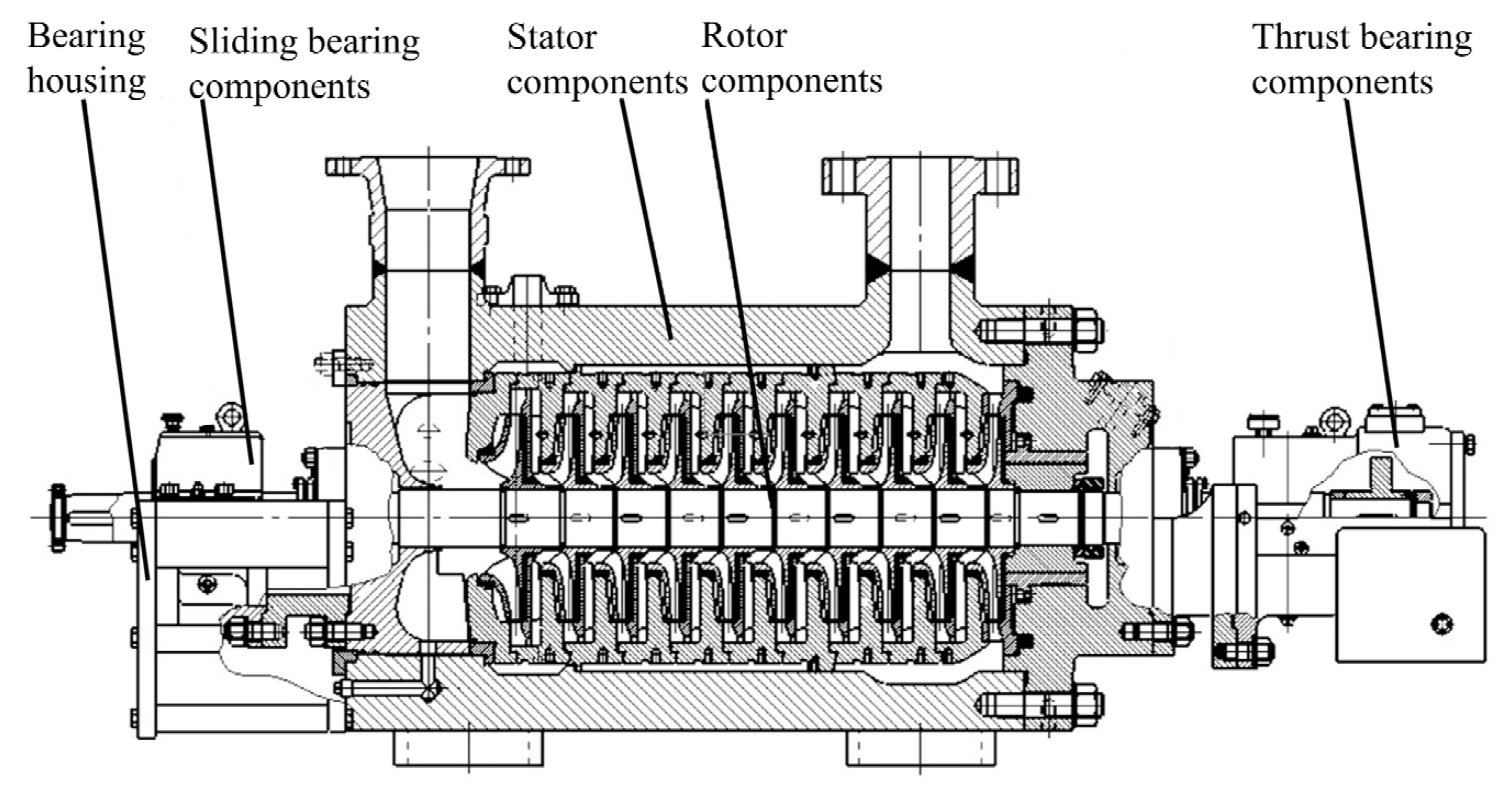
Figure 1. General structure of auxiliary feedwater electric pumps.
Applsci 14 00028 g001
Figure 2. Finite element model of auxiliary feedwater electric pumps. (a) Rotor. (b) Stator.
Applsci 14 00028 g002
Figure 3. Mesh independence verification.
Applsci 14 00028 g003
Figure 4. Floor acceleration response spectrum. (a) Horizontal x-direction, (b) horizontal y-direction, (c) vertical z-direction.
Applsci 14 00028 g004
Figure 5. Seismic spectrum loading location.
Applsci 14 00028 g005
Figure 6. Schematic diagram of seismic spectrum input angle. (a) Coordinate direction diagram. (b) Input angle schematic.
Applsci 14 00028 g006
Figure 7. Impeller monitoring points.
Applsci 14 00028 g007
Figure 8. Modal vibration patterns of auxiliary feedwater electric pumps.
Applsci 14 00028 g008aApplsci 14 00028 g008b
Figure 9. Stress and displacement cloud diagram of pump body. (a) Stress. (b) Displacement.
Applsci 14 00028 g009
Figure 10. Maximum stress response of the pressure-bearing components at different angles.
Applsci 14 00028 g010
Figure 11. Maximum displacement response of the pressure-bearing components at different angles.
Applsci 14 00028 g011
Figure 12. Maximum displacement of impeller cover inlet surface.
Applsci 14 00028 g012
Figure 13. Maximum displacement of impeller outlet surface.
Applsci 14 00028 g013
Figure 14. Deformation factor of the monitoring point of the impeller cover inlet.
Applsci 14 00028 g014
Figure 15. Deformation factor of the monitoring point of the impeller outlet surface.
Applsci 14 00028 g015
Table 1. Material parameters of auxiliary feedwater electric pumps.
PartsMaterialsDensity/(kg/m3)Poisson’s RatioModulus of Elasticity/GPaYield Strength/MPa
Pump body, pump cover, suction section022Cr19Ni1079000.3200225
Pump baseQ235B78500.3203235
Shaft05Cr16Ni5Mo79300.3200685
Bearing housingZG06Cr13Ni4Mo77500.3200550
Table 2. First 6 orders of intrinsic frequency.
Order123456
f/Hz41.0641.09171.54171.6242.9278.18
Table 3. Angle of maximum and minimum values of maximum stresses.
Pump BodyPump CoverSuction SectionPump Base
Angle of maximum value135°45°45°15°
Angle of minimum value135°150°135°
Disclaimer/Publisher’s Note: The statements, opinions and data contained in all publications are solely those of the individual author(s) and contributor(s) and not of MDPI and/or the editor(s). MDPI and/or the editor(s) disclaim responsibility for any injury to people or property resulting from any ideas, methods, instructions or products referred to in the content.