Article

Design and Characterization of an Upscaled Dielectric Barrier Discharge-Based Ten-Layer Plasma Source for High-Flow-Rate Gas Treatment

1
Laboratory for Future Interdisciplinary Research of Science and Technology, Tokyo Institute of Technology, Yokohama 226-8502, Japan
2
Graduate School of Interdisciplinary New Science, Toyo University, Saitama 350-8585, Japan
*
Authors to whom correspondence should be addressed.
Appl. Sci. 2024, 14(1), 27; https://doi.org/10.3390/app14010027
Submission received: 2 December 2023 / Revised: 17 December 2023 / Accepted: 18 December 2023 / Published: 19 December 2023
(This article belongs to the Section Electrical, Electronics and Communications Engineering)

Abstract

:
Dielectric barrier discharge (DBD)-based technology is considered a promising alternative for controlling indoor air pollutants. However, its limited processing capacity and lack of design techniques have restricted its use in practical applications. This paper introduces a methodology for designing upscaled DBD reactors with a processing capacity of up to 1000 L/min for treating high-flow-rate gases to mitigate indoor air pollution. A ten-layer high-flow-rate DBD reactor was constructed, with fundamental characterizations, including electrical and spectroscopic measurements, conducted to verify the feasibility of the proposed methodology. In particular, the flow paths of the ten-layer DBD reactor were optimized by incorporating an air diffuser and perforated metal plates, all without significant modifications. Computational fluid dynamics simulations showed a remarkably improved velocity uniformity (0.35 m/s to 0.04 m/s, as evidenced by the velocity standard deviation) in the 10 flow channels. These simulation results were consistent with the experimental results, wherein the velocity standard deviation reduced from 1.38 m/s to 0.13 m/s. Moreover, multi-gas plasma ignition for up to six gas species and high-flow-rate plasma generation of up to 1000 L/min were achieved. These results provide the foundation for developing DBD technologies for practical applications in high-flow-rate gas treatment, particularly for controlling indoor air pollution.

1. Introduction

Air pollution has emerged as one of the dominant environmental and human health hazards, causing an estimated 8.8 million deaths worldwide each year [1]. Air pollution refers to two aspects of contamination of the living environment: indoor and outdoor air pollution by chemical activities or physical and biological agents that alter the natural characteristics of the atmosphere. In particular, indoor air pollution poses a greater risk to human health than outdoor pollution because indoor pollutant levels can be twice that of outdoor pollution or even higher, which is attributable to a lack of ventilation. In addition, people generally spend the majority of their time indoors [2]. In addition to the typical sources of pollutants (e.g., stationary sources, including the combustion of fossil fuels and traditional biomass, manufacturing sectors, and construction; mobile sources such as diesel exhaust; and natural sources due to volcanic activities and dust) that contribute to outdoor air pollution, indoor air pollution has its characteristic contributors (volatile organic compounds (VOCs) coming from building materials, odor components, indoor airborne transmission through bacterial and viral aerosols such as COVID-19), which have detrimental effects on human health (e.g., lung cancer, sick building syndrome, etc.) [1]. Numerous measures have been implemented to alleviate the adverse effects of indoor air pollution. Mechanical ventilation systems are typically used as a relatively cost-effective approach to bringing fresh outdoor air into buildings by diluting indoor air pollutants. Moreover, active elimination devices for indoor air pollutants using either physical, chemical, or biological technologies (e.g., mechanical and electronic filtration, absorption by activated carbons or zeolites, O3-mediated reactions by ozonizers, etc.) have also proven to be effective when integrated into ventilation systems. However, the diversity, variability, and low concentrations of indoor air pollutants limit the performance of these technologies, necessitating a versatile option that can address these issues [2].
Non-thermal plasma (NTP) technology, also referred to as cold plasma or non-equilibrium plasma, is considered another promising option for controlling indoor air pollutants and is expected to overcome the limitations resulting from the natural characteristics of such pollutants. Additionally, because NTP technology (e.g., low-temperature atmospheric plasma) can free the plasma generation system of vacuum chambers as well as generate plasma containing abundant reactive species (e.g., in humid air-driven plasma, reactive oxygen species: O, O2, O3 and OH, and reactive nitrogen species including NO, NO2, etc. [3,4]) at low temperatures (even room temperature), various forms of NTPs have been developed for a multitude of scientific and industrial applications, including disinfection and sterilization [4,5,6], medicine [7,8,9], chemical analysis [10,11,12], thin film deposition [13,14], waste purification [15,16,17], agriculture [18,19,20], and surface modification [10,21,22]. Among these, dielectric barrier discharge (DBD) plasma is the most promising and suitable plasma source for the abatement of indoor air pollutants owing to its superior characteristics, including its capacity for uniform large-volume plasma generation, simple configuration, lower energy consumption, the effectiveness of multiple pollutant decomposition, bactericidal and disinfectant effects, and operation under ambient conditions, as demonstrated in numerous studies [15,23,24,25,26,27,28]. Thus, DBD-based technology is perceived as an excellent potential reinforcement for conventional building ventilation systems installed to handle concentrated indoor air pollutants in buildings such as densely populated workplaces, hospitals, large shopping malls, and so on.
However, a low processing capacity (less than a few L/min of gas flow at the lab scale) and lack of knowledge of various characteristics of the DBD plasma at high gas flow rates are the major drawbacks that hinder the practical application of DBD plasma to the abatement and control of indoor air pollutants [28,29,30,31]. Moreover, all the design methodologies and optimizations, such as the treatment of building ventilation air and industrial exhaust, are confined to the laboratory scale and are thus impractical for real-world applications. Therefore, there is a strong demand for large-flow DBD systems, which can treat large volumes of polluted gases. To address this issue, several studies have proposed a stacked DBD configuration (also referred to as multilayer configuration) as an effective scenario for upscaling the planar DBD-based systems to control air pollution [32,33,34]. However, none of them have presented a detailed design methodology, and many were combined into a more complex system to realize high performance, which makes them difficult to construct at a low cost. In contrast, another idea that upscales the cylindrical DBD reactors is to use a catalytic monolith to support a large-volume discharge zone, while the overall system and discharge characteristics are confined by the geometric size of the monolith [35,36,37,38]. In this regard, as has been shown previously, two types of high-flow-rate DBD reactors, specifically single- and two-layer DBD reactors, have been developed [29]. These reactors can treat exhaust gases at flow rates that are two orders of magnitude greater (up to 110 L/min) compared to those of small-flow DBD reactors, which are typically limited to 1 L/min or lower. Additionally, they achieved a high decomposition rate of 59.5% on toluene with an initial concentration of 100 ppm when a power of 41 W was applied in the two-layer case. The decomposition characteristics were also obtained at different applied voltages, flow rates, flow velocities, and discharge lengths. The results also indicated the feasibility and superiority of the multilayer configuration scheme for upscaling DBD reactors with high throughput. Nevertheless, further processing capabilities (e.g., 1000 L/min or higher) are still required to realize practical applications with high efficiency, constructed in a straightforward system.
To address this need, an upscaled, high-flow-rate, ten-layer DBD reactor with a processing capacity of up to 1000 L/min was designed and fabricated in this study, which serves as an upgraded version of the previously reported single- and two-layer DBD reactors [29]. Furthermore, its complete design techniques and fundamental characteristics were demonstrated. The flow path design of the ten-layer DBD reactor was validated via computational fluid dynamics (CFD) simulations and empirical measurements. In addition, multi-gas ignition involving various gases such as air, Ar, He, N2, O2, and CO2, as well as electrical and spectroscopic characterizations at high flow rates (50−1000 L/min), were conducted. Therefore, the proposed design methodology is expected to lay the foundation for developing practical DBD reactor systems aimed at indoor air quality control.

2. Materials and Methods

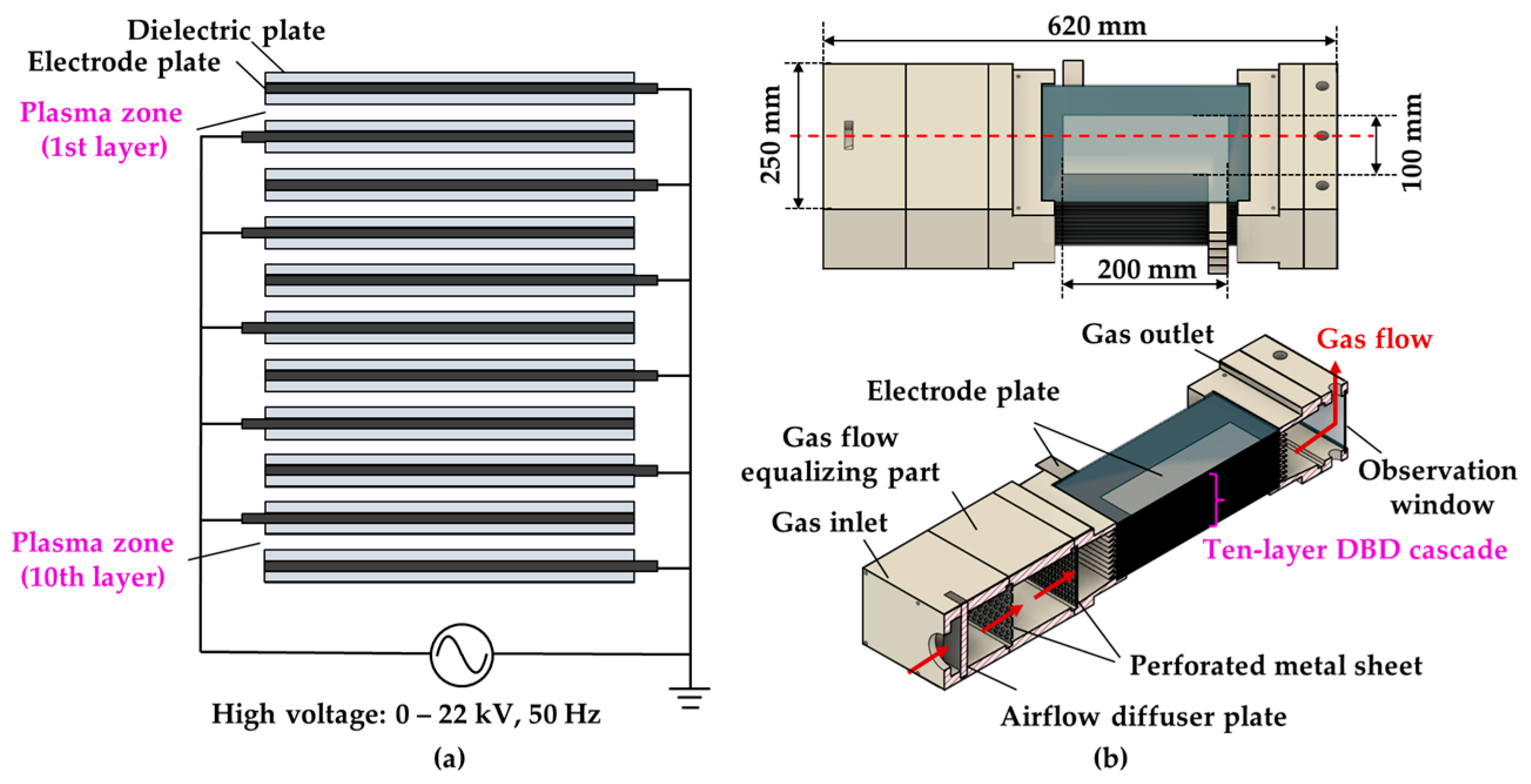
2.1. Rationale for the Upscaled High-Flow-Rate DBD Reactor: Ten-Layer DBD Reactor

The design and fabrication of an upgraded, high-flow-rate, ten-layer DBD reactor were completed. The design schemes of the ten-layer DBD reactor are depicted in Figure 1, which is composed of 10 identical single-layer DBD units; each unit can generate one layer of plasma, which is accomplished by two Al plates (200 mm × 100 mm × 1 mm) serving as electrodes. Each Al plate was attached with two glass plates (250 mm × 200 mm × 2 mm) on both sides, acting as insulating dielectrics (relative permittivity: κ = 7–7.5). In addition, the two glass-covered Al plates were partitioned by two polytetrafluoroethylene sheets (250 mm × 50 mm × 2 mm) at the edges to form a discharge space of 40 cm3 per DBD unit, with a discharge gap of 2 mm. A ten-layer DBD cascade with a 400 cm3 discharge space was constructed by stacking 10 DBD units with alternating high-voltage and ground electrodes, as shown in Figure 1a. With the ten-layer DBD cascade as the gas treatment part, a high-flow-rate, ten-layer DBD reactor was established with a gas inlet, a gas flow equalizing part (including an airflow diffuser plate and two perforated metal plates with 3 and 5 mm holes), and a gas outlet, as rendered in the overall view (upper), as well as in the cross-sectional view (lower) in Figure 1b. Thus, the design scheme enabled a small-footprint and easily scalable high-flow-rate DBD reactor with a height of only 75 mm and 10 DBD units (12 mm in height) that could also be modulated in the vertical direction.

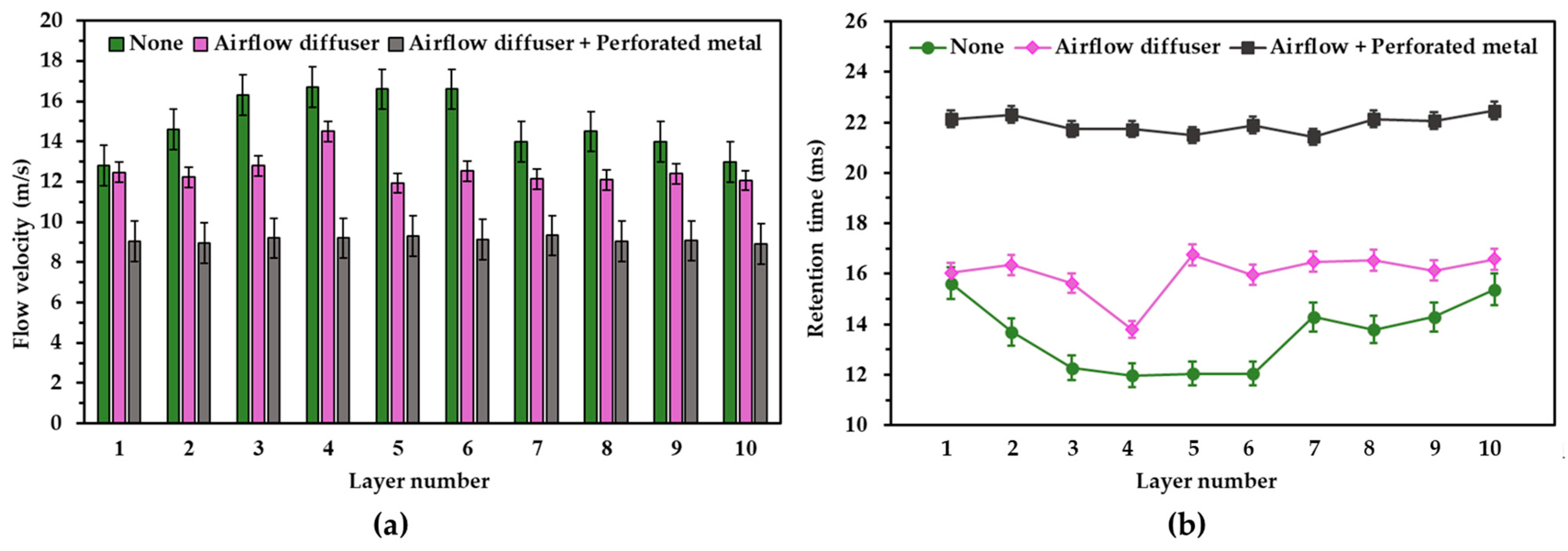
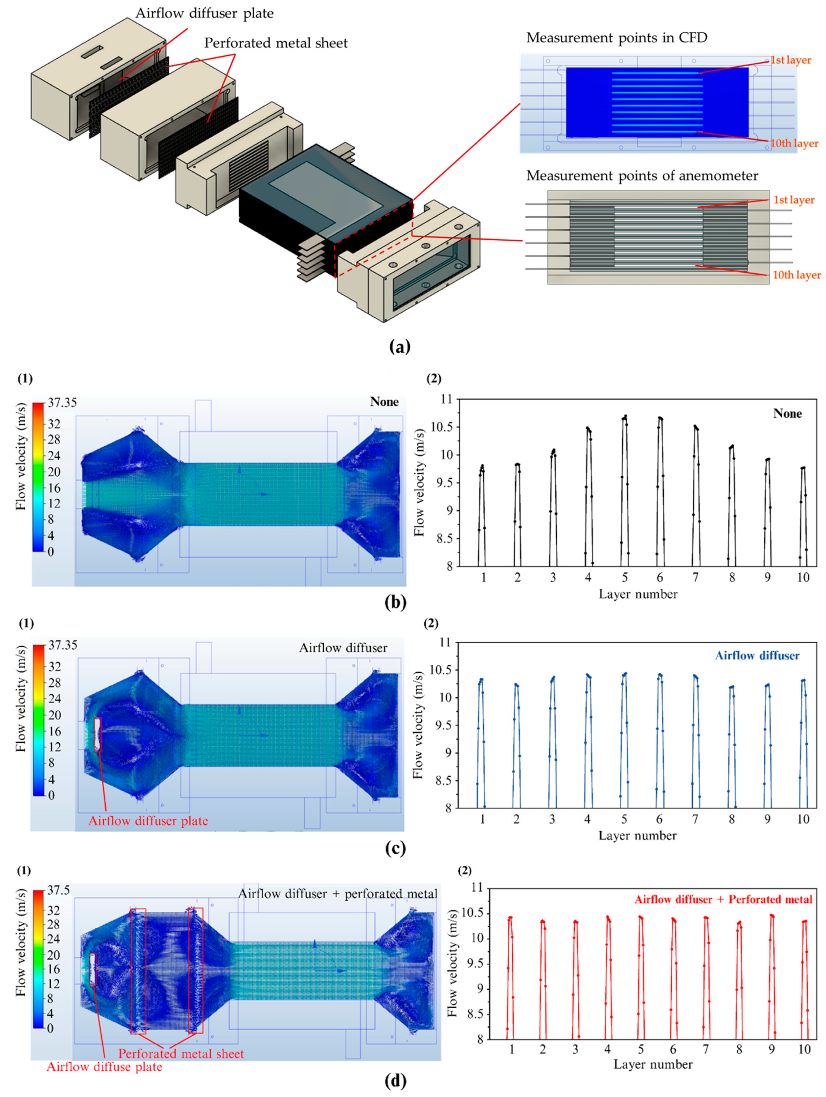
2.2. CFD Simulation-Assisted Flow Path Design

Ensuring a uniform airflow in each flow channel of the ten-layer DBD reactor is indispensable for achieving stable and homogeneous plasma generation in each layer, thereby maximizing the optimum performance. Therefore, fluid dynamics simulations were conducted during the process of designing a ten-layer, high-flow-rate DBD reactor to gain insight into the fluid dynamics of the flow path [39,40,41]. The Autodesk CFD simulation software (Autodesk CFD 2023 23.0, Autodesk Inc., San Rafael, CA, USA) was used. To verify the velocity field of the 10 channels in the ten-layer DBD reactor, the governing equations describing the conservation of mass and momentum are as follows; the continuity and Navier–Stokes equations for an incompressible flow were discretized and solved using the finite element method (FEM). Because the fluid flow introduced into the ten-layer DBD reactor was treated as a turbulent incompressible flow in this study, the continuity equation can be written as follows [40,41,42]:
ρ t + ρ · u = 0
where u represents the flow velocity vector, and ρ and t are the fluid density and time. The Navier–Stokes equation is given by Equation (2) [40,42,43].
ρ u t + ρ ( · u ) u = ρ g P + μ 2   u
therein, the components of g, P, and μ denote the gravitational acceleration vector, pressure, and dynamic viscosity, respectively.
Three models, without an airflow diffuser plate or a perforated metal plate (Model 1: none), with an airflow diffuser plate alone (Model 2: airflow diffuser), and with both (Model 3: airflow diffuser + perforated metal), were established to investigate the flow velocity per channel of the ten-layer DBD reactor during the design phase. For all models, the air was set as the working fluid, whose boundary conditions, including the flow rate at the inlet surface and the pressure at the outlet surface of the flow volume, were set to 1000 L/min and 0 psi (pounds per square inch), respectively, with no heat transfer. Moreover, the mesh size of all models was implemented with the Automatic Meshing function, where the following parameters—i.e., Resolution factor = 1.000, Edge growth rate = 1.100, Minimum points on edge = 2, Points on longest edge = 10, Surface limiting aspect ratio = 20, and Volume growth rate = 1.35—were prescribed. Thus, the configurations of the mesh distribution for the three models were defined. Table 1 provides the analytical information with which the simulations were performed. Notably, the temperature transfer and plasma ignition were not considered in the CFD simulations in this study.
In addition to CFD simulation verification, practical velocity measurements were performed for each channel using a hot-wire anemometer (TSI 9565-A, TSI Incorporated, Shoreview, MN, USA) at a temperature of 24 °C and atmospheric pressure, and the results were in agreement with those obtained by the simulation. Furthermore, optical emission spectroscopy (OES) using a spectrometer (Maya2000Pro, Ocean Photonics, Tokyo, Japan) and an optical fiber (P600-1-SR, Ocean Insight, Orlando, FL, USA) with wavelengths between 200 and 1100 nm was performed to verify the uniformity of plasma generation in each channel of the ten-layer DBD reactor using the optical emission intensity. To ensure fidelity, all measurements were repeated at least three times at three measurement points and averaged.

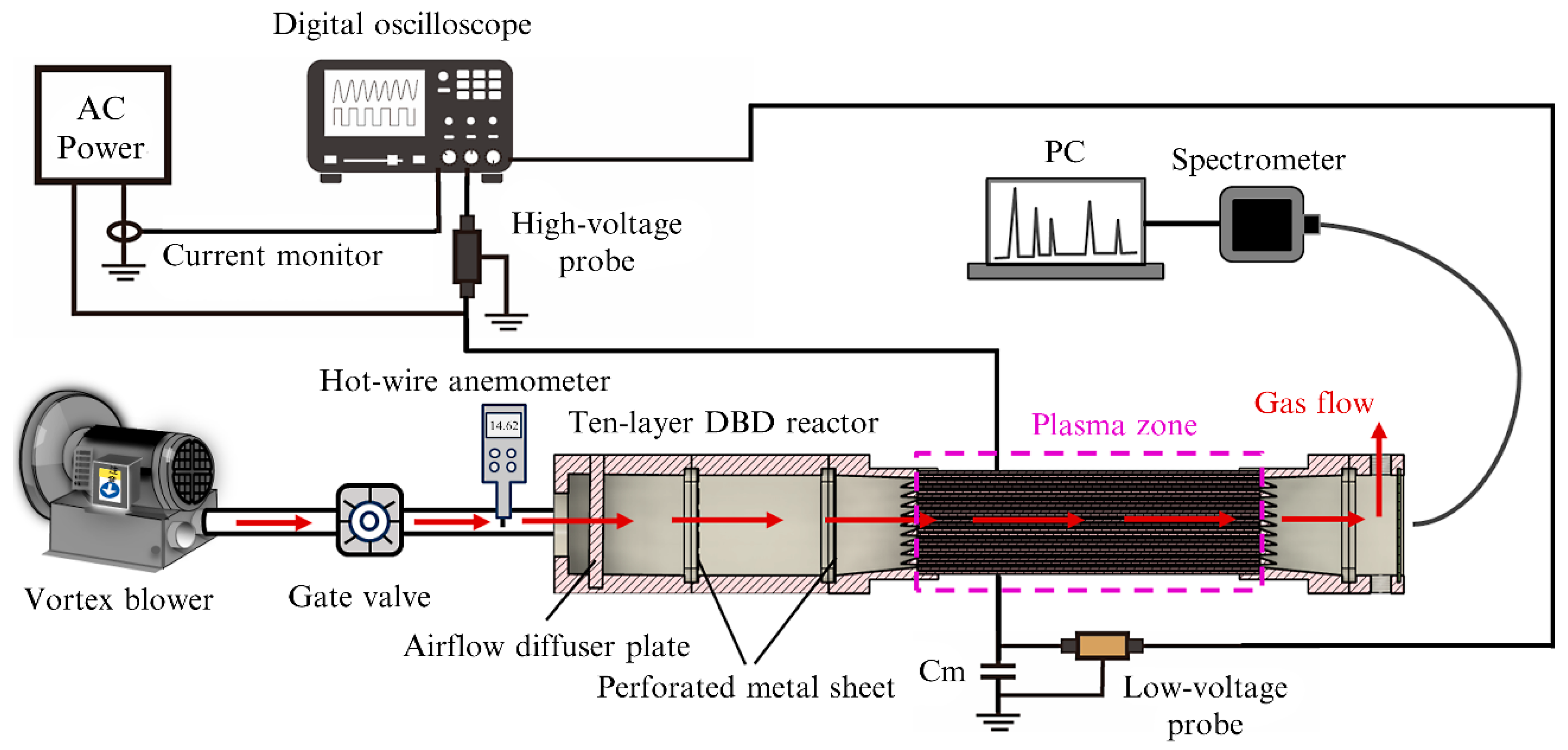
2.3. Experimental Setup

Figure 2 shows the experimental setup. It has four basic parts: a gas flow control section, an AC power source, a ten-layer DBD reactor, and electrical and spectroscopic measurement instruments. The gas flow of air introduced into the ten-layer DBD reactor was induced by a vortex blower (VB-003S-E2, Hitachi Industrial Equipment Systems Co., Tokyo, Japan), and the flow rates of the airflow to be treated were adjusted using a gate valve and hot-wire anemometer (TSI 9565-A). To power the ten-layer DBD reactor, a 50 Hz AC power supply (voltage range: 0–22 kV, zero-to-peak value) was chosen. The waveforms of the applied voltage and current were analyzed using a digital oscilloscope (DPO4104, Tektronix, Tokyo, Japan) with a current monitor (4100, Pearson Electronics Inc., Palo Alto, CA, USA) and a 1000:1 high-voltage probe (HPV-39pro, Pintek, Beijing, China). Moreover, the power consumption of the entire setup and the ten-layer DBD reactor (i.e., discharge power: the power deposited to the plasma discharge) was monitored using a watt meter (TAP-TST8N, Sanwa Supply Inc., Okayama, Japan) and calculated using Lissajous figures observed using a capacitor (Cm = 1 μF). The average dissipated power in the plasma discharge is the product of the Lissajous figure area and power supply frequency (i.e., 50 Hz) [44,45,46]. The capacitance of the ten-layer DBD reactor during plasma discharge was also calculated from the Lissajous figures. The spectroscopic properties were investigated using a spectrometer (Maya2000Pro), whereas the gas temperature of the plasma was determined using a fiber-optic temperature transmitter (FTX-300-LUX+, OSENSA Innovations Corp., Burnaby, BC, Canada) outfitted with a fiber-optic temperature probe (PRB-G40-2.0M-ST-C, OSENSA Innovations Corp., BC, Canada), with measurement points located at the fifth layer of the ten-layer DBD reactor. All the measurements were implemented under conditions at a temperature of 24 °C and atmospheric pressure. For fidelity, all the measurements were repeated at least three times, and averaged data were obtained.

3. Results and Discussion

3.1. Optimization of the Flow Path

CFD simulations of the three models in Section 2.2 were carried out to optimize the flow path of the ten-layer DBD reactor. The initial gas flow rate of the boundary conditions was set to 1000 L/min and the flow velocity per flow channel at the measurement points was computed, as shown in the upper-right panel in Figure 3a. The maximum velocity of each flow channel was used to determine the velocity uniformity. As shown in Figure 3(b1), at an initial gas flow rate of 1000 L/min at the inlet surface, a concentrated airflow was initiated and extended to the flow channels. As a result, a localized high-velocity field was formed in the central flow channels, resulting in a maximum velocity difference of 0.93 m/s between the max- and mini-velocity flow channels, with the standard deviation of the 10 layers being 0.35 m/s, 3.39% of the average velocity (10.20 m/s).
However, the nonuniformity of the flow velocity among the flow channels was significantly reduced by the introduction of an airflow diffuser plate, which decentralized the concentrated airflow, as shown in Figure 3(c1). Accordingly, the uniformity of the velocity field of each flow channel was improved to a significantly reduced velocity difference of 0.24 m/s between the max- and mini-velocity flow channels, with a standard deviation of 0.08 m/s, 0.79% of the average velocity (10.34 m/s). In addition, the combination of the airflow diffuser and the perforated metal plates further refined the uniformity, bringing the velocity difference down to 0.13 m/s, with a standard deviation of 0.04 m/s, 0.41% of the average velocity (10.40 m/s), as observed in Figure 3(d2). This finding suggests that introducing an airflow diffuser and perforated metal plates is a practical and effective tactic for improving nonuniformity without major modifications to the DBD reactor configuration.
According to the results derived from the CFD simulations, the ten-layer DBD reactor was successfully fabricated. Subsequently, practical measurements of the flow velocity per channel were implemented. Benefitting from the modular design, the flow velocities of three patterns (none, airflow diffuser, and airflow diffuser + perforated metal) corresponding to the three models analyzed in the CFD simulations were measured using a hot-wire anemometer at the measurement points, as shown in the lower right of Figure 3a, where the gas flow rate induced by the vortex blower was adjusted and fixed at 1000 L/min with the third pattern (airflow diffuser + perforated metal). The three patterns exhibited trends similar to those of the CFD-computed results with excellent agreement. Obviously, the pattern airflow diffuser + perforated metal outperformed the other patterns (none: average velocity of 14.91 m/s, velocity difference of 3.9 m/s, standard deviation of 1.38 m/s; airflow diffuser: average velocity of 12.52 m/s, velocity difference of 0.87 m/s, standard deviation of 0.71 m/s), with the minimum velocity difference of 0.37 m/s between the max- and min-velocity flow channels, and the standard deviation of the 10 layers being 0.13 m/s, 1.47% of the average velocity (9.12 m/s), as shown in Figure 4a. This result was also evidenced by the retention time per channel of the three patterns, where the third pattern presented the lowest standard deviation with a retention time of 0.32 ms compared to the other two patterns (none: 1.26 ms, airflow diffuser: 0.77 ms), as rendered in Figure 4b. However, a significant decrease in the average velocity from 14.91 m/s to 9.12 m/s (i.e., an increase in the average retention time from 13.41 ms to 21.94 ms) was observed after the introduction of the airflow diffuser and perforated metal plates, unlike the cases in the CFD simulations, in which the rate remained at the same level of 10.20 m/s. This result may be attributed to the face that the vortex blower (static wind pressure at 50 Hz: 3.4 kPa) used in this study cannot provide a sufficient wind pressure, resulting in a significantly reduced average velocity, i.e., a lowered gas flow rate. Despite slight deviations between the CFD simulations and practical measurements, these results indicate that the incorporation of the airflow diffuser and perforated metal plates improved the uniformity of the flow velocity per channel in the ten-layer DBD reactor.

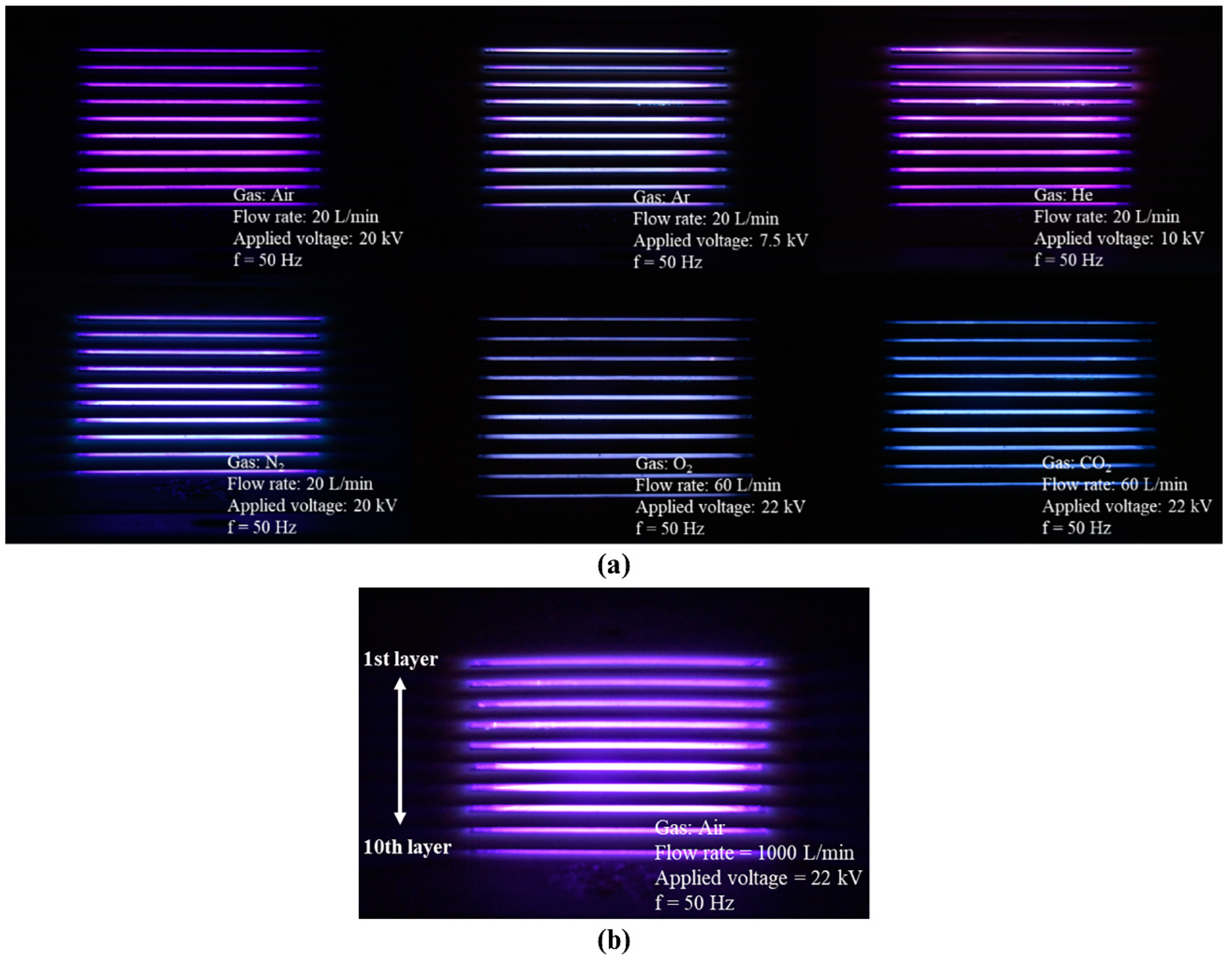
3.2. Multi-Gas Plasma Ignition

Based on the above results, a ten-layer DBD reactor, which includes a combination of an airflow diffuser and perforated metal plates, was fabricated and examined for plasma generation, which is one of the primary metrics that should be satisfied. The ten-layer DBD reactor was powered by a sinusoidal 50 Hz AC power source ranging between 0 and 22 kV. Figure 5a shows the plasmas successfully generated in the ten-layer DBD reactor using multiple gases (air, argon, helium, nitrogen, oxygen, and carbon dioxide) under the corresponding experimental conditions. This result suggests multiple potential applications for the ten-layer DBD reactor because the reactive species produced in the plasma vary with the ignited gas source [47,48]. Plasma generation at a high targeted flow rate (1000 L/min) was also investigated. As shown in Figure 5b, stable air-induced plasma ignition was observed in each flow channel of the ten-layer DBD reactor, confirming the rationality of the flow path design using CFD simulations and the effectiveness of the ten-layer DBD reactor at high flow rates for large-area plasma generation.

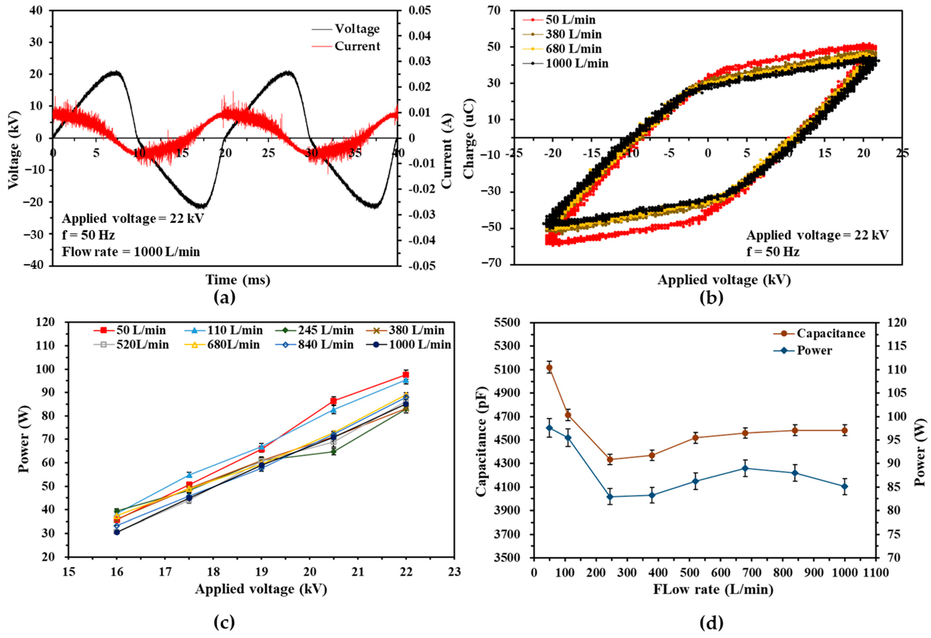
3.3. Electrical Characteristics at a High Flow Rates

In addition to the evaluation of multi-gas plasma generation, the electrical characteristics of the ten-layer DBD plasma were also investigated because energy consumption is a critical consideration in industrial applications. Figure 6a,b show the typical voltage and current waveforms and the Lissajous figure (i.e., Q–U characteristics) in the ten-layer DBD reactor during plasma discharge, where the applied voltage and working gas were set to 22 kV and air, respectively. As shown in Figure 6a, pulse current lines occur simultaneously with the ionization of the working gas when the applied voltage rises above a threshold (>16 kV in the ten-layer DBD reactor). The discharge frequency was dominated by that of the applied voltage, which was 50 Hz. Figure 6b presents the Q–U characteristics of the ten-layer DBD reactor, through which the power dissipated in the discharge was calculated. For example, when the applied voltage was fixed at 22 kV, the discharge power was 98 W at 50 L/min, 96 W at 110 L/min, and 85 W at 1000 L/min, respectively. In addition, the discharge power of the ten-layer DBD reactor (95.50 W at 110 L/min, 22 kV) is approximately 2.32 times larger than that of the two-layer DBD reactor (41.23 W at 110 L/min, 21.5 kV) as studied previously, which can be attributed to the larger discharge space of the ten-layer case (400 cm3), which is 2.22 times larger than that of the two-layer case (180 cm3); This is in good agreement with the power characteristics of two previously reported high-flow-rate DBD reactors [29].
A plot of the discharge power versus applied voltage is depicted in Figure 6c for the ten-layer DBD reactor, where the working gas was set to air, and the gas flow rate was varied from 50 to 1000 L/min. The discharge power of the ten-layer DBD reactor increased as the applied voltage increased, irrespective of changes in the gas flow rate. For example, at a flow rate of 1000 L/min, as the applied voltage increased from 16 kV to 22 kV, the discharge power rose from 31 W to 85 W. This indicated that the applied voltage played a beneficial role in determining the discharge power ( P ) since the discharge power is proportional to the maximum charge ( q m a x ) transferred through and the effective breakdown voltage ( V b ) across the discharge gap (i.e., P = 2 × V b × q m a x × f , where f denotes the frequency of the AC power source; q m a x = 2 C d V m a x V b 2 C g V b , where C d , C g , and V m a x represent the total dielectric capacitance, the gap capacitance, and the maximum of the applied voltage, respectively) [45,49,50]. On the other hand, a decrease in the discharge power was observed at higher gas flow rates (245–1000 L/min), as shown in Figure 6c. This result can be ascribed to the increased airflow, which minimizes the thermal effect caused by the plasma discharge, resulting in a lower relative permittivity of the dielectrics ( C d ) used in the ten-layer DBD reactor. The lower the relative permittivity of the dielectrics, the lower the maximum charge ( q m a x ) transferred through the discharge gap for the same applied voltage, resulting in a low discharge power [26,50]. This can also be observed in Figure 6b,d, where the relative permittivity of the dielectrics of the ten-layer DBD reactor first drops significantly from 5120 pF to 4333 pF as the gas flow rate increases from 50 L/min to 245 L/min, and then (>380 L/min) begins to fluctuate around a similar level of 4583 pF at an applied voltage of 22 kV.

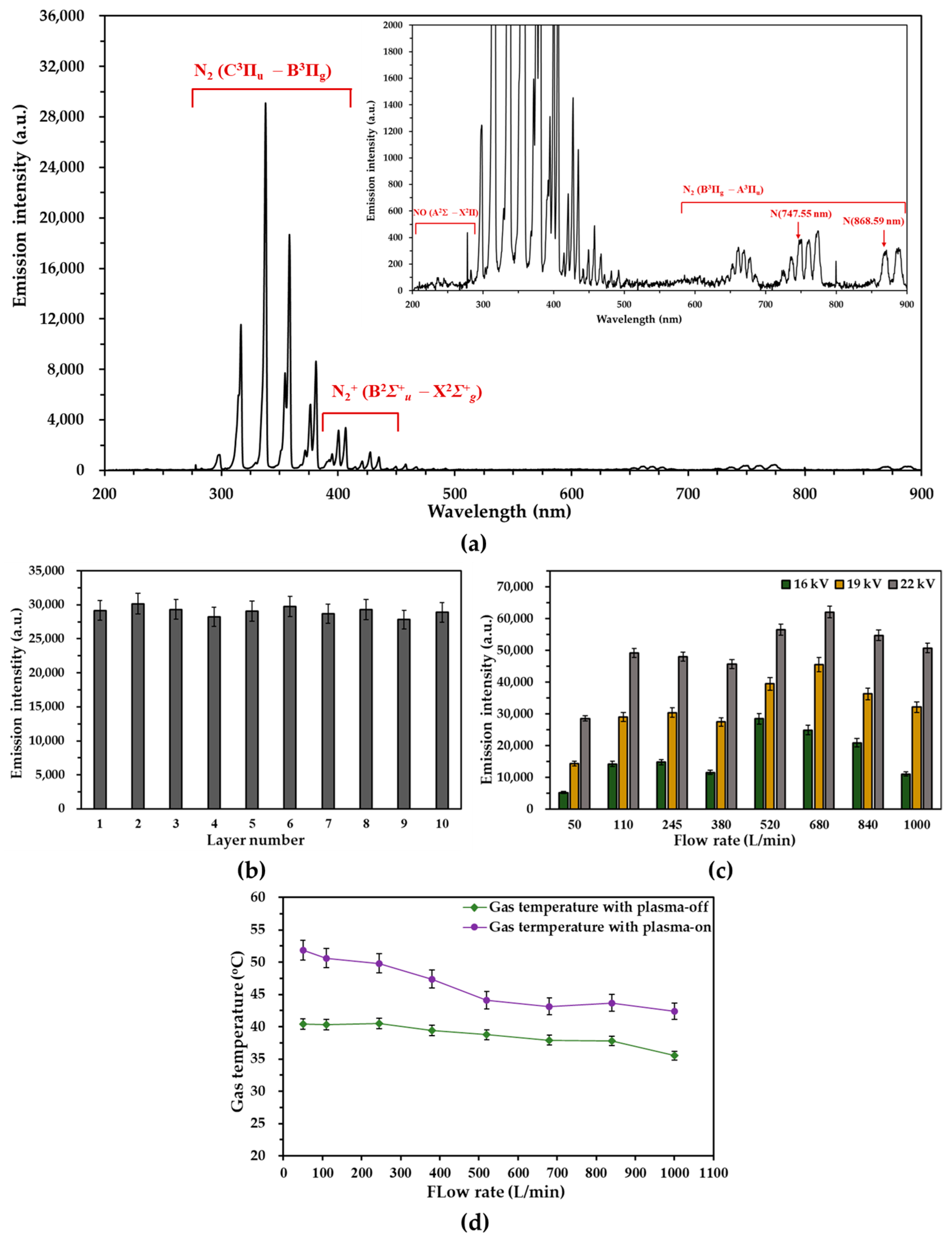
3.4. Spectroscopic Characteristics and Gas Temperature Measurement of the Air Plasma

As a powerful tool, OES is widely used to determine plasma properties, especially for studying excited and active species and excitation, vibrational, and rotational temperatures. In this study, OES was used to validate the uniformity of plasma generation in each channel of a ten-layer DBD reactor at a targeted high flow rate of 1000 L/min, and to confirm the optimum operating flow rate. The optical fiber was placed in the vicinity of each layer directly facing the plasma zone at the measurement points shown in Figure 3a, where it could detect the strongest emission intensity using careful and subtle adjustment. Figure 7a presents the optical emission spectrum in the range of 200–900 nm for the air discharge in the fifth flow channel of the DBD reactor, where the applied voltage and gas flow rate were fixed at 19 kV and 1000 L/min, respectively. It can be seen that the typical peak lines of the air plasma which mainly result from the excited N2 (i.e., N2 second positive band: N2 (C3Πu − B3Πg), N2+ first negative band: N2+ (B2Σ+u − X2Σ+g), and N2 first positive band: N2 (B3Πg − A3Πu)) were observed, as the main constituents of air are N2 (78.08%) and O2 (20.95%). Moreover, atomic nitrogen (N) at 747.55 nm and 868.55 nm were also determined. In contrast, only NO (A2Σ − X2Π) was detected in the O2-related lines, which may be due to the extremely strong emission intensity of the excited nitrogen species. These peak lines were identified by comparing them with references [51,52,53,54,55]. Moreover, the optical emission spectrum of each channel during the plasma discharge at 1000 L/min exhibited an extremely similar emission intensity under the same ignition conditions, with a standard deviation of the emission intensities in the 10 layers of 646, 2.22% of the average emission intensity (29,048). This confirms the uniformity of plasma generation in each layer, which is consistent with the results presented in Section 3.1, as depicted in Figure 7b.
The spectroscopic characteristics of the ten-layer DBD reactor were investigated with relation to the applied voltage and gas flow rate, with the integration time and average number of times set to be 3 s and 5, respectively. As shown in Figure 7c, for all gas flow rate cases, the increased voltage leads to a remarkably increased emission intensity at the 337.93 nm line of the fifth layer of the DBD reactor, which is due to the power deposited to discharge being enhanced by the increased voltage. In contrast, the emission intensity varied significantly from 26,602 to 62,073 at 22 kV as the gas flow rate increased from 50 to 1000 L/min. The 50 L/min case showed the lowest emission intensity at all applied voltages because the gas flowing with this low rate could not deliver sufficient atoms and molecules per unit time for ionization, resulting in the lowest emission intensity of 28,602 at 22 kV. However, as the gas flow rate increased from 110 to 380 L/min, the insufficiency of molecular delivery was slightly alleviated, leading to a relatively high emission intensity at 22 kV (49,164 at 110 L/min, 47,987 at 245 L/min, and 45,673 at 380 L/min). In contrast, at 520 and 680 L/min, the insufficiency of the molecular supply was further alleviated, resulting in an emission intensity peak at 62,073 at 680 L/min and 22 kV. This suggests that there is an optimum operating flow rate for the ten-layer DBD reactor. However, as the gas flow rate increased above 840 L/min, the emission intensity decreased because the excess molecule supply and rapidly decreasing transit time caused partial discharge in the plasma zone, resulting in a decrease in the emission intensity at 840 and 1000 L/min.
The gas temperature of the air plasma was evaluated with respect to the gas flow rate. The fiber-optic temperature probe was placed at the fifth layer of the ten-layer DBD reactor, and the gas temperatures of the plasma-off were recorded when the temperature reached a plateau (approximately 30 min after gas injection), while those of the plasma-on were recorded 10 min after plasma ignition. Figure 7d shows the gas temperature of the air plasma generated in the ten-layer DBD reactor as a function of the gas flow rate, where the applied voltage was fixed at 22 kV, and the initial gas temperature before plasma-on (i.e., gas temperature with plasma-off) varied from 35.5 °C at 1000 L/min to 40.43 °C at 50 L/min. The increase in the gas temperature after plasma-on ranged from a maximum of 11.42 °C at 50 L/min to a minimum of 5.23 °C at 680 L/min. As can be observed, all the gas temperatures of the plasma generated in the ten-layer DBD reactor, irrespective of the change in the gas flow rates, were maintained at a low temperature (42.41–51.85 °C), corroborating the generation of LTP. Moreover, the plasma gas temperature significantly dropped from 51.85 °C at 50 L/min to 44.12 °C at 520 L/min, and then gradually declined to 42.41 °C at 1000 L/min. This phenomenon can be attributed to the increased heating effect at lower flow rates, which is caused by the heated gate valve due to the collision of high-flow-rate wind induced on the primary side. And the increasing cooling effect at higher flow rates can alleviate the heating effect resulting from both the heated gate valve and the plasma discharge, as demonstrated in Section 3.3 [26,56]. This result is also in excellent agreement with the finding that higher temperatures at lower gas flow rates increase the relative permittivity of the dielectrics of the ten-layer DBD reactor.

4. Conclusions

In this study, an upscaled, high-flow-rate, ten-layer DBD reactor, capable of treating gas at a flow rate of 1000 L/min, was designed and fabricated for high-flow-rate gas treatment, especially for controlling indoor air quality. The design methodology for developing high-flow-rate DBD reactors, including CFD simulations, flow path optimization via practical and OES measurements, and electrical and spectroscopic characterizations, provided fundamental knowledge for the real-life application of DBD technologies, especially for environmental protection (exhaust purification, outdoor and indoor air pollution mitigation, wastewater treatment, CO2 reduction, etc.). Notably, both the CFD simulations and practical velocity measurements confirmed remarkable improvement in the airflow uniformity in the multilayer DBD configuration owing to the incorporated airflow diffuser and perforated plates. The velocity uniformity in the ten-layer DBD reactor was significantly improved from 1.38 m/s to 0.13 m/s, considering the standard deviation of the ten flow channels in the practical measurements. Moreover, multi-gas (air, Ar, He, N2, O2, and CO2) plasma ignition and high-flow-rate plasma generation of up to 1000 L/min were achieved with the upscaled ten-layer DBD reactor, and this observation validated its effectiveness under multi-gas conditions and at high flow rates. Furthermore, spectroscopic characterization and gas temperature evaluation of the air plasma at high flow rates were also carried out, which confirmed that the optimum working flow rate was 680 L/min (in terms of emission intensity), and the gas temperature at the plasma-on condition was maintained at (low values) 51.85 and 42.41 °C at 50 and 1000 L/min, respectively.
However, the treatment characteristics and performance of the ten-layer DBD reactor for indoor air pollutants, such as VOCs, were not investigated in this study. Future investigations will be focused on the characterization of VOC decomposition, such as toluene treatment, along with by-product analysis for environmental risk assessment and the decomposition of multiple VOCs or their mixtures for further refinement of high-flow-rate DBD reactors.

Author Contributions

Conceptualization, M.X., Y.M., Z.L., Y.F., Y.S., T.Z. and A.O.; methodology, M.X., Y.M., Y.F., T.Z., Y.S. and Z.L.; validation, M.X., Y.F. and Z.L.; formal analysis, M.X.; investigation, M.X., Y.F. and Z.L.; resources, M.X., Y.F., T.Z., Z.L. and A.O.; data curation, M.X., Y.F. and Z.L.; writing—original draft preparation, M.X.; writing—review and editing, M.X., Y.M., Z.L., Y.F., Y.S., T.Z. and A.O.; visualization, M.X.; supervision, A.O.; project administration, A.O.; funding acquisition, M.X. and A.O. All authors have read and agreed to the published version of the manuscript.

Funding

This work was supported in part by JST SPRING, grant number JPMJSP2106, and by the Cooperative Research Project of the Research Center for Biomedical Engineering.

Institutional Review Board Statement

Not applicable.

Informed Consent Statement

Not applicable.

Data Availability Statement

The data presented in this study are available in the article.

Conflicts of Interest

The authors declare no conflict of interest.

References

  1. Lelieveld, J.; Pozzer, A.; Pöschl, U.; Fnais, M.; Haines, A.; Münzel, T. Loss of life expectancy from air pollution compared to other risk factors: A worldwide perspective. Cardiovasc. Res. 2020, 116, 1910–1917. [Google Scholar] [CrossRef] [PubMed]
  2. González-Martín, J.; Kraakman, N.J.R.; Pérez, C.; Lebrero, R.; Muñoz, R. A state-of-the-art review on indoor air pollution and strategies for indoor air pollution control. Chemosphere 2021, 262, 128376. [Google Scholar] [CrossRef] [PubMed]
  3. Lu, X.; Naidis, G.V.; Laroussi, M.; Reuter, S.; Graves, D.B.; Ostrikov, K. Reactive species in non-equilibrium atmospheric-pressure plasmas: Generation, transport, and biological effects. Phys. Rep. 2016, 630, 1–84. [Google Scholar] [CrossRef]
  4. Laroussi, M. Low temperature plasma-based sterilization: Overview and state-of-the-art. Plasma Process. Polym. 2005, 2, 391–400. [Google Scholar] [CrossRef]
  5. Zhao, Y.; Xia, Y.; Xi, T.; Zhu, D.; Zhang, Q.; Qi, Z.; Liu, D.; Wang, W. Control of pathogenic bacteria on the surface of rolling fruits by an atmospheric pressure air dielectric barrier discharge system. J. Phys. D Appl. Phys. 2020, 53, 164005. [Google Scholar] [CrossRef]
  6. Sakudo, A.; Yagyu, Y.; Onodera, T. Disinfection and Sterilization Using Plasma Technology: Fundamentals and Future Perspectives for Biological Applications. Int. J. Mol. Sci. 2019, 20, 5216. [Google Scholar] [CrossRef]
  7. Kurosawa, M.; Takamatsu, T.; Kawano, H.; Hayashi, Y.; Miyahara, H.; Ota, S.; Okino, A.; Yoshida, M. Endoscopic Hemostasis in Porcine Gastrointestinal Tract Using CO2 Low-Temperature Plasma Jet. J. Surg. Res. 2019, 234, 334–342. [Google Scholar] [CrossRef]
  8. Gao, L.; Shi, X.; Wu, X. Applications and challenges of low temperature plasma in pharmaceutical field. J. Pharm. Anal. 2021, 11, 28–36. [Google Scholar] [CrossRef]
  9. Laroussi, M. Cold Plasma in Medicine and Healthcare: The New Frontier in Low Temperature Plasma Applications. Front. Phys. 2020, 8, 74. [Google Scholar] [CrossRef]
  10. Aida, M.; Iwai, T.; Okamoto, Y.; Miyahara, H.; Seto, Y.; Okino, A. Development of an ionization method using hydrogenated plasma for mass analysis of surface adhesive compounds. J. Anal. At. Spectrom. 2018, 33, 578–584. [Google Scholar] [CrossRef]
  11. Spencer, S.E.; Tyler, C.A.; Tolocka, M.P.; Glish, G.L. Low-temperature plasma ionization-mass spectrometry for the analysis of compounds in organic aerosol particles. Anal. Chem. 2015, 87, 2249–2254. [Google Scholar] [CrossRef] [PubMed]
  12. Foest, R.; Schmidt, M.; Becker, K. Microplasmas, an emerging field of low-temperature plasma science and technology. Int. J. Mass Spectrom. 2006, 248, 87–102. [Google Scholar] [CrossRef]
  13. Uricchio, A.; Fanelli, F. Low-Temperature Atmospheric Pressure Plasma Processes for the Deposition of Nanocomposite Coatings. Processes 2021, 9, 2069. [Google Scholar] [CrossRef]
  14. Sharma, A.; Verheijen, M.A.; Wu, L.; Karwal, S.; Vandalon, V.; Knoops, H.C.M.; Sundaram, R.S.; Hofmann, J.P.; Kessels, W.M.M.E.; Bol, A.A. Low-temperature plasma-enhanced atomic layer deposition of 2-D MoS2: Large area, thickness control and tuneable morphology. Nanoscale 2018, 10, 8615–8627. [Google Scholar] [CrossRef]
  15. Iwai, T.; Inoue, H.; Kakegawa, K.; Ohrui, Y.; Nagoya, T.; Nagashima, H.; Miyahara, H.; Chiba, K.; Seto, Y.; Okino, A. Development of a High-Efficiency Decomposition Technology for Volatile Chemical Warfare Agent Sarin Using Dielectric Barrier Discharge. Plasma Chem. Plasma Process. 2020, 40, 907–920. [Google Scholar] [CrossRef]
  16. Vandenbroucke, A.M.; Morent, R.; De Geyter, N.; Leys, C. Non-thermal plasmas for non-catalytic and catalytic VOC abatement. J. Hazard. Mater. 2011, 195, 30–54. [Google Scholar] [CrossRef]
  17. Li, S.; Ma, X.; Jiang, Y.; Cao, X. Acetamiprid removal in wastewater by the low-temperature plasma using dielectric barrier discharge. Ecotoxicol. Environ. Saf. 2014, 106, 146–153. [Google Scholar] [CrossRef]
  18. Yanagawa, Y.; Kawano, H.; Kobayashi, T.; Miyahara, H.; Okino, A.; Mitsuhara, I. Direct protein introduction into plant cells using a multi-gas plasma jet. PLoS ONE 2017, 12, e0171942. [Google Scholar] [CrossRef]
  19. Liao, X.; Bai, Y.; Muhammad, A.I.; Liu, D.; Hu, Y.; Ding, T. The application of plasma-activated water combined with mild heat for the decontamination of Bacillus cereus spores in rice (Oryza sativa L. ssp. japonica). J. Phys. D Appl. Phys. 2019, 53, 064003. [Google Scholar] [CrossRef]
  20. Ambrico, P.F.; Šimek, M.; Ambrico, M.; Morano, M.; Prukner, V.; Minafra, A.; Allegretta, I.; Porfido, C.; Senesi, G.S.; Terzano, R. On the air atmospheric pressure plasma treatment effect on the physiology, germination and seedlings of basil seeds. J. Phys. D Appl. Phys. 2019, 53, 104001. [Google Scholar] [CrossRef]
  21. Černáková, L.; Kováčik, D.; Zahoranová, A.; Černák, M.; Mazúr, M. Surface Modification of Polypropylene Non-Woven Fabrics by Atmospheric-Pressure Plasma Activation Followed by Acrylic Acid Grafting. Plasma Chem. Plasma Process. 2005, 25, 427–437. [Google Scholar] [CrossRef]
  22. Liu, R.; Li, X.; Hu, X.; Dong, H. Surface modification of a medical grade Co-Cr-Mo alloy by low-temperature plasma surface alloying with nitrogen and carbon. Surf. Coat. Technol. 2013, 232, 906–911. [Google Scholar] [CrossRef]
  23. Lu, W.; Abbas, Y.; Mustafa, M.F.; Pan, C.; Wang, H. A review on application of dielectric barrier discharge plasma technology on the abatement of volatile organic compounds. Front. Environ. Sci. Eng. China 2019, 13, 30. [Google Scholar] [CrossRef]
  24. Chang, C.-L.; Lin, T.-S. Decomposition of Toluene and Acetone in Packed Dielectric Barrier Discharge Reactors. Plasma Chem. Plasma Process. 2005, 25, 227–243. [Google Scholar] [CrossRef]
  25. Saleem, F.; Rehman, A.; Ahmad, F.; Khoja, A.H.; Javed, F.; Zhang, K.; Harvey, A. Removal of toluene as a toxic VOC from methane gas using a non-thermal plasma dielectric barrier discharge reactor. RSC Adv. 2021, 11, 27583–27588. [Google Scholar] [CrossRef] [PubMed]
  26. Wang, J.; Cheng, S.; Liu, N.; Lu, N.; Shang, K.; Jiang, N.; Li, J.; Wu, Y. Degradation of toluene by tube-tube coaxial dielectric barrier discharge: Power characteristics and power factor optimization. Environ. Technol. 2023, 44, 897–910. [Google Scholar] [CrossRef]
  27. Guo, Y.; Ye, D.; Chen, K.; He, J. Toluene removal by a DBD-type plasma combined with metal oxides catalysts supported by nickel foam. Catal. Today 2007, 126, 328–337. [Google Scholar] [CrossRef]
  28. Lee, J.E.; Ok, Y.S.; Tsang, D.C.W.; Song, J.; Jung, S.-C.; Park, Y.-K. Recent advances in volatile organic compounds abatement by catalysis and catalytic hybrid processes: A critical review. Sci. Total Environ. 2020, 719, 137405. [Google Scholar] [CrossRef]
  29. Xu, M.; Fukuyama, Y.; Nakai, K.; Liu, Z.; Sumiya, Y.; Okino, A. Characteristics of Double-Layer, Large-Flow Dielectric Barrier Discharge Plasma Source for Toluene Decomposition. Plasma 2023, 6, 212–224. [Google Scholar] [CrossRef]
  30. Schiavon, M.; Torretta, V.; Casazza, A.; Ragazzi, M. Non-thermal Plasma as an Innovative Option for the Abatement of Volatile Organic Compounds: A Review. Water Air Soil Pollut. Focus 2017, 228, 388. [Google Scholar] [CrossRef]
  31. Li, J.; Ma, C.; Zhu, S.; Yu, F.; Dai, B.; Yang, D. A Review of Recent Advances of Dielectric Barrier Discharge Plasma in Catalysis. Nanomaterials 2019, 9, 1428. [Google Scholar] [CrossRef] [PubMed]
  32. Dobslaw, D.; Schulz, A.; Helbich, S.; Dobslaw, C.; Engesser, K.-H. VOC removal and odor abatement by a low-cost plasma enhanced biotrickling filter process. J. Environ. Chem. Eng. 2017, 5, 5501–5511. [Google Scholar] [CrossRef]
  33. Brandenburg, R. Dielectric barrier discharges: Progress on plasma sources and on the understanding of regimes and single filaments. Plasma Sources Sci. Technol. 2017, 26, 053001. [Google Scholar] [CrossRef]
  34. Müller, S.; Zahn, R.-J. Air pollution control by non-thermal plasma. Contrib. Plasma Phys. 2007, 47, 520–529. [Google Scholar] [CrossRef]
  35. Matyakubov, N.; Nguyen, D.B.; Saud, S.; Heo, I.; Kim, S.-J.; Kim, Y.J.; Lee, J.H.; Mok, Y.S. Effective practical removal of acetaldehyde by a sandwich-type plasma-in-honeycomb reactor under surrounding ambient conditions. J. Hazard. Mater. 2021, 415, 125608. [Google Scholar] [CrossRef] [PubMed]
  36. Nguyen, D.B.; Shirjana, S.; Hossain, M.M.; Heo, I.; Mok, Y.S. Effective generation of atmospheric pressure plasma in a sandwich-type honeycomb monolith reactor by humidity control. Chem. Eng. J. 2020, 401, 125970. [Google Scholar] [CrossRef]
  37. Jo, J.-O.; Lee, S.B.; Jang, D.L.; Mok, Y.S. Plasma–Catalytic Ceramic Membrane Reactor for Volatile Organic Compound Control. IEEE Trans. Plasma Sci. IEEE Nucl. Plasma Sci. Soc. 2013, 41, 3021–3029. [Google Scholar] [CrossRef]
  38. Saud, S.; Bhattarai, R.M.; Nguyen, D.B.; Neupane, S.; Matyakubov, N.; Lee, B.; Kim, Y.J.; Lee, J.H.; Heo, I.; Mok, Y.S. A comprehensive study on scaling up ethylene abatement via intermittent plasma-catalytic discharge process in a novel reactor configuration comprising multiple honeycomb monoliths. Chem. Eng. J. 2023, 454, 140486. [Google Scholar] [CrossRef]
  39. Wright, A.; Taglioli, M.; Montazersadgh, F.; Shaw, A.; Hemaka Bandulasena, H.C. Microbubble-Enhanced DBD Plasma Reactor: Design, Characterisation and Modelling. Chem. Eng. Res. Des. 2019, 144, 159–173. [Google Scholar] [CrossRef]
  40. Suenaga, Y.; Takamatsu, T.; Aizawa, T.; Moriya, S.; Matsumura, Y.; Iwasawa, A.; Okino, A. Plasma Gas Temperature Control Performance of Metal 3D-Printed Multi-Gas Temperature-Controllable Plasma Jet. Appl. Sci. 2021, 11, 11686. [Google Scholar] [CrossRef]
  41. Onyshchenko, I.; De Geyter, N.; Morent, R. Improvement of the plasma treatment effect on PET with a newly designed atmospheric pressure plasma jet. Plasma Process. Polym. 2017, 14, 1600200. [Google Scholar] [CrossRef]
  42. Pasolari, R.S.; Papadopoulos, P.K.; Svarnas, P.; Giannakopoulos, E.; Krontiras, C. Macroscopic modeling of plasma effects on heat and fluid flow in a dielectric barrier discharge based process for biosolid stabilization. AIP Adv. 2020, 10, 045021. [Google Scholar] [CrossRef]
  43. Abdulkadirov, R.; Lyakhov, P. Estimates of Mild Solutions of Navier–Stokes Equations in Weak Herz-Type Besov–Morrey Spaces. Sci. China Ser. A Math. 2022, 10, 680. [Google Scholar] [CrossRef]
  44. Mei, D.; Zhu, X.; He, Y.; Yan, J.D.; Tu, X. Plasma-assisted conversion of CO2 in a dielectric barrier discharge reactor: Understanding the effect of packing materials. Plasma Sources Sci. Technol. 2015, 24, 015011. [Google Scholar] [CrossRef]
  45. Tu, X.; Gallon, H.J.; Twigg, M.V.; Gorry, P.A.; Christopher Whitehead, J. Dry reforming of methane over a Ni/Al2O3 catalyst in a coaxial dielectric barrier discharge reactor. J. Phys. D Appl. Phys. 2011, 44, 274007. [Google Scholar] [CrossRef]
  46. Mahammadunnisa, S.; Reddy, E.L.; Reddy, P.R.M.K.; Subrahmanyam, C. A facile approach for direct decomposition of nitrous oxide assisted by non-thermal plasma. Plasma Process. Polym. 2013, 10, 444–450. [Google Scholar] [CrossRef]
  47. Suenaga, Y.; Takamatsu, T.; Aizawa, T.; Moriya, S.; Matsumura, Y.; Iwasawa, A.; Okino, A. Influence of Controlling Plasma Gas Species and Temperature on Reactive Species and Bactericidal Effect of the Plasma. Appl. Sci. 2021, 11, 11674. [Google Scholar] [CrossRef]
  48. Wagner, H.-E.; Brandenburg, R.; Kozlov, K.V.; Sonnenfeld, A.; Michel, P.; Behnke, J.F. The barrier discharge: Basic properties and applications to surface treatment. Vacuum 2003, 71, 417–436. [Google Scholar] [CrossRef]
  49. Pipa, A.V.; Koskulics, J.; Brandenburg, R.; Hoder, T. The simplest equivalent circuit of a pulsed dielectric barrier discharge and the determination of the gas gap charge transfer. Rev. Sci. Instrum. 2012, 83, 115112. [Google Scholar] [CrossRef]
  50. Pipa, A.V.; Hoder, T.; Koskulics, J.; Schmidt, M.; Brandenburg, R. Experimental determination of dielectric barrier discharge capacitance. Rev. Sci. Instrum. 2012, 83, 075111. [Google Scholar] [CrossRef]
  51. Stancu, G.D.; Kaddouri, F.; Lacoste, D.A.; Laux, C.O. Atmospheric pressure plasma diagnostics by OES, CRDS and TALIF. J. Phys. D Appl. Phys. 2010, 43, 124002. [Google Scholar] [CrossRef]
  52. Walsh, J.L.; Kong, M.G. Portable nanosecond pulsed air plasma jet. Appl. Phys. Lett. 2011, 99, 081501. [Google Scholar] [CrossRef]
  53. Deng, X.L.; Nikiforov, A.Y.; Vanraes, P.; Leys, C. Direct current plasma jet at atmospheric pressure operating in nitrogen and air. J. Appl. Phys. 2013, 113, 023305. [Google Scholar] [CrossRef]
  54. Yue, W.; Lei, W.; Dong, Y.; Shi, C.; Lu, Q.; Cui, X.; Wang, X.; Chen, Y.; Zhang, J. Toluene degradation in air/H2O DBD plasma: A reaction mechanism investigation based on detailed kinetic modeling and emission spectrum analysis. J. Hazard. Mater. 2023, 448, 130894. [Google Scholar] [CrossRef]
  55. Xiao, D.; Cheng, C.; Shen, J.; Lan, Y.; Xie, H.; Shu, X.; Meng, Y.; Li, J.; Chu, P.K. Characteristics of atmospheric-pressure non-thermal N2 and N2/O2 gas mixture plasma jet. J. Appl. Phys. 2014, 115, 033303. [Google Scholar] [CrossRef]
  56. Butterworth, T.; Allen, R.W.K. Plasma-catalyst interaction studied in a single pellet DBD reactor: Dielectric constant effect on plasma dynamics. Plasma Sources Sci. Technol. 2017, 26, 065008. [Google Scholar] [CrossRef]
Figure 1. Design schemes of the ten-layer DBD reactor: (a) schematic of the ten-layered gas treatment part (ten-layer DBD cascade); (b) overall and cross-sectional views of the complete configuration of the ten-layer DBD reactor.
Applsci 14 00027 g001
Figure 2. Schematic of the experimental setup used for the electrical and spectroscopic characterizations.
Applsci 14 00027 g002
Figure 3. (a) Measurement points in CFD (upper right) and for practical velocity measurements (lower right); the flow vector profiles at the fifth layer (middle left) and flow velocity per channel (middle right) of the three simulation models of the ten-layer DBD reactor: (b) None, (c) airflow diffuser, and (d) airflow diffuser + perforated metal.
Applsci 14 00027 g003
Figure 4. (a) Flow velocity and (b) retention time per channel of the three patterns (none, airflow diffuser, airflow diffuser + perforated metal).
Applsci 14 00027 g004
Figure 5. (a) Generation of plasma with multiple gases (air, Ar, He, N2, O2, and CO2); (b) air plasma ignited at a high flow rate of 1000 L/min.
Applsci 14 00027 g005
Figure 6. (a) Typical voltage and current waveforms and (b) Q–U Lissajous figures of the ten-layer DBD reactor at 22 kV; (c) power consumption as a function of applied voltage at different gas flow rates (air); and (d) plot of capacitances during plasma discharge versus flow rate for the ten-layer DBD reactor.
Applsci 14 00027 g006
Figure 7. (a) Optical emission spectrum of the air plasma discharge at the fifth layer and (b) emission intensities at the 337.93 nm line in each flow channel of the ten-layer DBD reactor, ignited at 19 kV and 1000 L/min; (c) emission intensities at the 337.93 nm line of the air plasma discharge in the fifth channel at different gas flow rates; (d) gas temperature of the air plasma as a function of gas flow rate at 22 kV.
Applsci 14 00027 g007
Table 1. Information on the meshing of the three models.
ModelMesh ElementFluid NodeSolid NodeTotal Node
NoneTetrahedral126,86581,699208,564
Airflow diffuserTetrahedral127,75682,275210,031
Airflow diffuser + perforated metalTetrahedral216,88185,611302,492
Disclaimer/Publisher’s Note: The statements, opinions and data contained in all publications are solely those of the individual author(s) and contributor(s) and not of MDPI and/or the editor(s). MDPI and/or the editor(s) disclaim responsibility for any injury to people or property resulting from any ideas, methods, instructions or products referred to in the content.

