

A Novel Passive Implantable Differential Mechanism to Restore Individuated Finger Flexion during Grasping following Tendon Transfer Surgery: A Pilot Study
 , , , , , , and
Abstract
1. Introduction
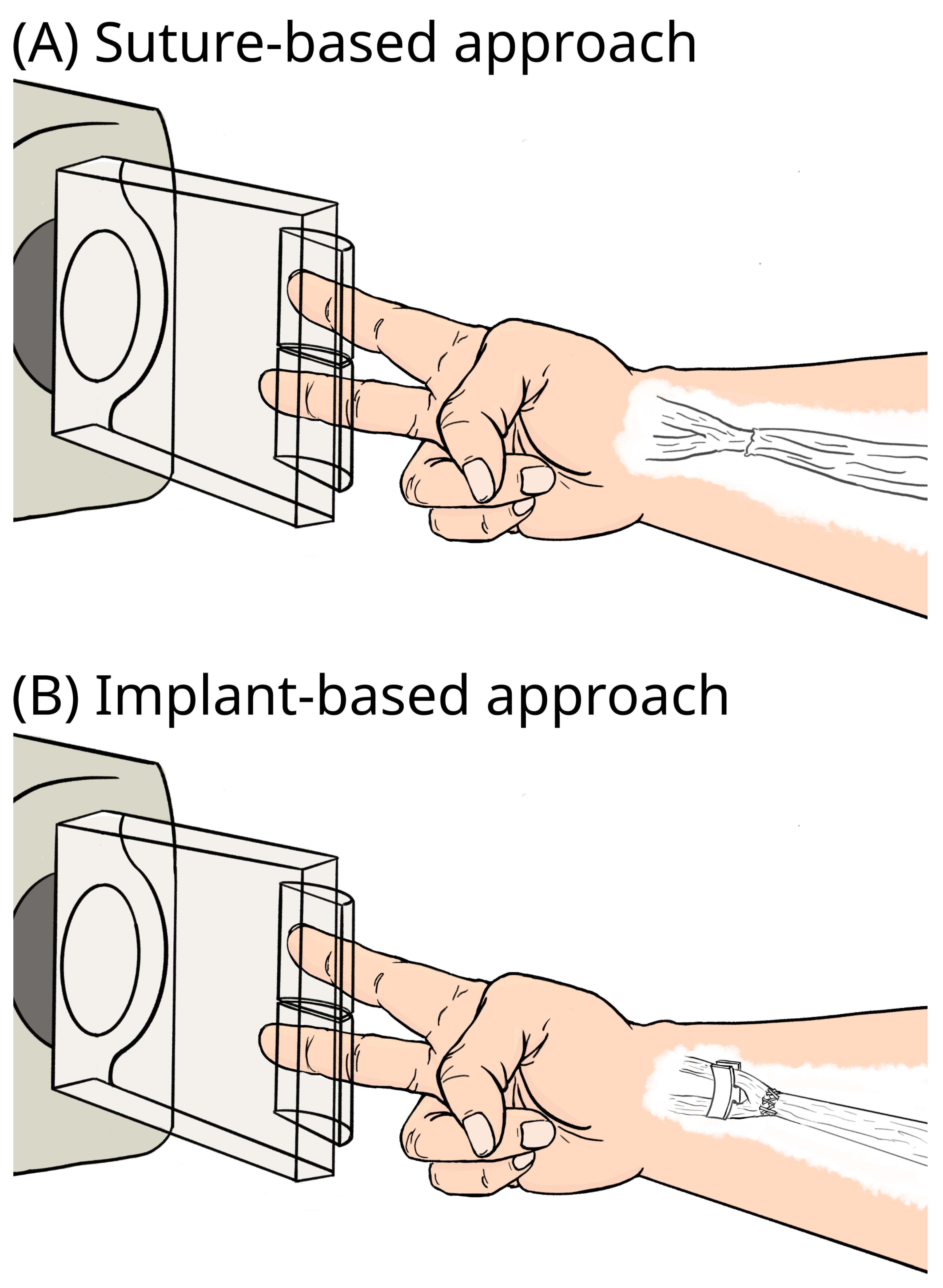
2. Materials and Methods
2.1. Cadaver Preparation with Implants
2.2. Actuation and Sensing
2.3. Testing Protocol
- Rod implant (short tendon triangle)—free moving.
- Rod implant (tall tendon triangle)
- −
- Free moving
- −
- Glued to surrounding tissue to simulate postoperative scarring.
- U implant
- −
- Free moving
- −
- Glued to surrounding tissue to simulate postoperative scarring.
- Baseline suture approach—free moving.
3. Results
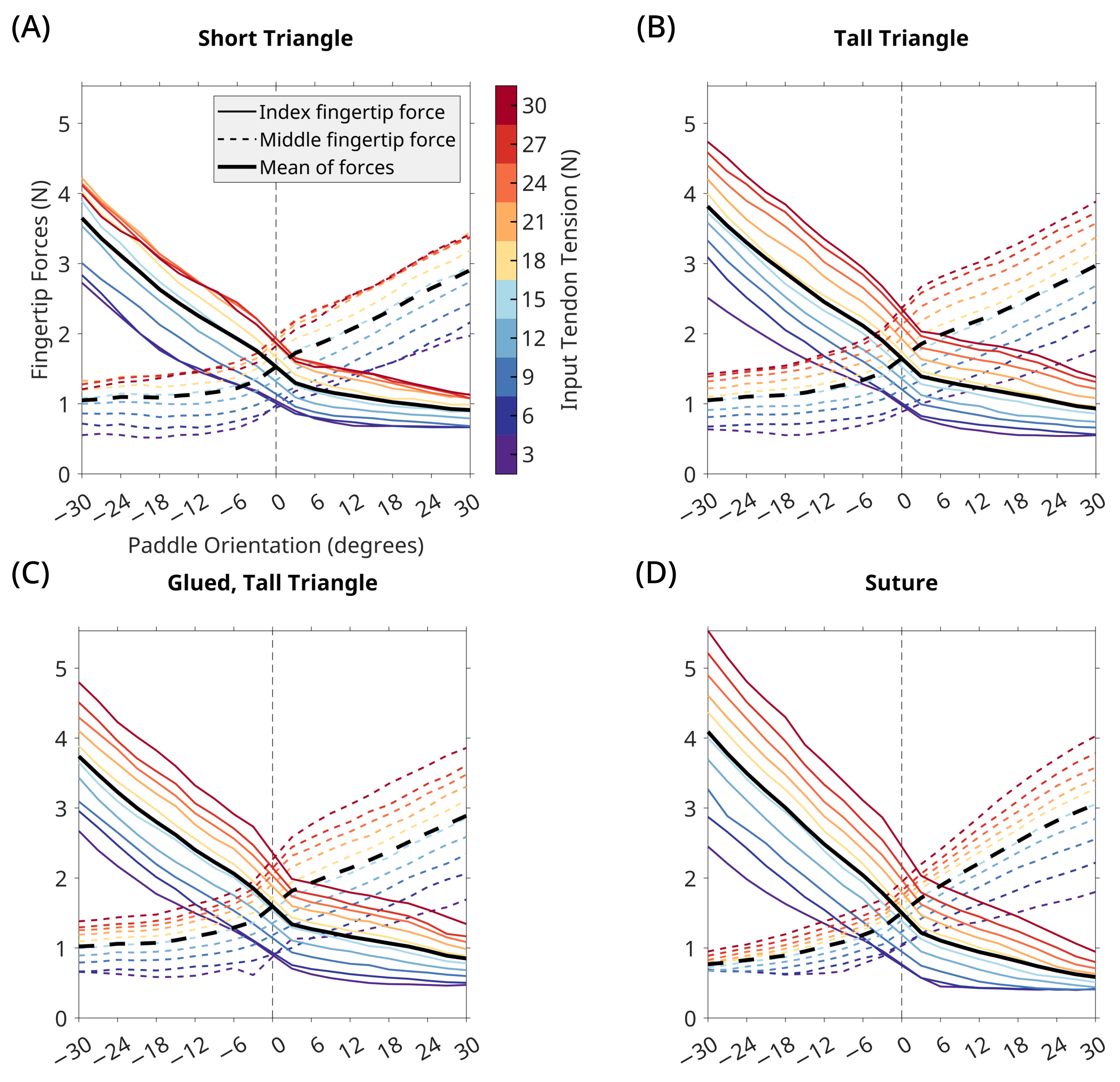
3.1. Rod Implant

| Configuration | Average Difference in Fingertip Forces (Lower MAE Is Better) | Variation in Fingertip Force Differences Due to Input Tendon Tension (Lower MAE Is Better) | Paddle Orientations for Which Implant Outperforms Baseline (p-Value < 0.05%) |
|---|---|---|---|
| Rod implant | |||
| short triangle | |||
| tall triangle | |||
| glued tall triangle | |||
| baseline suture |  (1.75N MAE) (1.75N MAE) | (2.32N MAE) |  |
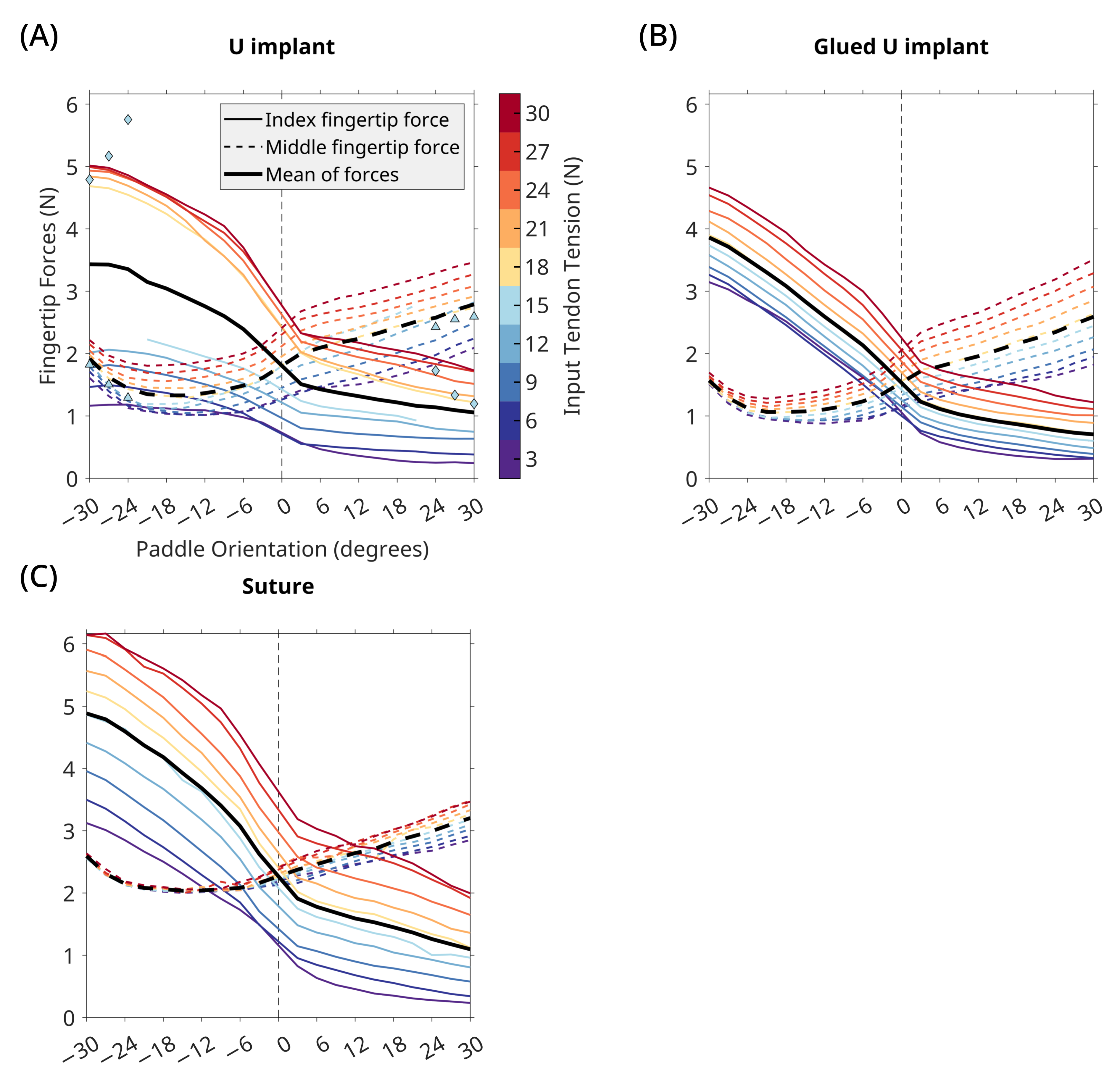
| U implant | |||
| U implant | |||
| glued U implant | | ||
| baseline suture | (1.59N MAE) | (2.11N MAE) | |
3.2. U Implant
4. Discussion
4.1. Implant Performance
4.2. Surgical Considerations
4.3. Inspiration from the Engineering Domain and Animal Models
4.4. Implant Design and Fabrication
4.5. Considerations When Using Fresh-Frozen Cadaver Specimens
4.6. Tissue Abrasion and Foreign Body Response
4.7. Study Limitations
Author Contributions
Funding
Data Availability Statement
Acknowledgments
Conflicts of Interest
Abbreviations
| DC | Direct Current |
| ECRL | Extensor Carpi Radialis Longus |
| EDC | Extensor Digitorum Communis |
| EIP | Extensor Indicis Proprius |
| FDA | Food and Drug Administration |
| FDP | Flexor Digitorum Profundus |
| FDS | Flexor Digitorum Superficialis |
| FPL | Flexor Pollicis Longus |
| MAE | Mean Absolute Error |
| NI | National Instruments |
| RPU | Rigid Polyurethane |
References
- Seiler, J.G.; Desai, M.J.; Payne, H.S. Tendon Transfers for Radial, Median, and Ulnar Nerve Palsy. J. Am. Acad. Orthop. Surg. 2013, 21, 675–684. [Google Scholar] [CrossRef] [PubMed]
- Sammer, D.M.; Chung, K.C. Tendon Transfers: Part II. Transfers for Ulnar Nerve Palsy and Median Nerve Palsy. Plastic Reconstr. Surg. 2009, 124, 212e–221e. [Google Scholar] [CrossRef]
- Cooney, W.P. Tendon transfer for median nerve palsy. Hand Clin. 1988, 4, 155–165. [Google Scholar] [CrossRef] [PubMed]
- Riordan, D.C. Tendon Transfers for Median, Ulnar or Radial Nerve Palsy. Hand 1969, 1, 42–46. [Google Scholar] [CrossRef]
- Burkhalter, W.E. Early tendon transfer in upper extremity peripheral nerve injury. Clin. Orthop. Relat. Res.® 1974, 104, 68–79. [Google Scholar] [CrossRef]
- Montgomery, J.; Balasubramanian, R.; Mardula, K.L.; Allan, C.H. New Tendon-Transfer Surgery for Ulnar-Median Nerve Palsy Using Embedded Adaptive Engineering Mechanisms. In Proceedings of the 11th International Symposium, Computer Methods in Biomechanics and Biomedical Engineering, Salt Lake City, UT, USA, 3–6 April 2013; pp. 11–12. [Google Scholar]
- Gray, K.; Meals, R.A. Beasley’s surgery of the hand: Robert W. Beasley. New York; Thieme Medical Publishers, 2003, 531 pages, $199.00. J. Hand Surg. 2004, 29, 336. [Google Scholar] [CrossRef]
- Wangdell, J.; Bunketorp-Käll, L.; Koch-Borner, S.; Fridén, J. Early Active Rehabilitation After Grip Reconstructive Surgery in Tetraplegia. Arch. Phys. Med. Rehabil. 2016, 97, S117–S125. [Google Scholar] [CrossRef]
- Balasubramanian, R.; Homayouni, T.; Valero-Cuevas, F. Implanted Passive Engineering Mechanisms and Methods for their Use and Manufacture. U.S. Patent 9,925,035, 27 May 2018. [Google Scholar]
- Balasubramanian, R.; Homayouni, T.; Valero-Cuevas, F. Implanted Passive Engineering Mechanisms and Methods for their Use and Manufacture. U.S. Patent 10,595,984, 24 May 2020. [Google Scholar]
- Mardula, K.L.; Balasubramanian, R.; Allan, C.H. Implanted passive engineering mechanism improves hand function after tendon transfer surgery: A cadaver-based study. Hand 2015, 10, 116–122. [Google Scholar] [CrossRef]
- Carbon3D. Carbon3D Rigid Polyurethane (RPU 70). 2022. Available online: https://carbon3d.com/materials/rpu-70/ (accessed on 14 December 2022).
- Hand Biomechanics Lab. Agee-WristJack Surgeon’s Manual. 2002. Available online: https://handbiolab.com/wp-content/uploads/2017/09/WJSM-306000R.pdf (accessed on 14 December 2022).
- Hand Biomechanics Lab. Agee-WristJack. 2022. Available online: https://handbiolab.com/products/wristjack/ (accessed on 14 December 2022).
- McMaster-Carr. High-Strength High-Temperature Para-Aramid Thread: 0.038" Diameter—Mcmaster Carr Part #8800K43. 2022. Available online: https://www.mcmaster.com/8800K43/ (accessed on 14 December 2022).
- Jalaleddini, K.; Minos Niu, C.; Chakravarthi Raja, S.; Joon Sohn, W.; Loeb, G.E.; Sanger, T.D.; Valero-Cuevas, F.J. Neuromorphic meets neuromechanics, part II: The role of fusimotor drive. J. Neural Eng. 2017, 14, 025002. [Google Scholar] [CrossRef]
- Niu, C.M.; Jalaleddini, K.; Sohn, W.J.; Rocamora, J.; Sanger, T.D.; Valero-Cuevas, F.J. Neuromorphic meets Neuromechanics PART I: The Methodology and Implementation. J. Neural Eng. 2017, 14, 025001. [Google Scholar] [CrossRef]
- Adept Technology Inc. AdeptSix 300 Instruction Handbook; Data Sheet 00660–00100; Regional Headquarter Omron Adept: San Eamon, CA, USA, 2005. [Google Scholar]
- Johanson, M.E.; Smaby, N.; Murray, W.M.; Hentz, V.R. The effect of task demand on pinch force magnitude in subjects with spinal cord injury. J. Neurol. Phys. Ther. 2007, 31, 197–198. [Google Scholar]
- Johanson, M.E.; Murray, W.M. The unoperated hand: The role of passive forces in hand function after tetraplegia. Hand Clin. 2002, 18, 391–398. [Google Scholar] [CrossRef]
- Mehta, V.; Phillips, C.S. Flexor Tendon Pulley Reconstruction. Hand Clin. 2005, 21, 245–251. [Google Scholar] [CrossRef]
- Uchiyama, S.; Coert, J.H.; Berglund, L.; Amadio, P.C.; An, K.N. Method for the measurement of friction between tendon and pulley. J. Orthop. Res. 1995, 13, 83–89. [Google Scholar] [CrossRef] [PubMed]
- Petersen, W.; Stein, V.; Bobka, T. Structure of the human tibialis anterior tendon. J. Anat. 2000, 197, 617–625. [Google Scholar] [CrossRef] [PubMed]
- Lee, D.H.; Oakes, J.E.; Ferlic, R.J. Tendon transfers for thumb opposition: A biomechanical study of pulley location and two insertion sites. J. Hand Surg. 2003, 28, 1002–1008. [Google Scholar] [CrossRef]
- Skie, M.C.; Parent, T.; Mudge, K.; Dai, Q. Kinematic Analysis of Six Different Insertion Sites for FDS Opponensplasty. HAND 2010, 5, 261–266. [Google Scholar] [CrossRef]
- Hsu, J.; Yoshida, E.; Harada, K.; Kheddar, A. Self-locking underactuated mechanism for robotic gripper. In Proceedings of the 2017 IEEE International Conference on Advanced Intelligent Mechatronics (AIM), IEEE, Munich, Germany, 3–7 July 2017; pp. 620–627. [Google Scholar] [CrossRef]
- Balasubramanian, R.; Santos, V.J. (Eds.) The Human Hand as an Inspiration for Robot Hand Development; Springer Tracts in Advanced Robotics; Springer International Publishing: Cham, Swizterland, 2014; Volume 95. [Google Scholar] [CrossRef]
- You, W.S.; Lee, Y.H.; Kang, G.; Oh, H.S.; Seo, J.K.; Choi, H.R. Kinematic design optimization for anthropomorphic robot hand based on interactivity of fingers. Intell. Serv. Robot. 2019, 12, 197–208. [Google Scholar] [CrossRef]
- Ma, R.R.; Odhner, L.U.; Dollar, A.M. A modular, open-source 3D printed underactuated hand. In Proceedings of the 2013 IEEE International Conference on Robotics and Automation, IEEE, Karlsruhe, Germany, 6–10 May 2013; pp. 2737–2743. [Google Scholar] [CrossRef]
- Kragten, G.A.; Herder, J.L. The ability of underactuated hands to grasp and hold objects. Mech. Mach. Theory 2010, 45, 408–425. [Google Scholar] [CrossRef]
- Kontoudis, G.P.; Liarokapis, M.V.; Zisimatos, A.G.; Mavrogiannis, C.I.; Kyriakopoulos, K.J. Open-source, anthropomorphic, underactuated robot hands with a selectively lockable differential mechanism: Towards affordable prostheses. In Proceedings of the 2015 IEEE/RSJ International Conference on Intelligent Robots and Systems (IROS), IEEE, Hamburg, Germany, 28 September 2015–2 October 2015; pp. 5857–5862. [Google Scholar] [CrossRef]
- Pihl, C.M.; Stender, C.J.; Balasubramanian, R.; Edinger, K.M.; Sangeorzan, B.J.; Ledoux, W.R. Passive engineering mechanism enhancement of a flexor digitorum longus tendon transfer procedure. J. Orthop. Res. 2018, 36, 3033–3042. [Google Scholar] [CrossRef]
- Browning, G.R.; Le, A.H.; Warnock, J.J.; Balasubramanian, R. An Investigation of a Novel Tendon Transfer Surgery for High Median-Ulnar Nerve Palsy in a Chicken Model. J. Investig. Surg. 2019, 32, 39–47. [Google Scholar] [CrossRef]
- Zhang, L.; Cao, Z.; Bai, T.; Carr, L.; Ella-Menye, J.R.; Irvin, C.; Ratner, B.D.; Jiang, S. Zwitterionic hydrogels implanted in mice resist the foreign-body reaction. Nat. Biotechnol. 2013, 31, 553–556. [Google Scholar] [CrossRef] [PubMed]
- University of Southern California. The Anatomical Gift Program at USC. 2023. Available online: https://agp.usc.edu/ (accessed on 28 April 2023).
- Clavert, P.; Kempf, J.F.; Bonnomet, F.; Boutemy, P.; Marcelin, L.; Kahn, J.L. Effects of freezing/thawing on the biomechanical properties of human tendons. Surg. Radiol. Anat. 2001, 23, 259–262. [Google Scholar] [CrossRef] [PubMed]
- Van Ee, C.A.; Chasse, A.L.; Myers, B.S. The effect of postmortem time and freezer storage on the mechanical properties of skeletal muscle. SAE Trans. 1998, 107, 2811–2820. [Google Scholar]


| Rod Implant | U Implant | Baseline Suture | ||
|---|---|---|---|---|
| Translation (mm) | Both fingers constrained — case 1 — | |||
| Index finger constrained — case 2 — | ||||
| Difference — (case 2 − case 1) — | ||||
| Mediolateral Translation (mm) | Both fingers constrained — case 1 — | |||
| Index finger constrained — case 2 — | ||||
| Implant Rotation (counterclockwise is positive) | Both fingers constrained — case 1 — |  | ||
| Index finger constrained — case 2 — | | |||
| Difference — (case 2 − case 1) — | |
Disclaimer/Publisher’s Note: The statements, opinions and data contained in all publications are solely those of the individual author(s) and contributor(s) and not of MDPI and/or the editor(s). MDPI and/or the editor(s) disclaim responsibility for any injury to people or property resulting from any ideas, methods, instructions or products referred to in the content. |
© 2023 by the authors. Licensee MDPI, Basel, Switzerland. This article is an open access article distributed under the terms and conditions of the Creative Commons Attribution (CC BY) license (https://creativecommons.org/licenses/by/4.0/).
Share and Cite
Chakravarthi Raja, S.; You, W.S.; Jalaleddini, K.; Casebier, J.C.; Lightdale-Miric, N.R.; Hentz, V.R.; Valero-Cuevas, F.J.; Balasubramanian, R. A Novel Passive Implantable Differential Mechanism to Restore Individuated Finger Flexion during Grasping following Tendon Transfer Surgery: A Pilot Study. Appl. Sci. 2023, 13, 5804. https://doi.org/10.3390/app13095804
Chakravarthi Raja S, You WS, Jalaleddini K, Casebier JC, Lightdale-Miric NR, Hentz VR, Valero-Cuevas FJ, Balasubramanian R. A Novel Passive Implantable Differential Mechanism to Restore Individuated Finger Flexion during Grasping following Tendon Transfer Surgery: A Pilot Study. Applied Sciences. 2023; 13(9):5804. https://doi.org/10.3390/app13095804
Chicago/Turabian StyleChakravarthi Raja, Suraj, Won Suk You, Kian Jalaleddini, Justin C. Casebier, Nina R. Lightdale-Miric, Vincent R. Hentz, Francisco J. Valero-Cuevas, and Ravi Balasubramanian. 2023. "A Novel Passive Implantable Differential Mechanism to Restore Individuated Finger Flexion during Grasping following Tendon Transfer Surgery: A Pilot Study" Applied Sciences 13, no. 9: 5804. https://doi.org/10.3390/app13095804
APA StyleChakravarthi Raja, S., You, W. S., Jalaleddini, K., Casebier, J. C., Lightdale-Miric, N. R., Hentz, V. R., Valero-Cuevas, F. J., & Balasubramanian, R. (2023). A Novel Passive Implantable Differential Mechanism to Restore Individuated Finger Flexion during Grasping following Tendon Transfer Surgery: A Pilot Study. Applied Sciences, 13(9), 5804. https://doi.org/10.3390/app13095804