Abstract
In this paper, we propose a general control method via the intelligent algorithm for a planar R-type underactuated robot. This control method solves the unified control problem of R-type underactuated manipulator. Meanwhile, the proposed method is also applicable to cases of nonzero initial velocity and interference rejection. Our total control program includes two stages. In the first stage, we design the trajectory based on the states of the actuated link, and then the controller is designed to track the planned trajectory to realize the objective of the actuated link. In the second stage, the trajectory with adjustable parameters is planned for the actuated link. Then, the adjustable parameters are calculated by the intelligent algorithm based on the underactuated constraints. Subsequently, the controller is designed to track the second trajectory to realize the objective of the actuated manipulator and the underactuated manipulator. Finally, the performance of the proposed method is verified through simulations.
1. Introduction
With the rapid development of robot technology, various types of robots are being widely used in various fields. There are many kinds of robots, such as industrial robots [1,2], medical robots [3], handling robots [4], and so on. Most of these robots are fully actuated robots. When a joint of the robot is damaged, the actuated robot becomes an underactuated system. Underactuated systems are one typical kind of nonlinear systems, whose number of the control inputs is less than the degrees of freedom of the system motion space [5,6,7]. Such systems are widespread in daily life and include crane [8,9], quadrotor [10,11], helicopter [12,13], unmanned ship [14,15], soft robot [16,17], and underactuated robot [18,19], among others. The study and development of the underactuated systems have been receiving more attention due to their outstanding features of lightweight quality, moderate price, and high work efficiency [20,21,22]. Therefore, many experts and scholars have concentrated on the control problems of the underactuated systems [23,24,25]. Moreover, the underactuated systems are frequently applied in aerospace [26] and deep-water exploration [27]. One of typical underactuated systems is the planar underactuated robot [28,29,30]. Usually, the problem with these systems is achieving stable control. For an underactuated robot, the linear approximation model at every equilibrium point in motion space is not directly controllable [31,32,33]. Therefore, it is very challenging to achieve the control of underactuated systems [34,35,36].
Among the underactuated systems, planar nR () underactuated robots with multiple degrees of freedom have different nonholonomic constraints. For the system with a passive first joint, Wang [37] proposes a control method via iterative correction steering to achieve its stable control, and Wang [38] has developed a method to realize the control objective of this system via model reduction and intelligent optimization algorithm. For the system with a passive second joint, Xiong [39] presents a control method based on the energy attenuation to achieve its control objective, whose control program is divided into three stages. For the system with a passive third joint, Liu [40] presents a position control method based on model reduction. For the planar nR underactuated robot with a passive last joint, Wu [41] presents a stable control method based on bidirectional trajectory planning to achieve its stable control, and Huang [42] proposes a control approach to solve the problem of the position control of this system.
The planar 3R underactuated robots have different situations. The first situation is the system with a passive first joint, which has the first nonholonomic characteristic. Lai [43] presents a continuous state feedback control method to realize its control objective, and Gao [44] solves the control problem of this system by using the hybrid control method and particle swarm optimization. The second situation is the system with a passive middle joint, which has the second nonholonomic characteristic. Huang [45] presents a control method based on model reduction to achieve its stable control, and Huang [46] proposes a phased control method based on the structural characteristics of this system. The third situation is the system with a passive last joint. Arai [47] proposes a position control method by using motion planning.
The planar 2R underactuated robots have two situations based on the different location of the passive joint. The first one is planar Acrobot [48]. Lai presents a stable control method based on its holonomic constraint [49]. The other one is the planar 2R underactuated manipulator [50]. The intelligent optimization method [51] and double integrator method [52] have been developed to achieve its stable control.
There are several control strategies for the planar nR underactuated robot, which center on the structural characteristics and the controllability of the planar 2R underactuated robots. For the system with the passive last joint, the original system is reduced to a planar virtual Pendubot [42], and the iterative steering method is designed to stabilize the whole system. For the planar 4R underactuated robot, Lai [53] divides the original system into three planar virtual Acrobot-like systems to achieve the stable control of the original system. For the planar 3R underactuated robot with the passive first joint, Lai [54] presents a switch control strategy by utilizing the planar Acrobot and its holonomic constraints. For the planar 3R underactuated robot with the passive middle joint, Huang [46] proposes a control method by using the characteristics of the virtual Pendubot and the virtual Acrobot.
According to analyses, the current control methods of the planar R-type underactuated robots are only suitable for these special systems. However, there are three aspects that are not considered in the existing methods: (1) the methods are unsuitable in some cases, mainly because each system has different characteristics; (2) the case in which the beginning velocity is nonzero is rarely considered; and (3) the disturbances are typically not taken into account.
Hence, we present a general control method for the planar R-type underactuated robot, which can be applied to the stable control of the planar underactuated system in a weightless environment such as space and deep sea. The control program for the actuated link includes two stages. In the first stage, we design the trajectory from the states of the actuated link and establish the controller to span the planned trajectory to realize the stable control of the actuated link. In the second stage, the trajectory with adjustable parameters is planned for the actuated link. Meanwhile, the adjustable parameters are calculated with a differential evolution algorithm [55,56] and the underactuated constraints. Then, the controller spans the planned trajectory to realize the objectives of the actuated link and underactuated link. The proposed methods were employed for a planar 2R underactuated robot, and the performance was verified through simulations.
The significant contributions of this work are follows:
- (1)
- A general control method is proposed for a planar 2R underactuated robot.
- (2)
- This general control method can realize stable control when the initial velocity is nonzero for the planar 2R underactuated robot.
- (3)
- The proposed method improves the interference immunity of the planar R-type underactuated robot.
- (4)
- The proposed control method for the planar 2R underactuated robot may be widely applied to the other planar R-type underactuated robots with different degrees of freedom.
2. Preparations
Firstly, we provide the model description of R-type underactuated robot and analyze the control characteristics.
2.1. Model
For the structure of the planar R-type full actuated robot with 2 degrees of freedom (which is also called the planar RR robot), see Figure 1. The links’ parameters are as follows: angle, ; mass, ; length, ; distance from its joint to the center of mass, ; and moment of inertia, .
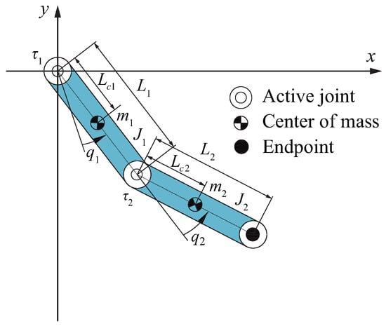
Figure 1.
Structure of the planar R-type fully actuated robot.
The dynamic model is
where , , and are the vector of the angle, angular velocity, and angular acceleration, respectively; is the inertia matrix with the characteristic of the symmetric positive definite; and contains the Coriolis and centrifugal forces. The detailed expressions of M and H are available in [20].
Let , then the state space equation can be written as
where
and
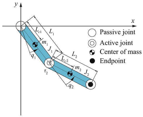
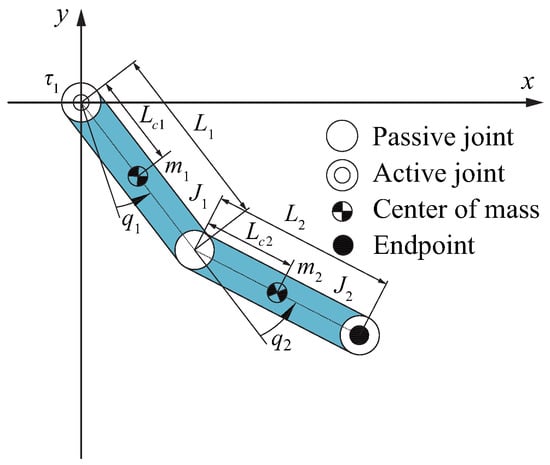
In the situation of the application, when one of the actuated joints of the system fails (which is marked ), the system will become an underactuated robot. Thus, on the basis of the failure joint location, the 2R underactuated robot is divided into 2 situations.
2.2. Underactuated Constraint Analysis
In order to design a general control method, the control characteristics must first be discussed. The underactuated part of (1) is
where indicates that the pth joint is the underactuated joint.
Based on (5), the motion states of the underactuated link can be calculated as follows:
except that p, and are the initial states of the underactuated link. Equation (6) gives the relationship between the underactuated link and actuated link.
3. Realization of the Objective of the Actuated Links
The first trajectory is planned based on the states of the actuated link. Next, the controller is designed to track to realize the objective of the actuated link.
3.1. The Trajectory of the First Part
The initial and final values of the trajectory should correspond to the initial and final angles of the actuated link. Only in this way can we achieve the control goal of driving the actuated link to move from the initial states to the target states. Thus, we designed the trajectory based on the initial angle and target angle for the actuated links.
The trajectory is designed as
where .
The derivatives of on time are
Equations (8) and (9) show that the actuated link can reach the target state by tracking the trajectory when .
3.2. Tracking Controller Design
The sliding mode surface is designed as follows:
and
where is the constant greater than zero.
The derivative of is
Let
where and are the positive coefficients.
The tracking controller is designed as follows:
The Lyapunov function is constructed as follows:
The derivative of (15) is the following:
When and , depend on LaSalle’s invariance theorem [57], we can acquire and . Thus, the actuated link tracks to reach its target states. However, the underactuated link rotates freely.
4. Realization of the Objective of the Underactuated Link
4.1. Trajectory Planning
According to (6), the second trajectory for the actuated link is constructed as
where
and
in which and are the fixed constant of the pulse function, , and A and w are the adjustable parameters of .
The derivatives of on time are
where
and
By tracking the trajectory, the actuated link can return from the target states to the target states within a period of time. Based on the derivation above, is dependent on A, w and . Therefore, the motion states of the actuated link can be changed by adjusting these three parameters, and the motion of the underactuated link can be adjusted indirectly.
4.2. Trajectory Parameter Solution Based on the Differential Evolution Algorithm
The evaluation function of the differential evolution algorithm is constructed as follows:
The calculation program of the trajectory parameters are shown as Algorithm 1.
In Algorithm 1, we use the“if” condition to determine the trajectory parameters and . When the “if” condition is satisfied, the trajectory parameters are output. When the condition is not true, the parameters are updated through the selection, crossover, and mutation operations to recalculate .
When the parameters are calculated by the differential evolution algorithm, the actuated link tracks back to its target states, and the underactuated manipulator will be controlled to its target states simultaneously.
| Algorithm 1: Trajectory parameters calculation. |
 |
4.3. Tracking Controller Design
The sliding mode surface is constructed as
and
where is the constant greater than zero.
The derivative of is
Let
where and are the positive coefficients.
The tracking controller is designed as follows:
The Lyapunov function is constructed as follows:
The derivative of (30) is the following:
When and depend on the LaSalle’s invariance theorem, we can acquire and . Thus, the actuated link tracks to reach its target states. According to the above analysis, the underactuated linkage can converge to the target state at the same time.
By using the Lyapunov method, we can prove the convergence and stability of the control system via controllers (14) and (29). Under the action of controller (14), the states of the actuated link converge to its target states at . Since the initial value of the second trajectory is also the target state, there will be no large disturbance and no influence on the system stability when the controller is switched to controller (29).
5. Simulations
In order to verify the effectiveness of the presented control method, simulations were run for the planar 2R underactuated robot using MATLAB/Simulink. Firstly, the parameters of planar underactuated robot were the same as those in [49]; see Table 1.

Table 1.
Parameters of the planar underactuated robot in [49].
Secondly, we chose the same parameters of planar underactuated robot as those in [20], which is shown in Table 2.
Table 2.
Parameters of the planar underactuated robot in [20].
The parameters of the differential evolution algorithm were set as , , . We chose s and . The parameters of the controllers (14) and (30) were , . and .
A simulation was carried out for the case of a zero initial velocity, a nonzero initial velocity, and a disturbance rejection, respectively, to verify the effectiveness of the proposed method.
5.1. Situation I: Zero Initial Velocity
Case A: planar underactuated robot
In order to verify the effectiveness of our control method, we chose the same structural parameters and motion states of the system as those in [49]. The motion states of the system were as follows:
The suitable parameters were obtained as follows:
In Figure 4, when s, the states of all links converge to their target values, the torque converges to zero, and the system is stabilized at the target states. The control time of [49] is more than 6 s. By comparison, our method can ensure that the system converges to the target position more quickly.
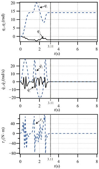
Figure 4.
Planar underactuated robot with the states (32).
Case B: planar underactuated robot
In order to verify our control method, we chose the same structural parameters and motion states of the system as those in [20]. The motion states of the system were as follows:
The parameters of trajectory were obtained as follows:
In Figure 5, when s, the angle of each link moves to the target angle, the angular velocity converges to zero, and the torque converges to zero. The system is stabilized at the target states. The control time of proposed method is shorter than that in [20]. The above results prove that our method can achieve the control goal faster.
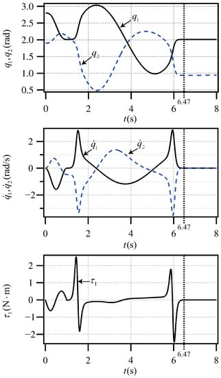
Figure 5.
Planar underactuated robot with the states (34).
5.2. Situation II: Nonzero Initial Velocity
Case A: planar underactuated robot
Considering the nonzero beginning velocity, we selected the same parameters as those in [49] and applied a nonzero beginning velocity on the underactuated link, given by the following:
The parameters of trajectory were obtained as follows:
On the basis of Case A in Situation I, the initial velocity of the passive joint was set to 0.02 rad/s. In Figure 6, when s, the states of all links converge to their target values, the torque converges to zero, and the system is stabilized at the target states. The system is stabilized at the given position. These results prove that this method can also ensure the system converges to the target position quickly, even if the passive joint has a nonzero initial velocity.
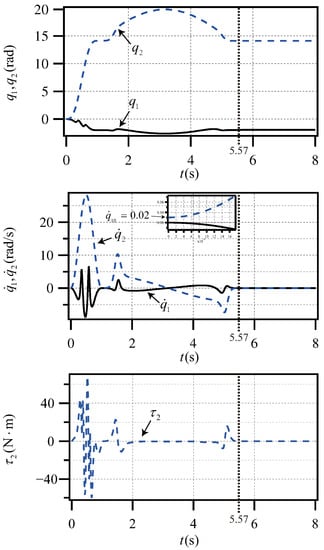
Figure 6.
Planar underactuated robot with the states (36).
Case B: planar underactuated robot
Considering the nonzero initial velocity, we selected the same parameters as those in [20] and applied a nonzero beginning velocity on the underactuated link, given by the following:
The parameters of trajectory were obtained as follows:
The initial velocity of the passive joint was rad/s in this situation. In Figure 7, when s, the angle of each link moves to the target angle, the angular velocity converges to zero, and the torque converges to zero. The planar underactuated robot is stabilized at the given states. These simulation results prove that the proposed method can solve the stable control problem of this system with a nonzero initial velocity.
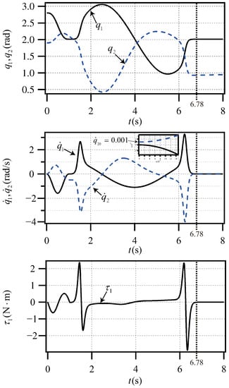
Figure 7.
Planar underactuated robot with the states (38).
5.3. Situation III: Disturbance Rejection
Case A: planar underactuated robot
In order to verify if our control method can overcome the disturbance of the actuated link, we chose the same parameters as those in [49], and a disturbance was obtained as follows
The parameters of trajectory were obtained as follows:
In Figure 8, when s, the states of all links converge to their target values, the torque converges to zero, and the system is stabilized at the target states. The system is stabilized at the given position. In the case of disturbance, our method still achieves the control goal, which proves the robustness of this method.
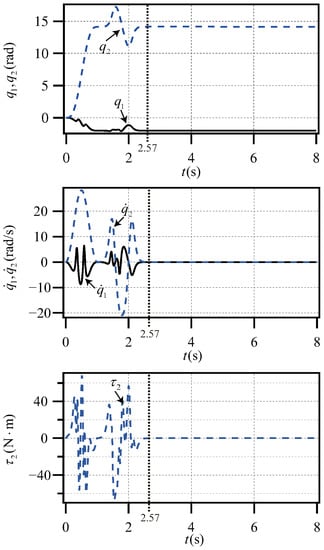
Figure 8.
Planar underactuated robot with the disturbance (40).
Case B: planar underactuated robot
In order to verify if our control method can overcome the disturbance of the actuated link, we chose the same parameters as those in [20] and applied a disturbance on the actuated link, given by the following:
The parameters of trajectory were obtained as follows:
We added a disturbance rejection in this simulation. In Figure 9, when s, the angle of each link moves to the target angle, the angular velocity converges to zero, and the torque converges to zero. The system is stabilized at the given states. The above analysis indicates that our method can overcome disturbance rejection and improve the anti-interference ability of the system.
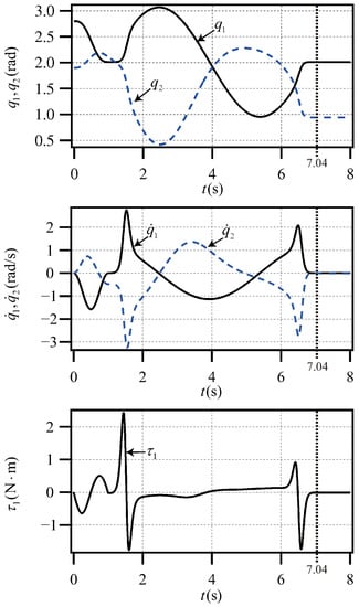
Figure 9.
Planar underactuated robot with the disturbance (42).
From the above simulation results, it is evident that our method is effective for the attitude control of the planar 2R underactuated robot with one underactuated joint in different positions. In our study, we considered cases of small nonzero initial velocity and disturbance rejection. The simulation results showed that the proposed method is still effective in these two cases.
6. Conclusions
We proposed a general control method via the differential evolution algorithm for the planar R-type underactuated robot. The total control program included two stages. In the first stage, we designed the trajectory from the states of the actuated link, and the controller was designed to track the planned trajectory to realize the objective of the actuated link. In the second stage, the trajectory with adjustable parameters was planned for the actuated link. Moreover, the adjustable parameters were calculated using the intelligent algorithm based on the underactuated constraints. Then, the controller was designed to track the planned trajectory to realize the objective of the actuated link and underactuated link. Finally, the proposed method was employed for the planar R-type underactuated robot, and the performance was verified through simulations.
This paper proposes a unified control strategy of the R-type underactuated manipulator with different structures, which was found to be suitable for conditions of nonzero initial velocity and disturbance rejection.
Author Contributions
Conceptualization, Z.H.; methodology, Z.H. and C.Y.; software, Z.H. and M.H.; validation, Z.H., M.H., Y.H., C.Y. and L.W.; formal analysis, Z.H. and C.Y.; investigation, Z.H., M.H., Y.H., C.Y. and L.W.; resources, Z.H.; writing—original draft preparation, Z.H., M.H. and Y.H.; project administration, Z.H.; funding acquisition, Z.H. All authors have read and agreed to the published version of the manuscript.
Funding
This research was funded by the Science and Technology Research Project of Hubei Provincial Education Department (no. D20211506), the Scientific Research Foundation of Wuhan Institute of Technology (no. K2021027), the Hubei Key Laboratory of Intelligent Robot (Wuhan Institute of Technology) (no. HBIRL202105), and the Graduate Innovative Fund of Wuhan Institute of Technology (no. CX2022123).
Institutional Review Board Statement
Not applicable.
Informed Consent Statement
Not applicable.
Data Availability Statement
Not applicable.
Conflicts of Interest
The authors declare no conflict of interest.
References
- Zhang, D.Q.; Li, X.A.; Yang, M.D.; Wang, F.; Xu, H. Non-random vibration analysis of rotate vector reducer. J. Sound Vib. 2023, 542, 117380. [Google Scholar] [CrossRef]
- Huang, P.; Huang, H.Z.; Li, Y.F.; Li, H. Positioning accuracy reliability analysis of industrial robots based on differential kinematics and saddlepoint approximation. Mech. Mach. Theory 2021, 162, 104367. [Google Scholar] [CrossRef]
- Niu, G.J.; Pan, B.; Fu, Y.L.; Qu, C.C. Development of a new medical robot system for minimally invasive surgery. IEEE Access 2020, 8, 144136–144155. [Google Scholar] [CrossRef]
- Sun, Y.; Wang, R. The research framework and evolution of service robots. J. Comput. Inf. Syst. 2019, 141, 227–234. [Google Scholar] [CrossRef]
- Herman, P. A quasi-velocity-based tracking controller for a class of underactuated marine vehicles. Appl. Sci. 2022, 12, 8903. [Google Scholar] [CrossRef]
- Yu, J.L.; Li, Z.; Lu, L.; Zhang, Y.S. Switching neural network control for underactuated spacecraft Formation reconfiguration in elliptic orbits. Appl. Sci. 2022, 12, 5792. [Google Scholar] [CrossRef]
- Li, G.Y.; Chen, B.J.; Chen, H.Y.; Deng, W. Fractional-order PIλDμ controller using adaptive neural fuzzy model for course control of underactuated ships. Appl. Sci. 2022, 12, 5604. [Google Scholar] [CrossRef]
- Yang, T.; Sun, N.; Chen, H.; Fang, Y.C. Neural network-based adaptive antiswing control of an underactuated ship-mounted crane with roll motions and input dead zones. IEEE Trans. Neural Netw. Learn. Syst. 2020, 31, 901–914. [Google Scholar] [CrossRef]
- Yang, T.; Sun, N.; Chen, H.; Fang, Y.C. Observer-based nonlinear control for tower cranes suffering from uncertain friction and actuator constraints with experimental verification. IEEE Trans. Ind. Electron. 2021, 68, 6192–6204. [Google Scholar] [CrossRef]
- Zhao, W.; Liu, H.; Lewis, F. Data-driven fault-tolerant control for attitude synchronization of nonlinear quadrotors. IEEE Trans. Autom. Control. 2021, 66, 5584–5591. [Google Scholar] [CrossRef]
- Jin, X.Z.; Che, W.W.; Wu, Z.G.; Deng, C.D. Robust adaptive general formation control of a class of networked quadrotor aircraft. IEEE Trans. Syst. Man Cybern. Syst. 2022, 52, 7714–7726. [Google Scholar] [CrossRef]
- Di, Z.; Sandipan, M.; Farhan, G. A differential-flatness-based approach for autonomous helicopter shipboard landing. IEEE/ASME Trans. Mechatronics 2022, 27, 1557–1569. [Google Scholar] [CrossRef]
- Raj, N.; Banavar, R.N.; Abhishek; Kothari, M. Robust attitude tracking for aerobatic helicopters: A geometric approach. IEEE Trans. Control. Syst. Technol. 2021, 29, 150–164. [Google Scholar] [CrossRef]
- Huang, Y.T.; Zhu, M.; Zheng, Z.W.; Low, K.H. Linear velocity-free visual servoing control for unmanned helicopter landing on a dhip with visibility constraint. IEEE Trans. Syst. Man Cybern. Syst. 2022, 52, 2979–2993. [Google Scholar] [CrossRef]
- Gu, N.; Wang, D.; Peng, Z. Observer-based finite-time control for distributed path maneuvering of underactuated unmanned surface vehicles with collision avoidance and connectivity preservation. IEEE Trans. Syst. Man Cybern. Syst. 2021, 51, 5105–5115. [Google Scholar] [CrossRef]
- Lai, J.; Lu, B.; Chu, H. Variable-stiffness control of a dual-segment soft robot using depth vision. IEEE/ASME Trans. Mechatronics 2022, 27, 1034–1045. [Google Scholar] [CrossRef]
- Huang, Z.X.; Li, X.P.; Wang, J.R.; Zhang, Y.; Mei, J.F. Human pulse detection by a soft tactile actuator. Sensors 2022, 27, 5047. [Google Scholar] [CrossRef]
- Huang, Z.X.; Lai, X.Z.; Zhang, P.; Meng, Q.X.; Wu, M. A general control strategy for planar 3-DoF underactuated manipulators with one passive joint. Inf. Sci. 2020, 534, 139–153. [Google Scholar] [CrossRef]
- Huang, Z.X.; Wei, S.Q.; Hou, M.Y.; Wang, L.J. Finite-time control strategy for swarm planar underactuated robots via motion planning and intelligent algorithm. Mearsurement Control 2023, 56, 813–819. [Google Scholar] [CrossRef]
- Huang, Z.X.; Lai, X.Z. Control strategy based on iterative method for planar Pendubot. In Proceedings of the 37th Chinese Control Conference, Wuhan, China, 25–27 July 2018; pp. 858–861. [Google Scholar]
- Zhang, P.; Lai, X.Z.; Wang, Y.W. A novel position-posture control method using intelligent optimization for planar underactuated mechanical systems. Mech. Mach. Theory 2019, 140, 258–273. [Google Scholar] [CrossRef]
- Huang, Z.X.; Lai, X.Z.; Wang, Y.W. Position control of planar three-link underactuated manipulator based on trajectory planning. Control. Decis. 2020, 35, 382–388. [Google Scholar]
- Huang, Z.X.; Wang, L.J. Review of control method of planar underactuated mechanical system. J. Wuhan Inst. Technol. 2021, 43, 448–454. [Google Scholar]
- Lai, X.Z.; Wang, L.J.; Cao, J.Q.; Wu, M. A simple and quick control strategy for a class of first-order nonholonomic manipulator. Nonlinear Dyn. 2016, 85, 2261–2276. [Google Scholar] [CrossRef]
- Zhang, P.; Lai, X.Z.; Wang, Y.W. Effective position-posture control strategy based on switching control for planar three-link underactuated mechanical system. Int. J. Syst. Sci. 2017, 48, 2202–2211. [Google Scholar] [CrossRef]
- Rsetam, K.; Cao, Z.; Wang, L.; Al-Rawi, M.; Man, Z. Practically robust fixed-time convergent sliding mode control for underactuated aerial flexible joint robots manipulators. Drones 2022, 6, 428. [Google Scholar] [CrossRef]
- Romano, D.; Wahi, A.; Miraglia, M. Development of a novel underactuated robotic fish with magnetic transmission system. Sensors 2022, 10, 755. [Google Scholar] [CrossRef]
- Huang, Z.X.; Lai, X.Z.; Zhang, P.; Wu, M. Trajectory planning and tracking control for positioning of planar three-link underactuated manipulator. In Proceedings of the Asian Control Conference, Kitakyushu, Japan, 9–12 June 2019; pp. 1243–1247. [Google Scholar]
- Huang, Z.X.; Zhou, Y.S.; Chen, Z.; Wang, W.; Wang, L.J. An universal control strategy for planar 2-DoF underactuated manipulator with one passive joint. In Proceedings of the Chinese Control Conference, Shanghai, China, 26–28 July 2021; pp. 468–472. [Google Scholar]
- Sheng, Y.; Lai, X.Z.; Wu, M. Position control of a planar three-link underactuated mechanical system based on model reduction. Acta Autom. Sin. 2014, 40, 1303–1310. [Google Scholar]
- Huang, Z.X.; Chen, Z.; Li, J.; Wang, L.J. Comprehensive unified control strategy for plananr 2-Link underactuated manipulators. In Proceedings of the Chinese Control and Decision Conference, Kunming, China, 22–24 May 2021; pp. 4514–4518. [Google Scholar]
- Huang, Z.X.; Qin, X.Y.; Wei, S.Q.; Wang, L.J. A finite-time posture control strategy for the swarm underactuated robots. In Proceedings of the Chinese Conference on Swarm Intelligence and Cooperative Control, Shenzhen, China, 28–30 October 2022; pp. 912–920. [Google Scholar]
- Huang, Z.X.; Qin, X.Y.; Chen, Z.; Wang, L.J. Position-posture control of underactuated manipulator based on intelligent optimization algorithm. Control. Eng. China 2022, 29, 1948–1953. [Google Scholar]
- Huang, Z.X.; Wan, X.; Zhou, Y.S.; Wang, L.J.; Wang, L.H. Stable control and disturbance rejection strategy for planar 2R underactuated robot via intelligent algorithm. In Proceedings of the Annual Conference of the Industrial Electronics Society, Brussels, Belgium, 17–20 October 2022. [Google Scholar] [CrossRef]
- Li, J.; Wang, L.J.; Chen, Z.; Huang, Z.X. Drift suppression control based on online intelligent optimization for planar underactuated manipulator with passive middle joint. IEEE Access 2021, 9, 38611–238619211. [Google Scholar] [CrossRef]
- Huang, Z.X.; Lai, X.Z.; Wang, Y.W.; Wu, M. Position control for planar 3R underactuated manipulator with second-order non-holonomic constraints. J. Southeast Univ. (Nat. Sci. Ed.) 2019, 49, 245–250. [Google Scholar]
- Wang, Y.W.; Lai, X.Z.; Zhang, Y.P.; Wu, M. Adaptive robust control for planar n-link underactuated manipulator based on radial basis function neural network and online iterative correction method. J. Frankl. Inst. 2018, 355, 8373–8391. [Google Scholar] [CrossRef]
- Wang, Y.W.; Lai, X.Z.; Zhang, P.; Wu, M. Control strategy based on model reduction and online intelligent calculation for planar n-Link underactuated manipulators. IEEE Trans. Syst. Man Cybern. Syst. 2020, 50, 1046–1054. [Google Scholar] [CrossRef]
- Xiong, P.Y.; Lai, X.Z.; Wu, M. A stable control for second-order nonholonomic planar underactuated mechanical system: Energy attenuation approach. Int. J. Control. 2018, 91, 1630–1639. [Google Scholar] [CrossRef]
- Liu, D.; Lai, X.Z.; Wang, Y.W.; Wang, X.B. Position control for planar four-link underactuated manipulator with a passive third joint. ISA Trans. 2019, 87, 46–54. [Google Scholar] [CrossRef]
- Wu, J.D.; Ye, J.W.; Wang, Y.W.; Su, C.Y. A general position control method for planar underactuated manipulators with second-order nonholonomic constraints. IEEE Trans. Cybern. 2021, 51, 4733–4742. [Google Scholar] [CrossRef]
- Huang, Z.X.; Qin, X.Y.; Wang, L.J.; Zhang, P. A general control strategy of planar multi-link underactuated manipulator with passive last joint based on nilpotent approximation and intelligent optimization. In Proceedings of the Chinese Automation Congress, Shanghai, China, 6–8 November 2020; pp. 4029–4031. [Google Scholar]
- Lai, X.Z.; Zhang, P.; Wang, Y.W.; Chen, L.F.; Wu, M. Continuous state feedback control based on intelligent optimization for first-order nonholonomic systems. IEEE Trans. Syst. Man Cybern. Syst. 2020, 50, 2534–2540. [Google Scholar] [CrossRef]
- Gao, X.; Ren, Z.; Zhai, L.; Jia, Q.X.; Liu, H.H. Two-Stage switching hybrid control method based on improved PSO for planar three-link under-actuated manipulator. IEEE Access 2019, 7, 76263–76273. [Google Scholar] [CrossRef]
- Huang, Z.X.; Qin, X.Y.; Wang, J.L. Position control of second-order Nonholonomic planar underactuated mechanical system. J. Wuhan Inst. Technol. 2021, 43, 567–572. [Google Scholar]
- Huang, Z.X.; Lai, X.Z.; Zhang, P. Virtual model reduction-based control strategy of planar three-link underactuated manipulator with middle passive joint. Int. J. Control. Autom. Syst. 2020, 19, 29–39. [Google Scholar] [CrossRef]
- Arai, H.; Tanie, K.; Shiroma, N. Nonholonomic control of a three-DOF planar underactuated manipulator. IEEE Trans. Robot. Autom. 1998, 14, 681–695. [Google Scholar] [CrossRef]
- Cao, J.Q.; Lai, X.Z.; Wu, M. Position control method fora planar Acrobot based on fuzzy control. In Proceedings of the China Control Conference, Hangzhou, China, 28–30 July 2015; pp. 922–926. [Google Scholar]
- Lai, X.Z.; She, J.H.; Cao, W.H.; Yang, S.X. Stabilization of underactuated planar acrobot based on motion-state constraints. Int. J. Non-Linear Mech. 2015, 77, 342–347. [Google Scholar] [CrossRef]
- He, G.P.; Wang, Z.L.; Zhang, J.; Geng, Z.Y. Characteristics analysis and stabilization of a planar 2R underactuated manipulator. Robotica 2016, 34, 584–600. [Google Scholar] [CrossRef]
- Wu, J.D.; Wang, Y.W.; Ye, W.J.; Sun, C.Y. Control strategy based on Fourier transformation and intelligent optimization for planar Pendubot. Inf. Sci. 2019, 491, 279–288. [Google Scholar] [CrossRef]
- Carsten, K.; Klaus, R. Control of underactuated manipulator using similarities to the double integrator. In Proceedings of the 18th IFAC World Congress, Milan, Italy, 28 August–2 September 2011; pp. 11501–11507. [Google Scholar]
- Lai, X.Z.; Zhang, P.; Wang, Y.W.; Wu, M. Position-posture control of a planar four-link underactuated manipulator based on genetic algorithm. IEEE Trans. Ind. Electron. 2017, 64, 4781–4791. [Google Scholar] [CrossRef]
- Lai, X.Z.; Wang, Y.W.; Wu, M.; Cao, W.H. Stable control strategy for planar three-link underactuated mechanical system. IEEE/ASME Trans. Mechatronics 2016, 21, 1345–1356. [Google Scholar] [CrossRef]
- Storn, R.; Price, K. Differential evolution-a simple and efficient heuristic for global optimization over continuous spaces. J. Glob. Optim. 1997, 11, 341–359. [Google Scholar] [CrossRef]
- Yang, M.; Li, C.H.; Cai, Z.H.; Guan, J. Differential evolution with auto-enhanced population diversity. IEEE Trans. Cybern. 2015, 45, 341–359. [Google Scholar] [CrossRef]
- LaSalle, J.P. Stability theory for ordinary differential equations. J. Differ. Equ. 1968, 4, 57–65. [Google Scholar] [CrossRef]


Disclaimer/Publisher’s Note: The statements, opinions and data contained in all publications are solely those of the individual author(s) and contributor(s) and not of MDPI and/or the editor(s). MDPI and/or the editor(s) disclaim responsibility for any injury to people or property resulting from any ideas, methods, instructions or products referred to in the content. |
© 2023 by the authors. Licensee MDPI, Basel, Switzerland. This article is an open access article distributed under the terms and conditions of the Creative Commons Attribution (CC BY) license (https://creativecommons.org/licenses/by/4.0/).