Article

Dynamic Path-Planning and Charging Optimization for Autonomous Electric Vehicles in Transportation Networks

1
College of Information Science and Technology, Donghua University, Shanghai 201620, China
2
Engineering Research Center of Digitized Textile and Apparel Technology, Ministry of Education, Donghua University, Shanghai 201620, China
3
Department of Engineering, Texas Southern University, Houston, TX 77004, USA
*
Authors to whom correspondence should be addressed.
Appl. Sci. 2023, 13(9), 5476; https://doi.org/10.3390/app13095476
Submission received: 3 April 2023 / Revised: 26 April 2023 / Accepted: 26 April 2023 / Published: 27 April 2023
(This article belongs to the Special Issue Transportation Planning, Management and Optimization)

Abstract

:
With the growing popularity of autonomous electric vehicles (AEVs), optimizing their path-planning and charging strategy has become a critical research area. However, the dynamic nature of transport networks presents a significant challenge when ensuring their efficient operation. The use of vehicle-to-everything (V2X) communication in vehicular ad hoc networks (VANETs) has been proposed to tackle this challenge. However, establishing efficient communication and optimizing dynamic paths with charging selection remain complex problems. In this paper, we propose a joint push–pull communication mode to obtain real-time traffic conditions and charging infrastructure information (i.e., charging stations and energy segments). We also analyze the selection of relay vehicles in multi-hop communication routing, considering factors such as link stability, vehicle distance, and reputation values. Furthermore, we formulate a dynamic optimization problem based on real-time information to minimize travel and charging costs. Our proposed algorithm enables AEVs to obtain charging services from charging stations and conduct dynamic wireless charging via energy segments. We present a dynamic real-time A* algorithm to solve the path-optimization problem and a dynamic real-time charging selection algorithm based on dynamic path optimization when the state of charge is lower than the charging threshold. Extensive simulations demonstrate that the proposed joint push-pull communication mode can provide vehicles the up-to-date information and the developed optimization algorithms effectively reduce travel and charging costs.

1. Introduction

Growing concern for the environment and advancements in autonomous technology have increased the popularity of autonomous electric vehicles (AEVs) [1,2,3]. AEVs are a type of intelligent vehicle, considered to be a higher-level electric vehicle [4]. They are powered by batteries, making them an eco-friendly alternative to conventional fuel vehicles and helping to reduce pollution and resource depletion [5]. Moreover, equipped with an intelligent computer system, AEVs can operate autonomously, making them a potential replacement for human drivers in the future [6]. This feature enables AEVs to achieve distributed decision-making, mitigating the complexity of data processing and time delays caused by centralized distribution, and avoiding the impact of driver self-interest behavior on global optimization. However, as the battery charge gradually decreases during movement [7], pure path optimization is insufficient to guarantee arrival at a specific destination.
State-of-the-art: To ensure sufficient power consumption during travel to a specific destination, AEVs should consider path optimization with charging solutions [8]. Researchers have studied the charging guidance of electric vehicles from the information flow interaction between electric vehicles and charging station operators. For instance, Liu et al. [9] proposed a route-optimization model to reduce user travel time and charging costs based on real-time charging prices and traffic conditions. Li et al. [10] established a charging path-planning model to minimize the travel time cost and charging cost of electric vehicle (EV) users based on real-time traffic information. Xing et al. [11] proposed a path-planning and charging navigation strategy for electric vehicles based on real-time traffic information. They developed a multi-objective optimization function that integrates road travel time, charging station load, and the number of incoming vehicles. They used an improved adaptive Dijkstra dynamic search algorithm to solve the problem and recommend the optimal driving and charging path. Considering the combination of transportation network and power network characteristics, Luo et al. [12] proposed a novel optimal charging scheduling strategy based on transport system information, such as road length, vehicle velocity, and waiting time, and grid system information, such as load deviation and node voltage, which improves both the transport system efficiency and the grid system operation. Most studies have focused on planning charging paths for electric vehicles using the interaction between EVs and the transportation network, with very few studies examining path and charging optimization for electric vehicles considering traffic conditions and the dynamic operation of charging stations.
Motivation: Dynamic optimization is crucial in adapting to time-varying traffic conditions and charging infrastructure status in complex transportation networks. To ensure the accuracy of dynamic optimization, real-time traffic and charging infrastructure service status information is essential [13]. Vehicle-to-everything (V2X) communication in vehicular ad hoc networks (VANETs) enables vehicles to exchange real-time information with other vehicles, roadside units (RSUs), and the power grid (charging infrastructure) via vehicle-to-vehicle (V2V), vehicle to roadside unit (V2R), and vehicle-to-grid (V2G) technologies. With the development of dynamic wireless power transmission technology, electronic coils can be installed on roads to create energy segments (ESs), which use electromagnetic induction to provide charging for electric vehicles. This means that AEVs can receive charging services not only from traditional charging stations (CSs) but also from ESs. Motivated by the realization of dynamic path optimization and charging selection, it is essential to establish a real-time communication mode to obtain real-time traffic conditions and charging infrastructure service status information. Additionally, suitable algorithms need to be developed to solve this dynamic optimization problem. Corresponding to these issues, the main contributions of this paper are as follows:
  • A joint push–pull communication mode is proposed to obtain real-time traffic conditions and charging infrastructure service status information. Moreover, the paper discusses the selection of relay vehicles based on link stability, vehicle distance, and service satisfaction in multi-hop communication routing.
  • A dynamic optimization problem is formulated based on the mode of real-time communication to solve the dynamic path optimization with charging selection. This problem considers several factors, such as travel time, queuing time, charging time, and consumption of charge, while also including both CSs and ESs as energy providers.
  • A novel approach for addressing dynamic optimization problems in transportation networks is proposed. The proposed method involves transforming the original problem into a series of single optimization problems and simplifying the road network through preprocessing. After that, a dynamic real-time A* (DRT-A*) algorithm is proposed to efficiently solve the path-optimization problem. Furthermore, a dynamic real-time charging selection (DRT-CS) algorithm based on dynamic path optimization to solve the charging selection problem is proposed.
Paper organization: The remainder of this paper is organized as follows. In Section 2, related work is reviewed. Section 3 describes proposed dynamic path optimization with a charging selection system. The transmission of real-time traffic conditions and charging infrastructures service status information is described in Section 4. Section 5 formulates AEV travel and charging costs. Section 6 describes dynamic path optimization with a charging selection model, and Section 7 proposes the simplified model and algorithm. Section 8 shows the performance evaluations. Section 9 concludes the paper.

2. Related Work

There is a significant body of literature on the path-planning and charging scheduling problem. Recent works have explored the use of VANETs to transmit traffic information and aid electric vehicles in making travel decisions. For example, Li et al. proposed vehicle-to-everything communication based on VANETs to enable transmission between electric vehicles and mobile edge computing servers for V2V charging navigation [14]. Wang et al. developed an intelligent power distribution system that used VANETs to enable communication among electric vehicles, RSUs, and a vehicle–traffic server, and proposed a globally optimal online electric-vehicle-charging strategy [15]. However, these centralized approaches can be computationally expensive, particularly in complex traffic networks. Bi et al. proposed communication based on clustering vehicular ad hoc networks for electric vehicles (EV-VANET), in which a cluster leader collected and maintained information for cluster members and transmitted information between adjacent clusters and RSUs [16]. However, this work did not consider real-time information transmission.
Recent research has focused on the path-planning and charging scheduling problem for electric vehicles, given their limited battery capacity. Liu et al. studied en-route charging navigation in both deterministic and stochastic traffic networks, formulating it as a dynamic programming problem [17]. They have also proposed simplified charge control and online state recursive algorithms to solve the deterministic and stochastic cases, respectively. Moreover, Liu et al. designed a joint routing and charging/discharging algorithm to minimize the total cost of electric vehicles, taking into account driving cost, electricity purchase cost, and battery degradation cost [18]. Another study by Liu et al. proposed an optimal charging station assignment and navigation plan to coordinate charging scheduling for electric vehicles. Using combined distributed biased min consensus algorithm and generalized benders decomposition algorithm to solve the complex nonlinear optimization problem [19]. However, conventional charging stations may be limited and inconvenient, particularly for AEVs with time anxiety. To address this issue, vehicular energy networks have emerged as a promising solution, using ESs with dynamic wireless power transmission capabilities to offer convenient energy charging services for AEVs while driving without the need to wait [20,21]. Manshadi et al. proposed a decentralized optimization framework for wireless charging stations to address the interdependence between electricity and transportation networks [22].
The optimization of travel path-planning and charging station selection for electric vehicles has become a highly researched topic in recent studies. Liu et al. proposed a planner for EVs by incorporating traveler behavior and energy consumption into the evaluation process by introducing a novel framework for the network design problem [23]. Wang et al. proposed a framework for V2V communication protocol to achieve context-aware path-planning, optimized for time and energy efficiency, as well as the best detour to the charging point in the case of insufficient energy [24]. However, their work assumed that each recharging point was always available, without considering the service status information of the recharging point. Yang et al. proposed a route selection and charging navigation optimization model to reduce the travel cost of electric-vehicle users and solved waiting-time calculations of charging stations based on queue theory [25]. Ding et al. proposed methods for charging warning and path-planning for electric vehicles with insufficient energy, analyzing energy consumption in real time and constructing network topology models of waiting time, queuing mechanism, and charging calculation [26]. Schoenberg et al. proposed an adaptive charging and routing strategy that considers driving, waiting, and charging time, minimizing waiting times at charging stations for long-distance trips with electric vehicles by announcing planned charge stops to a central charging station database. They developed a multi-criterion shortest-path search algorithm using contraction hierarchies [27]. Del Razo et al. proposed a smart scheduling approach for planning charging stations on expressways based on the A* algorithm with constraint verification and a peer-to-peer scheduling system. By considering the estimated state of charging stations, indirect coordination between electric vehicles is realized, aiming to minimize the total travel time of each electric vehicle [28]. Ferro et al. proposed an optimization model that minimizes the total travel distance and energy purchase cost depending on the chosen charging method. Their work considered the choice of different types of charging modes at the charging station, the speed of the electric vehicles, the loaded cargo, and the battery charge. Furthermore, they proposed a preprocessing algorithm to reduce the problem dimension [29]. Gusrialdi et al. presented a distributed algorithm to schedule electric-vehicle flows into neighboring charging stations so that electric vehicles are all appropriately served along the highway and that all the charging resources are uniformly used [30]. Weist used a dynamic programming algorithm that takes into account vehicle, road, and charging station parameters to optimize the routing and charging combination for electric vehicles [31]. Embleton et al. developed an optimal charging/discharging decision-making and optimal hourly electricity prices problem. It focused on finding proper electric-vehicle-charging stations by electric-vehicle owners and determining optimal hourly electricity prices traded between all agents such that the rewards of electric-vehicle-charging stations and electric-vehicle owners are met simultaneously [32]. Alqahtani et al. developed a reinforcement learning model to tackle the uncertainties in power supply and demand by dispatching a fleet of electric vehicles to supply energy to different consumers at different locations. Each electric vehicle is equipped with various energy resources such as photovoltaic panels and energy-storage units. By sharing power generation and storage units among multiple consumers, the model aims to reduce energy costs for each consumer [33]. Subramanian et al. considered interactions between the transportation and electric power networks and formulated a multi-objective optimization model to develop optimal routing strategies. The multi-objective component considers the trade-off between travel time and charging cost. The upper level obtains the routing decision by minimizing the function of charging cost and travel time. The routing decision is used in the lower level that solves the AC optimal power flow model, using second-order cone constraints, to determine nodal electricity prices [34]. Table 1 shows the different characteristics in previous works. “×” represents the characteristic considered by the previous works.
As shown in Table 1, research in electric-vehicle path-planning and charging scheduling has been ongoing to reduce charging costs. However, there is still a lack of VANET-based real-time traffic and charging infrastructure service information acquisition, as well as distributed dynamic optimization to adapt to changes in the transportation network. Furthermore, most studies only consider the problem of charging scheduling at fixed charging stations, while only a few studies have examined the dynamic wireless charging problem using energy segments. Thus, this paper aims to address the dynamic path optimization and charging selection problem by incorporating real-time traffic information and the service status of charging infrastructure.

3. System Model

In this section, we describe the dynamic path and charging system in detail. The notation table and nomenclature table in this paper are shown in Table 2 and Table 3.

3.1. Transportation Network Architecture

As shown in Figure 1, the transportation network architecture includes a road network and communication network, which is composed of AEVs, charging infrastructures, and RSUs. The V2X topology is considered to be a combination of V2V, V2I, and V2G. In the V2X topology scenario, AEVs can communicate with each other and with RSUs via one-hop or multi-hop. AEVs can also communicate with charging infrastructures via one-hop and multi-hop V2V and V2R. RSUs can communicate with each other through wired connections. The V2X topology can help create a connected and efficient transportation system that allows for real-time information exchange, which can improve the efficiency and convenience of the overall transportation system. The details are as follows:
The road network is described as G ( V , Θ ) , where V stands for the set of road nodes, and | V | = N , Θ represents the set of road segments, and | Θ | = M . For i , j V , if there is a direct road segment formed, we express it as ( i , j ) , and ( i , j ) Θ . If the road segment ( i , j ) is an ES, then r i j = 1 , otherwise r i j = 0 . Θ e represents the set of all ESs. We set O ( i ) = { j V | ( i , j ) Θ } as the adjacent node of road node i. The length of section ( i , j ) is expressed as L i j . Since all road segments in the road network have driving directions, to distinguish different lane directions, we define ( i , j ) and ( j , i ) as two different segments, i.e., ( i , j ) is not equal to ( j , i ) , but L i j = L j i . The starting node and destination node of AEV are denoted as s and d, respectively. The time of AEV at the starting node is denoted as t s .
AEVs are equipped with a global positioning system (GPS), sensing system, and computer system, which can detect its own travel information and can constantly update it. The travel information of an AEV includes the state of charge (SoC), speed, road segment ID, and time stamp. Each AEV is equipped with an on-board unit (OBU) to realize the communication between V2V, V2R, and V2G [35,36]. An AEV obtains real-time traffic conditions and charging infrastructures service status information from the nearest RSU via the proposed joint push-pull communication mode to realize dynamic path optimization and charging selection. We assume that the time for AEV k to enter the intersection communication range at road node i is similar to the time for AEVs to arrive at road node i, expressed as t i k , and the time of AEV k leaving road node i is denoted as t i k . τ i j k , r ( t s ) represents the travel time of the AEV k on the road segment ( i , j ) estimated by the starting node based on the traffic information at this time, and assume that the SoC of AEV k reaching the road node i and reaching the c s i is the same, denoted as C i k . E i j k ( t ) is the consumption of charge of AEV k on the road section ( i , j ) .
Charging infrastructures includes CSs and ESs. CSs communicate service status information (e.g., the number of charging slots in service and the remaining time, the number of vehicles in the queue, number of vehicles leaving the queue) to the nearest RSU. In this paper, we discuss the uneven distribution of CSs in some intersections. We assume that CSs are only deployed at road nodes. For example, if a CS is deployed at road node i, it is denoted as c s i , and V c s is used to denote the set of CSs. ESs are formed by charging/discharging tracks, which are composed of coils buried under the road and connected to the energy-storage device by a common bus. When AEVs move on the charging/discharging track, the energy can be transmitted to the AEVs wirelessly and dynamically. Energy deficiency can be compensated for by an energy-storage device, while excess energy can be stored. ESs communicate the service status information (e.g., the number of charging AEVs, the reserved number of AEVs, and arrival time) to the nearest RSU.
RSUs cache the static and dynamic information of road segments and charging infrastructures within the communication range. The static information includes the length of the road segment, the ID of the road segment, and the location of charging infrastructures. The dynamic information includes the traffic conditions and the charging infrastructure service status information. RSUs can obtain information about cached road segments and charging infrastructures on other RSUs through wired communication.

3.2. Dynamic Path and Charging System Process

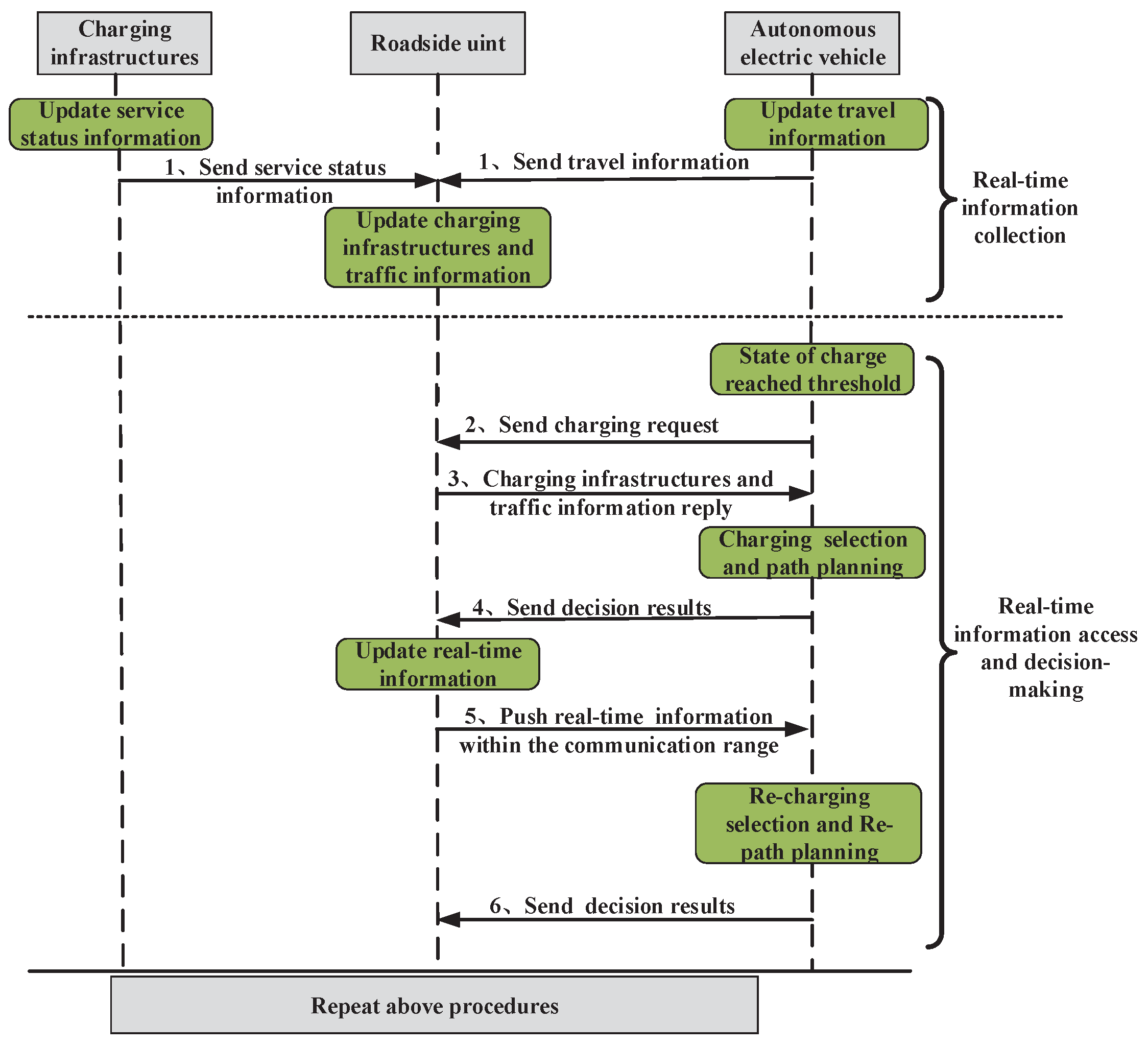
The procedures of dynamic path-4planning and charging selection system includes a real-time information-collection phase and a real-time information-access and decision-making phase, as shown in Figure 2.
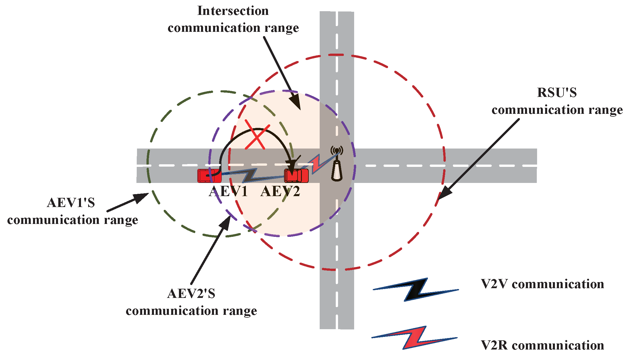
In the real-time information-collection stage, RSUs play a critical role in caching the information flow between charging infrastructures and AEVs. Procedure 1 in the Figure 2 updates the charging infrastructure service status and AEV travel information to nearby RSUs. However, due to the limited coverage of RSUs at intersections, AEVs within the intersection communication range can exchange information with the RSU through one-hop V2R communication. By contrast, AEVs outside the intersection communication range need to transmit information through multi-hop V2V and V2R communication. We assume that each charging infrastructure is deployed within the communication range of an RSU, and the service status information of charging infrastructures can be directly transmitted to RSUs through its built-in intelligent device. The intersection communication range is defined as the overlapping area of the AEV and RSU communication range, as shown in Figure 3. AEV1 and RSU are not within range for intersection communication, which means they cannot communicate directly. By contrast, AEV2 and RSU are within the range of intersection communication, allowing them to communicate through V2R.
In the real-time information-access and decision-making phase, when the SoC level of the AEV is lower than the charging threshold, the AEV sends charging requests to the nearby RSU through one-hop V2R or multi-hop V2V, and the RSU receiving the charging request replies with real-time information to the AEV, as shown in procedures 2 and 3 in the Figure 2. The AEV then uses the information to complete path and charging optimization and send decision results to the RSU, as shown in procedure 4 in the Figure 2. When the RSU receives the traffic accident information, it can transmit that information to the corresponding AEV via one-hop V2R or multi-hop V2V communication, as shown in procedure 5 in the Figure 2. The AEV can use the updated information to replan the path and charging selection, and send updated decision results to RSU, as shown in procedure 6 in the Figure 2.

4. Joint Push–Pull Communication Mode

In this section, we detail the process of information transfer in the joint push–pull communication mode and the selection of relay vehicles in a multi-hop communication routing.
Real-time traffic conditions and charging infrastructure service status information are crucial for dynamic path optimization and charging selection of AEVs. We improve the traditional push–pull mode and propose a joint push–pull communication mode for AEVs to access real-time traffic conditions and charging infrastructures service status information from RSUs. Push communication mode is a passively accepted communication mode. The vehicle passively receives information from nearby RSUs. Pull communication mode is a request-based mode in which vehicles request specific information only when they need it [37].
The joint push–pull communication mode combines the strengths of these two modes to improve communication efficiency. It allows vehicles to request specific information as needed while actively sending their own information when appropriate, and passively receiving information from nearby RSUs. Therefore, the joint push–pull communication mode can provide a more efficient communication framework and contribute to the overall performance of the VANET system. On the one hand, the RSU sends information to AEV in push mode. The analysis is as follows:
Case1: The RSU periodically publishes charging infrastructure service status information to vehicles within the intersection communication range.
Case2: When normal traffic is affected by a traffic accident, the RSU sends the accident message (road segment ID, estimated impact time) to the vehicles on the nearest road segment.
On the other hand, the AEV requests information from the RSU in pull mode. When the SoC of the AEV is lower than threshold Ω and cannot support it to reach the destination, the AEV implements V2G through one-hop V2R or multi-hop V2V and V2R to obtain charging infrastructures service status information, facilitating the identification of available charging infrastructure.
For multi-hop communication routing, we mainly consider the stability, distance, and reputation values of adjacent vehicle nodes, and define a metric N R to select the best next-hop vehicle node with the smallest N R . The expression of N R is as follows:
N R = ξ 1 L S k h + ξ 2 D k h + ξ 3 M k h ,
here, 0 ξ 1 1 , 0 ξ 2 1 , 0 ξ 3 1 , and ξ 1 + ξ 2 + ξ 3 = 1 , L S k h , D k h and M k h are the link stability, distance between vehicle node h and last-hop vehicle node k, and the reputation values of vehicle node k, respectively.
Link stability is an indicator to measure the lifetime of the wireless link between two vehicular nodes, which was proposed in [38]. Assuming that the positions of vehicle k and its neighbor node h at time t are ( x k , y k ) and ( x h , y h ) , and the positions of them at time t + Δ t are x k , y k and x h , y h . The movement vectors of node k and h in time interval Δ t are m k x , m k y = x k x k , y k y k and m h x , m h y = x h x h , y h y h , respectively. Then, link stability is defined as:
L S k h = 1 min m k x m h x 2 + m k y m h y 2 , R R ,
where R is the communication range of vehicles. h N k , N k is the set of neighbor nodes of the vehicle k. Larger L S k h denotes a lower variation in the position between two vehicles k and h.
To reduce the delay, the last-hop vehicle selects the vehicle node that is as far as possible within its communication range as the next-hop forwarding node.
D k h = x k x h 2 + y k y h 2 R .
Reputation values evaluate the ability of vehicle nodes to forward data packets, which is assessed by the difference between the actual packet loss monitored and the estimated normal loss. Every vehicle node monitors neighboring vehicle nodes to evaluate reputation values. The total packets lost in the transmission from vehicle node k to vehicle node h can be calculated as [39]:
M k h = S k h F k h ,
where M k h is the total number of packets lost because of normal and malicious activity, S k h is the total number of data packets sent from vehicle node k to vehicle node h, and F k h is the total number of data packets forwarded by vehicle node k. The relay-forwarding vehicle selection in a multi-hop communication routing is shown in Algorithm 1.
Algorithm 1: Relay Vehicle Selection Algorithm.
1:
s v -source (RSU/vehicle), t a -destination (vehicle/RSU)
2:
L S k h - link stability between vehicle k and h
3:
D k h - distance between vehicle k and h
4:
M k h - reputation values of vehicle k
5:
N k - the set of neighbors of forwarding vehicle
6:
while s v t a do
7:
   for each vehicle h N k  do
8:
     Calculate L S k h E q u a t i o n   ( 2 ) , D k h E q u a t i o n   ( 3 ) and M k h E q u a t i o n   ( 4 ) .
9:
     Calculate N R E q u a t i o n   ( 1 )
10:
     if  N R is minimum then
11:
        Select vehicle h as relay vehicle.
12:
     end if
13:
   end for
14:
end while

5. Mathematical Formulations for Vehicle Travel and Charging

In this section, we describe the travel and charging costs.

5.1. Time Cost

The time consumption of AEV includes three parts: travel time, queuing time, and charging time. The details are as follows.

5.1.1. Travel Time

The travel time of AEVs is affected by the traffic flow density (TFD) on the road segment. According to the traffic information on the road network at time t, the travel time on each road segment can be estimated [40].
Case1: The travel time of AEV k on segment ( i , j ) Θ e can be expressed as
τ i j k , r ( t ) = 1 + α η i j ( t ) β L i j V i j ,
where V i j is the free-flow speed of the vehicle on segment ( i , j ) . η i j ( t ) is the TFD on segment ( i , j ) . α and β are adjustment parameters that quantitatively define the relationship between speed and TFD. TFD can be expressed as [41],
η i j ( t ) = Q i j ( t ) Q i j m a x , ( i , j ) Θ ,
where Q i j m a x is the maximum AEVs capacity on segment ( i , j ) , and Q i j ( t ) is the number of AEVs on road segment ( i , j ) at time t.
Case2: The travel time of AEV k on segment ( i , j ) Θ e can be expressed as
τ i j k , r ( t ) = L i j V i j ,
where V i j is the travel speed while charging on the segment ( i , j ) Θ e .

5.1.2. Queuing Time

The arrival of AEVs at the charging infrastructure can be modeled as a time-dependent stochastic process, which can be represented as a Poisson process. The parameter λ ( t ) of the Poisson process describes the average arrival rate of AEVs at a charging infrastructure during time slot t. The probability that n AEVs arrive at the charging infrastructure during time slot t is given as [42],
P { n } = e λ ( t ) ( λ ( t ) ) n n ! , n = 0 , 1 , 2 .
At the CS, the number of charging slots in service and the remaining time of charger service can be obtained by CS smart devices. f c s i u ( t ) represents the remaining service time of the u th charging slot. The queue number of vehicles on c s i at time t can be given by
Z c s i ( t ) = m a x { 0 , Z c s i ( t 1 ) + λ ( t ) p c s i ( t ) } ,
where Z c s i ( t ) represents the number of AEVs queuing at c s i at time t. p c s i ( t ) denotes the number of vehicles that have been fully recharged and leave the CS during time slot t.
The queuing time at the t can be obtained by
τ c s i w ( t ) = 0 , Z c s i ( t 1 ) + λ ( t ) p c s i ( t ) < 0 , f c s i Z c s i ( t ) + 1 ( t ) , Z c s i ( t 1 ) + λ ( t ) p c s i ( t ) 0 .

5.1.3. Charging Time

The demand charge of AEV k is denoted as C a k , and assumes the charging speed of the AEV is a constant. The charging time of AEV in the ESs is the travel time. If the AEV obtains the required charge in advance, it will automatically turn off the inductive charging with the ES.
τ i j k , c ( t ) = L V i j ,
where L is the length of mobile charging on ES. The charging time of AEV k at CS can be expressed as
τ c s i k , c ( t ) = C a k C i k v c s i ,
where v c s i represents the charging rate on c s i ; they are small, medium, and large.
Φ 1 represents the CS set selected by AEV. When the AEV starts, Φ 1 = , and when the AEV selects c s i for charging, c s i is added to the set Φ 1 . Therefore, during the AEV k travel, the time t i k when AEV leaves the road node i can be expressed as
t i k = t i k , c s i Φ 1 , t i k + τ c s i k , w + τ c s i k , c , c s i Φ 1 .
The time t j k to reach road node j O ( i ) can be expressed as
t j k = t i k + τ i j k , r .
The SoC of AEV leaving road node i can be expressed as
C i k ( t i k ) = C i k , c s i Φ 1 , C a k , c s i Φ 1 .
where C i k ( t i k ) represents the SoC when AEV k leaves road node i.

5.2. Charge Consumption

As soon as the AEV moves, it gradually discharges the battery. Therefore, the consumption of charge [43] of AEV k on road segment ( i , j ) can be expressed as
E i j k ( t ) = 0 τ i j k , r ρ 2 φ A k V i j 1 + α η i j ( t ) β + v f 2 + M k g f r cos θ i j + sin θ i j V i j 1 + α η i j ( t ) β d t ,
where τ i j k , r represents the estimated travel time of AEV k on segment ( i , j ) . f r k is the rolling friction coefficient of AEV k, M k is the total mass and load of AEV k, g is the gravitational acceleration, ρ is the air density, φ is the air resistance coefficient, A k is the frontal area of AEV k, and v f is the wind speed. θ i j is the slope of segment ( i , j ) .
The SoC of AEV traveling from node i to node j can be expressed as
C j k = C i k ( t i k ) E i j k , j O ( i ) ,
where C j k represents the SoC when the AEV k reaches road node j.

6. Dynamic Path Optimization with Charging Selection

In this section, we consider dynamic path optimization with charging selection based on real-time network information, taking into account the minimum travel cost and charging cost.

6.1. Problem Formulation

We aim to minimize the total cost of AEV from the starting node to the destination. The total cost consists of two parts: travel cost and charging cost. The travel cost of AEV k can be expressed as
f 1 k = i = s j O ( i ) j = d p t τ i j k , r ( t ) + p e E i j k ( t ) x i j k ( t ) ,
where p t and p e are the monetary value of time and energy for AEV, τ i j r , k ( t ) and E i j k ( t ) are estimated travel time and consumption of charge cost on the road segment ( i , j ) according to the real-time traffic information, respectively. x i j k ( t ) is a variable to indicate if AEV k selects segment ( i , j ) .
AEV selects segment ( i , j ) , x i j k ( t ) = 1 ; otherwise x i j k ( t ) = 0 , and the starting node and destination must have a selected road segment to leave and arrive.
i , j V j O ( i ) x i j k ( t ) = 1 , i = s or j = d or AEV k select segment ( i , j ) , 0 , AEV k does not select segment ( i , j ) .
The current SoC is greater than the total consumption of charge of the selected road segment.
i = s j O ( i ) j = d E i j k x i j k ( t ) C s k .
Traffic congestion has always been the biggest headache for drivers, which increases the travel cost of vehicles [44]. For an AEV, traffic congestion directly increases its consumption of charge and travel time. Therefore, the balanced use of road resources and the reduction of road congestion can improve travel efficiency and reduce travel costs.
η i j ( t i k ) δ ,
where δ is a parameter to control the size of TFD, which can be adjusted according to the historical traffic conditions of different segments in different time periods.
When the AEV SoC cannot support it to reach the travel destination and is below the charging threshold Ω , AEV k needs to select charging infrastructure to complete the charging. The charging cost can be expressed as
f 2 k = c s i V c s ( i , j ) Θ e p t τ c s i k , w ( t ) + τ c s i k , c ( t ) + p c s C a k y c s i k , c s ( t ) + p r τ i j k , c λ y i j k , e s ( t ) ,
where τ c s i k , w ( t ) , τ c s i k , c ( t ) is the estimated queuing time cost and charging time cost. λ is the charging efficiency per unit of time on ES. p c s and p r are the unit electricity prices of the CS and ES, respectively; and p c s < p r . y c s i k , c s ( t ) and y i j k , e s ( t ) are variable that describes which charging infrastructure the AEV chooses,
y c s i k , c s ( t ) = 0 , AEV k does not select c s i , 1 , AEV k select c s i .
y i j k , e s ( t ) = 0 , AEV k does not select ( i , j ) , r i j = 1 , 1 , AEV k select ( i , j ) , r i j = 1 .
AEV k can only select one charging infrastructure at a time.
c s i V c s ( i , j ) Θ e y c s i k , c s ( t ) + y i j k , e s ( t ) = 0 , AEV k is not charging , 1 , AEV k select c s i or ( i , j ) .
where r i j = 1 . To ensure that AEV k can successfully reach the selected CS,
E ¯ s , c s i k y c s i k , c s ( t ) C s k , c s i V c s ,
where C s k represents the SoC of starting node, and E ¯ s , c s i k is the average value of the estimated consumption of charge under the path from starting node to c s i . To ensure that AEV k can successfully reach the selected ES
E ¯ s , i k r i j y i j k , e s ( t ) C s k , ( i , j ) Θ e ,
where E ¯ s , i k is the average value of the estimated consumption of charge under the path from starting node to node i with ES ( i , j ) .
To prevent charging queues from growing uncontrollably and to reduce queuing time for vehicles, AEVs must take into account acceptable queuing time constraints when making decisions.
τ c s i k , w ( t ) y c s i k , c s ( t ) P ,
where P is the AEV tolerance index, indicating the maximum queuing time at c s i acceptable to AEV k.

6.2. Optimization Model

In this paper, AEVs can calculate their travel costs and charging costs based on real-time traffic conditions and the service status information of the charging infrastructure in the network. The travel cost and charging cost of each AEV are expressed as a weighted sum with specific weights. Therefore, the optimization model can be formulated as follows:
min x i j k ( t s ) y c s j k , c s ( t ) y i j k , e s ( t ) w r i = s j O ( i ) j = d p t τ i j k , r ( t ) + p e E i j k ( t ) x i j k ( t ) + w c c s i V c s ( i , j ) Θ e p t τ c s i k , w ( t ) + τ c s i k , c ( t ) + p c s C a k y c s i k , c s ( t ) + p r τ i j k , c λ y i j k , e s ( t ) , s . t . ( 19 ) , ( 20 ) , ( 21 ) , ( 23 ) , ( 24 ) , ( 25 ) , ( 26 ) , ( 27 ) , ( 28 )
where the subscript i starts from the starting node s, and j ends at the destination (travel or charging infrastructure) node d. w r and w c are parameters that adjust the weight of travel time and consumption of charge cost, which are defined as:
w r + w c = 1 .
According to (30), when 0.5 w r 1 , 0 w c 0.5 , which means that AEV prefers travel cost efficiency. When 0 w r 0.5 , 0.5 w c 1 indicates that AEV prefers charging cost efficiency.

7. Simplified Model and Algorithm

In this section, we transform the original problem into a travel problem and a charging problem to solve the optimization problem considering that there are decision variables y c s i k , c s ( t ) , y i j k , e s ( t ) and x i j k ( t ) in problem (29), which is difficult to solve directly.

7.1. Travel Problem Model

We convert the original problem (29) to a travel problem and charging problem. If the complicated decision variable x i j k ( t ) is fixed in advance, the rest of the problem will be easier to solve. First, to determine the decision variable x i j k ( t ) , we can convert the original problem (29) into problem
min x i j k ( t s ) w r i = s j O ( i ) j = d p t τ i j k , r ( t ) + p e E i j k ( t ) x i j k ( t ) , s . t . ( 19 ) , ( 20 ) , ( 21 ) .
For problem (31), the increasingly large road network makes the search increasingly difficult for vehicles to planning paths. Therefore, to decrease the computational complexity of the problem, we introduce two preprocessing techniques to reduce the number of road segments in G:
  • SoC-based road segment elimination
  • TFD-based road segment elimination
The AEV travels on electrical energy, and the preprocessing eliminates a segment ( i , j ) Θ if the AEV cannot reach node j from node i considering the consumption of charge due to cover the segment.
C i k E i j k 0 , j O ( i ) ,
We eliminate the segments that do not meet constraint (32) and obtain a reduced graph G.
To reduce the traffic congestion caused by the simultaneous influx of a large number of AEVs into a road segment, the preprocessing eliminates a segment ( i , j ) Θ , if the AEV cannot reach node j from node i considering the road segment’s TFD constraint (21).
However, the value of threshold δ in the TFD constraint (21) has an impact on the vehicle path-planning result and consequently on the travel time. Therefore, a big question about this path optimization is how to set the TFD threshold. The answer to this question is shown in Section 8.2.
For the path-optimization problem (31), we propose a DRT-A* algorithm. Compared with A* algorithm [45], we conduct a path search based on real-time traffic condition information and consumption of charge, and adjust the start–destination pair considering traffic conditions and the SoC level of AEV to achieve dynamic real-time path-planning, as shown in Algorithm 2.
Algorithm 2: DRT-A* algorithm.
1:
Input: Map, Start–Destination (travel or charging infrastructure) pair, SoC
2:
Output: The optimal path from the start node to destination.
3:
Initialize t=simulation.start
4:
Calculate Equation (21), Equation (32)
5:
while traci.simulation.getMinExpectedNumber()>0 do
6:
   Set current node=start node
7:
   Put start node into openset.
8:
   while openset is not empty do
9:
     for neighbors in map[current node] do
10:
        if next node in openset then
11:
          t_travel(t)[current node,next node] E q u a t i o n ( 5 )
12:
          E(t)[current node,next node] E q u a t i o n ( 16 )
13:
          e(t)[next node] E q u a t i o n ( 33 )
14:
          g(t)[next node] E q u a t i o n ( 34 )
15:
          f(t)[next node] E q u a t i o n ( 34 ) + E q u a t i o n ( 35 )
16:
          if e(t)[next node]≤ C(t)[next node] & & the node with lowest f(t)[next node] then
17:
             Update g(t)[next node]
18:
             Update t and SoC
19:
          end if
20:
        else
21:
          Put next node into openset
22:
        end if
23:
     end for
24:
   end while
25:
   if current node == Destination then
26:
     Return path
27:
   end if
28:
   if destination charges then
29:
     Update start–destination pair
30:
     Go to line 6
31:
   end if
32:
end while
Compared with the fixed travel cost in the A* algorithm, we discuss the consumption of charge cost e i ( t ) and redefine the real-time travel cost g i ( t ) and estimated travel cost h j ( t ) in the DRT-A* algorithm.
e i ( t ) is the consumption of charge cost from the starting node s to the current node i, initialization e s ( t ) = 0 , and the consumption of charge cost of the neighbor node j of the current node i is expressed as,
e j ( t ) = e i ( t ) + E i j ( t ) .
g i ( t ) is the travel cost from the starting node s to the current node i, initialization g s ( t ) = 0 , and the travel cost of the neighbor node j of the current node i is expressed as
g j ( t ) = g i ( t ) + p t τ i j r ( t ) + p e E i j ( t ) .
h i ( t ) is the estimated travel cost from the node i to the destination node d,
h i ( t ) = p t τ i , d r ( t ) + p e E i , d ( t ) .
In terms of complexity, compared with the A* algorithm, the DRT-A* algorithm simplifies the road network G based on TFD and SoC, therefore shortening the calculation time.

7.2. Charging Problem Model

Then, if the SoC value of AEV k is less than the charging threshold Ω , for a set of fixed values of x i j k ( t ) , we can convert the original problem (29) into problem,
min y c s j k , c s ( t ) y i j k , e s ( t ) w r c s j V c s ( i , j ) Θ e p t τ c s i k , w ( t ) + τ c s i k , c ( t ) + p c s C a k y c s i k , c s ( t ) + p r τ i j k , c λ y i j k , e s ( t ) , s . t . ( 23 ) , ( 24 ) , ( 25 ) , ( 26 ) , ( 27 ) , ( 28 ) .
For the charging selection problem (36), based on the decision variable x i j k ( t ) determined by the DRT-A* algorithm, we propose a DRT-CS algorithm. We make charging selections according to the real-time charging infrastructures service status information and consider the travel and charging costs to adjust the selection, as shown in Algorithm 3.
Algorithm 3: DRT-CS algorithm.
1:
Input: Charging infrastructures, SoC, t
2:
Output: The optimal charging infrastructure
3:
Load charging infrastructures service status information
4:
Load path, and travel cost via Algorithm 2
5:
for charging infrastructure meet Equations (26)–(28) do
6:
   Calculates Equation (22)
7:
   if the sum is minimum then
8:
     Return the optimal charging infrastructure
9:
   end if
10:
end for
11:
if Optimal charging infrastructure changes then
12:
   Update t
13:
   Go to line 4
14:
end if

8. Performance Analysis

In this section, we introduce the performance evaluations of dynamic path optimization with charging selection based on real-time transportation network information. To verify the effectiveness of our proposed method, numerical experiments are conducted to compare it with relevant and representative methods [28,29], as these studies consider most of the relevant characteristics in path-planning and charging problems. The characteristics of their studies are complementary and representative of the research in this field, as shown in Table 1.

8.1. Simulation Setup

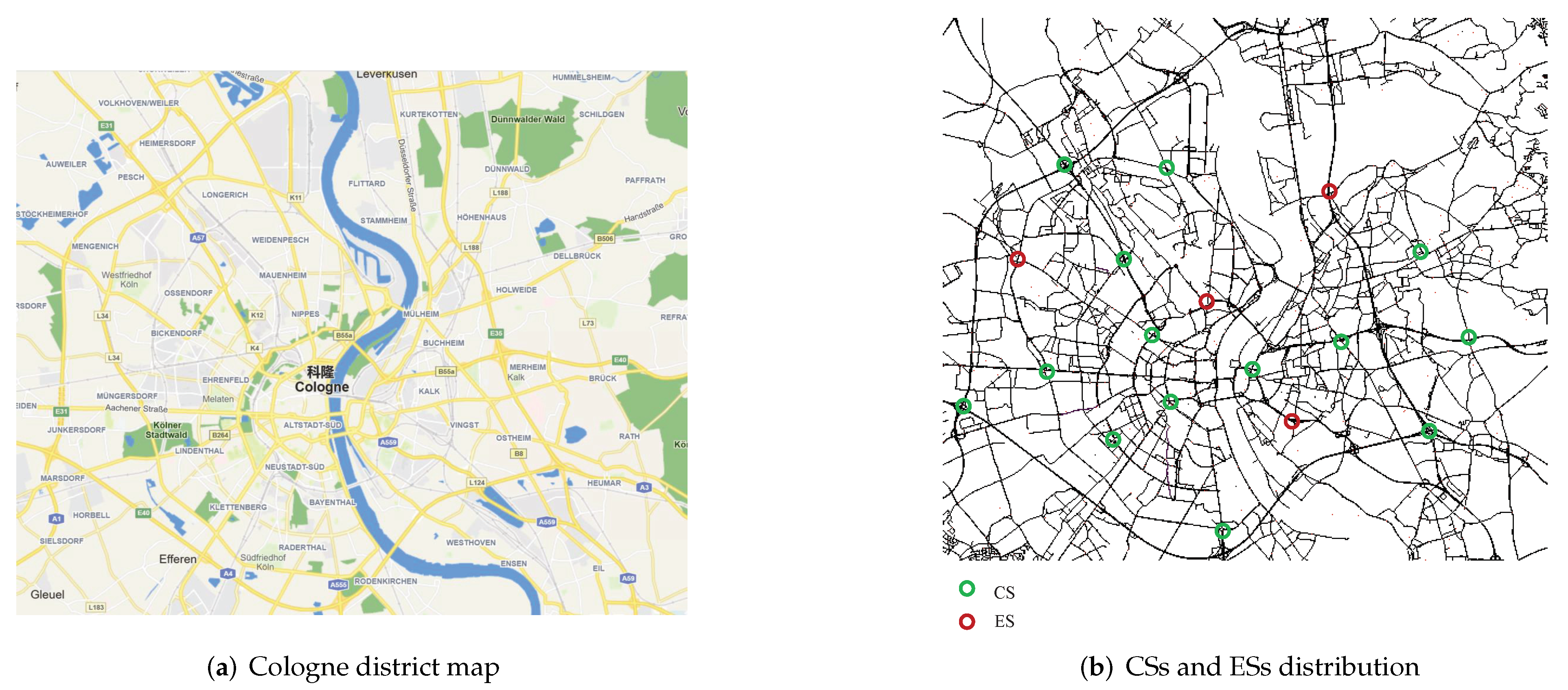
To carry out the simulation experiment, we select a real urban traffic scene in Cologne, Germany, and use Java open street map (JOSM) [46] to extract the main traffic network in Figure 4a. The number and distribution of charging infrastructures are shown in Figure 4b, where the number and distribution of CSs follow the information in [47]. ESs are randomly distributed, and considering that the deployment cost of ESs is higher than that of CSs, the number of ESs will be less than the number of CSs in the paper. The details of the map and other parameters required for the simulation are shown in Table 4.
We perform our evaluations using MATLAB and Simulation of Urban Mobility (SUMO), which is a traffic pattern and an open source, highly portable, microscopic, and continuous multi-modal traffic simulation. Our evaluations use data on all-day traffic conditions in the city of Cologne, Germany described by a TAPASCologne simulation scenario [48]. The capacity of the battery is 45 kWh based on Qirui Ruilin [49] and the maximum mileage of the battery capacity is 140 km. We initialize the experimental AEV with an SoC of 40% and set the arrival rate of vehicles at the charging infrastructure to 45 vehicles/hour. We set the small, medium, and large charging rates as 30 kWh, 50 kWh, and 70 kWh. The AEV is charged to at least 90%. Both MATLAB and SUMO are run on a Windows 11 computer with AMD R7 processor and 16 GB memory.

8.2. The TFD Thresholds Parameter Analysis

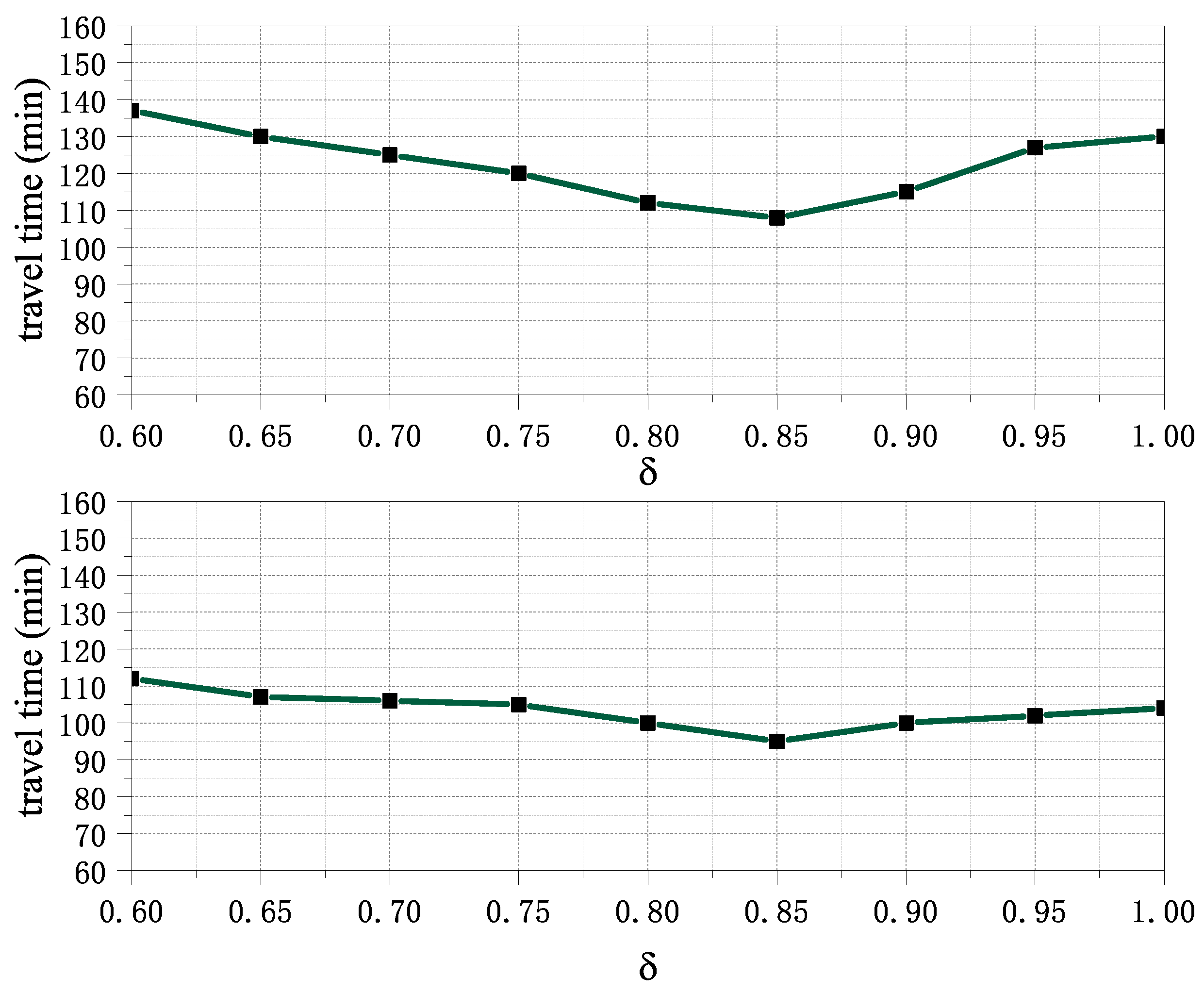
Since the size of δ affects the maximum road load and search range for path-planning, it has an impact on vehicle path optimization and the resulting travel time. Therefore, it is important to determine an appropriate value for δ to minimize travel time. To evaluate the impact of δ , δ is set to different values for further study. It starts at 0.6 and increases in small steps of 0.05. As shown in Figure 5, it is the travel time when δ takes different values from 7:00 a.m. to 8:00 a.m. and 2:00 p.m. to 3:00 p.m., respectively. If the value of δ is too small, the travel distance of the vehicle will increase due to detour, which will increase the travel time. However, if δ is too large, the number of vehicles on the road will increase, resulting in congestion, which will also increase the travel time. When δ = 0.85 , the travel time spent reaches a relatively minimum value. Therefore, we set δ to 0.85 in all evaluations.

8.3. The Evaluation of Communication Mode

The number of times AEVs obtain information is selected to evaluate the joint push–pull communication mode and performance comparison in simulation. This refers to the total number of times that all AEVs obtain information from RSUs. Considering the existing urban traffic conditions, the vehicle speed in the simulation is set randomly between 25 and 60 km/h. A 25-meter wireless communication range is selected for AEVs, and 250-meter communication range is applied for RSUs. The simulation is run with 50 vehicles for a duration of 1000 s. If all AEVs within the communication range of the intersection can receive the data packet sent by the RSU during the information update time, without considering packet loss. Figure 6 shows the number of times AEVs obtain information between push mode, pull mode, and joint push–pull mode. We can observe that as the update time interval increases, there is a decrease in the amount of information obtained through both the push and joint push–pull modes, while the pull mode remains relatively stable. This is because the longer update time intervals provide fewer opportunities for vehicles to receive information from the RSUs in the push and joint push–pull modes, while the pull mode relies on vehicles actively requesting information from the RSUs. In terms of performance, the push mode outperforms the pull mode, which can be attributed to the push mode’s ability to proactively provide information to vehicles. Additionally, the joint push–pull mode outperforms the push mode, as it combines the advantages of both push and pull modes. The point push–pull mode allows vehicles to receive up-to-date information from RSUs while also being able to actively request information when needed.

8.4. The Evaluation of Running Time

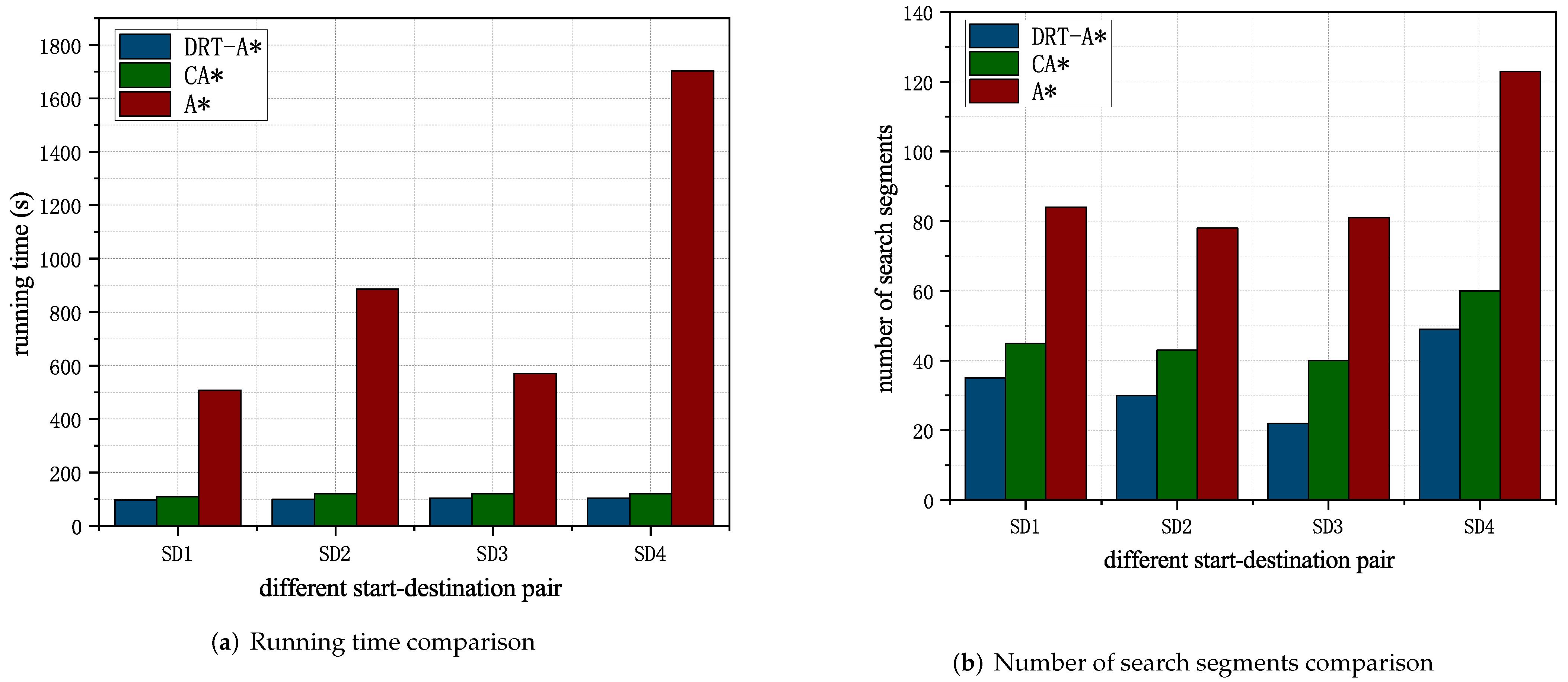
Figure 7a shows the running time comparison of different start–destination pairs between the A* algorithm, DRT-A* algorithm, and constrained A* shortest-path (CA*) algorithm in [28]. We set the starting nodes of these four start–destination pairs as the same starting node, but the destinations are different. We can observe that for four different start–destination pairs, the running time of the DRT-A* algorithm and CA* is less than the A* algorithm. In particular, when the distance from the start node to the destination becomes larger, compared with the A* algorithm, DRT-A* algorithm and CA* have more advantages in the running time. Figure 7b shows the comparison of the number of search segments between the A* algorithm, DRT-A* algorithm, and the CA*. We can observe that compared with the A* algorithm and CA*, the number of road segments searched by the DRT-A* algorithm is effectively reduced. As a result, the DRT-A* algorithm demonstrates superior performance compared to both the A* algorithm and the CA* algorithm in terms of reducing the search space and the number of road segments.

8.5. The Evaluation of Different Travel Start–Destination Time Cost

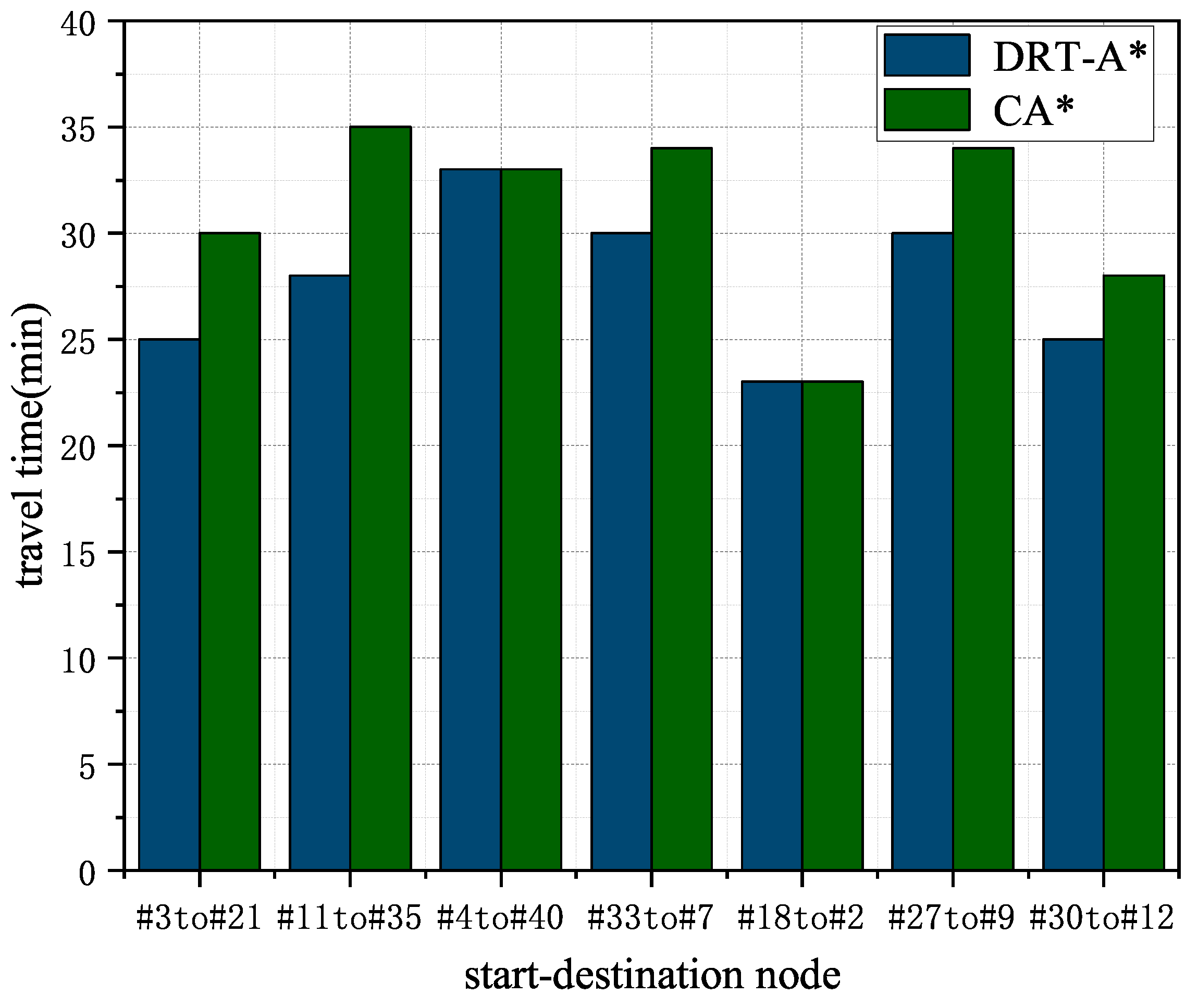
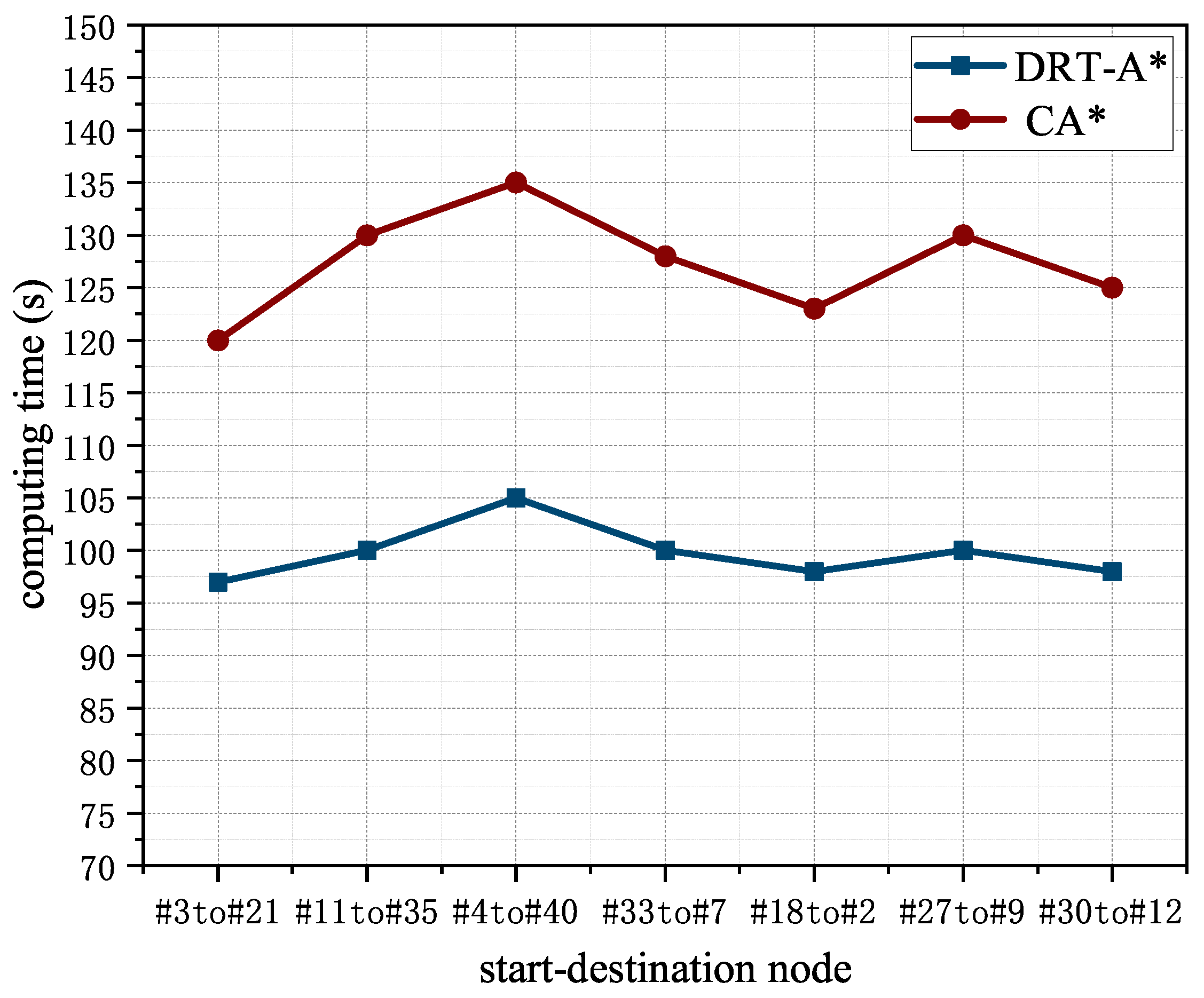
Figure 8 shows the comparison of AEV travel time for DRT-A* with CA* in different start–destination nodes. We can observe that the travel time with our DRT-A* algorithm is lower than or equal to the CA* algorithm. The DRT-A* algorithm can replan the original path based on updating real-time traffic information so that the traveling time estimation is much more accurate than the CA* algorithm. Furthermore, our DRT-A* algorithm considers the TFD constraint of the road segment in the path-planning, which can alleviate traffic congestion and reduce travel time. Each path can arrive at the destination, which verifies our proposed algorithm’s convergence. The average performance deviation between our proposed method and the CA* approach in terms of travel time is 2.87 min. Figure 9 shows the computation time for each of the instances. It can be observed that the computation time with our DRT-A* algorithm is lower than the CA* algorithm. The DRT-A* algorithm improved the average performance by 27.8% compared to the CA* algorithm, and the computation time for each instance is very close, with a difference of less than 8% between the maximum and minimum computation times. The results demonstrate the efficiency of the DRT-A* algorithm in finding optimal paths for AEVs in urban traffic networks while reducing travel time and computation time.
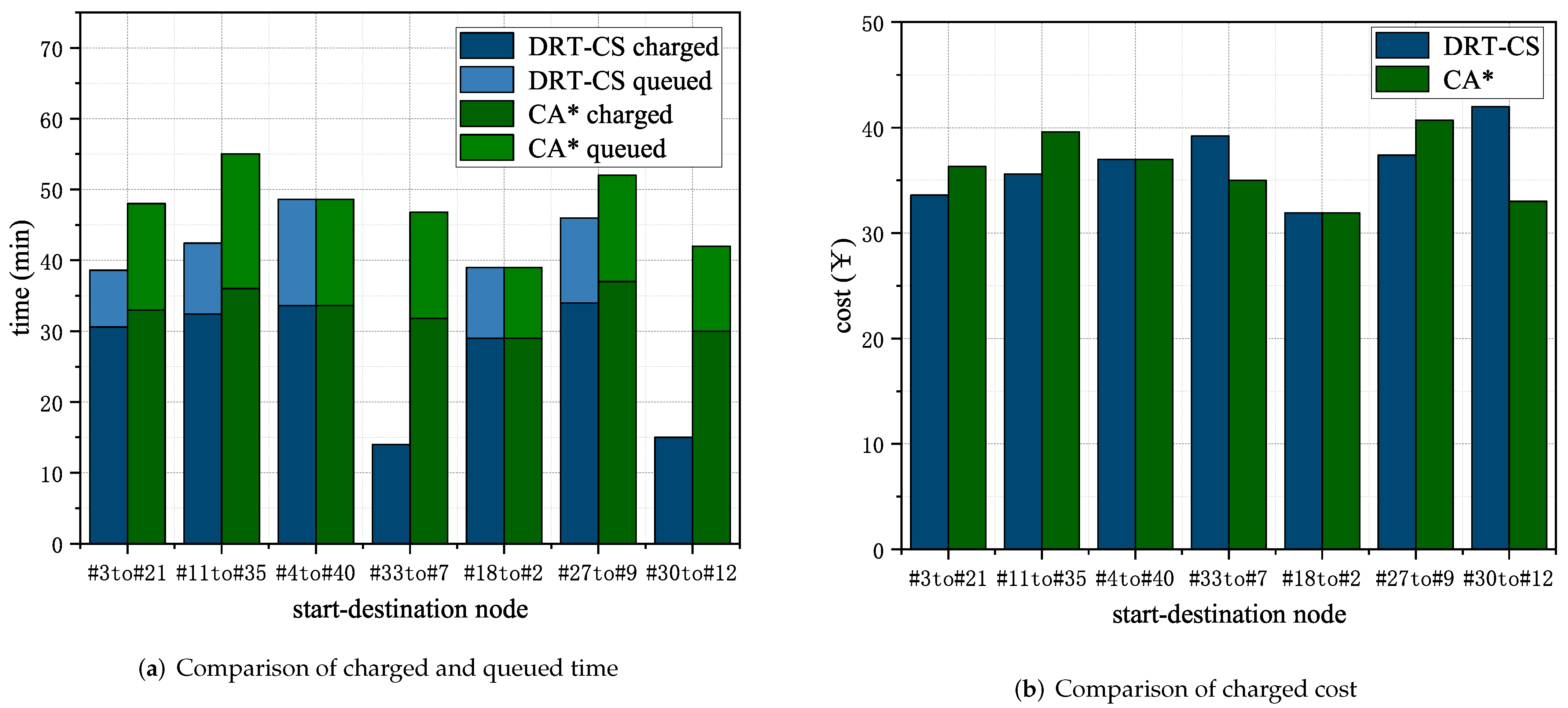
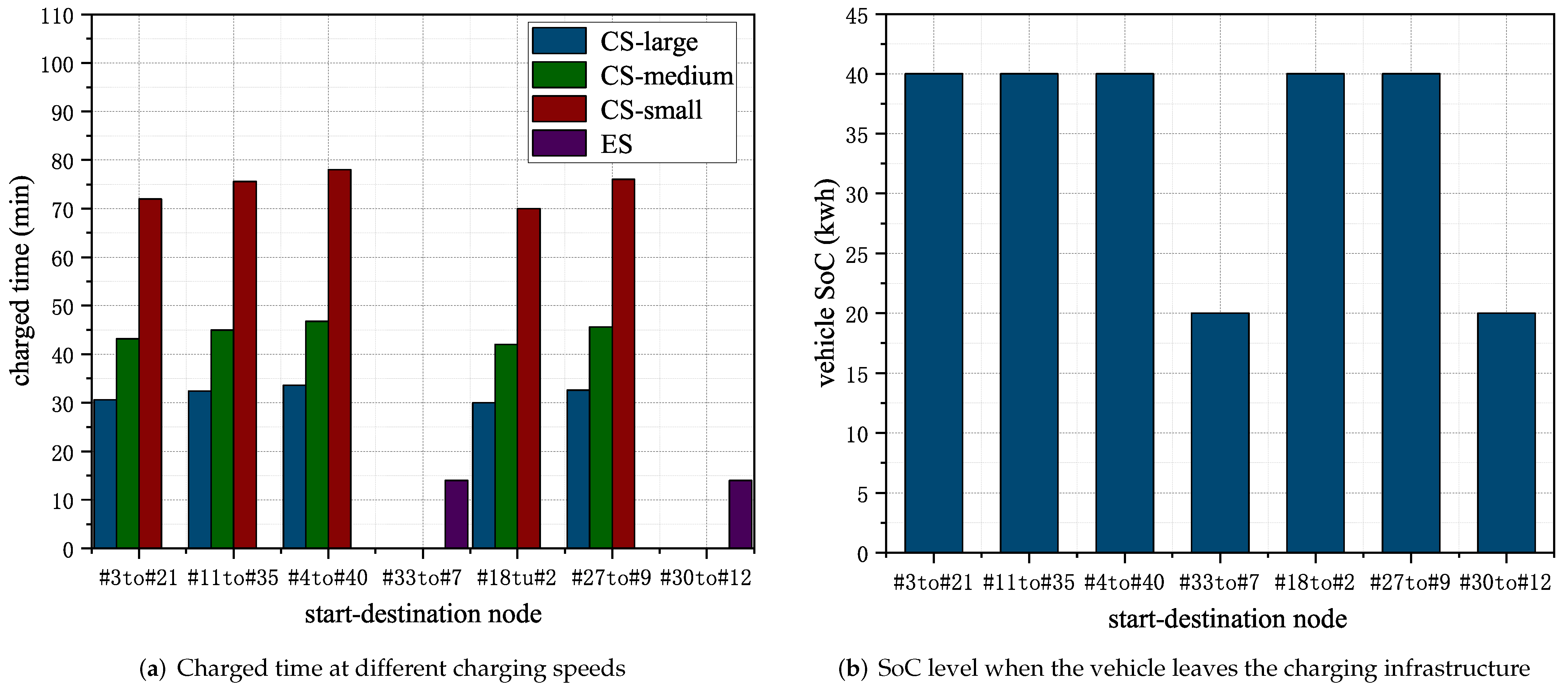
Figure 10a shows the comparison of AEV charged time and queued time for DRT-CS with CA* in different start–destination pairs. The charged time obtained here is when the charging rate is 70 kWh. We can observe that the queue time with our DRT-A* algorithm is lower than or equal to CA* algorithm in start–destination # 3 t o # 21 , # 11 t o # 35 , # 4 t o # 40 , # 18 t o # 2 and # 27 t o # 9 . The DRT-CS algorithm can select the charging infrastructure based on updating the number of queued vehicles and the service status of charging slots so that the queue time estimation is much more accurate. The travel path planned by the CA* algorithm takes more time compared to the DRT-A* algorithm in start–destination # 3 t o # 21 , # 11 t o # 35 and # 27 t o # 9 , which causes AEVs to consume more charge. As a result, when all AEVs are charged to 90% of their battery capacity, the charging time will be longer to compensate for the higher energy consumption. In DRT-CS, we can observe that there is no queued time in start–destination # 33 t o # 7 , # 30 t o # 12 , and the charged time is also relatively short. This is because the vehicle chooses to charge at the ES, and the charging capacity does not reach 90%. The average performance deviation between our proposed method and the CA* approach in terms of charging time and queuing time is 6.11 min and 4.85 min, respectively. Figure 10b shows the charged cost of the vehicle. The unit charging price of charge station is RMB 1.1, and the unit charging price of ES is RMB 2.8. In the travel of start–destination # 3 t o # 21 , # 11 t o # 35 and # 27 t o # 9 , when the AEV’s battery is charged to 90% capacity, AEV will require more charge with CA* algorithm compared to the DRT-CS algorithm. As a result, the AEV needs to pay for more charge with the same unit charging price. The mobile charging service provided by ES for AEV does not require queued time compared with charge station. However, due to the length limitation of ES, the charged capacity of vehicles may not reach 90%, and the charged cost will be higher than charge station.
Figure 11a shows the charged time of the vehicle at different charged speeds in the selected charging infrastructure. We can observe that the charged time required in ES in start–destination # 33 t o # 7 and # 30 t o # 12 is less than the minimum charging time in charge station, because the charging capacity in ES is less than that in charge station. Choosing a charging slot with a faster charging rate reduces the charging time required but increases the charging cost. Therefore, the vehicle can select a charging slot based on its individual needs. Figure 11b shows the SoC when the vehicle leaves the charging infrastructure. Due to the limited length of the ES, it may not be able to charge a vehicle up to 90%. Nevertheless, its flexible charging mode provides more convenient charging opportunities for vehicles in urgent need of power replenishment or those close to their destination.

8.6. The Evaluation of Path-Planning and Charging Selection

In general, traffic conditions are subject to change over time due to factors such as road construction, maintenance, or unexpected vehicle accidents, which may cause road congestion. Likewise, the service status of charging infrastructures can vary over time, a significant number of AEVs charging may result in long queuing times.
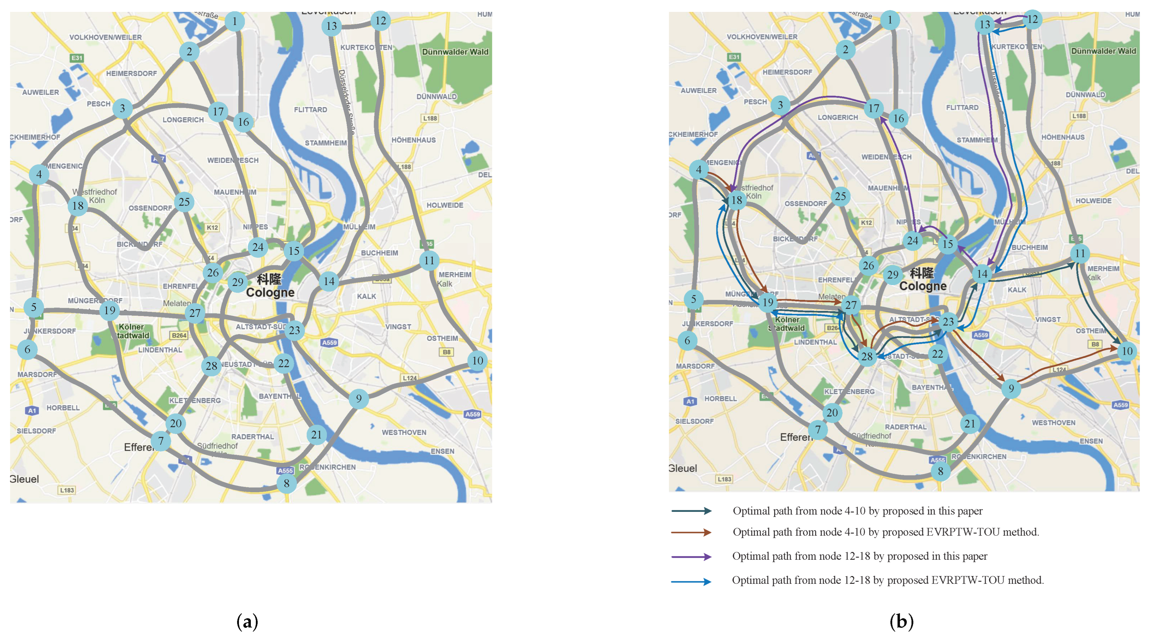
We simplify the transportation network in Cologne, Germany, as illustrated in Figure 12a. The transportation network comprises 29 road intersections, with 2 CSs located at nodes 17 and 28. Traffic and charging infrastructure data obtained by AEVs includes the number of vehicles per route, the service status of charging slots, the number of AEVs queuing, and the arrival rate of AEVs. Suppose there are charging demands at intersections 4 and 12, and their destinations are nodes 10 and 18, respectively.
The dynamic changes in the traffic conditions and service status of charging infrastructures require the navigation approach and charging selection to be adaptive. The real-time information is updated by joint push–pull mode. The optimal path for AEVs is rescheduled with real-time data according to their current locations and real-time system conditions. Due to heavy road congestion on the road segments ( 23 , 9 ) and ( 9 , 10 ) . AEV 4 reschedules its path from 4-18-19-27-28-23-9-10 to 4-18-19-27-28-23-14-11-10. Since c s 28 is now fully loaded, AEV 12 is navigated to charge at c s 17 . The schedule navigation results for AEV 4 and 12 proposed in this paper and the electric-vehicle routing problem with time windows and time of use prices (EVRPTW-TOU) in [29] are shown in Figure 12b. The results demonstrate that the proposed dynamic optimization can reschedule the optimal path and charging selection promptly in response to system parameter variations.

9. Conclusions

The state of charge is a critical factor in ensuring any AEV reaches its destination. Hence, in addition to the path-planning problem, the AEV must also consider the charging problem. This paper addresses dynamic path optimization with a charging problem to minimize travel and charging costs based on real-time information. In the charging problem, we considered both CSs and ESs as charging sources. First, we proposed a joint push–pull communication mode to obtain real-time traffic conditions and charging infrastructure service status information. Based on this information, we formulated a dynamic optimization problem to minimize travel and charging costs. However, solving this problem directly is difficult, so we converted the original dynamic optimization problem into individual optimization problems. Moreover, we proposed the DRT-A* algorithm to solve the dynamic path-optimization problem and the DRT-CS algorithm to solve the charging problem based on dynamic path optimization. The comparative experimental results show that the proposed dynamic optimization algorithm outperforms the CA* algorithm when the travel time and queuing time are used as performance metrics. Moreover, our proposed algorithm also has better path-optimization performance in the general scenario, compared to the EVRPTW-TOU method. As our algorithm takes into account dynamic transportation networks, it alleviates both traffic and charging congestion and improves vehicles’ efficient operation. In future work, we will focus on addressing communication challenges related to obtaining real-time network information, specifically studying the charging communication protocol in detail to provide safe and efficient communication for vehicle charging. Overall, the proposed approach can pave the way for more efficient and cost-effective routing and charging strategies for autonomous electric vehicles.

Author Contributions

Conceptualization, Q.T. and D.L.; methodology, Q.T. and D.L.; software, Q.T.; validation, Q.T.; formal analysis, Q.T., D.L., Y.Z. and X.C.; investigation, Q.T.; resources, Q.T.; data curation, Q.T.; writing—original draft preparation, Q.T.; writing—review and editing, Q.T., D.L., Y.Z. and X.C.; visualization, Q.T.; supervision, Q.T., D.L. and Y.Z. All authors have read and agreed to the published version of the manuscript.

Funding

This work is supported by NSF of China under Grant No.61772130, No. 71171045, and No. 61901104; the Innovation Program of Shanghai Municipal Education Commission, China under Grant No.14YZ130; the International S&T Cooperation Program of Shanghai Science and Technology Commission, China under Grant No. 15220710600.

Institutional Review Board Statement

Not applicable.

Informed Consent Statement

Not applicable.

Data Availability Statement

Not applicable.

Conflicts of Interest

The authors declare no conflict of interest.

References

  1. Iacobucci, R.; McLellan, B.; Tezuka, T. Modeling shared autonomous electric vehicles: Potential for transport and power grid integration. Energy 2018, 158, 148–163. [Google Scholar] [CrossRef]
  2. Wu, J.; Liao, H.; Wang, J.W.; Chen, T. The role of environmental concern in the public acceptance of autonomous electric vehicles: A survey from China. Transp. Res. Part F Traffic Psychol. Behav. 2019, 60, 37–46. [Google Scholar] [CrossRef]
  3. Huang, T.; Pan, H.; Sun, W.; Gao, H. Sine resistance network-based motion planning approach for autonomous electric vehicles in dynamic environments. IEEE Trans. Transp. Electrif. 2022, 8, 2862–2873. [Google Scholar] [CrossRef]
  4. Hwang, M.H.; Lee, G.S.; Kim, E.; Kim, H.W.; Yoon, S.; Talluri, T.; Cha, H.R. Regenerative Braking Control Strategy Based on AI Algorithm to Improve Driving Comfort of Autonomous Vehicles. Appl. Sci. 2023, 13, 946. [Google Scholar] [CrossRef]
  5. Ercan, T.; Onat, N.C.; Keya, N.; Tatari, O.; Eluru, N.; Kucukvar, M. Autonomous electric vehicles can reduce carbon emissions and air pollution in cities. Transp. Res. Part D Transp. Environ. 2022, 112, 103472. [Google Scholar] [CrossRef]
  6. Vdovic, H.; Babic, J.; Podobnik, V. Automotive software in connected and autonomous electric vehicles: A review. IEEE Access 2019, 7, 166365–166379. [Google Scholar] [CrossRef]
  7. Cao, Y.; Li, D.; Zhang, Y.; Chen, X. Joint optimization of delay-tolerant autonomous electric vehicles charge scheduling and station battery degradation. IEEE Internet Things J. 2020, 7, 8590–8599. [Google Scholar] [CrossRef]
  8. Yao, C.; Chen, S.; Yang, Z. Joint routing and charging problem of multiple electric vehicles: A fast optimization algorithm. IEEE Trans. Intell. Transp. Syst. 2021, 23, 8184–8193. [Google Scholar] [CrossRef]
  9. Liu, H.; Yin, W.; Yuan, X.; Niu, M. Reserving charging decision-making model and route plan for electric vehicles considering information of traffic and charging station. Sustainability 2018, 10, 1324. [Google Scholar] [CrossRef]
  10. Li, M.; Deng, Y.; Yang, H.; Lai, M.; Dong, Z. Electric Vehicle Route Selection and Charging Navigation Strategy Considering Time-of-Use Pric. South. Power Syst. Technol 2016, 10, 61–66. [Google Scholar]
  11. Xing, Q.; Chen, Z.; Leng, Z.; Lu, Y.; Liu, Y. Route Planning and Charging Navigation Strategy for Electric Vehicles Based on Real-time Traffic Information. Proc. CSEE 2020, 40, 534–550. [Google Scholar]
  12. Luo, Y.; Zhu, T.; Wan, S.; Zhang, S.; Li, K. Optimal charging scheduling for large-scale EV (electric vehicle) deployment based on the interaction of the smart-grid and intelligent-transport systems. Energy 2016, 97, 359–368. [Google Scholar] [CrossRef]
  13. Liu, L.; Zhang, Y.; Feng, H. Research on dynamic energy saving path planning algorithm based on real-time traffic information. In Proceedings of the 2016 4th International Conference on Advanced Materials and Information Technology Processing (AMITP 2016), Guilin, China, 24–25 September 2016; Atlantis Press: Amsterdam, The Netherlands, 2016; pp. 314–319. [Google Scholar]
  14. Li, G.; Sun, Q.; Boukhatem, L.; Wu, J.; Yang, J. Intelligent vehicle-to-vehicle charging navigation for mobile electric vehicles via VANET-based communication. IEEE Access 2019, 7, 170888–170906. [Google Scholar] [CrossRef]
  15. Wang, M.; Liang, H.; Deng, R.; Zhang, R.; Shen, X.S. VANET based online charging strategy for electric vehicles. In Proceedings of the 2013 IEEE Global Communications Conference (GLOBECOM), Atlanta, GA, USA, 9–13 December 2013; pp. 4804–4809. [Google Scholar]
  16. Bi, X.; Gao, D.; Yang, M. A reinforcement learning-based routing protocol for clustered EV-VANET. In Proceedings of the 2020 IEEE 5th Information Technology and Mechatronics Engineering Conference (ITOEC), Chongqing, China, 12–14 June 2020; pp. 1769–1773. [Google Scholar]
  17. Liu, C.; Zhou, M.; Wu, J.; Long, C.; Wang, Y. Electric vehicles en-route charging navigation systems: Joint charging and routing optimization. IEEE Trans. Control Syst. Technol. 2017, 27, 906–914. [Google Scholar] [CrossRef]
  18. Liu, P.; Wang, C.; Hu, J.; Fu, T.; Cheng, N.; Zhang, N.; Shen, X. Joint Route Selection and Charging Discharging Scheduling of EVs in V2G Energy Network. IEEE Trans. Veh. Technol. 2020, 69, 10630–10641. [Google Scholar] [CrossRef]
  19. Liu, J.; Lin, G.; Huang, S.; Zhou, Y.; Rehtanz, C.; Li, Y. Collaborative EV routing and charging scheduling with power distribution and traffic networks interaction. IEEE Trans. Power Syst. 2022, 37, 3923–3936. [Google Scholar] [CrossRef]
  20. Lam, A.Y.; Leung, K.C.; Li, V.O. Vehicular energy network. IEEE Trans. Transp. Electrif. 2017, 3, 392–404. [Google Scholar] [CrossRef]
  21. Fu, T.; Wang, C.; Cheng, N. Deep-learning-based joint optimization of renewable energy storage and routing in vehicular energy network. IEEE Internet Things J. 2020, 7, 6229–6241. [Google Scholar] [CrossRef]
  22. Manshadi, S.D.; Khodayar, M.E.; Abdelghany, K.; Üster, H. Wireless charging of electric vehicles in electricity and transportation networks. IEEE Trans. Smart Grid 2017, 9, 4503–4512. [Google Scholar] [CrossRef]
  23. Duell, M.; Gardner, L.M.; Waller, S.T. Policy implications of incorporating distance constrained electric vehicles into the traffic network design problem. Transp. Lett. 2018, 10, 144–158. [Google Scholar] [CrossRef]
  24. Wang, Y.; Jiang, J.; Mu, T. Context-aware and energy-driven route optimization for fully electric vehicles via crowdsourcing. IEEE Trans. Intell. Transp. Syst. 2013, 14, 1331–1345. [Google Scholar] [CrossRef]
  25. Yang, H.; Deng, Y.; Qiu, J.; Li, M.; Lai, M.; Dong, Z.Y. Electric vehicle route selection and charging navigation strategy based on crowd sensing. IEEE Trans. Ind. Inform. 2017, 13, 2214–2226. [Google Scholar] [CrossRef]
  26. Ding, D.; Li, J.; Tu, P.; Wang, H.; Cao, T.; Zhang, F. Electric vehicle charging warning and path planning method based on spark. IEEE Access 2020, 8, 8543–8553. [Google Scholar] [CrossRef]
  27. Schoenberg, S.; Dressler, F. Reducing waiting times at charging stations with adaptive electric vehicle route planning. IEEE Trans. Intell. Veh. 2022, 8, 95–107. [Google Scholar] [CrossRef]
  28. Del Razo, V.; Jacobsen, H.A. Smart charging schedules for highway travel with electric vehicles. IEEE Trans. Transp. Electrif. 2016, 2, 160–173. [Google Scholar] [CrossRef]
  29. Ferro, G.; Paolucci, M.; Robba, M. Optimal charging and routing of electric vehicles with power constraints and time-of-use energy prices. IEEE Trans. Veh. Technol. 2020, 69, 14436–14447. [Google Scholar] [CrossRef]
  30. Gusrialdi, A.; Qu, Z.; Simaan, M.A. Distributed scheduling and cooperative control for charging of electric vehicles at highway service stations. IEEE Trans. Intell. Transp. Syst. 2017, 18, 2713–2727. [Google Scholar] [CrossRef]
  31. Weist, M. A Transport Simulation-Based Analysis of Optimal Long-Distance Route Planning for Battery Electric Vehicles in Germany. Ph.D Thesis, Georgia Institute of Technology, Atlanta, GA, USA, 2021. [Google Scholar]
  32. Embleton, N.D.; Munteanu, A.; Ho, E. Northumbria Research Link. IEEE Trans. Neural Syst. Rehabil. Eng. 2022, 30, 8–19. [Google Scholar]
  33. Alqahtani, M.; Hu, M. Dynamic energy scheduling and routing of multiple electric vehicles using deep reinforcement learning. Energy 2022, 244, 122626. [Google Scholar] [CrossRef]
  34. Subramanian, V.; Feijoo, F.; Sankaranarayanan, S.; Melendez, K.; Das, T.K. A bilevel conic optimization model for routing and charging of EV fleets serving long distance delivery networks. Energy 2022, 251, 123808. [Google Scholar] [CrossRef]
  35. Guo, C.; Li, D.; Zhang, G.; Zhai, M. Real-time path planning in urban area via vanet-assisted traffic information sharing. IEEE Trans. Veh. Technol. 2018, 67, 5635–5649. [Google Scholar] [CrossRef]
  36. Umoren, I.A.; Shakir, M.Z.; Tabassum, H. Resource efficient vehicle-to-grid (V2G) communication systems for electric vehicle enabled microgrids. IEEE Trans. Intell. Transp. Syst. 2020, 22, 4171–4180. [Google Scholar] [CrossRef]
  37. Juvva, K.; Rajkumar, R. A Real-Time Push-Pull Communications Model for Distributed Real-Time and Multimedia Systems; Technical Report; Carnegie-Mellon Univ Pittsburgh Pa Dept of Computer Science: Pittsburgh, PA, USA, 1999. [Google Scholar]
  38. Naderi, M.; Zargari, F.; Sadatpour, V.; Ghanbari, M. A 3-parameter routing cost function for improving opportunistic routing performance in VANETs. Wirel. Pers. Commun. 2017, 97, 109–123. [Google Scholar] [CrossRef]
  39. Patel, A.; Jinwala, D. A reputation-based RPL protocol to detect selective forwarding attack in Internet of Things. Int. J. Commun. Syst. 2022, 35, e5007. [Google Scholar] [CrossRef]
  40. Skabardonis, A.; Dowling, R. Improved speed-flow relationships for planning applications. Transp. Res. Rec. 1997, 1572, 18–23. [Google Scholar] [CrossRef]
  41. Zadobrischi, E.; Cosovanu, L.M.; Dimian, M. Traffic flow density model and dynamic traffic congestion model simulation based on practice case with vehicle network and system traffic intelligent communication. Symmetry 2020, 12, 1172. [Google Scholar] [CrossRef]
  42. Zhang, Y.; You, P.; Cai, L. Optimal charging scheduling by pricing for EV charging station with dual charging modes. IEEE Trans. Intell. Transp. Syst. 2018, 20, 3386–3396. [Google Scholar] [CrossRef]
  43. Wang, H.; Cai, X.; Zhang, Y.; Liu, A.; Huang, P.; Li, C. Driving on GWB: Energy-efficiency-driven route optimisation for EVs. IET Intell. Transp. Syst. 2019, 14, 25–35. [Google Scholar] [CrossRef]
  44. Arnott, R.; Rave, T.; Schöb, R. Alleviating Urban Traffic Congestion; MIT Press Books: Cambridge, MA, USA, 2005; Volume 1. [Google Scholar]
  45. Zeng, W.; Church, R.L. Finding shortest paths on real road networks: The case for A. Int. J. Geogr. Inf. Sci. 2009, 23, 531–543. [Google Scholar] [CrossRef]
  46. Huber, S.; Rust, C. Calculate travel time and distance with OpenStreetMap data using the Open Source Routing Machine (OSRM). Stata J. 2016, 16, 416–423. [Google Scholar] [CrossRef]
  47. Mortimer, B.J.; Hecht, C.; Goldbeck, R.; Sauer, D.U.; De Doncker, R.W. Electric Vehicle Public Charging Infrastructure Planning Using Real-World Charging Data. World Electr. Veh. J. 2022, 13, 94. [Google Scholar] [CrossRef]
  48. Sumo. Traffic Data. 2015. Available online: https://sourceforge.net/projects/sumo/files/traffic_data/scenarios/TAPASCologne/ (accessed on 26 October 2022).
  49. Ruilin, Q. Vehicle Configuration Information. 2022. Available online: https://www.tyncar.com/Q/qirui_rq_185.html (accessed on 25 October 2022).
Figure 1. Illustration of the transportation network architecture.
Applsci 13 05476 g001
Figure 2. Procedures of dynamic path-planning and charging selection system.
Applsci 13 05476 g002
Figure 3. Illustration of intersection communication range between vehicle and RSU.
Applsci 13 05476 g003
Figure 4. Illustration of simulation scenario.
Applsci 13 05476 g004
Figure 5. Comparison of travel time for different TFDs.
Applsci 13 05476 g005
Figure 6. Comparison of the number of times AEVs obtain data packet.
Applsci 13 05476 g006
Figure 7. Comparison between A*, CA* and DRT-A*.
Applsci 13 05476 g007
Figure 8. Travel time comparison between CA* and DRT-A*.
Applsci 13 05476 g008
Figure 9. Computing time.
Applsci 13 05476 g009
Figure 10. Comparison between DRT-CS, CA*.
Applsci 13 05476 g010
Figure 11. Charged time and SoC level.
Applsci 13 05476 g011
Figure 12. Simplified transportation network and navigation path. (a) Illustration of a 29-intersection transportation system; (b) navigation path.
Applsci 13 05476 g012
Table 1. Characteristics in previous works.
Article ReferenceEnergy CostTravel TimeWaiting TimeCharging LocationBattery CapacityDynamic OptimizationDistributed Decision
Liu et al. [17]×××× ××
Liu et al. [18]× ×××
Liu et al. [19]× ××
Manshadi et al. [22]×× ×
Liu et al. [23]×× ×
Wang et al. [24]×× ××
Yang et al. [25] ×× ×
Ding et al. [26]××××× ×
Schoenberg et al. [27] ××× ××
Del Razo et al. [28] ××××××
Ferro et al. [29]×× ×× ×
Gusrialdi et al. [30]× × ×
Weist et al. [31]××××××
Embleton et al. [32] ×
Alqahtani et al. [33] ×××
Subramanian et al. [34]×× ××
our work in this paper×××××××
Table 2. Notations.
Table 2. Notations.
NotationDescription
V Road node set in graph G.
V c s Set of charging stations.
c s i Charging station at road node i.
Θ Road section set in graph G.
Θ e ES set in graph G.
t i k Time for AEV k to reach node i.
t i k Time for AEV k to leave node i.
τ c s i k , c AEV k charging time at c s i .
τ c s i k , w AEV k queuing time at c s i .
τ i j k , r AEV k travel time on segment ( i , j ) .
E i j k AEV k energy consumption on segment ( i , j ) .
C i k AEV k SoC at road node i.
Ω The SoC that AEV needs to charge.
η i j Traffic flow density on segment ( i , j ) .
L i j Length of road segment ( i , j ) .
Q i j m a x Maximum number of AEVs on segment ( i , j ) .
Q i j ( t ) The number of AEVs on segment ( i , j ) at t.
L S k h The variation in the position between two vehicles k and h.
D k h The distance difference between the vehicle k and h to the R.
S k h The total number of data packets sent from vehicle k to vehicle h.
F k h The total number of data packets forwarded by vehicle k to vehicle h.
M k h The total number of packets lost by vehicle k to vehicle h.
Table 3. Nomenclature.
AbbreviationDescription
AEVautonomous electric vehicle
VANETsvehicular ad hoc networks
RSUroadside unit
V2Vvehicle-to-vehicle
V2Rvehicle to roadside unit
V2Gvehicle to gird (charging infrastructure)
CScharging station
ESenergy segment
TFDtraffic flow density
SoCstate of charge
DRT-A*dynamic real-time A*
DRT-CSdynamic real-time charging selection
Table 4. Simulation Parameters.
Simulation ParametersValue
Network area20 (km 2 )
AEV speed(V)25–60 (km/h)
AEV mass (M)1200 kg
Acceleration of gravity (g)9.8 m/s 2
Rolling friction coefficient ( f r )0.009
Air density ( ρ )1.2 kg/m 3
Coefficient of air resistance ( φ )0.335
Frontal area (A)2 m 2
Road slope ( θ )0 deg
Weight parameters α = 0.5 , β = 6
w t = 0.5 , w e = 0.5
Disclaimer/Publisher’s Note: The statements, opinions and data contained in all publications are solely those of the individual author(s) and contributor(s) and not of MDPI and/or the editor(s). MDPI and/or the editor(s) disclaim responsibility for any injury to people or property resulting from any ideas, methods, instructions or products referred to in the content.