Featured Application
An open bite can be corrected with a mid-palatal TAD and an intrusion TPA. Clinicians can select the anteroposterior position of TAD to obtain the posterior intrusion or total intrusion.
Abstract
Mechanics using a mid-palatal temporary anchorage device (TAD) and an intrusion transpalatal arch (TPA) were applied to correct the open bites. Two different intrusion patterns could be obtained according to the anteroposterior position of mid-palatal TADs. When the TAD was placed posterior to the first molar, the posterior teeth were intruded (“posterior intrusion”), and the open bite was corrected efficiently. This is commonly used in most open bites. However, sometimes, in an open bite with a gummy smile, intrusion of the maxillary anterior teeth, as well as the posterior teeth, may be necessary. In this case, the TAD was placed anterior to the first molar, and a “total intrusion” was obtained, including anterior intrusion. In conclusion, the intrusion pattern of the maxillary teeth differs depending on the anterior–posterior position of the mid-palatal TAD, necessitating posterior intrusion or Total intrusion.
1. Introduction
Attempts to treat an open bite with molar intrusion using a temporary anchorage device (TAD) have been reported since the early 2000s [1,2,3,4]. Figure 1 shows an open-bite case treated by intruding maxillary molars with buccal screws between the roots of the maxillary first and second molars. Molar intrusion resulted in counterclockwise rotation of the mandible, a lower anterior facial height decrease, and resolution of the retrusive chin (Figure 2). This method made it possible to get a maxillary impaction effect orthodontically without orthognathic surgery. Screw-type TADs, which are convenient for placement and removal, became popular [3,4]. Buccal TADs were placed between the maxillary first and second molar roots. Molar intrusion using buccal TADs showed buccal tipping of molars as a side-effect, which was controlled by the palatal inter-radicular TADs (Figure 1G,H and Figure 3A), a mid-palatal TAD [5], or a transpalatal arch (TPA) (Figure 3B) [6]. However, there were some disadvantages. The inter-radicular space between the maxillary first and second molar is usually narrow, making it difficult to place screws. Moreover, it is not uncommon for buccal inter-radicular TADs to fall out during posterior intrusion.
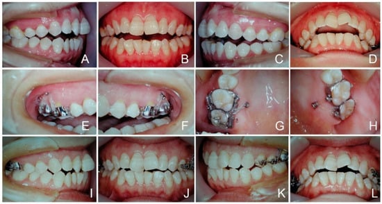
Figure 1.
Case 1. Maxillary molars were intruded with buccal and palatal interradicular TADs. (A–D) Initial photos. Only four maxillary molars were occluding. (E,F), Buccal view. (G,H), Palatal view. TADs were placed between the first and second molars. These teeth were intruded with power chains. (I–L), After 4 months, as the maxillary four molars were intruded, both overbite and overjet decreased.
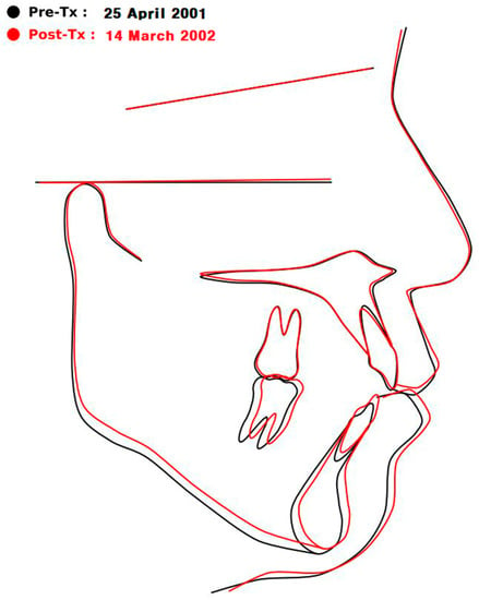
Figure 2.
Case 1. The black line is before, and the red line is after the intrusion of the maxillary first and second molars. As only four upper molars were intruded, the mandible was rotated counterclockwise, and the pogonion protruded. In the early 2000s, it was good news that these skeletal changes were possible only through the intrusion of maxillary molars using TADs without maxillary impaction surgery.
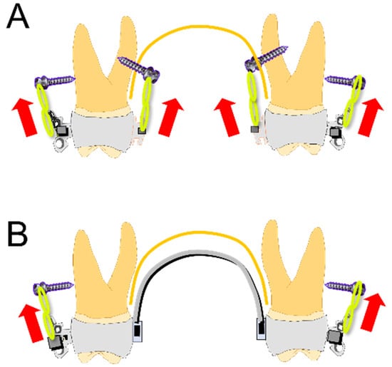
Figure 3.
Molar intrusion methods with buccal TADs. (A) The method of Case 1 used four TADs between the roots of upper posterior teeth. The palatal screws were added to prevent buccal tipping caused by the buccal TADs. (B) The method uses a TPA with crown lingual torque [3,4]. The TPA prevents buccal tipping caused by the buccal TADs.
Molar intrusion using plates was also introduced in the early 2000s [1,2]. It has the advantage that the failure rate is lower than the buccal TADs. However, the molar intrusion method using plates was limited to exceptional cases due to the inconvenience of implantation and removal surgery [7,8,9], although they had a higher survival rate than the TADs.
The buccal screw-type TADs (Figure 3A,B) are more convenient than plates which need surgery for placement or removal [7,8,9]. Nevertheless, it is hard to find good indications because buccal inter-radicular spaces between the first and second molars are usually too narrow to place them safely without root trauma. The other disadvantage is that they frequently fail as the posterior teeth intrude. As the posterior teeth intrude, the screws become closer to the alveolar crests, whose areas are easily bent or traumatized by the occluding forces.
At first, Paik et al. used a mid-palatal TAD to intrude the maxillary teeth in a mouth protrusion case accompanying the maxillary vertical excess without an open bite [10,11]. They used a TPA to transfer the intruding force to the first molars and to prevent lingual tipping of intruding molars. This method was modified by Kim to treat open-bite patients [12], which became extensively used in various open-bite cases because of its safety, simplicity, and stability [13]. This article aims to introduce open-bite correction with a mid-palatal TAD combined with an intrusion TPA and to explain its biomechanics, especially the different effects of the anteroposterior position of TAD.
2. Mechanics of Open-Bite Correction Using a Mid-Palatal TAD Combined with an Intrusion TPA
Figure 4 shows the structure of the posterior intrusion method using a mid-palatal TAD and an intrusion TPA. After leveling up to 0.019 × 0.025 stainless steel (ss), a mid-palatal TAD is placed on the center of a line connecting the contact points of the first and second molars. The intrusion TPA is removable, as it is necessary to adjust during the intrusion procedure. The palatal sheaths (tooth 17–16, 728-016-00/tooth 26–27, 728-017-00, Dentaurum, Langhorne, PA, USA) are welded to the first molar bands. It is recommended to use the maxillary first molar bands over bonding because sometimes, during the removal of the TPA for adjustment, the bonded sheath may fail. On the TPA, two hooks are soldered near the gingival margin. The gap (about 4–5 mm) between the palatal mucosa and the TPA is required to avoid mucosal impingement during the intrusion (Figure 4B). A power chain is applied tightly from the head of the screw to the hooks of the TPA. Case 2 (Figure 5 and Figure 6) shows these mechanics. If the second molars require further intrusion, accessory hooks can be attached for the power chain traction of the second molars (Figure 5H). At the detailing stage after intruding posterior teeth, final occlusion is obtained by wire bending adjustment with intermaxillary elastic bands such as Class II 5/16″ 6 oz and up/down 3/16″ 6 oz. The L-shaped loops between maxillary lateral incisors and canines on the 0.019 × 0.025 ss are used routinely at the space-closing and detailing stages for three purposes: to hook elastic bands, to control labio-lingual/vertical alignment of the lateral incisor and canine, and to apply torque for four incisors. Lateral cephalometric tracing showed the skeleto-dental changes, maxillary molar intrusion, and counterclockwise rotation of the mandible (Figure 6).
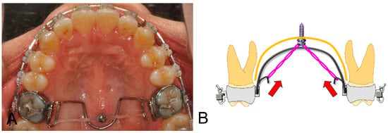
Figure 4.
Mid-palatal TAD (1.6 mm × 6.0 mm, JA type, RMO, Inc., Denver, CO, USA) and intrusion TPA (0.9 mm stainless-steel round wire). A mid-palatal TAD is placed on the center of a line connecting the contact points of the first and second molars. The main archwire is 0.019 × 0.025 ss with a slight crown buccal torque. There are two hooks on the intrusion TPA for the power chains. A stretched power chain is ligated to the screw head with a steel ligature and is hung on the hooks soldered to TPA. (A) is the actual case picture; (B) schematic diagram.
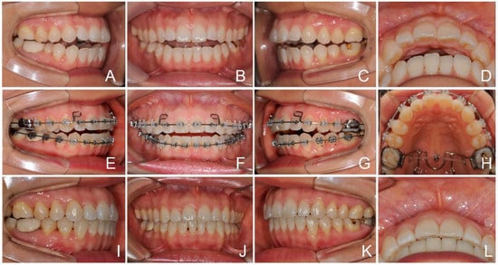
Figure 5.
Case 2. Open-bite correction by the molar intrusion. (A–D) Initial intraoral photos. There was an open bite with minor anterior crowding. Lower second premolars showed lingual tipping. (E–H) After leveling to 0.019 × 0.025 ss, a TAD (1.6 × 6 mm, JA type, RMO, Inc., Denver, CO, USA) was implanted in the mid-palatal area. Accessory hooks were soldered for the second molar intrusion’s power chain traction (H). A power chain was ligated tightly (300 gf for each side). (I–L) After 11 months, the open bite was resolved well.
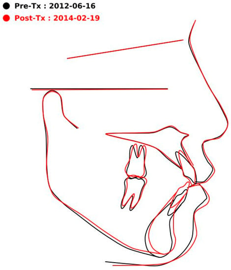
Figure 6.
Case 2. Superimposition showing the following changes: (1) intrusion and distal tipping of the upper molar, (2) slight retroclination and extrusion of the upper incisor, and (3) counterclockwise rotation of the mandible.
3. Anteroposterior Position of a Mid-Palatal TAD
Figure 7A,B show two types of maxillary intrusion. Figure 7A is the “posterior intrusion” type, and the TAD is located posterior to the first molar (Figure 7C,E). The hooks of TPA are also extended distally (Figure 7E). This method has the effect of quickly removing the wedge in the posterior region and distal retraction of the maxillary dentition. This method is indicated in severe open-bite cases without a gummy smile. In most open-bite cases, it has been used effectively.
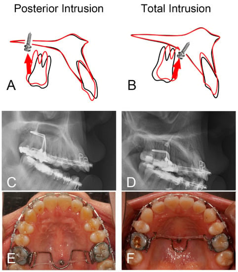
Figure 7.
Posterior intrusion (A,C,E) vs. total intrusion (B,D,F). (A,C,E) In Case 3, to make the posterior intrusion more efficient, the screw and hooks were placed distally. The posterior wedging teeth were intruded more efficiently. (B,D,F) In Case 4, the screw was placed mesial to the first molar. There was an intrusion of total maxillary teeth. When the patient complains of a gummy smile, total intrusion of maxillary teeth is recommended. The drawings in (A,B) were obtained by superimposing the cephalogram after leveling with the post-treatment one; black line: before starting intrusion, red line: after the intrusion.
Figure 7B is the “total intrusion” type, and the TAD is located anterior to the first molar (Figure 7D,F). The hooks of TPA are extended to the mesial (Figure 7F). In this case, both the anterior and the posterior teeth are intruded. This method is recommended in maxillary vertical excess cases with or without an open bite showing a gummy smile.
3.1. Case 3 (Posterior Intrusion, Figure 8 and Figure 9)
Case 3 is a severe open bite and an example of the “posterior intrusion” type. The TAD is located posterior to the first molar (Figure 8I). The hooks of TPA are extended distally. Maxillary third molars were extracted when starting the intrusion. On superimposition (Figure 9), there was posterior intrusion without anterior intrusion. Maxillary teeth were moved distally (Figure 9C). These mechanics are favorable for severe skeletal Class II open-bite cases and can be used to efficiently remove the posterior wedge and close the open bite. The advantage is that an open bite can be solved quickly by the intrusion of the posterior teeth and extrusion of the anterior teeth.
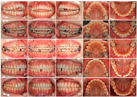
Figure 8.
Case 3. Posterior intrusion. (A–E) Initial intraoral photos showing a narrow upper arch and a wide lower arch. There were three incisors in the mandible. (F–J) After leveling, the posterior intrusion was started. (K–O) Eight months of intrusion. The open bite was decreased. Space for the missing mandibular central incisor was opened up. Overjet was decreased with the proclination of lower incisors and the counterclockwise rotation of the mandible. (P–T) Debonding. (U–Y) Implant and crown restoration of the mandibular right central incisor.
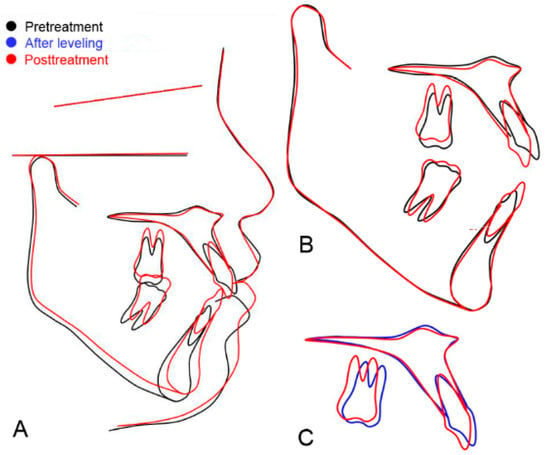
Figure 9.
Case 3. Skeletal and dental changes of “posterior intrusion” case. (A) The superimposition of the initial and posttreatment cephalograms. (B) Maxillary superimposition showing (1) intrusion and distal movement of the upper molar, and (2) extrusion and slight retraction of the upper incisor. Mandibular superimposition showing proclination and extrusion of lower incisors. (C) Superimposition of cephalograms after leveling (blue line) and post treatment (red line). This superimposition excludes the incisor extrusion during the compensating curve’s leveling. The molar was intruded and moved distally. The incisor was extruded and retroclined.
3.2. Case 4 (Total Intrusion, Figure 10 and Figure 11)
Case 4 is an example of the “total intrusion” type. Initial photos showed the compensating curve in the maxilla and the slight reverse curve of Spee in the mandible (Figure 10A–E). The reverse overbite was not as severe as that of Case 3. Maxillary third molars were extracted. After leveling, the open bite decreased following the extrusion of the upper and lower incisors (Figure 10G). The patient had lip incompetency due to excessive anterior vertical height. By placing the TAD anteriorly, anterior teeth were intruded, as well as posterior teeth, which enabled more counterclockwise rotation of the mandible. Without anterior intrusion, the early occluding of anterior teeth would have stopped the mandible’s counterclockwise rotation, resulting in a lower decrease in anterior facial height. Superimposition of cephalograms after leveling (blue line) and after intrusion (orange color line) showing the total intrusion of maxillary teeth (Figure 11C).
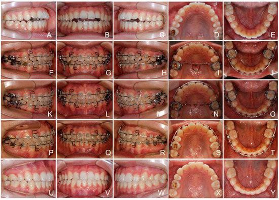
Figure 10.
Case 4. Total intrusion. (A–E) Initial intraoral photos. The compensating curve in the maxilla and the slight reverse curve of Spee in the mandible are visible. The spaces after extraction of upper first and lower second bicuspids were closed by Class I elastics. (F–J) Start of intrusion, after leveling up to 0.019 × 0.025 stainless-steel wire. The extrusion of anterior teeth decreased the open bite. (K–O) Six months after the start of intrusion. Extraction spaces were closed with the Class I elastic bands. (P–T) At the detailing stage. All TADs were removed. (U–Y) After debonding.
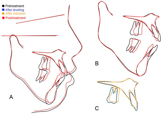
Figure 11.
Case 4. Total intrusion. The superimposition of the initial and posttreatment cephalograms. (A) The superimposition of the initial and posttreatment cephalograms. (B) Maxillary superimposition showing (1) intrusion and mesial movement of the upper molar, and (2) slight intrusion and retraction of upper incisors. Mandibular superimposition showed slight intrusion of lower incisors and molars using lower TADs between first bicuspids and first molars. (C) Superimposition of cephalograms after leveling (blue line) and after intrusion (orange color line). The maxillary molar was intruded and moved mesially, and the incisor was retracted and intruded. This superimposition excluded the extrusion of incisors during the leveling of the compensating curve.
4. Discussion
4.1. Advantages of a Mid-Palatal TAD for the Maxillary Molar Intrusion
The mid-palatal TAD has several advantages over buccal interradicular ones [11,12].
The failure rate of a mid-palatal TAD is very low because the mid-palatal bone is a dense cortical bone, and its thickness is enough to provide stable anchorage throughout the intrusion procedure [14,15,16].
Clinicians can place a TAD in the mid-palatal area without the root trauma. The buccal interradicular spaces between the maxillary first and second molars are frequently too narrow to place a TAD safely. In the authors’ experience, even though buccal TADs were placed well in the buccal interradicular septal bone, they frequently failed as the molars were intruded, with the TADs becoming closer to the alveolar crest and periodontal ligament [15,17,18]. The stability of buccal interradicular TADs is compromised when the implants are close to the alveolar crest and into the periodontal ligament [19,20].
The buccal TADs should be placed in an attached gingiva because, if the TADs are placed in the nonkeratinized movable gingiva, irritation, ulcer, or granulation tissue will happen around it. The TAD position should be high enough to get an intruding force with a long range of action. However, in many cases, the buccal attached gingiva in the maxillary first and second molar area is not wide enough to place TADs high. Conclusively, it is hard to find a good indication for the buccal TADs between the first and second molars.
When it is impossible to use the buccal area between the maxillary first and second molar roots, clinicians usually select the location between the maxillary second premolar and first molar as an alternative site. However, in open-bite cases which need a posterior intrusion, the efficiency is decreased, as the lever arm becomes shorter. In this situation, the mid-palatal TAD is a better choice to get a long lever arm by placing it posteriorly.
A mid-palatal TAD requires only one TAD. Hence, it is more economical.
4.2. Anteroposterior Position of TAD
According to the anteroposterior position of the TAD, the intrusion patterns of maxillary teeth were different, as shown in Cases 3 and 4. This was confirmed in the previous finite element study [21] (Figure 12). When the TAD was placed posterior to the first molars (Figure 12A), molars were intruded and tipped distally (Figure 12C), as shown in Case 3 (Figure 9C) of the “posterior intrusion” type. When the TAD was placed anterior to the first molars (Figure 12B), both molars and incisors were intruded, as shown in Case 4 (Figure 11C) of the “total intrusion” type. Even though the TPA was made of 0.9 mm stainless-steel wire, the power chains’ constricting force produced the molars’ lingual tipping moment. Both models showed the lingual tipping of posterior teeth (Figure 12E,F). The side-effect could be compensated for in these cases by slight expansion (0.5 mm for each side) and crown buccal torque (5°).
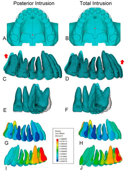
Figure 12.
Two models were constructed according to the position of the mid-palatal TAD. The red dot marks the location of the TAD. (A) Model of “posterior intrusion”. The TAD position is at the interproximal level between the first and second molars. (B) Model of “total intrusion”. The TAD is at the interproximal level between the maxillary second premolar and first molar. (C) Superimposition of the original (white mesh) and deformed model (color) from model of “posterior intrusion”. The red arrow shows that the second molar moved backward and upward. (D) Superimposition of the original (white mesh) and deformed model (color) from model of “total intrusion”. The red arrow shows that the incisor moved upward and forward. (E,F) Both models showed lingual tipping of molars, which could be prevented by expanding the TPA (0.5 mm each side) and applying crown buccal torque (5°). (G,H) Stress on the buccal view. (I,J) Stress on the palatal view. Modified from the figures from Clin J Korean Assoc Orthod 2019;9(2):59–71).
4.3. Total Intrusion of Maxillary Dentition
The intrusion of total maxillary dentition was reported in maxillary vertical excess cases without the open bite by Paik [22]. Sometimes, open-bite cases need this kind of total intrusion even after obtaining the incisal overlap to further decrease the anterior facial height. Case 4 shows an open-bite example in which the total intrusion of the maxillary dentition was required (Figure 13 and Figure 14).
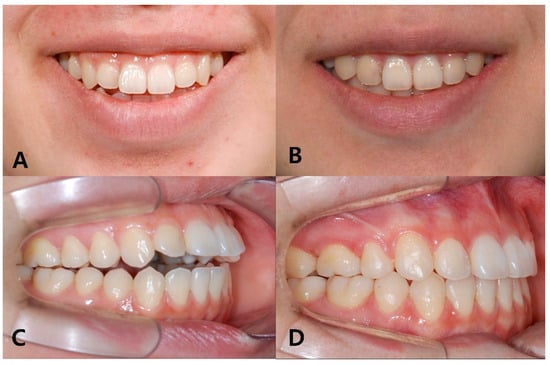
Figure 13.
Case 4. Total intrusion. (A) Initial photo showing a gummy smile. (B) After treatment, the gummy smile was resolved. (C) Initial intraoral photo showing an open bite and compensating curve. (D) Intraoral photo taken after debonding. Maxillary first and mandibular second premolars were extracted.
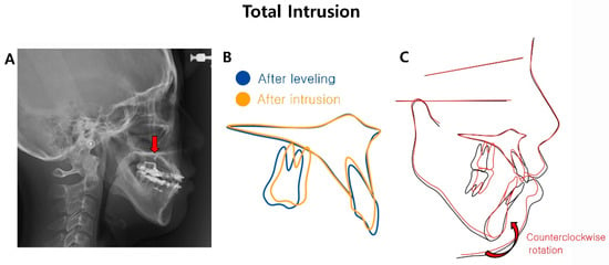
Figure 14.
Case 4. Total intrusion. (A) Cephalogram showing the position of the TAD (red arrow). The mid-palatal TAD (arrow) was placed anterior to the first molar. After leveling and incisor retraction, the upper and lower incisors touched each other, preventing further counterclockwise mandible rotation. (B) Maxillary superimposition after leveling and total intrusion. Total intrusion made the counterclockwise rotation of the mandible possible even after the upper and lower incisors touched after leveling. (C) Superimposition of initial and final tracings. Initial FMA was 43.0° (normal average: 25.2°), showing a steep mandibular plane and long lower anterior facial height. Mandibular counterclockwise rotation decreased the lower facial height.
If the intruding force is designed to pass through the center of resistance [23,24], total maxillary dentition will be intruded. Thus, the TAD was placed mesial to the maxillary first molar, as shown in Figure 7D of Case 4 and Figure 14A of Case 4. Of course, the effect may be somewhat different depending on the characteristics of each patient.
4.4. In What Cases Is Total Intrusion Required?
Case 4 (total intrusion, Figure 10, Figure 11, Figure 13 and Figure 14) shows an example explaining why total intrusion is necessary. This patient wanted to correct her gummy smile (Figure 13A) and open bite (Figure 13C). After treatment, both resolved well (Figure 13B,D).
Before treatment, the intraoral photo showed a maxillary compensating curve (Figure 13C). After leveling, the open bite was resolved due to the extrusion of the maxillary anterior teeth (Figure 14A). However, the problem was that the gummy smile still needed to be treated. Furthermore, it was impossible to decrease the lower anterior facial height using a counterclockwise rotation of the mandible as the upper and lower anterior teeth began to touch. Maxillary posterior intrusion is not a solution in this situation. Total intrusion, including the anterior teeth, was required to resolve the gummy smile and reduce the lower facial height.
A mid-palatal TAD was placed anterior to the maxillary first molar to perform the total intrusion of maxillary dentition (Figure 14A). The TPA hook was directed toward the mesial. Using this mechanic, some intrusion of the maxillary incisors also occurred (Figure 14B), and a counterclockwise rotation of the mandible was possible (Figure 14C).
The effects of the anteroposterior positioning of the mid-palatal TAD can be different depending on the characteristics of each patient and the tooth extraction. Systematic and objective studies, including many samples, are required in the future.
4.5. Notes on the Mechanics
- (1)
- Devices on the roof of the mouth (TAD, TPA, power chain, and lingual buttons) can be uncomfortable on the tongue. Among them, the protruding parts of TPA and hooks must be well finished so as not to cause irritation.
- (2)
- If the roof of the mouth is low, the effect is reduced because the horizontal constricting force is increased more than the vertical intruding force.
- (3)
- The force load for a maxillary posterior segment was 300 gf [25,26]. The force was reactivated by changing the power chain every four weeks. However, there was quite a wide range of forces in previous reports. For a single molar intrusion, the intruding force ranged from 50 to 250 gf [13,27]. For a maxillary segmental intrusion, the force ranged from 300 to 400 gf [2,9,25,26]. According to Ersahan and Sabuncuoglu’s study using the laser Doppler flowmetry on pulpal blood flow in maxillary molars, the light force of 125 gf for one single molar intrusion was recommended for pulp vitality [13].
4.6. What Is the Future of Open-Bite Treatment and Research?
Recently, clear aligners, which are excellent aesthetically compared to brackets and archwires, have been actively studied and tried in various cases. Research results on clear aligners’ effect on the open bite or vertical control are still controversial [28,29,30]. Nevertheless, attempts to treat the open bite with clear aligners, especially by applying TAD, have attracted great attention [31,32,33]. The posterior bite block effect [34] of clear aligners and posterior intrusion using TAD may produce a synergic effect. In particular, considering the stability and safety of mid-palatal TADs, if clear aligners can be used with a mid-palatal TAD, it would be a good open-bite treatment option. In order to treat the open bite by combining clear aligners and TAD, further efforts to develop mechanics are required in the future.
In extraction cases, the effect of TAD location will differ from that in non-extraction cases. If additional studies using FEM and clinical studies are conducted in extraction cases, open-bite treatment will become more sophisticated and predictable. In addition, if clear aligners are to be actively used for open-bite treatment in the future, research using FEM will help to clarify the mechanism and predict side-effects [35].
5. Conclusions
The open-bite cases treated with a mid-palatal TAD and an intrusion TPA were presented. The mechanics were explained with the advantages. The intrusion patterns differed according to the anteroposterior position of mid-palatal TADs. When the TAD was placed distal to the first molar, the posterior intrusion was obtained by removing the posterior wedge efficiently. If the TAD was placed mesial to the first molar, the total intrusion of maxillary dentition was obtained.
Author Contributions
Conceptualization, T.W. and T.-W.K.; writing—original draft, T.-W.K.; writing—review and editing, T.W.; supervision, T.W. All authors have read and agreed to the published version of the manuscript.
Funding
This research received no external funding.
Institutional Review Board Statement
Not applicable.
Informed Consent Statement
Not applicable.
Data Availability Statement
Not applicable.
Conflicts of Interest
The authors declare no conflict of interest.
References
- Sugawara, J.; Baik, U.B.; Umemori, M.; Takahashi, I.; Nagasaka, H.; Kawamura, H.; Mitani, H. Treatment and posttreatment dentoalveolar changes following intrusion of mandibular molars with application of a skeletal anchorage system (SAS) for open bite correction. Int. J. Adult Orthodon. Orthognath. Surg. 2002, 17, 243–253. [Google Scholar] [PubMed]
- Erverdi, N.; Keles, A.; Nanda, R. The use of skeletal anchorage in open bite treatment: A cephalometric evaluation. Angle Orthod. 2004, 74, 381–390. [Google Scholar] [PubMed]
- Kuroda, S.; Katayama, A.; Takano-Yamamoto, T. Severe anterior open-bite case treated using titanium screw anchorage. Angle Orthod. 2004, 74, 558–567. [Google Scholar] [PubMed]
- Park, H.S.; Kwon, T.G.; Kwon, O.W. Treatment of open bite with microscrew implant anchorage. Am. J. Orthod. Dentofac. Orthop. 2004, 126, 627–636. [Google Scholar] [CrossRef] [PubMed]
- Miller, J.R. Treatment of a twice-relapsed anterior open bite using temporary anchorage devices, myofunctional therapy, and fixed passive self-ligating appliances. Am. J. Orthod. Dentofac. Orthop. 2020, 157, 832–842. [Google Scholar] [CrossRef] [PubMed]
- Park, H.S.; Kwon, O.W.; Sung, J.H. Nonextraction treatment of an open bite with microscrew implant anchorage. Am. J. Orthod. Dentofac. Orthop. 2006, 130, 391–402. [Google Scholar] [CrossRef] [PubMed]
- Erverdi, N.; Usumez, S.; Solak, A. New generation open-bite treatment with zygomatic anchorage. Angle Orthod. 2006, 76, 519–526. [Google Scholar]
- Cornelis, M.A.; Scheffler, N.R.; Mahy, P.; Siciliano, S.; De Clerck, H.J.; Tulloch, J.F. Modified miniplates for temporary skeletal anchorage in orthodontics: Placement and removal surgeries. J. Oral Maxillofac. Surg. 2008, 66, 1439–1445. [Google Scholar] [CrossRef]
- Akan, S.; Kocadereli, I.; Aktas, A.; Tasar, F. Effects of maxillary molar intrusion with zygomatic anchorage on the stomatognathic system in anterior open bite patients. Europ. J. Orthod. 2013, 35, 93–102. [Google Scholar] [CrossRef]
- Paik, C.H.; Woo, Y.J.; Boyd, R.L. Treatment of an adult patient with vertical maxillary excess using miniscrew fixation. J. Clin. Orthod. 2003, 37, 423–428. [Google Scholar]
- Paik, C.H.; Park, I.K.; Woo, Y.J.; Kim, T.W. Orthodontic Miniscrew Implants; Clinical Applications, 1st ed.; Mosby Elsevier: St. Louis, MO, USA, 2009; pp. 144–146. [Google Scholar]
- Kim, T.W.; Kim, H.Y. Clinical Application of Orthodontic Mini-Implant, 2nd ed.; Myung Moon: Seoul, Republic of Korea, 2008; pp. 168–211. [Google Scholar]
- Ersahan, S.; Sabuncuoglu, F.A. Effects of magnitude of intrusive force on pulpal blood flow in maxillary molars. Am. J. Orthod. Dentofac. Orthop. 2015, 148, 83–89. [Google Scholar] [CrossRef] [PubMed]
- Leo, M.; Cerroni, L.; Pasquantonio, G.; Condò, S.G.; Condò, R. Temporary anchorage devices (TADs) in orthodontics: Review of the factors that influence the clinical success rate of the mini-implants. Clin. Ter. 2016, 167, e70–e77. [Google Scholar] [CrossRef] [PubMed]
- Gurdan, Z.; Szalma, J. Evaluation of the success and complication rates of self-drilling orthodontic mini-implants. Niger J. Clin. Pract. 2018, 21, 546–552. [Google Scholar] [CrossRef] [PubMed]
- Yu, W.P.; Tsai, M.T.; Yu, J.H.; Huang, H.L.; Hsu, J.T. Bone quality affects stability of orthodontic miniscrews. Sci. Rep. 2022, 12, 2849. [Google Scholar] [CrossRef]
- Franzotti, S.E.; da Cunha, A.C.; Paludo, B.D.; Franzotti, S.C. Camouflage of a high-angle skeletal Class II open-bite malocclusion in an adult after mini-implant failure during treatment. Am. J. Orthod. Dentofac. Orthop. 2017, 151, 583–597. [Google Scholar] [CrossRef]
- Kuroda, S.; Sugawara, Y.; Deguchi, T.; Kyung, H.M.; Takano-Yamamoto, T. Clinical use of miniscrew implants as orthodontic anchorage: Success rates and postoperative discomfort. Am. J. Orthod. Dentofac. Orthop. 2007, 131, 9–15. [Google Scholar] [CrossRef]
- Kuroda, S.; Yamada, K.; Deguchi, T.; Hashimoto, T.; Kyung, H.M.; Takano-Yamamoto, T. Root proximity is a major factor for screw failure in orthodontic anchorage. Am. J. Orthod. Dentofac. Orthop. 2007, 131 (Suppl. S4), S68–S73. [Google Scholar] [CrossRef]
- Min, K.I.; Kim, S.C.; Kang, K.H.; Cho, J.H.; Lee, E.H.; Chang, N.Y.; Chae, J.M. Root proximity and cortical bone thickness effects on the success rate of orthodontic micro-implants using cone beam computed tomography. Angle Orthod. 2012, 82, 1014–1021. [Google Scholar] [CrossRef]
- Choi, K.H.; Yang, I.H.; Baek, S.H.; Ahn, S.J.; Lim, W.H.; Lee, S.J.; Kim, T.W. Effect of Anteroposterior Position of the Mid-palatal TAD on the Intrusion of Maxillary Posterior Teeth: A Three-Dimensional Finite Element Analysis. Clin. J. Korean Assoc. Orthod. 2019, 9, 59–71. Available online: https://www.kao.or.kr/file/journals/9-2-1.pdf (accessed on 23 April 2023). [CrossRef]
- Paik, C.H.; Park, H.S.; Ahn, H.W. Treatment of vertical maxillary excess without open bite in a skeletal Class II hyperdivergent patient. Angle Orthod. 2017, 87, 625–633. [Google Scholar] [CrossRef]
- Jeong, G.M.; Sung, S.J.; Lee, K.J.; Chun, Y.S.; Mo, S.S. Finite-element investigation of the center of resistance of the maxillary dentition. Korean J. Orthod. 2009, 39, 83–94. [Google Scholar] [CrossRef]
- Kojima, Y.; Fukui, H. A finite element simulation of initial movement, orthodontic movement, and the centre of resistance of the maxillary teeth connected with an archwire. Europ. J. Orthod. 2014, 36, 255–261. [Google Scholar] [CrossRef] [PubMed]
- Kato, S.; Kato, M. Intrusion of molars with implants as anchorage: A report of two cases. Clin. Implant. Dent. Relat. Res. 2006, 8, 100–106. [Google Scholar] [CrossRef] [PubMed]
- Kučera, J.; Marek, I.; Tomeček, M.; Foltán, R.; Foltánová, B. Intrusion of overerupted molars with temporary anchorage devices before prosthetic reconstruction: A case report. Clin. Case Rep. 2022, 10, e6108. [Google Scholar] [CrossRef] [PubMed]
- Melsen, B.; Fiorelli, G. Upper molar intrusion. J. Clin. Orthod. 1996, 30, 91–96. [Google Scholar] [PubMed]
- Khosravi, R.; Cohanim, B.; Hujoel, P.; Daher, S.; Neal, M.; Liu, W.; Huang, G. Management of overbite with the Invisalign appliance. Am. J. Orthod. Dentofac. Orthop. 2017, 151, 691–699.e2. [Google Scholar] [CrossRef]
- Rask, H.; English, J.D.; Colville, C.; Kasper, F.K.; Gallerano, R.; Jacob, H.B. Cephalometric evaluation of changes in vertical dimension and molar position in adult non-extraction treatment with clear aligners and traditional fixed appliances. Dental Press J. Orthod. 2021, 26, e2119360. [Google Scholar] [CrossRef]
- Steele, B.P.; Pandis, N.; Darendeliler, M.A.; Papadopoulou, A.K. A comparative assessment of the dentoskeletal effects of clear aligners vs miniplate-supported posterior intrusion with fixed appliances in adult patients with anterior open bite. A multicenter, retrospective cohort study. Am. J. Orthod. Dentofac. Orthop. 2022, 162, 214–228.e4. [Google Scholar] [CrossRef]
- Pinho, T.; Santos, M. Skeletal open bite treated with clear aligners and miniscrews. Am. J. Orthod. Dentofac. Orthop. 2021, 159, 224–233. [Google Scholar] [CrossRef] [PubMed]
- Waxler, R. Correcting skeletal open bite with clear aligners and miniscrews; Comment. Am. J. Orthod. Dentofac. Orthop. 2021, 160, 165. [Google Scholar] [CrossRef]
- Agarwal, Y.; Goyal, M.; Kumar, M.; Kaur, A.; Jharkhand; Pradesh, U. Skeletal open bite treated with clear aligners and miniscrews; Comment. Am. J. Orthod. Dentofac. Orthop. 2021, 160, 166–167. [Google Scholar] [CrossRef] [PubMed]
- Harris, K.; Ojima, K.; Dan, C.; Upadhyay, M.; Alshehri, A.; Kuo, C.-L.; Mu, J.; Uribe, F.; Nanda, R. Evaluation of open bite closure using clear aligners: A retrospective study. Prog. Orthod. 2020, 21, 23. [Google Scholar] [CrossRef] [PubMed]
- Zhu, G.-Y.; Zhang, B.; Yao, K.; Lu, W.-X.; Peng, J.-J.; Shen, Y.; Zhao, Z.-H. Finite element analysis of the biomechanical effect of clear aligners in extraction space closure under different anchorage controls. Am. J. Orthod. Dentofac. Orthop. 2023, in press. [Google Scholar] [CrossRef] [PubMed]
Disclaimer/Publisher’s Note: The statements, opinions and data contained in all publications are solely those of the individual author(s) and contributor(s) and not of MDPI and/or the editor(s). MDPI and/or the editor(s) disclaim responsibility for any injury to people or property resulting from any ideas, methods, instructions or products referred to in the content. |
© 2023 by the authors. Licensee MDPI, Basel, Switzerland. This article is an open access article distributed under the terms and conditions of the Creative Commons Attribution (CC BY) license (https://creativecommons.org/licenses/by/4.0/).