
Experimental Investigation on the Granite Erosion Characteristics of a Variable Cross-Section Squeezed Pulsed Water Jet

Abstract
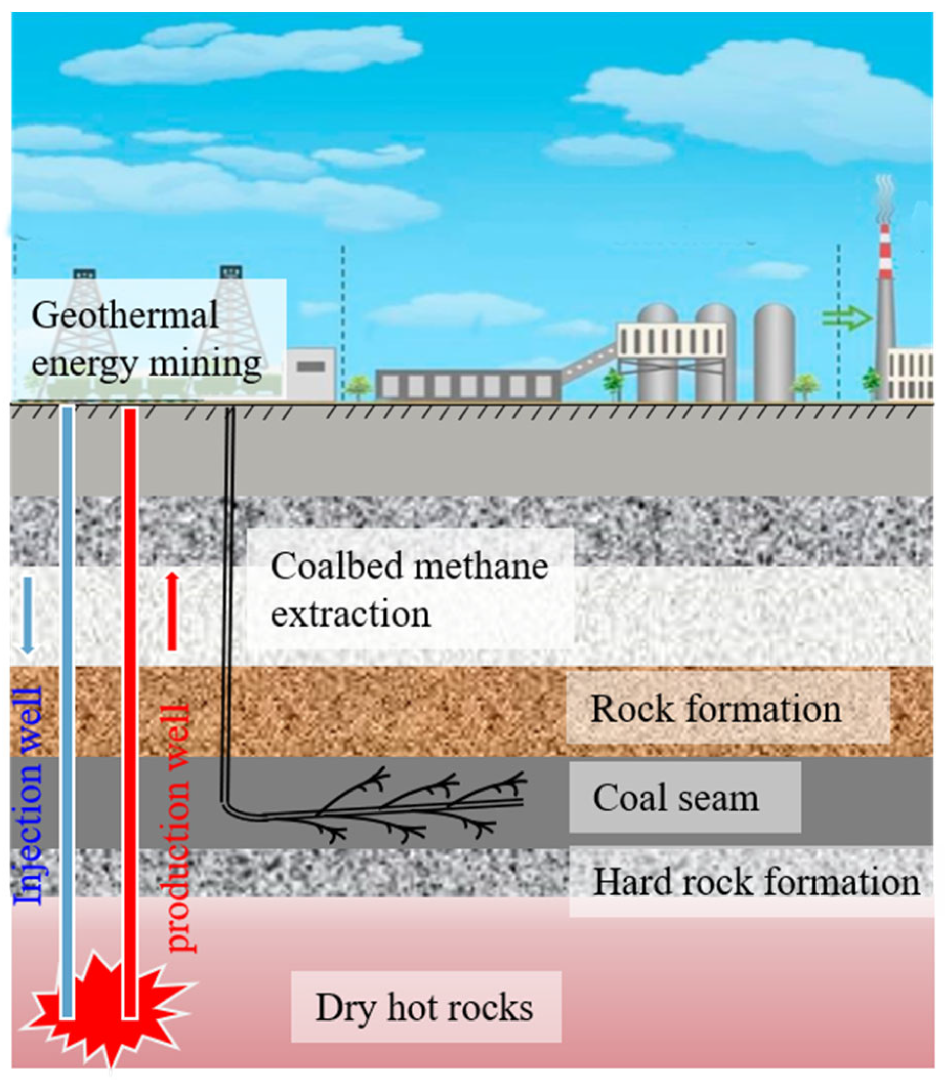
:1. Introduction
2. Theoretical Background
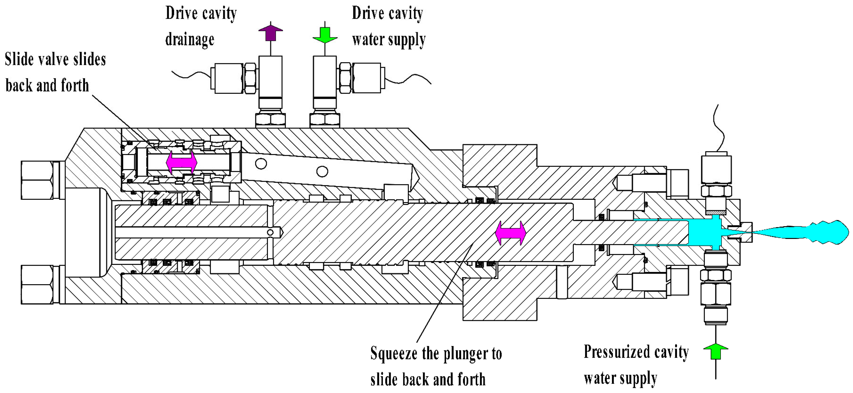
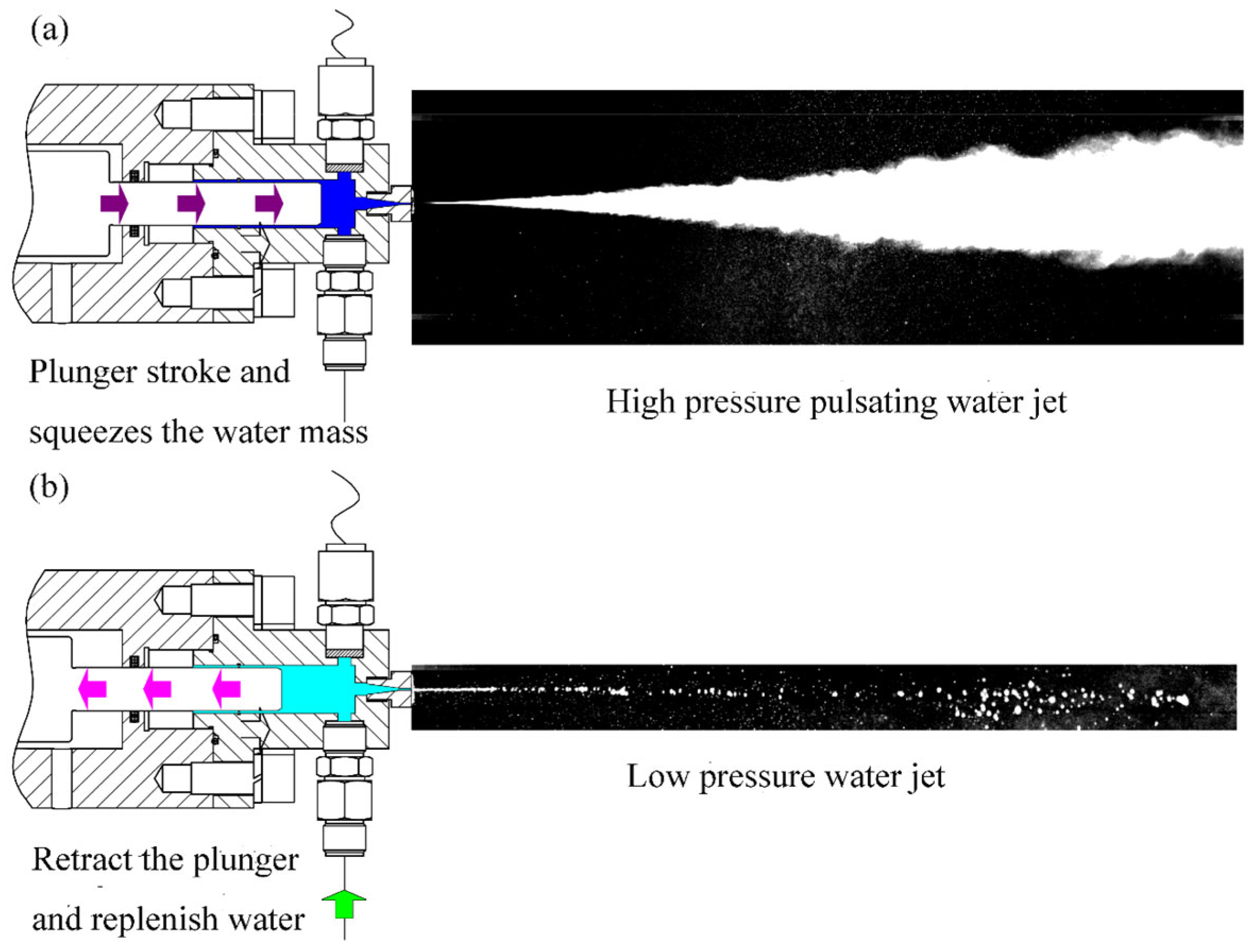
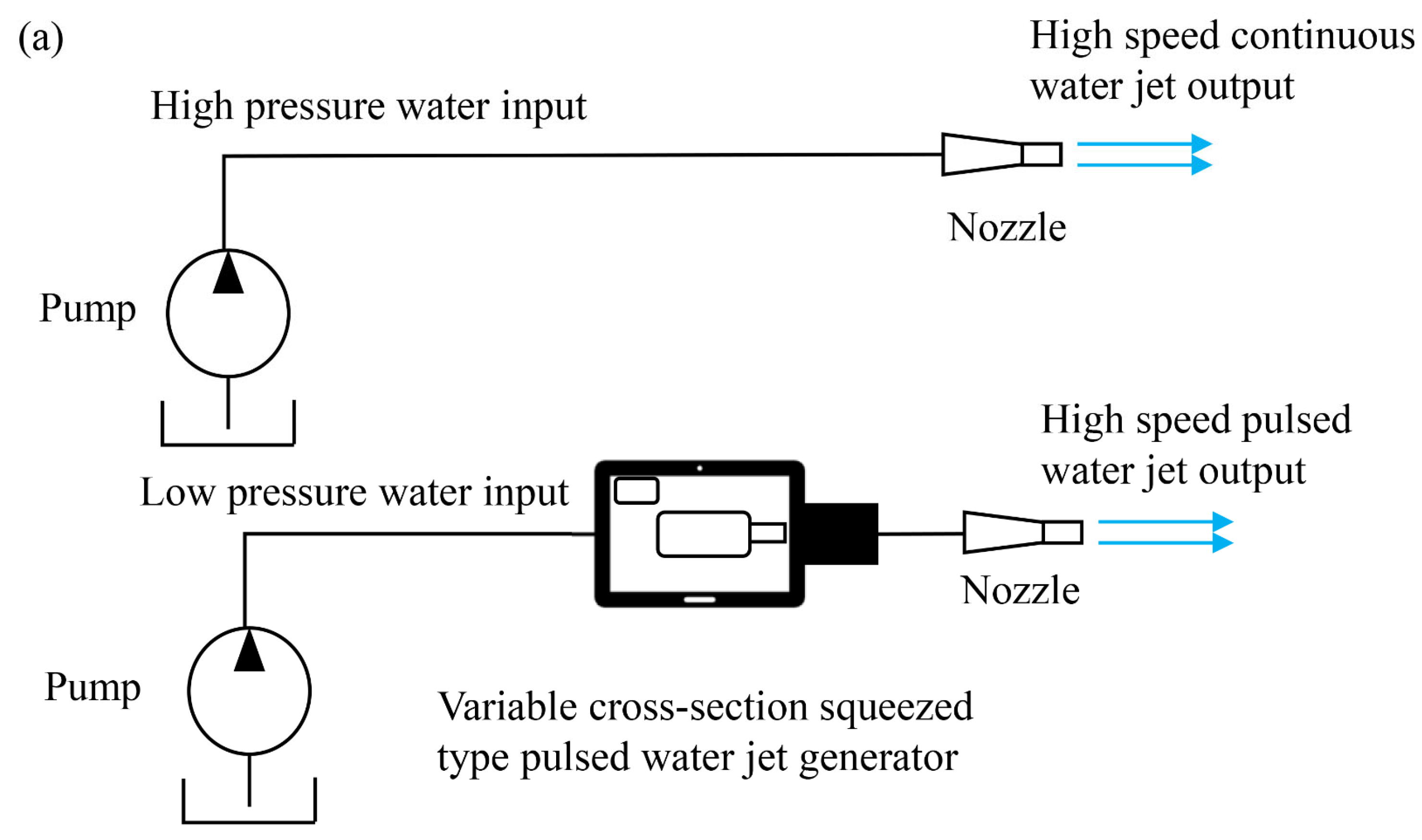
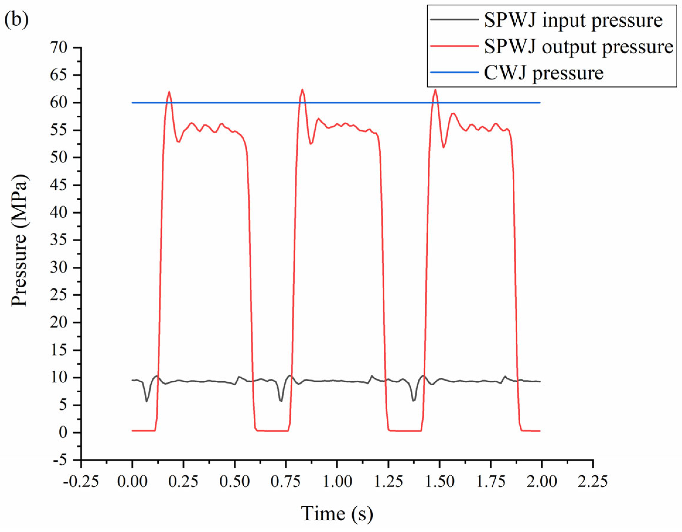
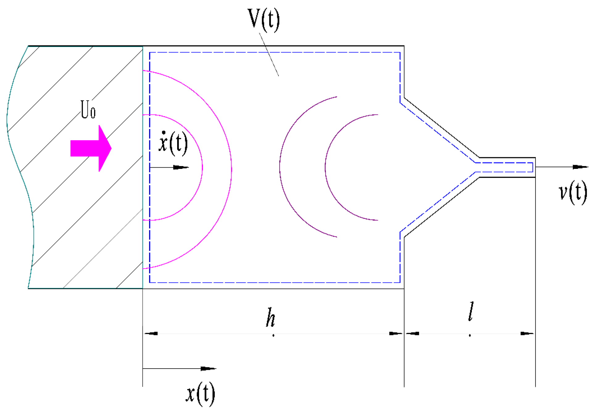
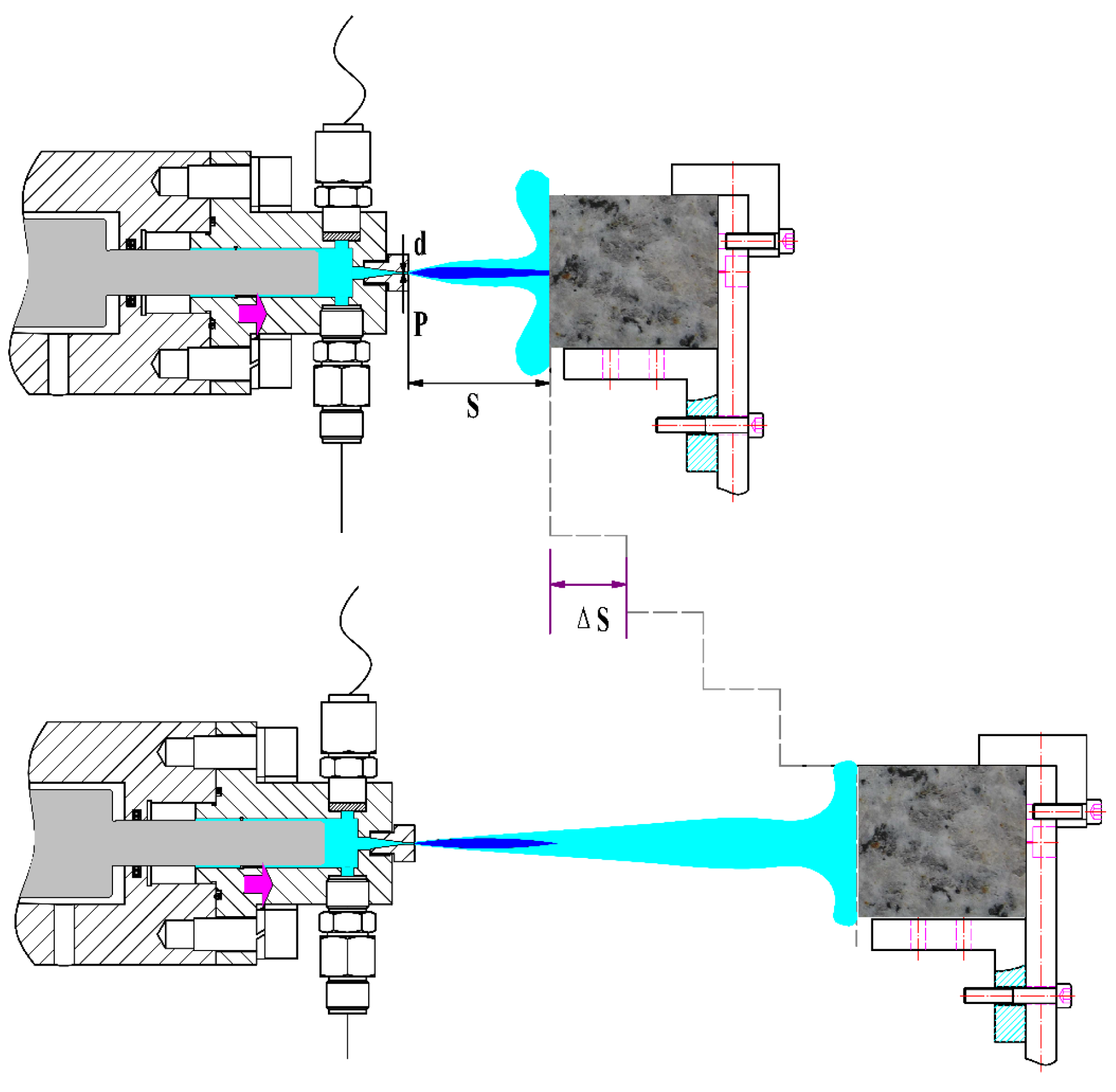
2.1. Working Principles of SPWJ
2.2. Impingement Characteristics of Pulsed Jets on a Rock Surface
3. Experimental Facilities and Procedures
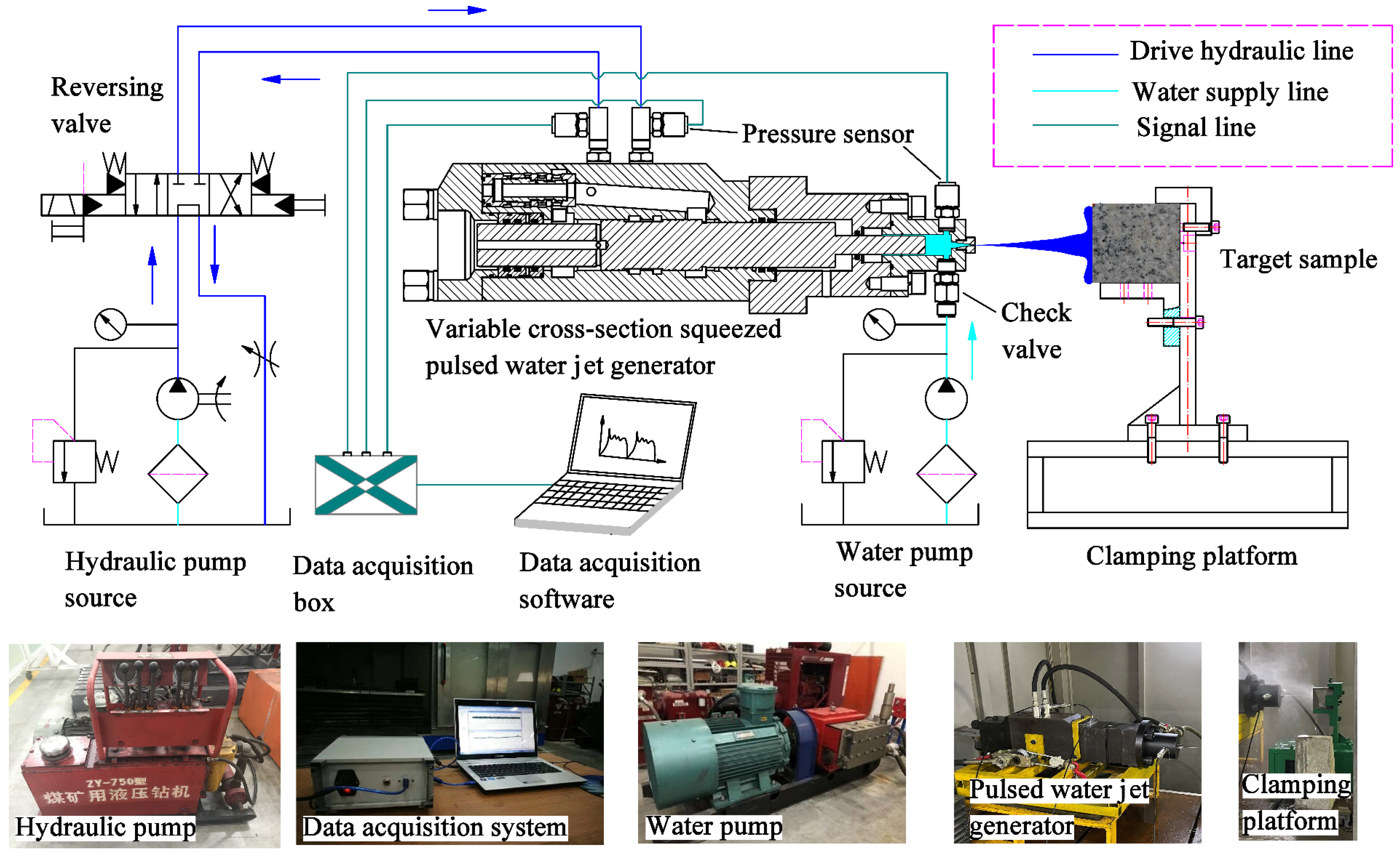
3.1. Facilities
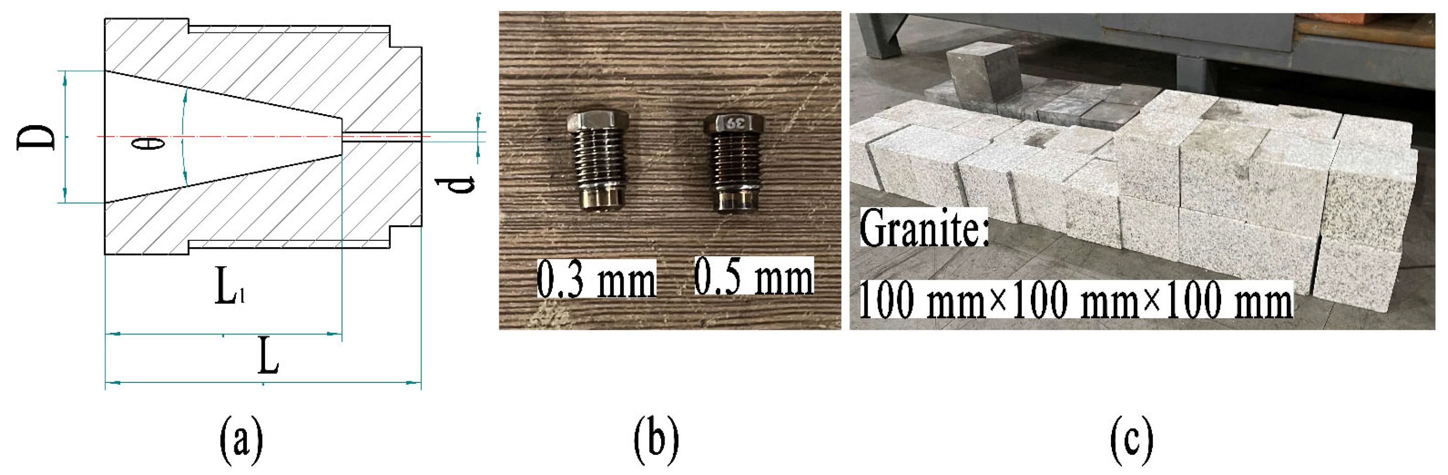
3.2. Nozzle and Materials
3.3. Experimental Procedures
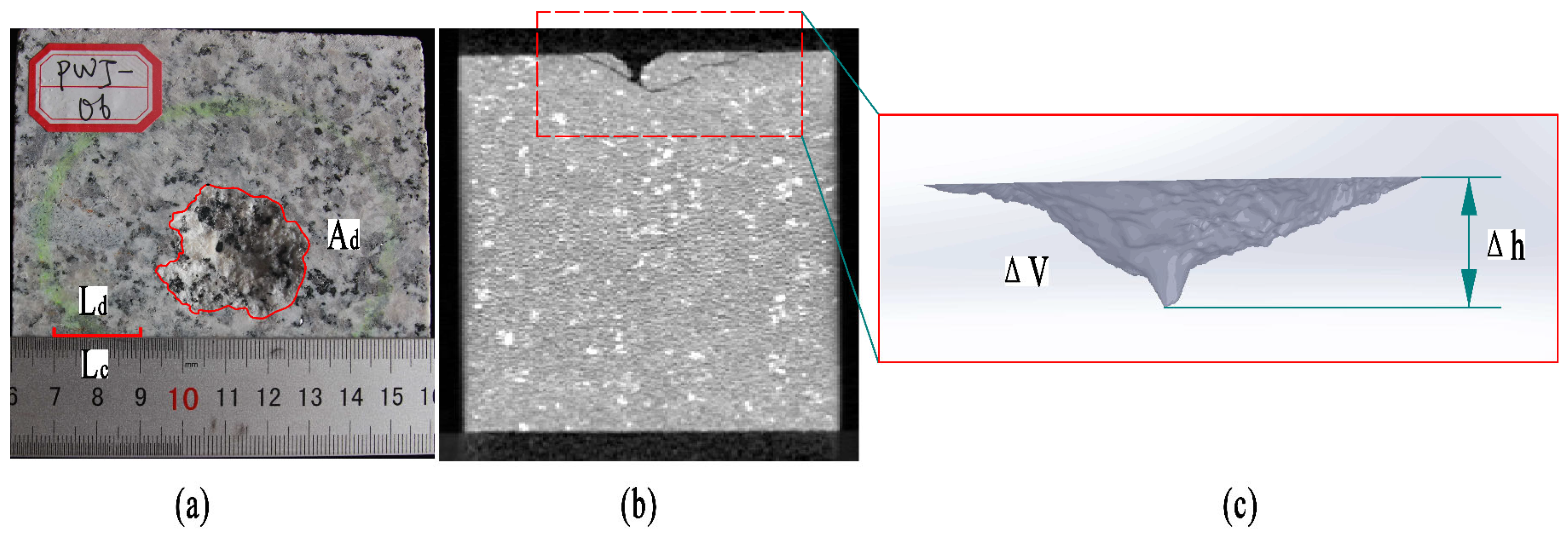
3.4. Evaluation Methods
3.5. Experimental Uncertainty
4. Results and Discussions
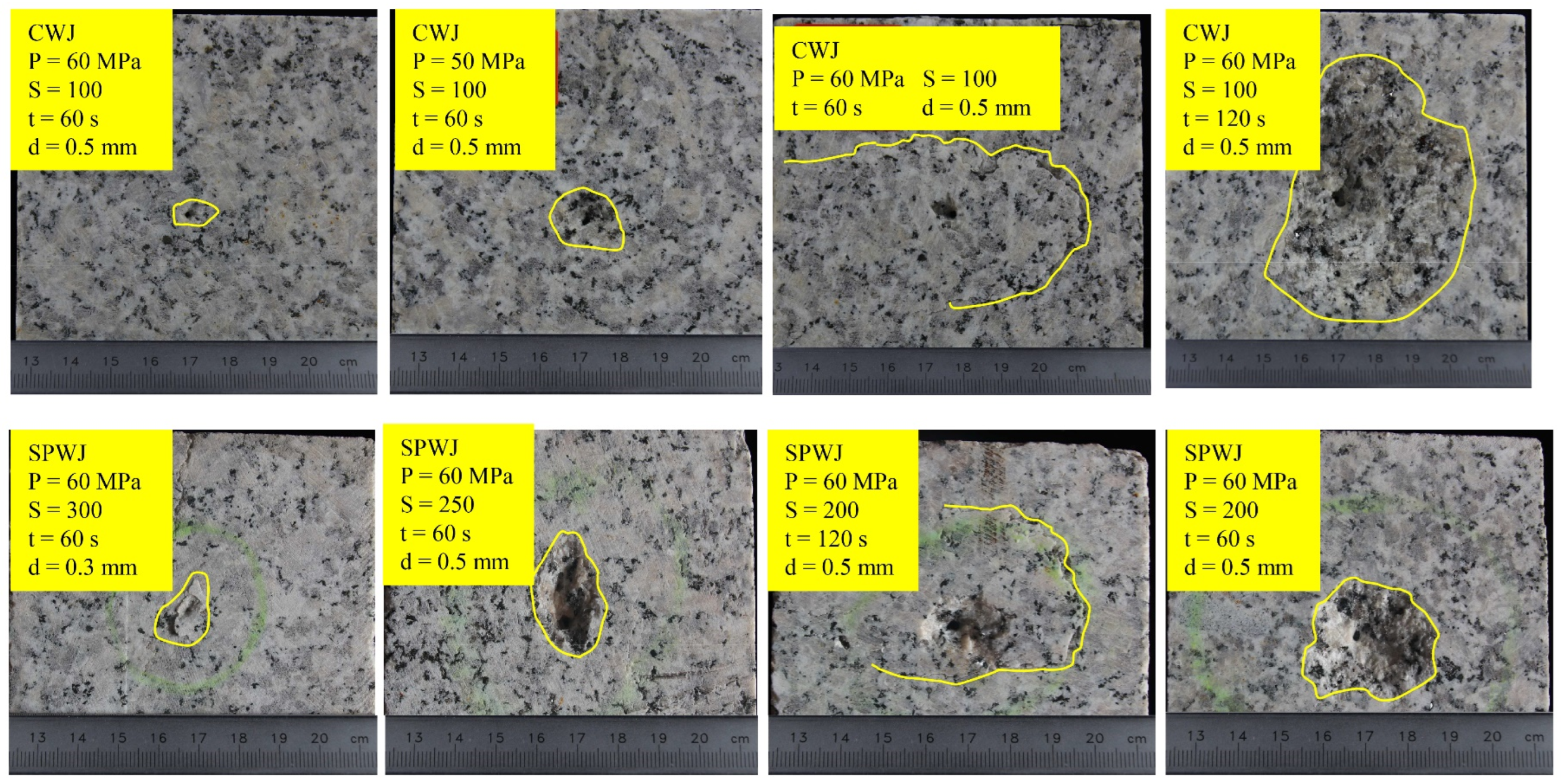
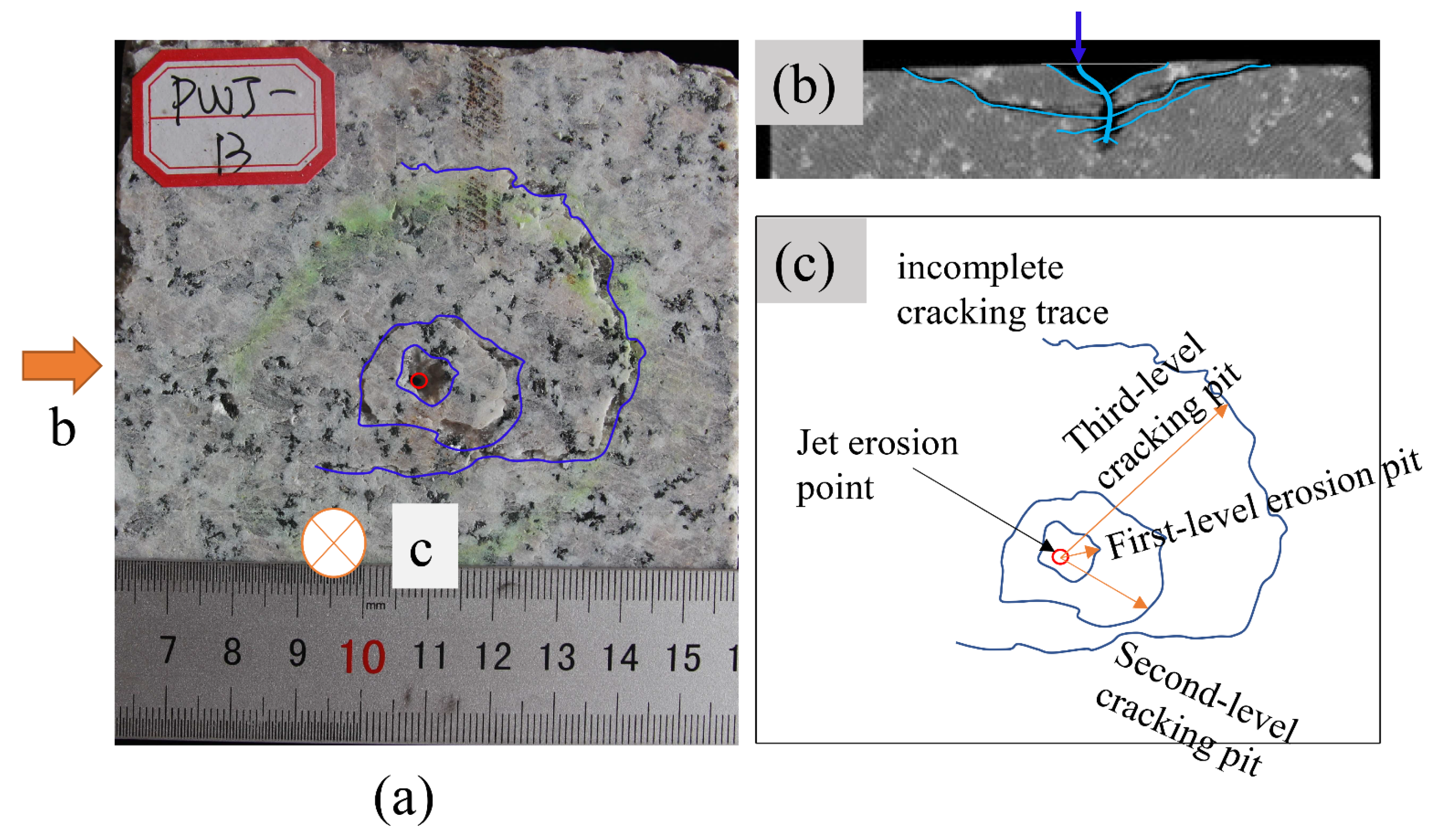
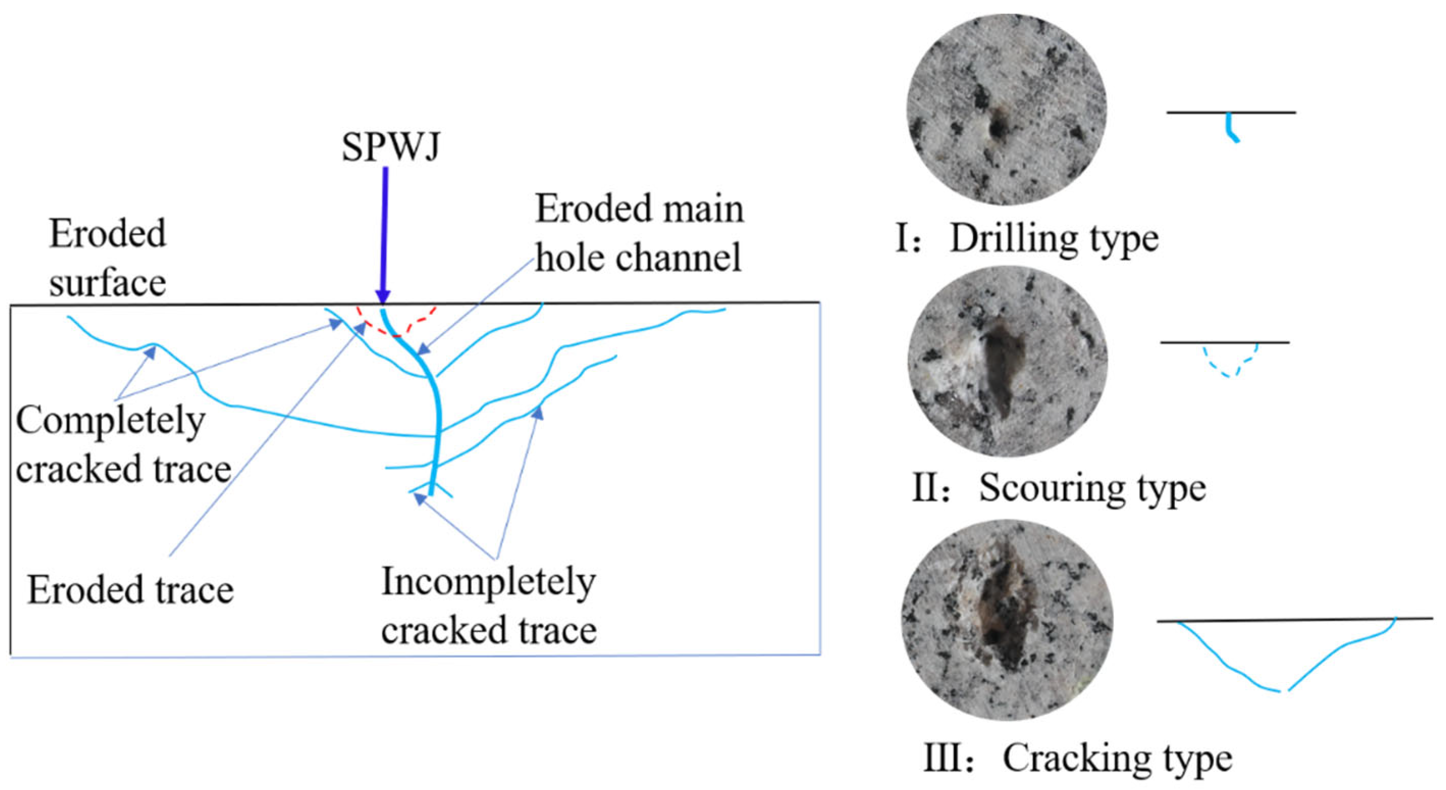
4.1. SPWJ Erosion Granite Failure Mode
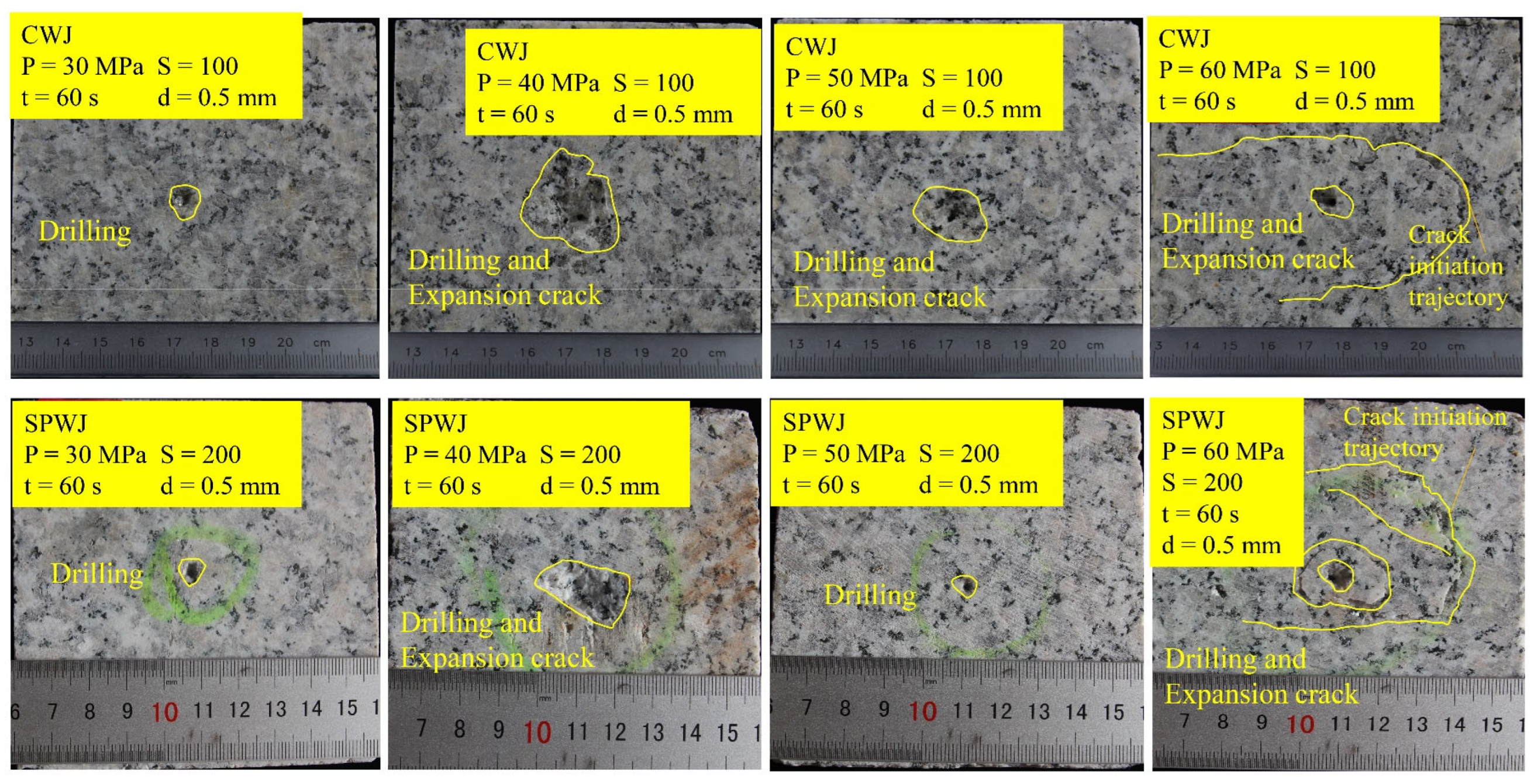
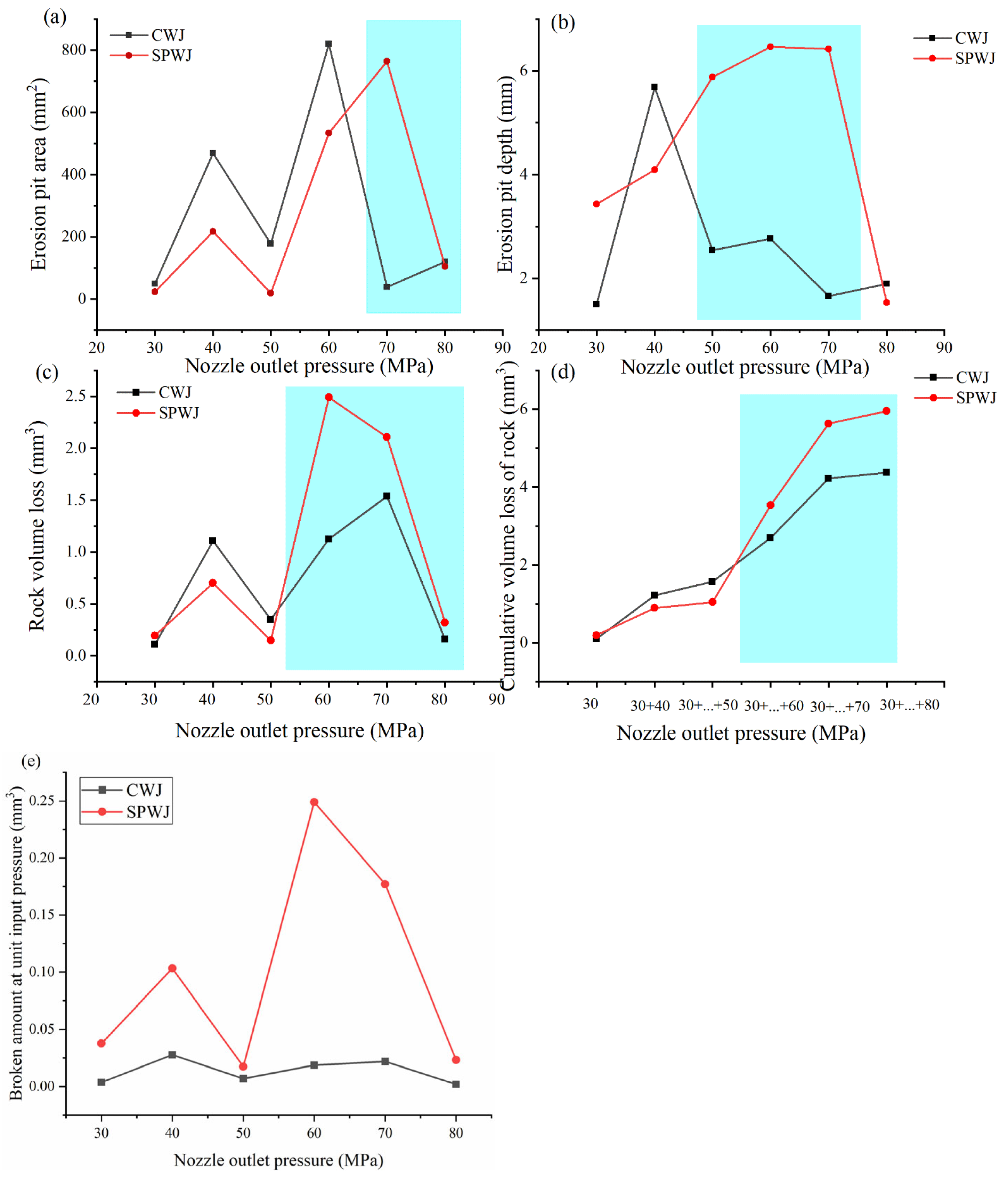
4.2. Influence of Nozzle Outlet Pressure on Rock Breaking Effect
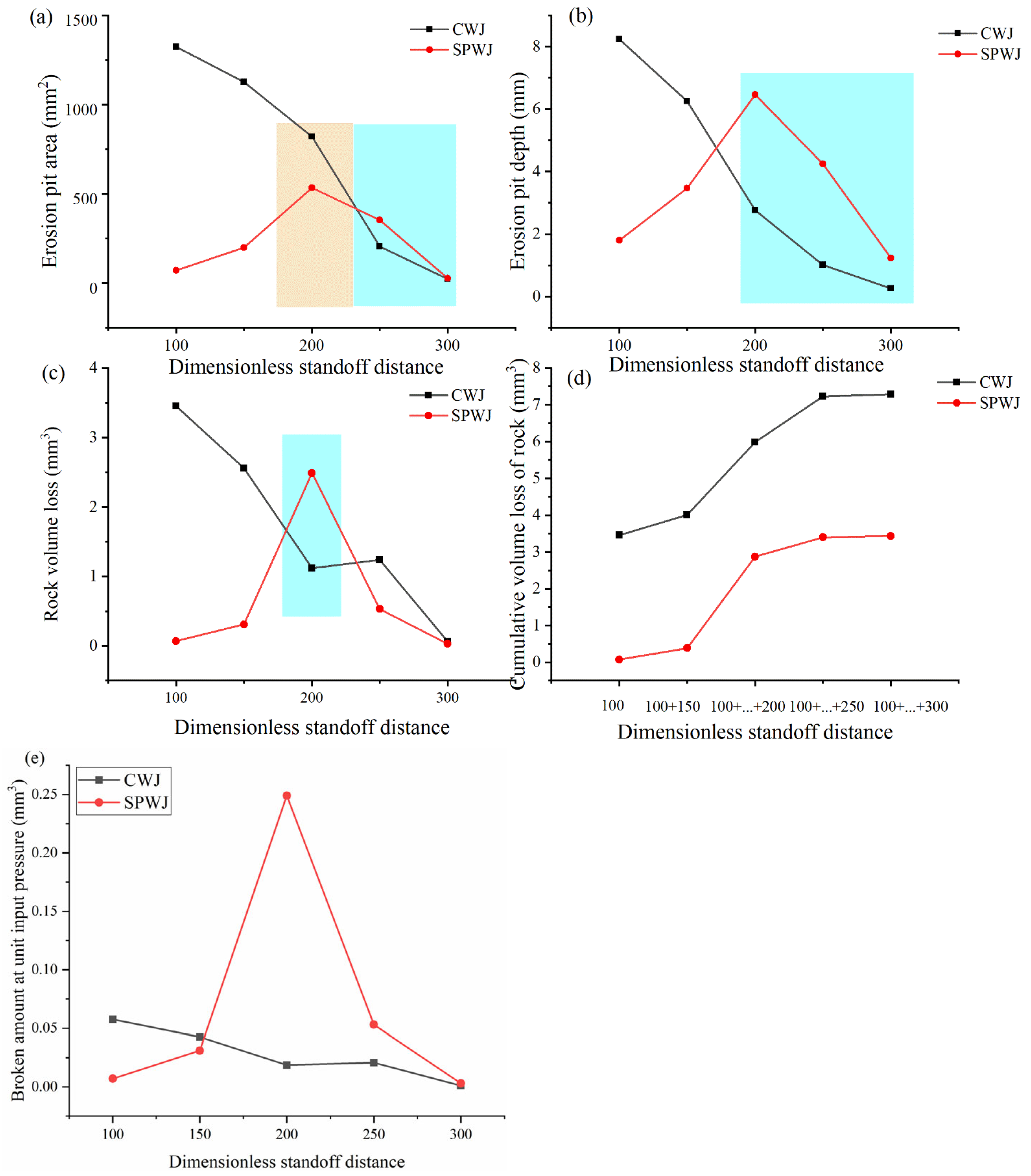
4.3. Influence of the Dimensionless Standoff Distance on the Rock-Breaking Effect
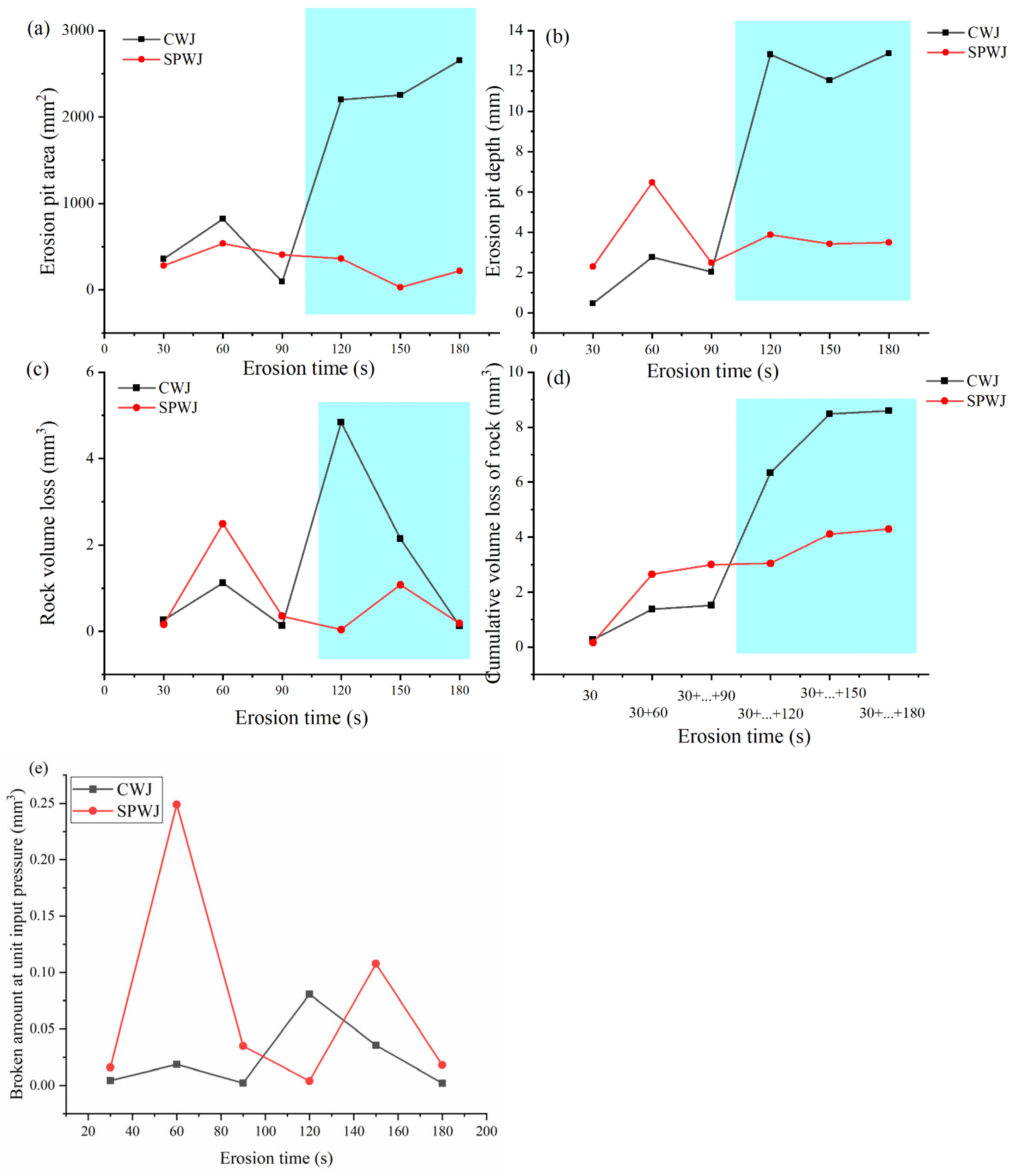
4.4. Influence of Erosion Time on Rock Breaking Effect
5. Conclusions
- (1)
- During the process of SPWJ erosion of hard rock, the water hammer stress waveforms tensile cracks inside the rock, and the jet enters the cracks to further water wedge and crack the granite, forming preliminary erosion pits. As the jet erosion target distance increases, the jet energy decays to the point where cracks cannot be formed, and the rock fragmentation reaches the limit position.
- (2)
- With an increase in pressure, the rock-breaking capacity of SPWJ initially increases and then decreases, reaching its maximum at 60 MPa. Under the experimental conditions, the erosion ability of CWJ is better than that of SPWJ when the pressure is lower than 60 MPa, and the erosion ability of SPWJ is better than that of CWJ when the pressure is above 60 MPa.
- (3)
- The optimal dimensionless standoff distance for the SPWJ is approximately twice that of the CWJ. Under the experimental conditions, the optimal dimensionless target distance for the CWJ is 100, while for the SPWJ, it is 200. Moreover, the SPWJ is more sensitive to the target distance than the CWJ. When the SPWJ is offset from the experimental optimal standoff distance of S = 200 by either 50 to 150 or 250, the jet erosion volume is reduced by 87.5% and 78.7%, respectively. In comparison, for CWJ, this reduction in jet erosion volume is only 25.8%.
- (4)
- SPWJ’s feedback on the erosion time is relatively rapid, and the peak value of crushing can be reached at the beginning of the erosion. With the extension of the erosion time, the effective crushing amount of the squeeze pulse water jet hardly increases. When the erosion time is less than the 90 s, the crushing ability of SPWJ is better than CWJ.
- (5)
- Under the condition of unit input pressure, the overall erosion ability of SPWJ on granite is better than that of CWJ. The mechanism of SPWJ erosion and decomposition of granite needs to be analyzed theoretically and experimentally.
Author Contributions
Funding
Institutional Review Board Statement
Informed Consent Statement
Data Availability Statement
Acknowledgments
Conflicts of Interest
References
- Xu, F.; Ma, T.; Tang, Y.; Song, X.; Shi, Y. Evaluation of heat extraction performance for vertical multi-fractures in enhanced geothermal system. Energy Sources Part A Recover. Util. Environ. Eff. 2021, 1–21. [Google Scholar] [CrossRef]
- Lu, Y.; Huang, F.; Liu, X.; Ao, X. On the failure pattern of sandstone impacted by high-velocity water jet. Int. J. Impact Eng. 2015, 76, 67–74. [Google Scholar] [CrossRef]
- Ge, Z.; Shangguan, J.; Zhou, Z.; Li, Z.; Liu, L.; Chen, C.; Shao, C. Investigation of Fracture Damage and Breaking Energy Consumption of Hard Rock Repeatedly Cut by Abrasive Water Jet. Rock Mech. Rock Eng. 2023, 56, 3215–3230. [Google Scholar] [CrossRef]
- Grosso, B.; Dentoni, V.; Bortolussi, A. Effect of the Rock Stress on the Water Jet Cutting Performance. Rock Mech. Rock Eng. 2021, 54, 4987–4999. [Google Scholar] [CrossRef]
- Li, H.; Huang, Z.; Li, J.; Li, X.; Jiang, T.; Chen, J. Rock breaking characteristics by swirling impeller abrasive water jet (SAWJ) on granite. Int. J. Rock Mech. Min. Sci. 2022, 159, 105230. [Google Scholar] [CrossRef]
- Liu, Z.; Ma, Z.; Liu, K.; Zhao, S.; Wang, Y. Coupled CEL-FDEM modeling of rock failure induced by high-pressure water jet. Eng. Fract. Mech. 2023, 277, 108958. [Google Scholar] [CrossRef]
- Pan, Y.; Zhai, S.; Meng, X.; Pei, K.; Huo, F. Study on the Fracturing of Rock by High-Speed Water Jet Impact. Processes 2022, 11, 114. [Google Scholar] [CrossRef]
- Liu, Y.; Gao, D.; Wei, Z.; Balachandran, B.; Wang, Z.; Tan, L. A new solution to enhance cuttings transport in mining drilling by using pulse jet mill technique. Sci. China Technol. Sci. 2018, 62, 875–884. [Google Scholar] [CrossRef]
- Song, X.; Xu, F.; Shi, Y.; Zhang, Y.; Pan, Z.; Song, G. Numerical simulation of the rotating water jet flushing the insoluble particles in the salt cavern underground gas storage. J. Energy Storage 2020, 33, 101869. [Google Scholar] [CrossRef]
- Dos Santos, R.P.; Guimarães, J.M.F.; Faria, P.D.O.; Noronha, M.A.M. Water jet tunneling: A theoretical advanced rate evaluation. REM—Int. Eng. J. 2018, 71, 159–166. [Google Scholar] [CrossRef]
- Liu, S.; Ji, H.; Han, D.; Guo, C. Experimental investigation and application on the cutting performance of cutting head for rock cutting assisted with multi-water jets. Int. J. Adv. Manuf. Technol. 2017, 94, 2715–2728. [Google Scholar] [CrossRef]
- Xue, Y.; Si, H.; Hu, Q. The propagation of stress waves in rock impacted by a pulsed water jet. Powder Technol. 2017, 320, 179–190. [Google Scholar] [CrossRef]
- Hu, M.; Li, B.; Zhang, B.; Zhang, C.; Nie, L.; Liu, Z.; Cao, W. Effect of Rock Stress Evolution on Failure under Transverse Plain Water Jet. Geotech. Geol. Eng. 2020, 38, 3941–3954. [Google Scholar] [CrossRef]
- Dehkhoda, S.; Hood, M. The internal failure of rock samples subjected to pulsed water jet impacts. Int. J. Rock Mech. Min. Sci. 2014, 66, 91–96. [Google Scholar] [CrossRef]
- Wang, Z.; Kang, Y.; Xie, F.; Shi, H.; Wu, N.; Wang, Z.; Wang, X.; Hu, Y.; Li, D. Experimental investigation on the penetration characteristics of low-frequency impact of pulsed water jet. Wear 2022, 488–489, 204145. [Google Scholar] [CrossRef]
- Lu, Y.; Xiao, S.; Ge, Z.; Zhou, Z.; Ling, Y.; Wang, L. Experimental study on rock-breaking performance of water jets generated by self-rotatory bit and rock failure mechanism. Powder Technol. 2019, 346, 203–216. [Google Scholar] [CrossRef]
- Li, G.; Chang, D.; Shen, Z.; Huang, Z.; Tian, S.; Shi, H.; Song, X. Study of the bottom-hole rock stress field under water jet impact. Energy Sources Part A Recover. Util. Environ. Eff. 2016, 38, 164–173. [Google Scholar] [CrossRef]
- Xiao, S.; Ren, Q.; Ge, Z.; Chen, B.; Wang, F. Study of the rock-breaking and drilling performance of a self-rotatory water-jet bit in water-jet drilling and its influential factors. Energy Sources Part A Recover. Util. Environ. Eff. 2020, 1–17. [Google Scholar] [CrossRef]
- Dvorsky, R.; Sitek, L.; Sochor, T. Pulsed water jet generated by pulse multiplication. Teh. Vjesn. Technol. Gaz. 2016, 23, 959–967. [Google Scholar] [CrossRef]
- Portaro, R.; Sadek, J.; Ng, H.D. On the application of gas detonation-driven water jet for material surface treatment process. Manuf. Lett. 2019, 21, 70–74. [Google Scholar] [CrossRef]
- Lu, Z.; Hood, M.; Tadic, D.; Liu, Y.; Wei, J.; Ren, T. Corrigendum to “Experimental study of flow field structure of interrupted pulsed water jet and breakage of hard rock” [Int J Rock Mech Min Sci (2015) 253–261]. Int. J. Rock Mech. Min. Sci. 2019, 116, 122. [Google Scholar] [CrossRef]
- Wang, P.; Ni, H.; Wang, R.; Li, Z. Modulating downhole cuttings via a pulsed jet for efficient drilling-tool development and field testing. J. Nat. Gas Sci. Eng. 2015, 27, 1287–1295. [Google Scholar] [CrossRef]
- Liu, W.; Kang, Y.; Zhang, M.; Wang, X.; Li, D.; Xie, L. Experimental and theoretical analysis on chamber pressure of a self-resonating cavitation waterjet. Ocean Eng. 2018, 151, 33–45. [Google Scholar] [CrossRef]
- Říha, Z.; Zeleňák, M.; Kruml, T.; Poloprudský, J. Comparison of the disintegration abilities of modulated and continuous water jets. Wear 2021, 478–479, 203891. [Google Scholar] [CrossRef]
- Raj, P.; Hloch, S.; Tripathi, R.; Srivastava, M.; Nag, A.; Klichová, D.; Klich, J.; Hromasová, M.; Muller, M.; Miloslav, L.; et al. Investigation of sandstone erosion by continuous and pulsed water jets. J. Manuf. Process. 2019, 42, 121–130. [Google Scholar] [CrossRef]
- Tripathi, R.; Hloch, S.; Chattopadhyaya, S.; Adamcik, P.; Das, A.K. An Acoustic Emission Study of Rock Disintegration by Pulsating Water-Jet. In Advances in Manufacturing Engineering and Materials: Proceedings of the International Conference on Manufacturing Engineering and Materials (ICMEM 2018), Nový Smokovec, Slovakia, 18–22 June 2018; Springer: Berlin/Heidelberg, Germany, 2019; pp. 156–162. [Google Scholar]
- Tripathi, R.; Hloch, S.; Chattopadhyaya, S.; Klichová, D.; Ščučka, J.; Das, A.K. Application of the pulsating and continous water jet for granite erosion. Int. J. Rock Mech. Min. Sci. 2020, 126, 104209. [Google Scholar] [CrossRef]
- Wang, Z.A.; Kang, Y.; Wang, X.; Li, D.; Shi, H. Effects of modulation position on the impact performance of mechanically modulated pulsed water jet. J. Manuf. Process. 2020, 56, 510–521. [Google Scholar] [CrossRef]
- Dehkhoda, S.; Hood, M. An experimental study of surface and sub-surface damage in pulsed water-jet breakage of rocks. Int. J. Rock Mech. Min. Sci. 2013, 63, 138–147. [Google Scholar] [CrossRef]
- Polyakov, A.; Zhabin, A.; Averin, E.; Polyakov, A. Generalized equation for calculating rock cutting efficiency by pulsed water jets. J. Rock Mech. Geotech. Eng. 2019, 11, 867–873. [Google Scholar] [CrossRef]
- Shi, H.; Li, G.; Guo, B.; He, Z. Hydraulic pulse jet: Test of characteristics and field applications in ultra-deep wells. J. Nat. Gas Sc. Eng. 2015, 27, 200–206. [Google Scholar] [CrossRef]
- Li, G.; Zhang, D.; Huang, Z.; Niu, J.; Zhang, W.; Gao, G.; An, S. Self-Excited Oscillating Water Injection: Mechanisms and Experiments. Petrol. Sci. Technol. 2003, 21, 145–155. [Google Scholar] [CrossRef]
- Lu, Y.; Li, X.; Yang, L. Effects of Gas Content in Fluid on Oscillating Frequencies of Self-Excited Oscillation Water Jets. J. Fluids Eng. 2004, 126, 1058–1061. [Google Scholar] [CrossRef]
- Du, Y.K.; Chen, X.H.; Zhao, B.; Huang, Z.Y.; Wu, M.L.; Bai, D.G.; Hao, G.L.; Meng, Q.S.; Mei, Z.H.; Chen, X.C. Experimental Study on the Dynamic Rock-Breaking Performance of Pulsed Abrasive Jet Drilling Method. Shock Vib. 2020, 2020, 7. [Google Scholar] [CrossRef]
- Li, D.; Kang, Y.; Ding, X.; Wang, X.; Fang, Z. Effects of area discontinuity at nozzle inlet on the characteristics of high speed self-excited oscillation pulsed waterjets. Exp. Therm. Fluid Sci. 2016, 79, 254–265. [Google Scholar] [CrossRef]
- Li, D.; Kang, Y.; Ding, X.; Wang, X.; Liu, W. Effects of feeding pipe diameter on the performance of a jet-driven Helmholtz oscillator generating pulsed waterjets. J. Mech. Sci. Technol. 2017, 31, 1203–1212. [Google Scholar] [CrossRef]
- Qu, Y.; Chen, S. Orthogonal experimental research on the structural parameters of a self-excited pulsed cavitation nozzle. Eur. J. Mech. B/Fluids 2017, 65, 179–183. [Google Scholar] [CrossRef]
- Rehbinder, G. Investigation of water jet pulses generated by an impact piston device. Flow Turbul. Combust. 1983, 40, 7–37. [Google Scholar] [CrossRef]
- Politzer, J.L.; King, W.F. Hydrodynamics of Explosively Generated High-Velocity Fluid Jets. J. Appl. Phys. 1971, 42, 2095–2099. [Google Scholar] [CrossRef]
- Semko, A.N. Interior ballistics of a powder-driven pulsed water cannon. J. Appl. Mech. Technol. Phys. 2000, 41, 485–490. [Google Scholar] [CrossRef]
- Sripanagul, G.; Matthujak, A.; Sriveerakul, T.; Phongthanapanich, S. Experimental investigation of stone drilling using water jet generated by electromagnetic actuator. Int. J. Rock Mech. Min. Sci. 2021, 142, 104697. [Google Scholar] [CrossRef]
- Ling, Y.F.; Ge, Z.L.; Tang, J.R.; Lu, Y.Y.; Zhang, Y.K.; Wang, L. Development of a hydraulically controlled piston-pressurized pulsed water jet device and its application potential for hard rock breaking. Rev. Sci. Instrum. 2021, 92, 085101. [Google Scholar] [CrossRef] [PubMed]
- Zhang, Y.; Lu, Y.; Tang, J.; Ling, Y.; Wang, L.; Yao, Q.; Zhu, Z. Development and application of rock breaking platform with variable cross section extrusion pulsed water jet. J. Mech. Sci. Technol. 2022, 36, 2837–2848. [Google Scholar] [CrossRef]
- Huang, M.; Kang, Y.; Wang, X.; Hu, Y.; Cai, C.; Liu, Y.; Chen, H. Experimental investigation on the rock erosion characteristics of a self-excited oscillation pulsed supercritical CO2 jet. Appl. Therm. Eng. 2018, 139, 445–455. [Google Scholar] [CrossRef]


| Nozzle Diameter | SPWJ Input Pressure psi (MPa) | SPWJ Output Peak Pressure pso (MPa) | CWJ Input Pressure pci (MPa) |
|---|---|---|---|
| 0.5 | 5.2 | 30 | 30 |
| 6.8 | 40 | 40 | |
| 8.5 | 50 | 50 | |
| 10.0 | 60 | 60 | |
| 11.9 | 70 | 70 | |
| 13.8 | 80 | 80 |
| Type | Density /kg·m−3 | Elastic Modulus /GPa | Poisson’s Ratio | Compressive Strength /MPa | Tensile Strength /MPa |
|---|---|---|---|---|---|
| Granite | 2683 | 49 | 0.27 | 218.2 | 14.10 |
| SPWJ/CWJ | Outlet Pressure of Nozzle /MPa | Dimensionless Standoff Distance | Erosion Time/s |
|---|---|---|---|
| 1 | 30, 40, 50, 60, 70, 80 | 150 | 60 |
| 2 | 60 | 50, 100, 150, 200, 250, 300 | 60 |
| 3 | 60 | 150 | 30, 60, 90, 120, 150, 180 |
Disclaimer/Publisher’s Note: The statements, opinions and data contained in all publications are solely those of the individual author(s) and contributor(s) and not of MDPI and/or the editor(s). MDPI and/or the editor(s) disclaim responsibility for any injury to people or property resulting from any ideas, methods, instructions or products referred to in the content. |
© 2023 by the authors. Licensee MDPI, Basel, Switzerland. This article is an open access article distributed under the terms and conditions of the Creative Commons Attribution (CC BY) license (https://creativecommons.org/licenses/by/4.0/).
Share and Cite
Zhang, Y.; Long, H.; Tang, J.; Ling, Y. Experimental Investigation on the Granite Erosion Characteristics of a Variable Cross-Section Squeezed Pulsed Water Jet. Appl. Sci. 2023, 13, 5393. https://doi.org/10.3390/app13095393
Zhang Y, Long H, Tang J, Ling Y. Experimental Investigation on the Granite Erosion Characteristics of a Variable Cross-Section Squeezed Pulsed Water Jet. Applied Sciences. 2023; 13(9):5393. https://doi.org/10.3390/app13095393
Chicago/Turabian StyleZhang, Yangkai, Haiyang Long, Jiren Tang, and Yuanfei Ling. 2023. "Experimental Investigation on the Granite Erosion Characteristics of a Variable Cross-Section Squeezed Pulsed Water Jet" Applied Sciences 13, no. 9: 5393. https://doi.org/10.3390/app13095393
APA StyleZhang, Y., Long, H., Tang, J., & Ling, Y. (2023). Experimental Investigation on the Granite Erosion Characteristics of a Variable Cross-Section Squeezed Pulsed Water Jet. Applied Sciences, 13(9), 5393. https://doi.org/10.3390/app13095393