Article

Influence of Wheel-Rail Contact Algorithms on Running Safety Assessment of Trains under Earthquakes

1
School of Civil Engineering, Central South University, Changsha 410075, China
2
National Engineering Research Center of High-Speed Railway Construction Technology, Central South University, Changsha 410075, China
3
Hunan Provincial Key Laboratory for Disaster Prevention and Mitigation of Rail Transit Engineering Structures, Central South University, Changsha 410075, China
*
Author to whom correspondence should be addressed.
Appl. Sci. 2023, 13(9), 5230; https://doi.org/10.3390/app13095230
Submission received: 15 March 2023 / Revised: 20 April 2023 / Accepted: 20 April 2023 / Published: 22 April 2023
(This article belongs to the Collection Analysis of Dynamics of Railway Vehicles)

Abstract

:
Accurate running safety assessment of trains under earthquakes is crucial to ensuring the safety of line operation. Extreme contact behaviors such as wheel flange contact and wheel jump during earthquakes will directly affect the running safety of trains. To accurately simulate a wheel-rail extreme contact state, the calculation of the normal compression amount, the normal contact stiffness, and a number of contact points are crucial in wheel-rail space contact modeling. Hence, in order to clarify the applicable algorithms during earthquakes, this paper first introduces different algorithms in three aspects mentioned above. Taking a single CRH2 motor vehicle passing through a ballastless track structure under EI-Centro wave excitation as an example, a comparative analysis of wheel-rail contact dynamics and running safety was conducted. The results showed that adopting the normal compression algorithm based on vertical penetration and the consideration of only single-point contact will result in the maximum calculation error of wheel-rail contact force to reach 339.50% and 35.00%, respectively. This significantly affects the accuracy of train safety assessment, while using the empirical formula for wheel-rail normal contact stiffness has relatively less impact. To ensure the accuracy of running safety assessment of trains during an earthquake, it is recommended to adopt the normal compression algorithm based on normal penetration and consider the multi-point contact in wheel-rail contact modelling.

1. Introduction

In China, high-speed railways are increasingly crossing high-intensity earthquake-prone areas given their wide distribution, thus influencing the running safety of trains [1]. The running safety problems of trains under earthquake excitation has become an ongoing concern. Under earthquake excitation, extreme contact behaviors such as wheel flange contact and wheel jumping occur, directly impacting the running safety of trains [2]. Therefore, it is crucial to accurately simulate the wheel-rail extreme contact state.
Wheel-rail contact modeling under earthquake excitation needs to consider wheel-rail spatial rolling contact characteristics, and the typical wheel-rail contact model is associated with three problems: (i) wheel-rail contact geometry calculation, (ii) normal contact force calculation, and (iii) tangential contact force calculation [3]. In previous studies, the contact trace method [4], nonlinear Hertz theory, and Shen-Hedrick-Elkins theory [5] have been used to solve the above problems and establish a corresponding model [6,7,8]. Since this model can balance the requirements of wheel-rail contact modeling and computational efficiency [9,10], it is widely applied in vehicle dynamic simulations and running safety analyses under earthquakes [11,12,13].
However, in order to ensure the accuracy of the wheel-rail extreme contact state simulation, the algorithm used in wheel-rail contact modelling under earthquake excitation in the following aspects needs to be further clarified. First, the contact points are generally detected by the maximum wheel-rail vertical penetration in most cases; thus, only a single contact point can be determined [14]. Seismic excitation causes a large relative lateral displacement between the wheel and rail [15], leading to simultaneous elastic penetrations in different regions [16,17]. Hence, the consideration of the number of wheel-rail contact points under earthquake excitation needs to be further clarified.
The wheel-rail contact geometry relationship, as the basis for contact force calculation, mainly includes determining the contact point and the normal compression amount, and the wheel-rail searching method plays a decisive role. The vertical searching method [9], in which the contact point and the normal compression amount are determined according to the maximum wheel-rail vertical penetration, is widely adopted for the convenience of calculation. As the normal compression amount is a key parameter in calculating the contact normal force [17], it is essential to ensuring its calculation accuracy. The approximate calculation method based on vertical penetration is applicable to ordinary conditions [18], whereas it is not convincing under extreme operation conditions such as during earthquakes. The normal searching method [19,20,21], in which the contact point position and the normal compression amount are determined according to the maximum wheel-rail normal penetration, can ensure the reliability of the solution to the normal compression amount under all conditions. Hence, it is crucial to clarify the necessity of introducing the normal searching method for seismic conditions by comparing the two methods.
The normal contact stiffness, which is another key parameter in the calculation of the wheel-rail normal contact force, is calculated on the basis of the geometric parameters at wheel-rail contact points when using the Hertzian contact theory [22]. However, an empirical formula based on wheel-rail constants [23] is widely used in the wheel-rail contact force calculation, which is only applicable in cases where the contact points are located in a narrow region of the wheel tread and rail head [24]. Hence, the normal contact stiffness algorithm also needs to be further clarified for seismic conditions.
Therefore, in order to evaluate the algorithm of normal compression, the normal contact stiffness and the considerations of single-point or multi-point contact under earthquake excitations, various algorithms in the above three aspects were introduced in wheel-rail contact modelling. Taking a single CRH2 motor vehicle passing through a ballastless track structure under El-Centro wave excitation as an example, the wheel-rail contact dynamics and the running safety evaluation results calculated based on different algorithms were compared and analyzed.

2. Wheel-Rail Contact Model

2.1. Wheel-Rail Contact Geometry Calculation

To solve the wheel-rail contact geometric relationship, two types of methods have been developed currently: the spatial direct search method and the projection method. The spatial direct search method requires searching for wheel rail contact points in the spatial dimension and involves a considerable number of iterative calculations [25,26,27]. As a representative of the projection method, the contact trace method [28] uses the idea of constructing spatial traces to transform the three-dimensional search problem into a planar search problem [9], greatly improving computational efficiency and making it widely used in the calculation of wheel rail spatial geometric relationships. Thus, the contact trace method was employed in this study, as illustrated in Figure 1. Two coordinate systems are defined in the system, namely, the absolute coordinate system (O-XYZ) and the wheelset coordinate system (Ow-XwYwZw). In the absolute coordinate system, O is positioned at the center of the track, with the OX axis pointing in the direction of rolling, the OZ axis pointing vertically, and the OY axis aligning with the track transverse direction as determined by the right-hand rule. In the wheelset coordinate system, Ow is situated at the center of mass of the wheelset, and the OwYw-axis aligns with the wheelset’s axis of revolution. The basic idea of this method is as follows. First, the wheel profile is discretized along the transverse direction to obtain several rolling circles. A coordinate expression of the potential contact points on the wheel in the absolute coordinate system O-XYZ is obtained:
x = d w l x l x R w tan δ w y = d w l y + Y w + R w 1 l x 2 ( l x 2 l y l z tan δ w l z 1 l x 2 1 + ( tan δ w ) 2 ) z = d w l z + Z w + R w 1 l x 2 ( l x 2 l z tan δ w + l y 1 l x 2 1 + ( tan δ w ) 2 )
where l w is the lateral distance of the rolling circle from the wheelset center of mass; R w is the rolling circle radius; δ w is the contact angle at the wheel-rail contact point; Y w and Z w are the lateral and vertical displacements of the wheelset, respectively. l x , l y , and l z are the elements of direction cosine matrix between the absolute coordinate system and the wheelset coordinate system, which can be expressed as:
l x = cos ϕ w sin ψ w l y = cos ϕ w cos ψ w l z = sin ϕ w
where ϕ w and ψ w represents the rolling angle and the yaw angle of the wheelset, respectively.
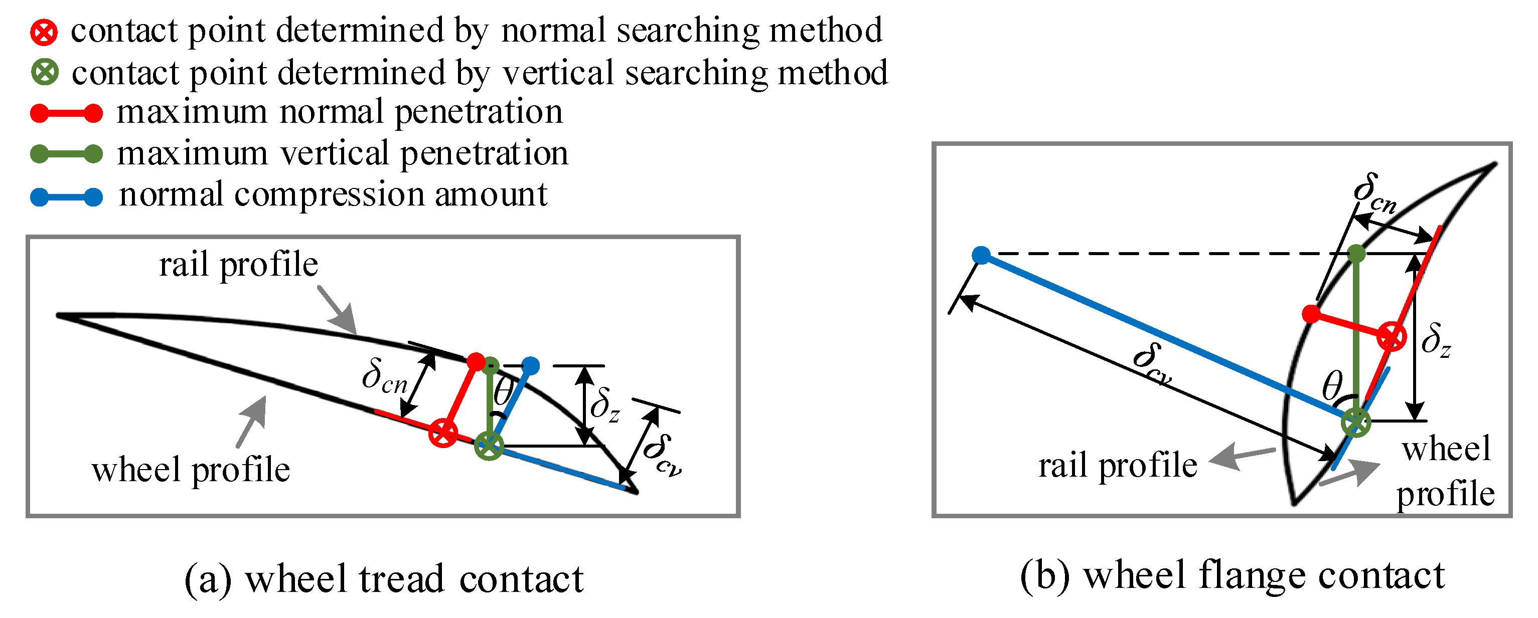
The potential contact points of each rolling circle form a space curve, namely, the contact trace, and it is then projected onto the rail cross-section. To determine the contact point position and the normal compression amount in the projection plane, the calculation methods based on the vertical searching method or normal searching method are adopted, as shown in Figure 2. In the normal searching method, for each discrete point on the wheel and rail profiles, the distance from the normal to another profile curve is defined as the normal penetration amount. The maximum normal penetration is adopted for the judgement of the contact point position and the determination of the normal compression amount, which is characterized by the length of the red line segment shown in Figure 2. The mathematical expression can be written as:
δ c n = m a x ( d n )
where d n represents the normal penetration amount.
In the vertical searching method, the maximum wheel-rail vertical penetration is introduced as the judgement condition when determining the contact point, which is characterized by the length of the green line segment shown in Figure 2. The normal compression amount can be determined by constructing a right triangle, as characterized by the length of the blue line segment shown in Figure 2. The mathematical expression is given as:
δ c v = δ z / cos θ
where δ z is the maximum vertical penetration amount, and θ is equal to δ w ϕ w .
In the wheel tread penetration zone, as presented in Figure 2a, since θ is small, the difference between δ c n and δ c v is not evident, indicating that the algorithm based on the vertical penetration is applicable in this case. In the wheel flange penetration zone, as shown in Figure 2b, δ c v is significantly different from δ c n in this case due to the significant impact of θ . Hence, using the algorithm based on the vertical penetration tends to cause large calculation errors of the normal compression amount in this case.
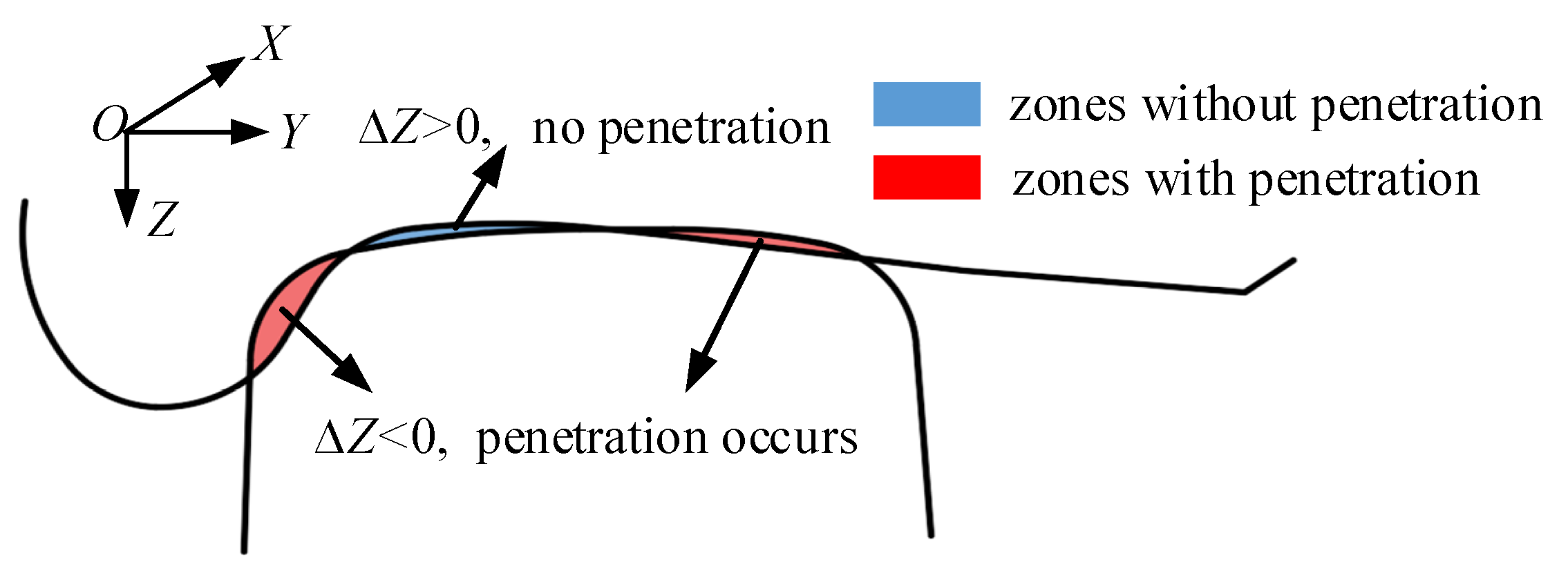
In addition, for the consideration of the number of wheel-rail contact points, if only single-point contact is considered, the position corresponding to the maximum penetration in the whole range of wheel tread is generally regarded as the wheel-rail contact point. In contrast, to consider multipoint contact, the segment searching method can be introduced to determine each wheel-rail penetration zone, as illustrated in Figure 3. For each discrete point on the wheel profile, its vertical coordinate is denoted by Z w , and the rail vertical coordinate corresponding to the vertical direction is denoted by Z r . The difference between the two vertical coordinates is denoted by Z and can be expressed as:
Z = Z w Z r
Thus, each wheel-rail penetration zone can be determined when Z < 0 . The contact point position and the normal compression amount can be determined in each penetration zone.

2.2. Wheel-Rail Contact Force Calculation

The wheel-rail normal contact force based on the Hertz elasticity theory is given as:
F N = K n r δ c 3 / 2
where K n r is the wheel-rail normal contact stiffness, and δ c is the wheel-rail normal compression amount.
According to an empirical formula, K n r is expressed as:
K n r = 1 / G 3 / 2
where G is the wheel-rail contact constant ( m / N 2 / 3 ) .
In contrast, the general expression for K n r derived from the Hertz theory is given as [24]:
K n r = 2 2 3 q k δ 1 + δ 2 ρ R w x 1 / 2 R w x
where δ 1 and δ 2 are the calculated parameters related to the Poisson’s ratio and elastic modulus of the wheel and rail; ρ is the parameter related to R w y and R r y at the contact points; R w y and R r y are the curvature radii of the wheel and rail profiles; and R w x is the rolling circle radius of the wheel. ρ / R w x is obtained from the corresponding calculation table. The intermediate calculation parameter q k is expressed as:
q k = m / 2 K ( e ) 3 / 2
where m and K ( e ) are the intermediate parameters in the solution obtained using the Hertz theory.
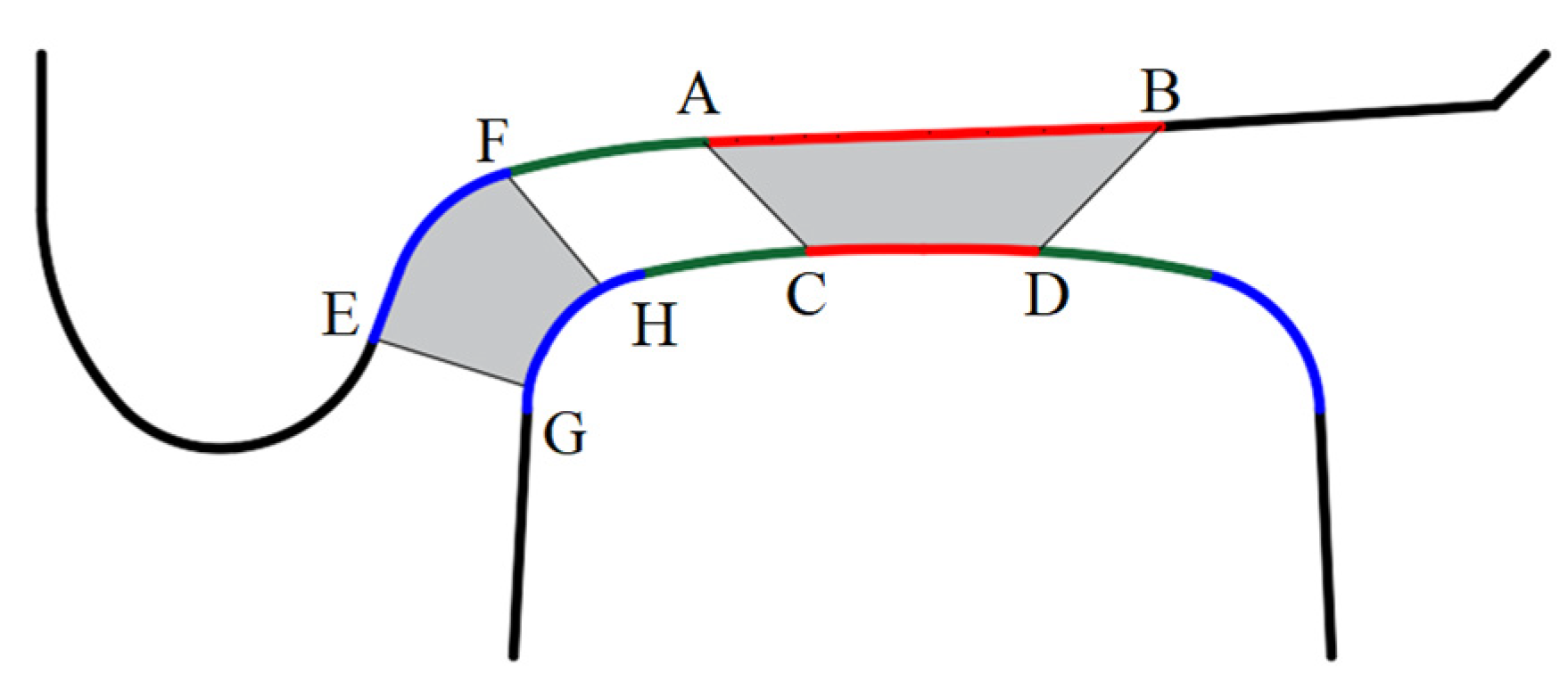
To clarify the difference between the empirical formula and the theoretical formula, the cases of wheel-tread contact and wheel-flange contact were analyzed. The different colored line segments on the wheel and rail profiles represent areas with different curvature radii in Figure 4. For wheel-tread contact, the contact points on the wheel and rail are located on lines AB and CD, respectively, as shown in Figure 4. In this case, the applicability of the empirical formula has been verified [24]. In contrast, for wheel-flange contact, the contact points are located on the lines EF and GH, respectively, as shown in Figure 4. In this case, R w y and R r y at the contact points are significantly different from that in wheel-tread contact. When using the theoretical formula, the calculation result of K n r must be significantly different from that in wheel-tread contact according to Equation (8). However, K n r will not change compared to that in wheel-tread contact when using the empirical formula according to Equation (7). Hence, using the empirical formula tends to cause large calculation errors of normal contact stiffness in this case.
After obtaining the normal contact force within each contact patch, the wheel-rail tangential force is first calculated using Kalker linear theory [29]. Considering the nonlinear relationship between wheel-rail creepages and creep forces for large creepages, the Shen-Hedrick-Elkins theory [5] is applied for the nonlinear correction of the tangential contact force.
Thus, the wheel-rail contact forces in each contact patch can be calculated, represented by blue line segments with arrows in Figure 5. Notably, the contact forces should be converted to an absolute coordinate system in dynamic analysis, which is given as:
F Y = F Y i ,   F Z = F Z i ,   M X = M X i ,   M Z = M Z i ( i = 1,2 , n )
where F Y , F Z , M X and M Z are composed by the wheel rail contact force and spin moment; i is the indicator of each wheel-rail contact point, and n is the number of contact points; and F Y i , F Z i , M X i and M Z i can be expressed as:
F X i = F N i · i + F x i · i + F y i · i , F Y i = F N i · j + F x i · j + F y i · j F Z i = N i · k + F x i · k + F y i · k , M X i = M i · i , M Z i = M i · k
where ( i , j, k) is the unit vector in the absolute coordinate system; F N i , F x i , F y i , and M i are the contact force and spin moment vectors at the ith wheel-rail contact point.
Figure 5. Wheel-rail contact force in the contact patch.
Applsci 13 05230 g005

3. Dynamic Analysis Model of Train-Track Coupling System under Earthquakes

The dynamic analysis model of the train-track coupling system under the effect of earthquakes is used for analysis of the influence of different algorithms on wheel-rail contact dynamics and running safety, as presented in Figure 6. The coupling system is divided into two subsystems: a train subsystem and a track subsystem. The subsystems are coupled by wheel-rail interaction. Earthquake excitations are applied to the bottom of the track. The vibration equation of the coupling system can be written as:
M v 0 0 M r X ¨ v X ¨ r + C v 0 0 C r X ˙ v X ˙ r + K v 0 0 K r X v X r = F v g + F w F r + F E A
where M v , C v , and K v represent the mass, damping, and stiffness matrices of the train subsystem, respectively; X v represents the displacement vector of the train subsystem; M r , C r , and K r represent the mass, damping, and stiffness matrices of the track subsystem, respectively; X r represents the displacement vector of the track subsystem; F v g represents the self-weight load vector of the train system; F w and F r represent the load vectors of the wheel-rail force applied to the train subsystem and track subsystem, respectively; and F E A is the earthquake load obtained using the large mass method [30].

3.1. Train Subsystem

Each vehicle of a train can be simplified as a vibration system comprising vehicle body, bogies, wheelsets, and double-suspension systems, as shown in Figure 7. Four degrees of freedom, namely, vertical movement, lateral movement, rolling, and yawing, are considered for each wheelset, and for the vehicle body and each bogie, the degree of freedom of pitching is considered in addition to the former four degrees of freedom. To accurately simulate the motion behavior of vehicles under extreme conditions, such as during an earthquake, the nonlinearity of the secondary lateral stop, spring stiffness, and damping of the suspension systems [31,32,33], is considered in this paper. Thus, the vibration equation of the train subsystem can be given as:
M v X ¨ v + C v X ˙ v + K v X v = F v g + F w
where the definitions of each variable are the same as that given for Equation (12).

3.2. Track Subsystem

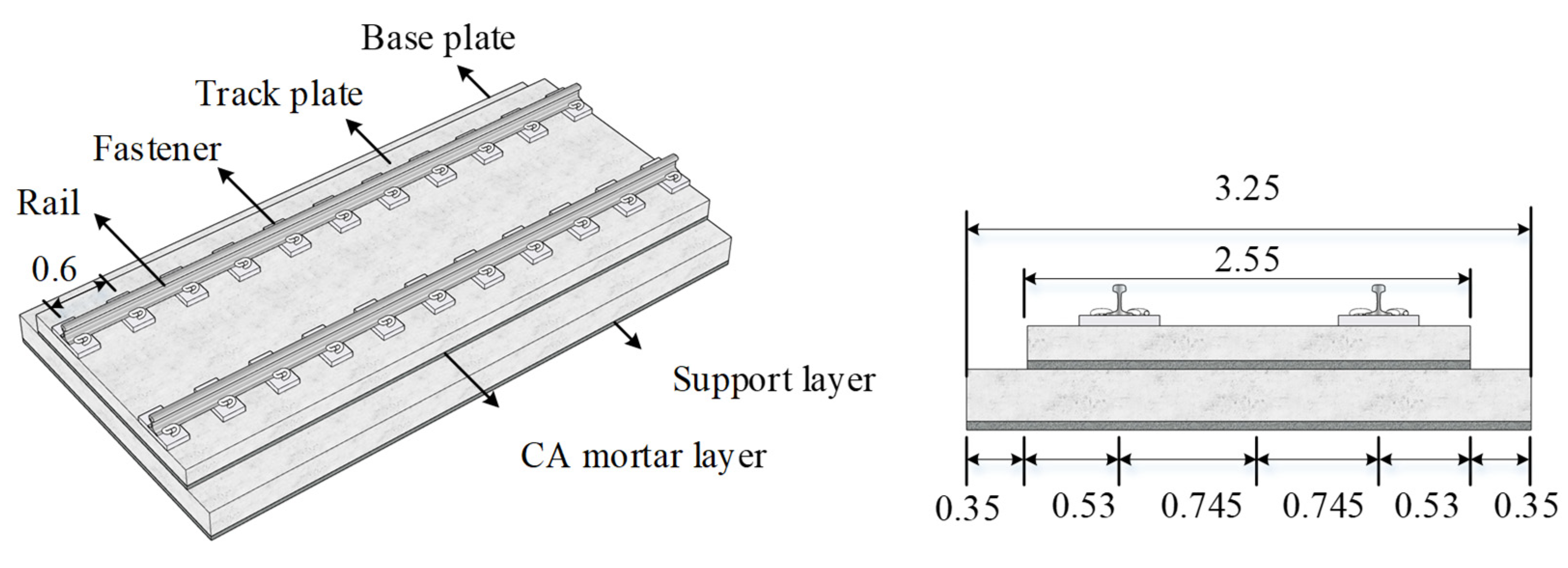
The China Railway Track System II (CRTS II) slab ballastless track structure was adopted in this study, the main construction and dimensions of which are shown in Figure 8. This type of ballastless track was derived from German Borg slab ballastless track structure and developed in China, which can provide a more stable, durable, and lower maintenance alternative to traditional ballasted track systems [34]. It has been widely used in China’s high-speed rail line, including the Beijing-Tianjin Intercity Railway and the Beijing-Shanghai High-Speed Railway [35]. The track structure was established using the finite element (FE) method. For the modeling, the rail was built using beam element, the track plate and base plate were built using shell element, and the fastener was simulated by a spring damping element. The CA mortar layer and support layer were simulated by uniformly distributed spring damping element. The vibration equation of the track subsystem under earthquakes is given as:
M r X ¨ r + C r X ˙ r + K r X r = F r + F E A
where the definitions of each variable are the same as that given for Equation (12).

3.3. Train-Track Coupling

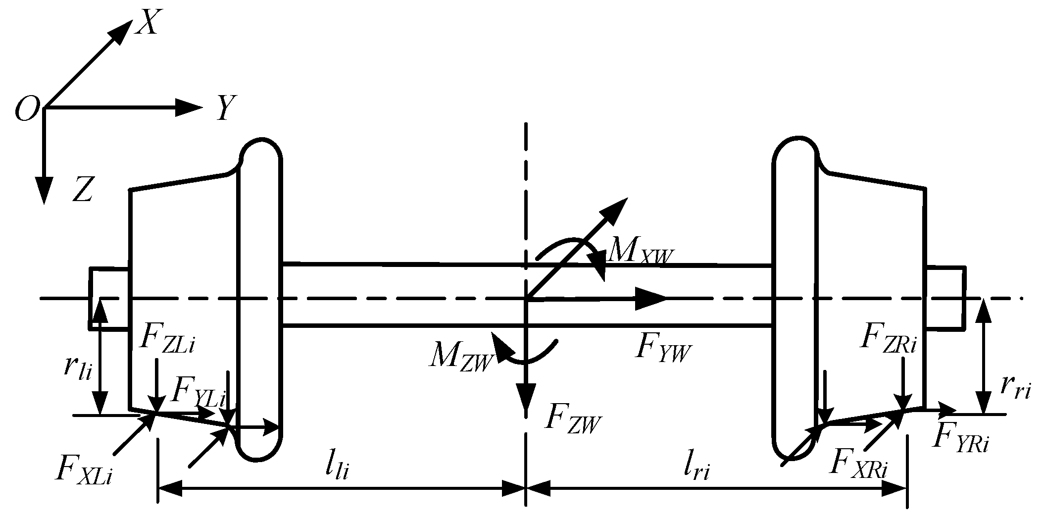
Figure 9 shows a scheme of the force state of each wheelset in the train subsystem. The loads at the wheelset centroid can be expressed as:
F Y w = F Y L i + F Y R i , F Z w = F Z L i + F Z R i , M X w = F Z L i · l l i F Y L i · r l i + F Z R i · l r i F Y R i · r r i + M X L i + M X R i M Z w = F X L i · l l i + F Y L i · l l i · ψ w + F X R i · l r i + F Y L i · l l i · ψ w + M Z L i + M Z R i ( i = 1,2 , n )
where F Y w , F Z w , M X w , and M Z w are the lateral force, vertical force, rolling moment, and yawing moment at the wheelset centroid, respectively; F X ( L , R ) i , F Y ( L , R ) i , F Z ( L , R ) i , M X ( L , R ) i , and M Z ( L , R ) i can be obtained by Equation (11).
F w in Equation (13) can be written as:
F w = [ F w 1 , F w 2 , , F w j ] T ( j = 1,2 , , m )
where m is the number of vehicles, and F w j is expressed as:
F w j ( 1 × 31 ) = F c j , F b j 1 , F b j 2 , F w j 1 , , F w j k T ( k = 1,2 , 3,4 )
where F c j , F b j ( 1,2 ) , F w j k are the load vectors corresponding to the vehicle body, bogies, and the kth wheelset of the jth vehicle. F w j k can be written as:
F w j k ( 1 × 4 ) = [ F Y w , F Z w , M X w , M Z w ] T
In the track subsystem, taking the left rail as an example, the concentrated wheel-rail load applied to the rail can be expressed as:
F Y r = F Y L i ,   F Z r = F Z L i
Here, F Y r and F Z r represent the lateral and vertical forces, respectively; F Y L i and F Z L i are the same as that in Equation (15).
The node load vector of the rail element is expressed as:
F r e ( 1 × N r ) = [ F Y r   F Z r ] T · N x
where N x represents the vector of the cubic Hermit form functions corresponding to the cell nodes, and N r is the number of degrees of freedom of each node.
F r e ( 1 × N r ) is applied to the corresponding degrees of freedom; thus, F r in Equation (14) can be established.

4. Comparison of Different Wheel-Rail Contact Models

To analyze the impact of different algorithms on wheel-rail contact dynamics, different wheel-rail contact models were established based on the corresponding algorithms. By considering single-point contact, calculating normal compression amount based on vertical penetration and adopting the empirical formula for normal contact stiffness calculation, the corresponding wheel-rail contact model was established. This model was designated as Model 1. Similarly, different wheel-rail contact models were established, as listed in Table 1. The effect of considering multipoint contact versus single-point contact can be clarified by comparing Models 1 and 2. The effect of different algorithms for wheel-rail normal compression amount can be clarified by comparing Models 2 and 3, while the effect of different calculation formulae for the normal contact stiffness can be clarified by comparing Models 3 and 4.
A single CRH2 motor vehicle passing through the CRTS II slab ballastless track was taken as the example. The train running speed was set to 300 km/h. LMA and CHN60 were adopted as the wheel and rail profiles, respectively, as presented in Figure 10.
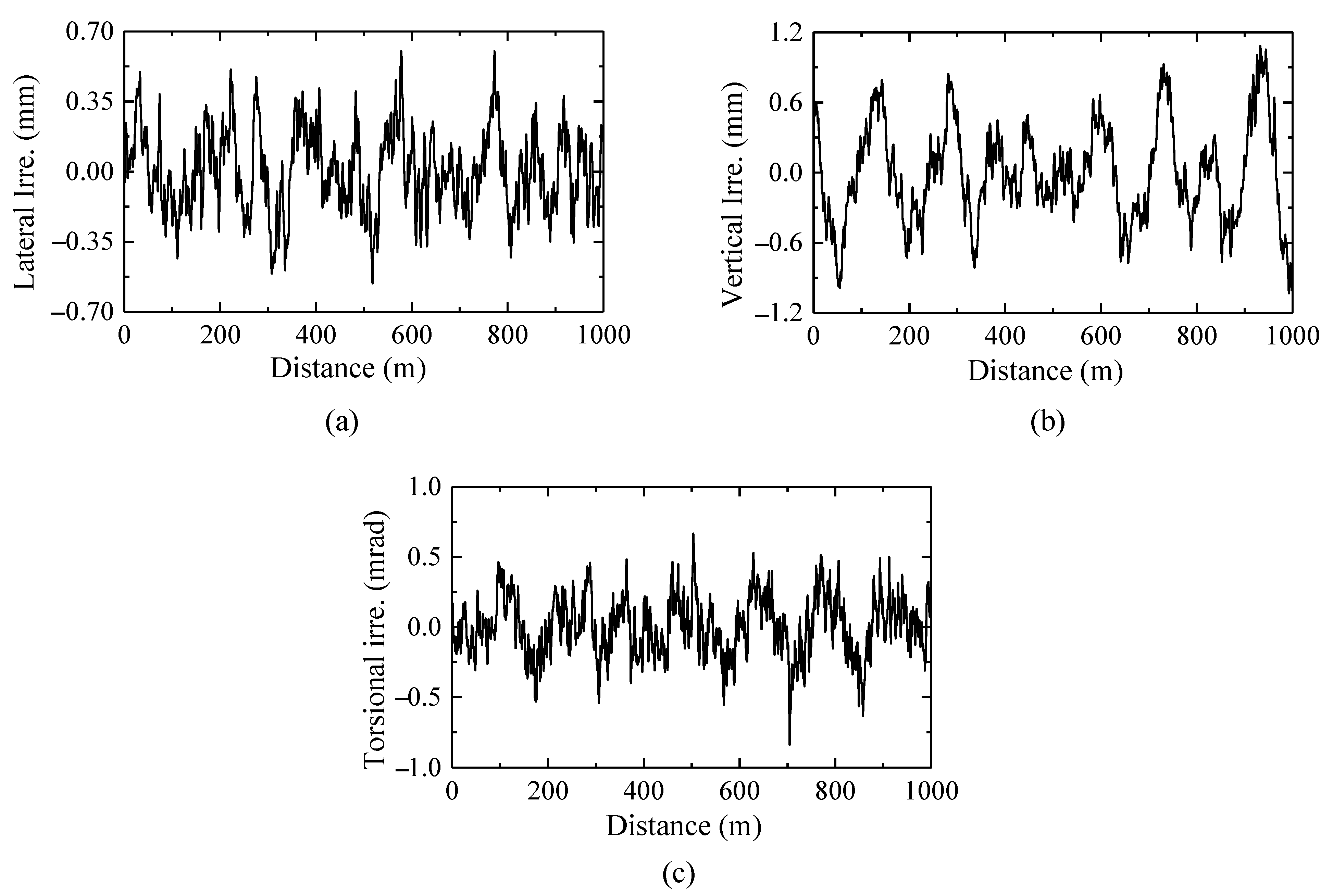
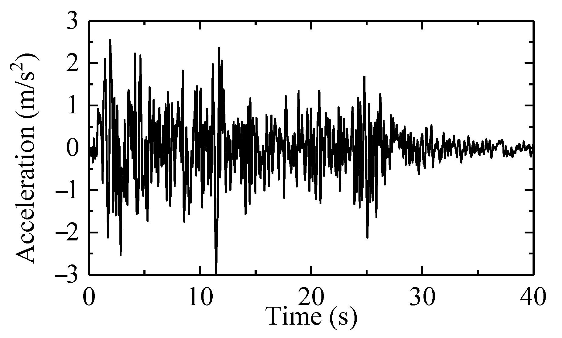
A comparative analysis under ordinary and seismic conditions was conducted. Under the seismic condition, the track irregularity excitation was considered; Figure 11 shows the irregularity samples. Since the wheel-rail dynamic response is mainly influenced by transverse excitations of earthquakes [36], only the transverse excitations were considered in this study. The El-Centro wave, generated by the 6.5 magnitude earthquake that took place in California, United States on 18 May 1957, has distinctive waveform characteristics that make it one of the frequently utilized seismic waves in the field of train-running safety under earthquakes [37,38]. The acceleration time history of this earthquake wave was obtained from the Pacific Earthquake Engineering Research (PEER) Ground Motion Database, and the peak acceleration was adjusted to 0.3 g as the ground motion input, as shown in Figure 12. For ordinary conditions, only track irregularity excitation was considered.

4.1. Comparison under Ordinary Conditions

To verify the correctness of the four models and to analyze the applicability of the wheel-rail contact algorithms under ordinary conditions, the wheel-rail contact dynamics on the left wheel of the first wheelset calculated based on the different models were compared, as shown in Figure 13.
Figure 13a,b show that the time histories of F Y and F Z based on the different models are in good agreement, thus verifying the correctness of the established models. As presented in Figure 13c, K n r calculated based on Model 1 is maintained at 11.52 × 10¹⁰ N/m3/2. In contrast, when calculating based on Model 4, this value is maintained at 9.20 × 10¹⁰ N/m3/2 due to the straight segment of the wheel tread keeping in contact with the R300 arc segment of the rail head. Figure 13d shows a slight difference in δ c calculated based on Models 1 and 4. Moreover, although the empirical formula causes a calculation error for K n r and δ c , it has largely no impact on the contact force. Thus, it can be concluded that under this condition, it is applicable to adopt the normal compression algorithm based on vertical penetration, the empirical formula for calculating the normal contact stiffness, and only consider single-point contact.

4.2. Comparison under Seismic Conditions

4.2.1. Wheel-Rail Contact Dynamics

The wheel-rail dynamic responses on the left side of the first wheelset calculated based on the different models were compared under seismic conditions firstly. The calculation results based on Models 1–4 are denoted by R 1 , R 2 , R 3 , and R 4 , respectively.
To clarify the effect of considering multipoint contact versus single-point contact, the wheel-rail dynamic responses calculated on the basis of Models 1 and 2 are compared, as shown in Figure 14 and Figure 15. The relative calculation error between the two models can be expressed as ( R 1 R 2 ) / R 2 × 100 % . Figure 14 shows that the differences in F Y and F Z that were calculated based on Models 1 and 2 mainly occur during the period when the contact force surges, i.e., when the wheel-flange contact occurs.
Figure 15 shows the wheel-rail contact states obtained at a time of 3.80 s based on the two models. The wheel profile and rail profile are represented by red and blue curves respectively in Figure 15. In this case, the two-point contact state can be simulated based on Model 2 while the contact area existing in the wheel tread region is ignored when Model 1 is used. The solutions to F Z based on Models 1 and 2 are 221.78 kN and 258.16 kN, respectively, with a calculated relative error of −14.09%, and the solutions to F Y based on Models 1 and 2 are 130.20 kN and 76.98 kN, respectively, with a calculated relative error of 69.13%. Considering single point contact only will adversely affect the simulation of the wheel-rail contact state. Hence, multipoint contact should be considered under seismic conditions.
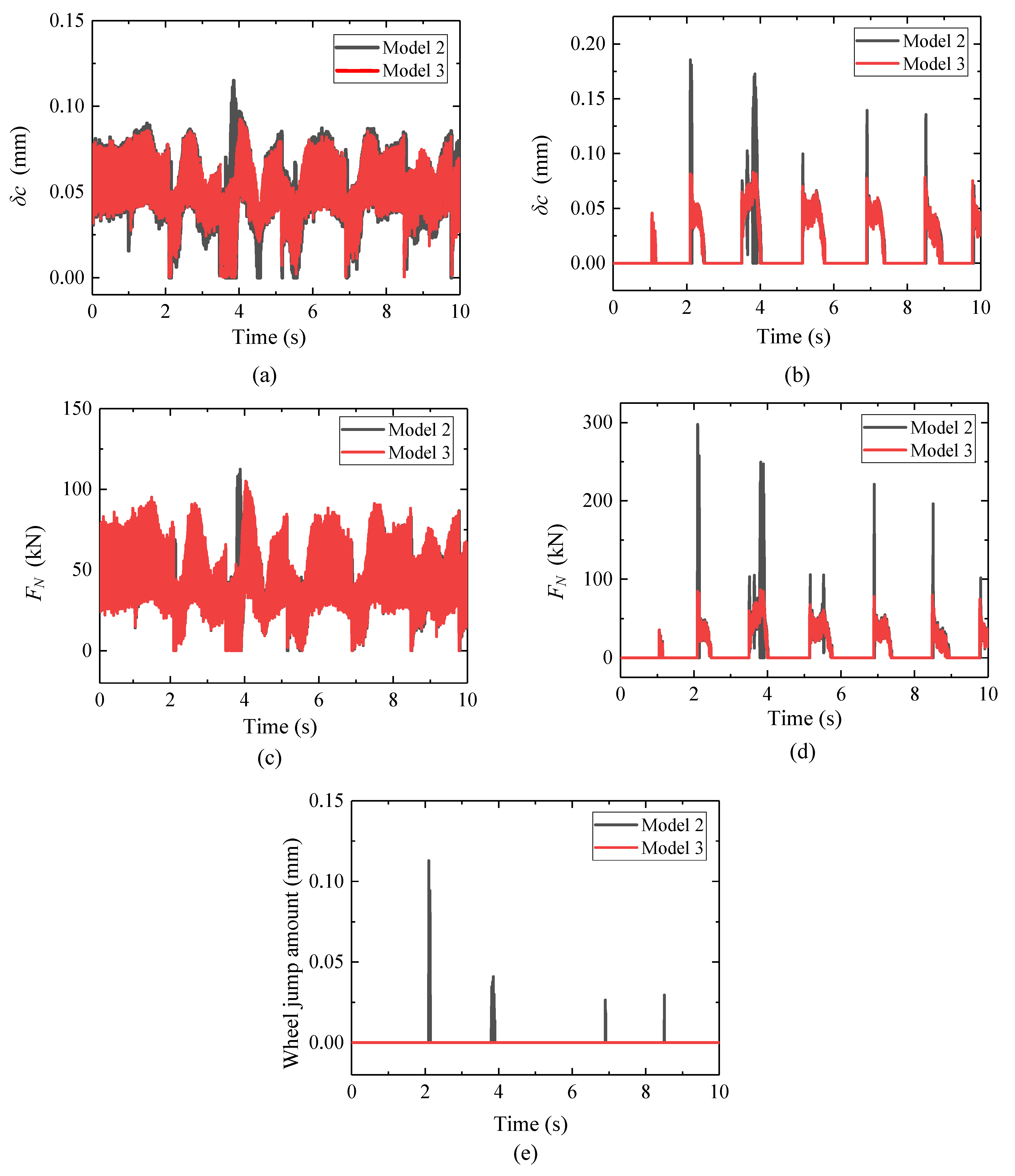
To clarify the effect of different algorithms for the wheel-rail normal compression amount, the wheel-rail dynamic responses calculated based on Models 2 and 3 are compared, as shown in Figure 16. Both wheel-tread contact region and flange-root contact region are considered as wheel-rail contact potential areas, which are recorded as region 1 and region 2, respectively. From Figure 16a,b, it can be found that the difference in δ c based on the two models is mainly reflected in region 2, where the maximum values of δ c obtained based on Models 2 and 3 are 0.186 mm and 0.083 mm, respectively, and the former is 2.24 times that of the latter. From Figure 16c,d, it is observed that the trend in F N is consistent with δ c since the same calculation formula for K n r is adopted. The maximum values of F N calculated based on Models 2 and 3, are 297.72 kN and 87.02 kN, respectively, in region 2, and the former is 3.42 times that of the latter. In addition, the wheel jumping amount, defined as the maximum vertical distance between the wheel and rail without wheel-rail contact occurring, was also introduced as an indicator of wheel rail dynamic response here. The responses of the wheel jump amount are given, as depicted in Figure 16e. Wheel jump is consistent with the occurrence of the contact in region 2 based on Model 2, which means that an unreasonable surge in the wheel-rail contact force will lead to an unreasonable wheel jump. Hence, the algorithm for the wheel-rail normal compression amount based on normal penetration should be introduced to avoid any unreasonable surge in the wheel-rail normal contact force.
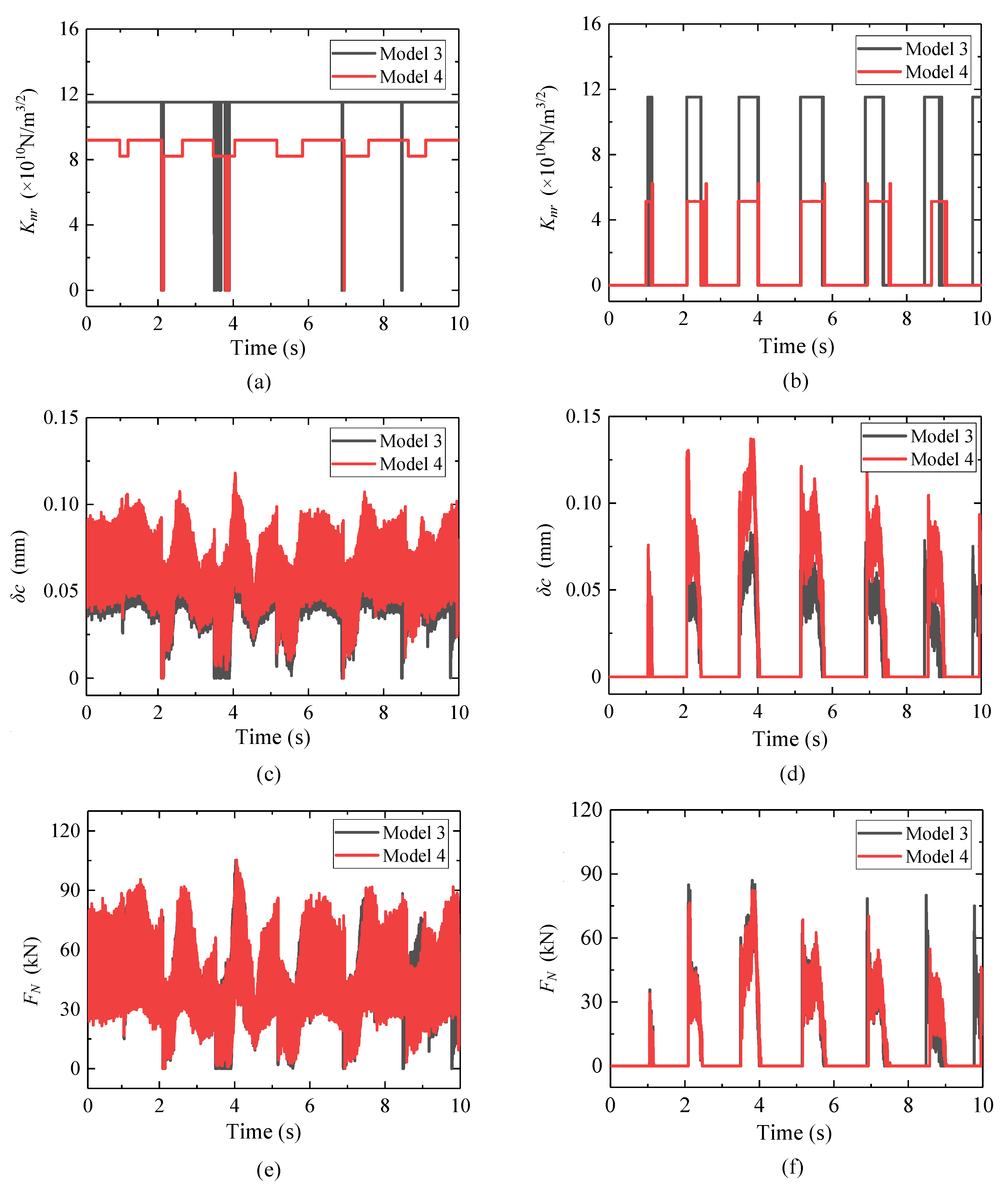
To clarify the influence of different calculation formulae for the normal contact stiffness, the wheel-rail dynamic responses calculated based on Models 3 and 4 are compared, as plotted in Figure 17. For the contact in region 1, Figure 17a shows that based on Model 4, when contact occurs between the straight-line segment of the wheel tread and the R300 arc segment of the rail head, K n r is maintained at 9.20 × 10¹⁰ N/m3/2. When contact occurs between the R450 arc segment of the wheel tread and the R300 arc segment of the rail head, K n r decreases to 8.21 × 10¹⁰ N/m3/2. Figure 17c,e show that the theoretical formula also causes a difference in δ c , but has no significant effect on F N , which is consistent with the phenomenon observed under ordinary conditions. For the contact in region 2, the solutions to K n r based on Models 3 and 4 are significantly different, as presented in Figure 17b. In this case, the contact mainly occurs between the R14 arc segment of the wheel flange root and the R13 arc segment of the rail gauge corner. The calculation result of K n r based on the theoretical formula is 5.13 × 10¹⁰ N/m3/2, which is approximately half of that based on the empirical formula. A different calculation formulae for K n r will cause significant differences in δ c , as shown in Figure 17d. Consequently, there is a noticeable difference after 8 s, as shown in Figure 17f. Therefore, to ensure the reliability of the normal contact force calculation, the theoretical calculation formula for the normal contact stiffness should be introduced.
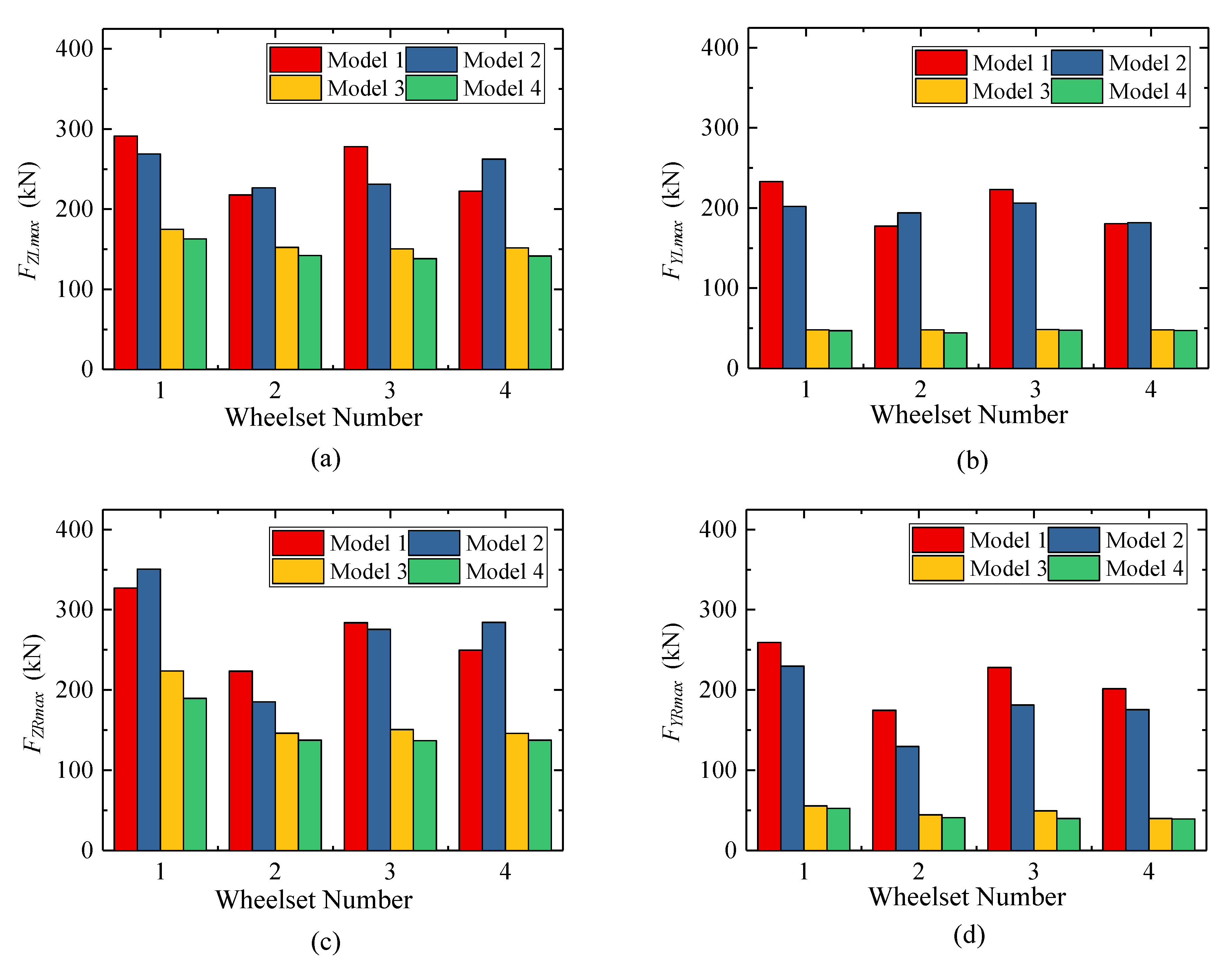
To clarify the significance of the effect of the normal compression algorithms, the normal contact stiffness algorithms, and the considerations of the number of the contact point, the maximum values of wheel-rail forces on both sides of the four wheelsets calculated on the basis of the different models are presented in Figure 18. The relative calculation errors can be expressed as: 12 = ( R 1 R 2 ) / R 2 × 100 % , 23 = ( R 2 R 3 ) / R 3 × 100 % and 34 = ( R 3 R 4 ) / R 4 × 100 % . As shown in Figure 18, the algorithm for the normal compression amount has the most significant impact on the F Z and F Y solutions, with 23 ranging from 48.97% to 339.50%. Regarding the impact of considering the wheel-rail contact point, considering only single-point contact may cause F Z and F Y to increase or decrease, with 12 ranging from −15.26% to 35.00%. The impact of the normal contact stiffness algorithm is minimal, with 34 ranging from 6.04% to 23.55%.

4.2.2. Running Safety Assessment

In order to clarify the impact of different models on the running safety of trains during earthquakes, the calculation results of the running safety indices and running safety assessment results based on different models were compared. Three indices were adopted in this study: (i) derailment coefficient (Q/P), (ii) wheel unloading rate (∆P/P), and (iii) wheelset lateral force (∑Q). According to the Technical Code for Dynamic Acceptance of High-Speed Railway Engineering (TB10761-2013), the limit values of each index are listed in Table 2.
Table 3 shows the maximum values of the three running safety indices calculated based on different models. The results demonstrate that the selection of algorithms in wheel-rail contact modelling has a significant effect on the safety assessment of trains during earthquakes. All the indices calculated based on Models 1 and 2 exceed their limits, indicating that the train has entered a dangerous state of operation. In comparison, all the indices calculated based on Models 3 and 4 are within the safe range, indicating that the train is in a safe state of operation. Comparing the results of Models 1 and 2, the relative calculation errors of Q/P, ∆P/P, and ∑Q reach to −4.60%, −5.0%, and −8.84%, respectively. This finding indicates that the running safety of trains during earthquakes is underestimated when considering only the single-point wheel-rail contact. Comparing the results of Models 2 and 3, the relative calculation error of Q/P, ∆P/P, and ∑Q reach to 11.54%, 20.99%, and 432.09%, respectively. This finding indicates that calculating the wheel-rail normal compression based on vertical penetration will significantly overestimate the running safety indices under earthquakes, leading to misjudgment of the running safety of trains. Comparing the results of Models 3 and 4, there is no significant difference in the indices, indicating that although using an empirical formula for wheel-rail normal contact stiffness will have a certain impact on the calculation accuracy of wheel-rail contact force, the influence on the calculation results of the running safety assessment of trains under earthquakes is small.

5. Model Validation

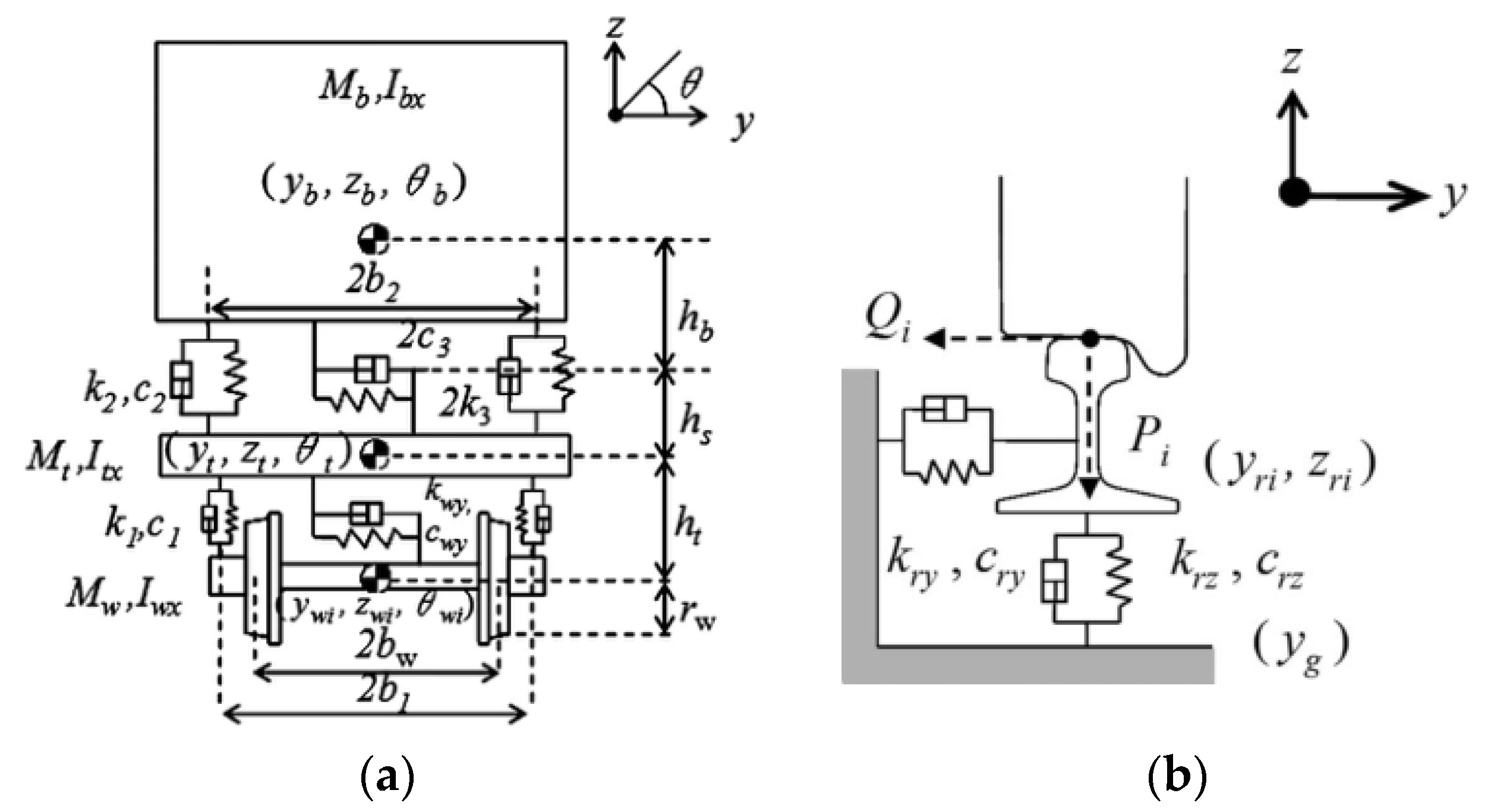
Through the analysis in Section 4, Model 4 should be the most reasonable choice as the wheel rail contact model under earthquake excitations. In order to verify the correctness of the model, the calculation results of wheel-rail contact force based on the model established in this paper were compared with those given in the study of Nishimura et al. [33]. Nishimura et al. simplified the vehicle as a system consisting of four rigid bodies, including a body, a frame, and two wheelsets. They considered the lateral, sinking, and rolling movements of each rigid body and assumed that the two wheelsets had the same motion state, establishing a 9-degree of freedom vehicle model. Furthermore, they also considered the lateral and vertical degrees of freedom of the rail, resulting in a comprehensive vehicle dynamic simulation model with a total of 13 degrees of freedom (as shown in Figure 19). The correctness of this model was verified through shaking table tests [39].
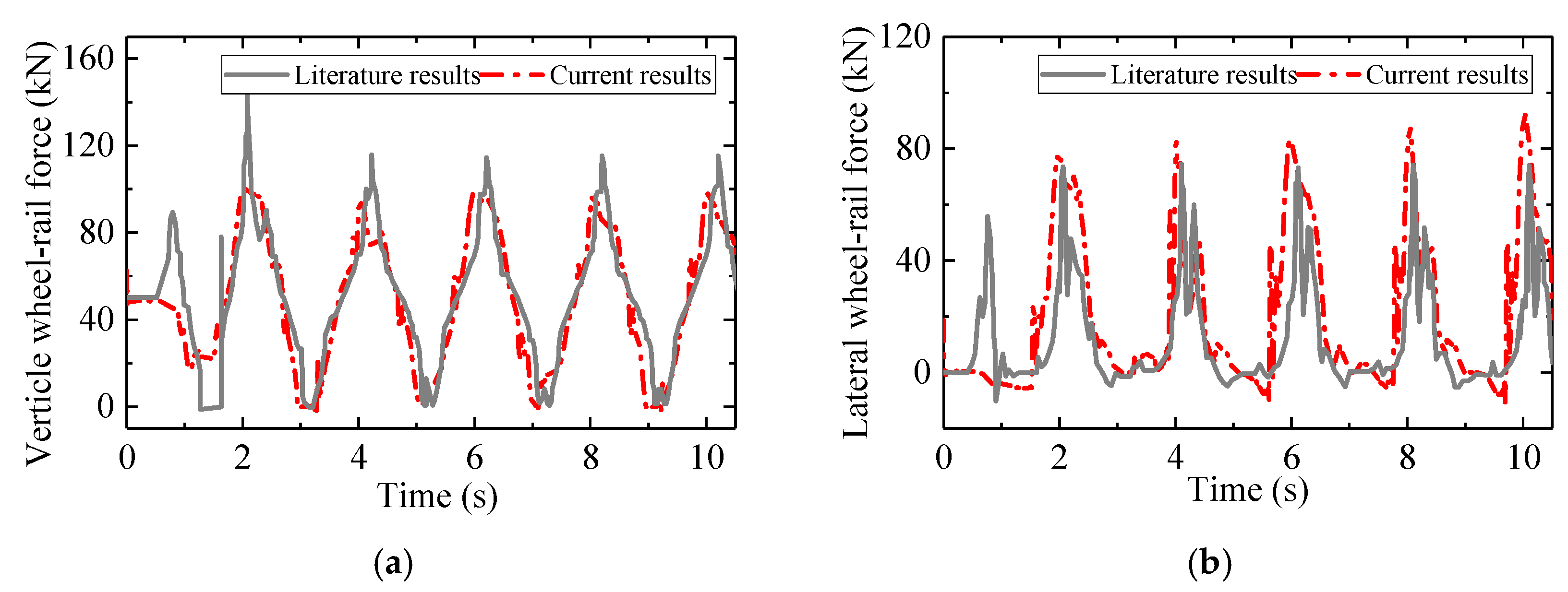
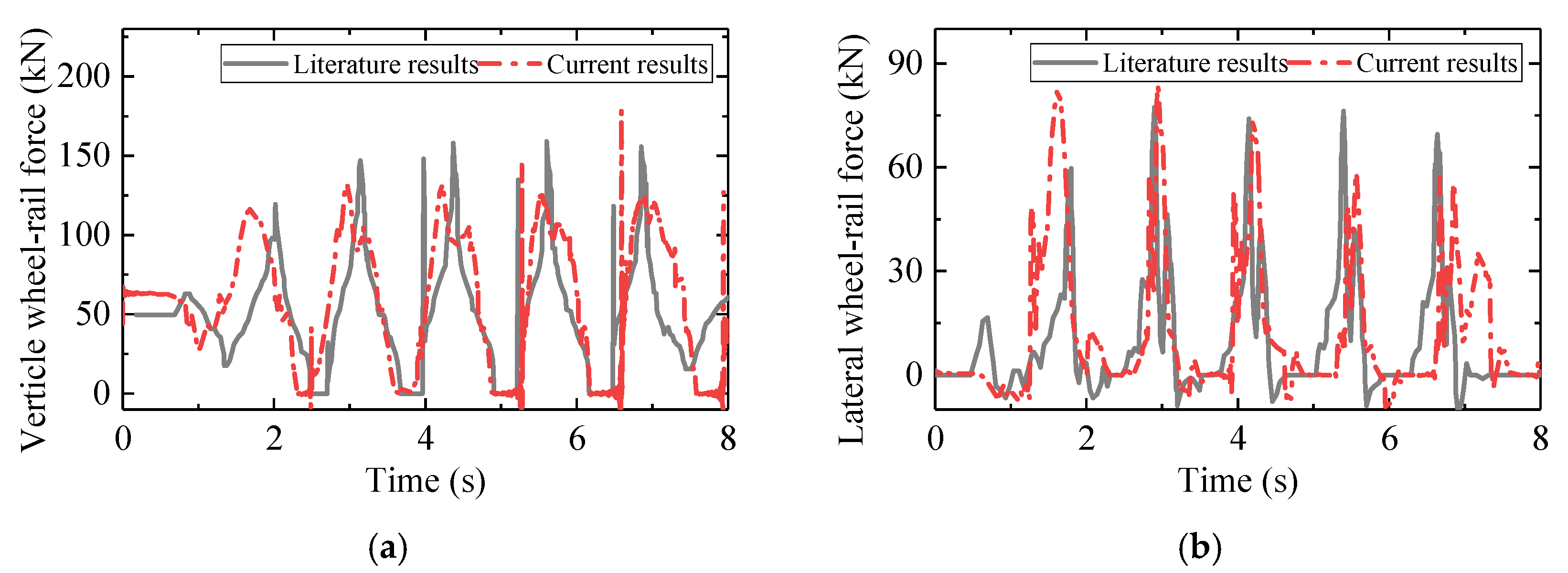
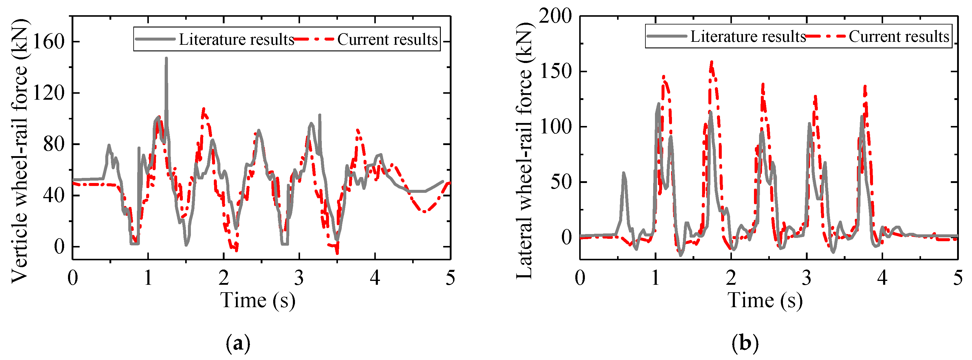
Taking five-circle sine waves with frequencies of 0.5 Hz, 0.8 Hz, and 1.5 Hz as excitation, the wheel rail force calculation results are shown in Figure 20, Figure 21 and Figure 22. It can be seen that the time histories of the vertical and lateral wheel-rail forces calculated based on this article are in good agreement with those presented in the literature, thus verifying the correctness and effectiveness of the model established in this article.

6. Conclusions

This paper investigated the effects of different normal compression algorithms, normal contact stiffness algorithms, and considerations of single-point/multi-point contact on the running safety assessment of trains under earthquakes. Through a case study of a single CRH2 train passing over a CRTS II type slab track structure under El-Centro wave excitation, a comparative analysis of the effect of different algorithms on the wheel-rail contact dynamics and running safety was conducted. The findings provided recommendations for the selection of wheel-rail contact algorithms under earthquakes. The main conclusions are as follows:
  • Using different wheel-rail contact algorithms will significantly affect the calculation accuracy of wheel-rail force in the case of flange-root contact under earthquakes. The most significant influence is due to the normal compression algorithm. Using an algorithm based on vertical penetration can lead to a maximum relative error of 339.50% for the case considered in this study. The consideration of the number of wheel-rail contact points also has a notable impact, with a maximum relative error of 35.00% caused by only considering single point contact. The influence of the normal contact stiffness algorithm is the least significant, with a maximum relative calculation error of 23.55% caused by using the empirical formula.
  • Using different wheel-rail contact algorithms will have a significant impact on the indices of running safety assessment under earthquakes. Using wheel-rail normal compression algorithm based on vertical penetration will significantly underestimating the train running safety margin, while only considering the wheel-rail single point contact will overestimate the train running safety margin, and using the wheel-rail normal contact empirical formula has little impact.
  • To ensure the accuracy of running safety assessment of trains under earthquakes, it is recommended to use the normal compression algorithm based on normal penetration and consider multi-point contact in wheel-rail contact modelling.

Author Contributions

Conceptualization, Z.Z.; methodology, G.C. and Z.Z.; formal analysis, G.C.; writing-original draft preparation, G.C.; writing-review and editing, W.G. and G.Z.; supervision, L.J. and B.Y.; funding acquisition, Z.Z. All authors have read and agreed to the published version of the manuscript.

Funding

This study was funded by the National Natural Science Foundation of China (Grant No. 52078498), Natural Science Foundation of Hunan Province of China (Grant number: 2022JJ30745), Frontier cross research project of Central South University (Grant number: 2023QYJC006), Science and Technology Research and Development Program Project of China railway group limited (Major Special Project, No.: 2021-Special-04-2) and Hunan Provincial Science and Technology Promotion Talent Project (Grant number: 2020TJ-Q19).

Institutional Review Board Statement

Not applicable.

Informed Consent Statement

Not applicable.

Data Availability Statement

No new data were created in this study.

Conflicts of Interest

The authors declare that they have no known competing financial interests or personal relationships that could have appeared to influence the work reported in this paper.

References

  1. Cao, L.C.; Yang, C.W.; Zhang, J.J. Derailment Behaviors of the Train-Ballasted Track-Subgrade System Subjected to Earthquake Using Shaking Table. KSCE J. Civ. Eng. 2020, 24, 2949–2960. [Google Scholar] [CrossRef]
  2. Zeng, Q.; Dimitrakopoulos, E.G. Vehicle-bridge interaction analysis modeling derailment during earthquakes. Nonlinear Dyn. 2018, 93, 2315–2337. [Google Scholar] [CrossRef]
  3. Meymand, S.Z.; Keylin, A.; Ahmadian, M. A survey of wheel-rail contact models for rail vehicles. Veh. Syst. Dyn. 2016, 54, 386–428. [Google Scholar] [CrossRef]
  4. Chen, H.Y.; Jiang, L.Z.; Li, C.Q.; Li, J.; Shao, P.; He, W.K.; Liu, L.L. A semi-online spatial wheel-rail contact detection method. Int. J. Rail Transp. 2021, 10, 730–748. [Google Scholar] [CrossRef]
  5. Shen, Z.Y.; Hedrick, J.K.; Elkins, J.A. A comparison of alternative creep force models for rail vehicle dynamic analysis. Veh. Syst. Dyn. 1983, 12, 79–83. [Google Scholar] [CrossRef]
  6. Luo, J.; Zhu, S.Y.; Zhai, W.M. An advanced train-slab track spatially coupled dynamics model: Theoretical methodologies and numerical applications. J. Sound Vib. 2021, 501, 116059, 1–30. [Google Scholar] [CrossRef]
  7. Zhai, W.M.; Han, Z.Y.; Chen, Z.W.; Ling, L.; Zhu, S.Y. Train-track-bridge dynamic interaction: A state-of-the-art review. Veh. Syst. Dyn. 2019, 57, 1–44. [Google Scholar] [CrossRef]
  8. Xu, L.; Zhai, W.M. Train-track coupled dynamics analysis: System spatial variation on geometry, physics and mechanics. Railw. Eng. Sci. 2020, 28, 36–53. [Google Scholar] [CrossRef]
  9. Liu, H.Y.; Yu, Z.W.; Guo, W.; Jiang, L.Z.; Kang, C.J. A novel method to search for the wheel-rail contact point. Int. J. Struct. Stab. Dyn. 2019, 19, 1950142, 1–21. [Google Scholar] [CrossRef]
  10. Xu, J.M.; Wang, P.; Ma, X.C.; Xiao, J.L.; Chen, R. Comparison of calculation methods for wheel-switch rail normal and tangential contact. Proc. Inst. Mech. Eng. Part F J. Rail Rapid Transit 2016, 231, 148–161. [Google Scholar] [CrossRef]
  11. Gong, W.; Zhu, Z.H.; Liu, Y.; Liu, R.T.; Tang, Y.J.; Jiang, L.Z. Running safety assessment of a train traversing a three-tower cable-stayed bridge under spatially varying ground motion. Railw. Eng. Sci. 2020, 28, 184–198. [Google Scholar] [CrossRef]
  12. Chen, L.K.; Kurtulus, A.; Dong, Y.F.; Taciroglu, E.; Jiang, L.Z. Velocity pulse effects of near-fault earthquakes on a high-speed railway vehicle-ballastless track-benchmark bridge system. Veh. Syst. Dyn. 2021, 60, 2963–2987. [Google Scholar] [CrossRef]
  13. Jin, Z.B.; Liu, W.Z. Fragility analysis for vehicle derailment on railway bridges under earthquakes. Railw. Eng. Sci. 2022, 30, 494–511. [Google Scholar] [CrossRef]
  14. Ling, L.; Xiao, X.B.; Wu, L.; Jin, X.S. Study on dynamic responses and running safety boundary of high-speed train under seismic motions. J. China Railw. Soc. 2012, 34, 16–22. (In Chinese) [Google Scholar]
  15. Zhao, H.; Wei, B.; Jiang, L.Z.; Xiang, P. Seismic running safety assessment for stochastic vibration of train-bridge coupled system. Arch. Civ. Mech. Eng. 2022, 22, 180, 1–24. [Google Scholar] [CrossRef]
  16. Yamashita, S.; Sugiyama, H. Numerical procedure for dynamic simulation of two-point wheel/rail contact and flange climb derailment of railroad vehicles. J. Comput. Nonlinear Dyn. 2012, 7, 041012, 1–7. [Google Scholar] [CrossRef]
  17. Ren, Z.S.; Iwnicki, S.D.; Xie, G. A new method for determining wheel-rail multi-point contact. Veh. Syst. Dyn. 2011, 49, 1533–1551. [Google Scholar] [CrossRef]
  18. Xiao, X.B.; Jin, X.S.; Wen, Z.F.; Zhu, M.H.; Zhang, W.H. Effect of tangent track buckle on vehicle derailment. Multibody Syst. Dyn. 2010, 25, 1–41. [Google Scholar] [CrossRef]
  19. Meli, E.; Ridolfi, A. An innovative wheel-rail contact model for railway vehicles under degraded adhesion conditions. Multibody Syst. Dyn. 2013, 33, 285–313. [Google Scholar] [CrossRef]
  20. Montenegro, P.A.; Neves, S.G.M.; Calçada, R.; Tanabe, M.; Sogabe, M. Wheel-rail contact formulation for analyzing the lateral train-structure dynamic interaction. Comput. Struct. 2015, 152, 200–214. [Google Scholar] [CrossRef]
  21. Magalhaes, H.; Marques, F.; Antunes, P.; Flores, P.; Pombo, J. Wheel-rail contact models in the presence of switches and crossings. Veh. Syst. Dyn. 2022, 61, 838–870. [Google Scholar] [CrossRef]
  22. Shabana, A.A.; Zaazaa, K.E.; Escalona, J.L.; Sany, J.R. Development of elastic force model for wheel/rail contact problems. J. Sound Vib. 2004, 269, 295–325. [Google Scholar] [CrossRef]
  23. Ling, L.; Jin, X.S. A 3D model for coupling dynamics analysis of high−speed train/track system. J. Zhejiang Univ. Sci.-A 2014, 15, 964–983. [Google Scholar] [CrossRef]
  24. Guan, Q.H.; Zhao, X.; Wen, Z.F.; Jin, X.S. Calculation Method of Hertzian Normal Contact Stiffness. J. Southwest Jiaotong Univ. 2021, 56, 883–890. (In Chinese) [Google Scholar]
  25. Shabana, A.A.; Berzeri, M.; Sany, J.R. Numerical Procedure for the Simulation of Wheel/Rail Contact Dynamics. J. Dyn. Syst. Meas. Control. 2001, 123, 168–178. [Google Scholar] [CrossRef]
  26. Pombo, J.; Ambrósio, J.; Silva, M. A new wheel–rail contact model for railway dynamics. Veh. Syst. Dyn. 2007, 45, 165–189. [Google Scholar] [CrossRef]
  27. Marques, F.; Magalhães, H.; Pombo, J.; Ambrósio, J.; Flores, P. A three-dimensional approach for contact detection between realistic wheel and rail surfaces for improved railway dynamic analysis. Mech. Mach. Theory 2020, 149, 1–28. [Google Scholar] [CrossRef]
  28. Zhai, W.M. Vehicle-Track Coupled Dynamics Theory and Applications; Springer: Singapore, 2019; pp. 56–122. [Google Scholar]
  29. Kalker, J.J. On the Rolling Contact of Two Elastic Bodies in the Presence of Dry Friction. Ph.D. Dissertation, Delft University of Technology, Delft, The Netherlands, 1967. [Google Scholar]
  30. Zhang, N.; Xia, H.; De Roeck, G. Dynamic analysis of a train-bridge system under multi-support seismic excitations. J. Mech. Sci. Technol. 2010, 24, 2181–2188. [Google Scholar] [CrossRef]
  31. Wu, X.W.; Chi, M.R.; Gao, H.; Ke, X.M.; Zeng, J.; Wu, P.B.; Zhu, M.H. Post-derailment dynamic behavior of railway vehicles travelling on a railway bridge during an earthquake. Proc. Inst. Mech. Eng. Part F J. Rail Rapid Transit 2014, 230, 418–439. [Google Scholar] [CrossRef]
  32. Wang, W.; Li, G.X. Development of high-speed railway vehicle derailment simulation-Part I: A new wheel/rail contact method using the vehicle/rail coupled model. Eng. Fail. Anal. 2012, 24, 77–92. [Google Scholar] [CrossRef]
  33. Nishimura, K.; Terumichi, Y.; Morimura, T.; Sogabe, K. Development of Vehicle Dynamics Simulation for Safety Analyses of Rail Vehicles on Excited Tracks. J. Comput. Nonlinear Dyn. 2009, 4, 011001, 1–9. [Google Scholar] [CrossRef]
  34. Sun, L.; Chen, L.L.; Zelelew, H.H. Stress and Deflection Parametric Study of High-Speed Railway CRTS-II Ballastless Track Slab on Elevated Bridge Foundations. J. Transp. Eng. 2013, 139, 1224–1234. [Google Scholar] [CrossRef]
  35. Xu, Y.D.; Yan, D.B.; Zhu, W.J.; Zhou, Y. Study on the mechanical performance and interface damage of CRTS II slab track with debonding repairment. Constr. Build. Mater. 2020, 257, 119600. [Google Scholar] [CrossRef]
  36. Jin, Z.B.; Pei, S.L.; Li, X.Z.; Liu, H.Y.; Qiang, S.Z. Effect of vertical ground motion on earthquake-induced derailment of railway vehicles over simply-supported bridges. J. Sound Vib. 2016, 383, 277–294. [Google Scholar] [CrossRef]
  37. Jiang, L.Z.; Zhou, T.; Liu, X.; Xiang, P.; Zhang, Y.T. An Efficient Model for Train-Track-Bridge-Coupled System under Seismic Excitation. Shock. Vib. 2021, 2021, 1–14. [Google Scholar] [CrossRef]
  38. Li, M.; Liu, J.W.; Zhang, G.C. Safety Analysis of the Running Train under Earthquake Dynamic Disturbance. Shock. Vib. 2021, 2021, 1–21. [Google Scholar] [CrossRef]
  39. Nishimura, K.; Terumichi, Y.; Morimura, T.; Adachi, M.; Morishita, Y.; Miwa, M. Using Full Scale Experiments to Verify a Simulation Used to Analyze the Safety of Rail Vehicles During Large Earthquakes. J. Comput. Nonlinear Dyn. 2015, 10, 031013, 1–9. [Google Scholar] [CrossRef]
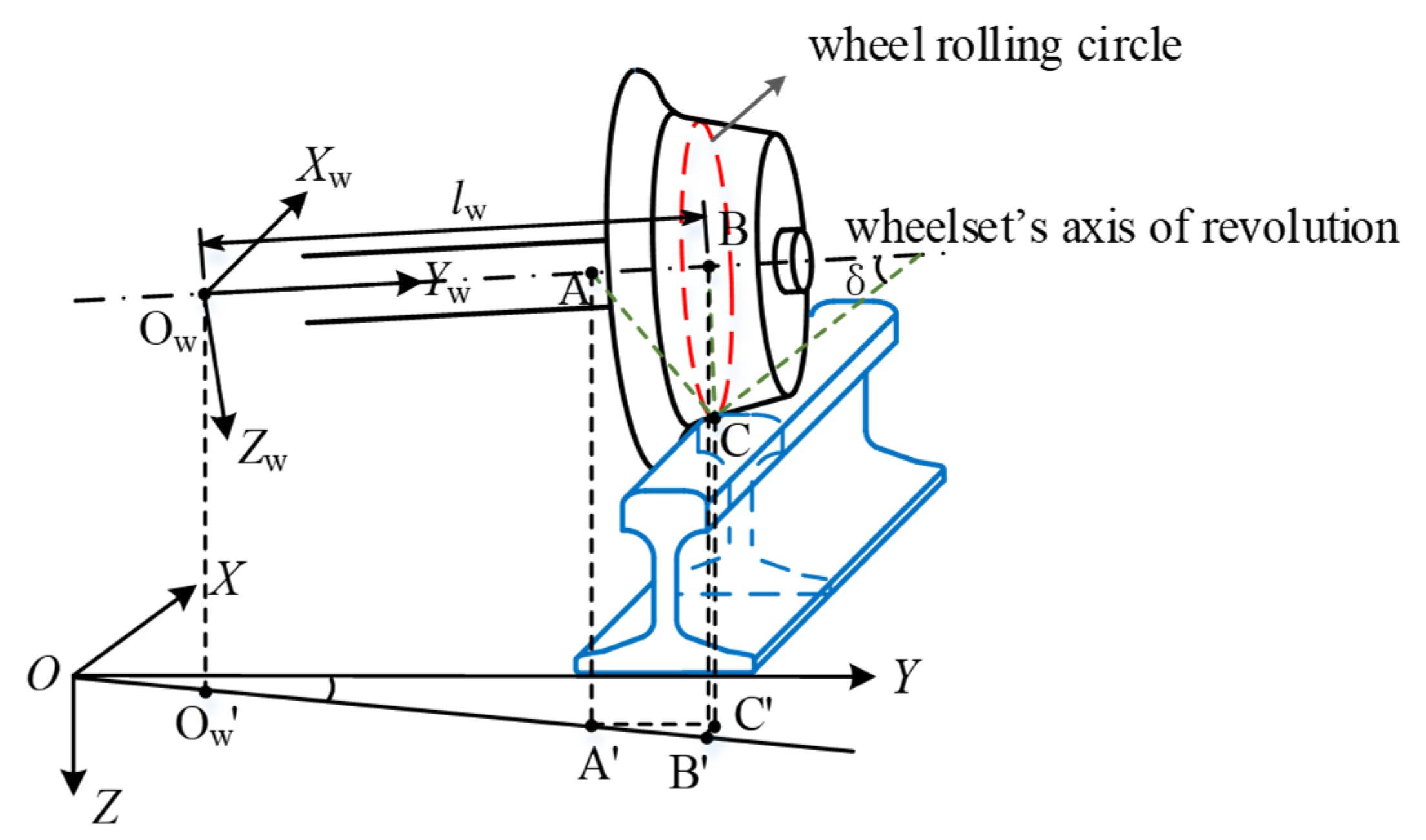
Figure 1. Calculation of wheel-rail contact geometric relationship.
Applsci 13 05230 g001
Figure 2. Determination of wheel-rail contact points and normal compression amounts based on different searching methods: (a) wheel-tread contact; (b) wheel-flange contact.
Applsci 13 05230 g002
Figure 3. Wheel-rail segment searching method.
Applsci 13 05230 g003
Figure 4. Distribution range of wheel-rail contact point positions in wheel-tread contact and flange contact.
Applsci 13 05230 g004
Figure 6. Train-track coupling system under earthquakes.
Applsci 13 05230 g006
Figure 7. Vehicle model with corresponding DOFs: (a) Side view; (b) Front view; (c) Top view; (d) Sign convention of vehicle.
Applsci 13 05230 g007
Figure 8. Diagram of CRTS II slab ballastless track (unit: m).
Applsci 13 05230 g008
Figure 9. Wheelset force state.
Applsci 13 05230 g009
Figure 10. Profiles of the wheel and rail (units: mm): (a) wheel profile; (b) rail profile.
Applsci 13 05230 g010
Figure 11. Samples of rail irregularities: (a) Lateral irregularities; (b) Vertical irregularities; (c) Torsional irregularities.
Applsci 13 05230 g011
Figure 12. Acceleration-time history of the ground motion.
Applsci 13 05230 g012
Figure 13. Time histories of wheel-rail dynamic responses based on different models: (a) Vertical wheel-rail force; (b) Lateral wheel-rail force; (c) Normal contact stiffness; (d) Normal compression amount.
Applsci 13 05230 g013
Figure 14. Time histories of wheel-rail contact forces based on Models 1 and 2: (a) Vertical wheel-rail force; (b) Lateral wheel-rail force.
Applsci 13 05230 g014
Figure 15. Wheel-rail contact state at time t = 3.80 s simulated based on Models 1 and 2: (a) Simulation result based on Model 1; (b) Simulation result based on Model 2.
Applsci 13 05230 g015
Figure 16. Time histories of wheel-rail dynamic responses based on Models 2 and 3: (a) Normal compression amount in region 1; (b) Normal compression amount in region 2; (c) Normal contact force in region 1; (d) Normal contact force in region 2; (e) Wheel jump amount.
Applsci 13 05230 g016
Figure 17. Time histories of wheel-rail dynamic responses based on Models 3 and 4: (a) Normal contact stiffness in region 1; (b) Normal contact stiffness in region 2; (c) Normal compression amount in region 1; (d) Normal compression amount in region 2; (e) Normal contact force in region 1; (f) Normal contact force in region 2.
Applsci 13 05230 g017
Figure 18. Maximum wheel-rail forces calculated based on different models: (a) Left vertical wheel-rail force; (b) Left lateral wheel-rail force; (c) Right vertical wheel-rail force; (d) Right lateral wheel-rail force.
Applsci 13 05230 g018
Figure 19. The vehicle dynamic analysis model established by Nishimura et al. [33]: (a) vehicle model; (b) track model.
Applsci 13 05230 g019
Figure 20. Time histories of wheel-rail contact force under excitation with frequency of 0.5 Hz and amplitude of 320 mm: (a) Vertical wheel-rail force; (b) Lateral wheel-rail force.
Applsci 13 05230 g020
Figure 21. Time histories of wheel-rail contact force under excitation with frequency of 0.8 Hz and amplitude of 105 mm: (a) Vertical wheel-rail force; (b) Lateral wheel-rail force.
Applsci 13 05230 g021
Figure 22. Time histories of wheel-rail contact force under excitation with frequency of 1.5 Hz and amplitude of 100 mm: (a) Vertical wheel-rail force; (b) Lateral wheel-rail force.
Applsci 13 05230 g022
Table 1. Setting of different wheel-rail contact models.
Wheel-Rail Contact ModelConsideration of Contact PointCalculation Basis for Normal Compression AmountAlgorithm for Normal Contact Stiffness
Model 1Single-point contactVertical penetrationEmpirical formula
Model 2Multipoint contactVertical penetrationEmpirical formula
Model 3Multipoint contactNormal penetrationEmpirical formula
Model 4Multipoint contactNormal penetrationTheoretical formula
Table 2. Limit values of train running safety indices.
Running Safety IndicesQ/P∆P/P∑Q (kN)
Limit0.80.855
Table 3. Maximum values of the running safety indices based on different models.
Running Safety IndicesModel 1Model 2Model 3Model 4
Q/P0.830.870.780.78
∆P/P0.951.00.800.79
∑Q (kN)228.79250.9949.3346.65
Disclaimer/Publisher’s Note: The statements, opinions and data contained in all publications are solely those of the individual author(s) and contributor(s) and not of MDPI and/or the editor(s). MDPI and/or the editor(s) disclaim responsibility for any injury to people or property resulting from any ideas, methods, instructions or products referred to in the content.