Article

Design and Investigation of a Novel Local Shielding Gas Concept for Laser Metal Deposition with Coaxial Wire Feeding

Technical University of Munich, TUM School of Engineering and Design, Department of Mechanical Engineering, Institute for Machine Tools and Industrial Management (iwb), Boltzmannstrasse 15, 85748 Garching, Germany
*
Author to whom correspondence should be addressed.
Appl. Sci. 2023, 13(8), 5121; https://doi.org/10.3390/app13085121
Submission received: 14 March 2023 / Revised: 15 April 2023 / Accepted: 18 April 2023 / Published: 20 April 2023

Abstract

:
Laser metal deposition with coaxial wire feeding is a directed energy deposition process in which a metal wire is fed to a laser-induced melt pool. Oxidation occurring during the process is a major challenge as it significantly influences the mechanical properties of the produced part. Therefore, an inert gas atmosphere is required in the high temperature process zone, whereby local shielding offers significant cost advantages over an inert gas chamber. In this work, a novel local shielding gas nozzle was developed based on basic methods of fluid mechanics. A gas flow-optimized prototype incorporating internal cooling channels was additively manufactured by laser-powder bed fusion and tested for its effectiveness via deposition experiments. Using the developed local shielding gas concept, an unwanted mixing with the atmosphere due to turbulence was avoided and an oxide-free deposition was achieved when processing a stainless steel ER316LSi wire. Furthermore, the effects of the shielding gas flow rate were investigated, where a negative correlation with the melt pool temperature as well as the weld bead width was demonstrated. Finally, a solid cuboid was successfully built up without oxide inclusions. Overheating of the nozzle due to reflected laser radiation could be avoided by the internal cooling system. The concept, which can be applied to most commercially available coaxial wire deposition heads, represents an important step for the economical application of laser metal deposition.

1. Introduction

Additive manufacturing of metal components is currently becoming increasingly relevant for a wide range of industrial applications. Directed energy deposition (DED) processes are an essential driver for this development [1]. In these processes, a feedstock material in the form of powder or wire is melted by an energy source and deposited onto a substrate in layer-by-layer mode [2]. This approach typically enables significantly higher build rates than the widely used powder-bed fusion processes. Laser radiation is one of the most economically relevant of the different energy sources used for DED processes, as it allows for precise control of the energy input into the workpiece. This typically results in low thermal stresses and distortion. The corresponding processes are referred to as laser metal deposition (LMD).
The use of wire as feedstock provides several advantages over the use of powder, such as low cost, good availability, ease of handling, and a low contamination of the process environment [3]. However, the wire is typically fed laterally to a solid laser beam, resulting in a strong directional dependence of the process. In order to overcome this directional dependence, laser processing heads that allow for coaxial wire feeding either in the center of several single beams [4,5,6] or inside an annular laser beam [7,8,9] are increasingly being utilized. A schematic representation of the process principle of laser metal deposition with coaxial wire feeding is illustrated in Figure 1.
With regard to the industrial application of LMD processes, the resulting material properties are of crucial importance. Oxidation, which can occur during the process above a specific temperature depending on the material deposited, affects these properties significantly [10,11]. In order to reduce the negative effects of oxidation, the concentration of oxygen in the high temperature process zone is typically decreased by displacing the atmospheric oxygen with inert gases, such as argon, nitrogen, or helium [12].
Regarding DED processes, numerous research papers exist on the effects of the atmospheric conditions on the resulting material properties. Besides the widely studied highly reactive materials (e.g., titanium alloys [13,14,15,16]), nickel-based alloys [12], stainless steels [17], and zirconium alloys [18] have also been investigated. The results of these studies indicate that a low concentration of oxygen in the process zone is required for favorable part properties. However, a certain amount of oxygen may be tolerable depending on the material used [17].
The choice of the shielding gas itself is another factor that has a significant influence on the deposition process. For DED processes as well as for metal welding processes, mainly argon and helium are utilized. With regard to the stability of the gas flow, argon is preferable due to its robustness against external disturbances as well as reduced diffusion of the atmosphere [19]. In addition, argon is considerably less expensive than helium, resulting in a significant economic advantage.
A common method for preventing atmospheric contamination during the process is to use a physical chamber filled with inert gas [20,21,22,23,24]. However, this method is highly cost-intensive due to the required equipment, the inert gas volume, and the time required for flooding the chamber [25]. In addition, the dimensions of the chamber limit the size of the components to be produced, modified, or repaired.
Another approach to create an inert gas atmosphere in the process zone is to use a local shielding gas device. For this, a sufficiently large local shielding gas environment needs to be created to prevent oxidation of the melt pool and the deposited material during cooling. If this is not ensured, the deposited material typically includes oxide contaminations. For wire-based DED processes, these contaminations manifest themselves mainly in oxide layers on the surface of the deposited weld beads. During the build-up of multi-layer parts, these oxide layers are remelted and become impurities within the deposited material, which deteriorate the mechanical properties [26]. In a previous study, this effect was observed for LMD with coaxial wire feeding of stainless steel due to an insufficient shielding gas coverage [27]. Nevertheless, in contrast to an inert gas chamber, local shielding allows for efficient and economical processing independent of the part size. The method used to generate a local inert gas atmosphere is highly dependent on the employed process as well as the specific application. In the design of local shielding gas devices, one main objective is to generate a stable laminar flow to avoid mixing of the inert gas flow with the atmosphere [19]. For the purpose of efficiently assessing the flow conditions, computational fluid dynamic (CFD) simulations are a commonly used tool.
Various local shielding gas concepts were established for wire and arc additive manufacturing (WAAM) [28,29,30,31,32]. The common approach is to use a trailing shielding device with a laminar flow in order to protect not only the melt pool, but also the deposited bead while at higher temperatures [26]. Similarly, Kelbassa pursued an approach for powder-based LMD in which the shielding gas device was adapted to the deposition geometry and additionally sealed with a flexible aluminum foil [26]. However, although these approaches are advantageous with respect to gas consumption, they are not suitable for arbitrary 3D applications with frequent changes in the processing direction. For this reason, an axisymmetric nozzle is required.
In powder-based LMD, the inert carrier gas used to feed the material to the melt pool also serves to generate a shielding gas atmosphere. However, the commercially available powder nozzles show limitations in terms of shielding the entire high-temperature zone. Therefore, some studies investigated a possible enlargement of the protected area by means of additional shielding gas nozzles for powder-based LMD, as described in the following.
Cortina et al. [33] used a cone-shaped shielding gas nozzle in addition to an existing powder nozzle [34] to increase the area covered by shielding gas. CFD simulations were performed to investigate the argon concentration in the process zone and the effects of the additional shielding gas flow on the powder flow. The additional nozzle led to a significant increase in the shielded area, enabling oxide-free weld beads to be deposited, whereas significant oxidation occurred with the original nozzle. More complex nozzle geometries were not considered and the deposition experiments were limited to single weld beads.
Li et al. [35] investigated the shielding gas coverage achieved with an additional local shielding gas nozzle for powder-based LMD of Ti-6Al-4V. They used a 3D CFD model to evaluate the influence of the number of inlets to the nozzle, the inlet angle, and the flow rate on the argon concentration in the process zone. In a further study, Li et al. [25] extended the area covered with inert gas by adding an additional external shielding nozzle coaxial to the one described in [35]. The shielding gas coverage on a flat substrate plate was investigated at different flow rates using CFD simulations. Based on the simulations, the process parameters were adjusted to achieve an oxide-free deposition of individual weld beads as well as small multi-layer geometries.
A similar concept was used by Nalam et al. [36], who added an additional coaxial inert gas nozzle to a commercial powder deposition nozzle. Internal lattice structures were included to improve the flow distribution inside the nozzle as well as the flow uniformity at the nozzle exit. To better understand the flow behavior of the gases, CFD simulations were employed. After the nozzle was additively manufactured by powder-bed fusion of metals using a laser beam (PBF-LB/M), small cubes of a Mo-Si-B alloy could be built without extensive oxidation.
Kolsch et al. [19] developed a dedicated shielding gas nozzle for the powder-based LMD of large structural space components made of titanium alloys. A honeycomb-like structure was applied in conjunction with a faster outer flow curtain to prevent turbulence in the shielding gas flow and, thus, mixing with the atmosphere. Cooling channels were introduced into the nozzle to counteract overheating due to reflected laser radiation. The complex nozzle design was realized by additive manufacturing through PBF-LB/M. Using this system, mostly oxide-free components made of Ti-6Al-4V with good mechanical properties could be produced.
In the existing studies, various shielding gas concepts for several DED processes were developed, and the effects of the shielding gas atmosphere on the process as well as on the resulting material properties were investigated. For LMD with coaxial wire feeding, depending on the system used, both off-axis [8,37,38] and simple coaxial [3,9,39,40,41,42] approaches exist for the local shielding gas supply. However, in contrast to powder-based LMD, no in-depth investigations have been carried out with regard to adapted nozzle geometries and the resulting shielding gas coverage. Since wire-based LMD lacks the carrier gas flow of the powder-based process variant and the geometric constraints due to the conical shape of the laser beam have to be taken into account, the nozzle concepts presented for powder-based LMD are not directly transferable.
Therefore, the objective of this work was to design a dedicated shielding gas nozzle for LMD with coaxial wire feeding and to investigate its performance thoroughly. So far, a similar concept has not been realized in the literature. For this purpose, a direction-independent shielding gas device was designed based on various methods of fluid mechanics and iteratively improved by means of 3D CFD simulations. Based on the flow studies, a prototype with additional integrated cooling channels was manufactured using PBF-LB/M. The shielding gas concept was validated based on deposition experiments. For individual weld beads, the influence of the shielding gas flow rate on the geometrical properties as well as the melt pool temperature was evaluated. Moreover, a defect-free multi-track multi-layer cuboid was built with close to no oxidation.

2. Development of a Local Shielding Gas Concept

2.1. Design and Process Requirements

Various requirements and constraints arising from the LMD process as well as the spatial conditions had to be considered regarding the nozzle design. First, a shielding gas supply coaxial to the laser beam and the wire was essential in order to assure a direction-independent process for arbitrary geometries. For this reason, it was also not possible to take advantage of a narrow outlet gap by adapting the nozzle to the part geometry, as it is frequently used in trailing gas shields for welding applications [19,43]. At the same time, the overall component had to be as narrow as possible for a good accessibility in a wide range of applications. For the local shielding gas device to be a viable alternative to an inert gas chamber, a sufficiently large area had to be covered to avoid unacceptable oxidation of the deposited material. The minimum area to be protected depends on the traverse speed as well as the cooling rate, and should generally be as large as possible. Regarding the design of the inner nozzle geometry, a laminar flow needed to be achieved to minimize mixing of the gas flow with the surrounding atmosphere due to turbulence. The design area was, thereby, limited by the conical laser beam. Simultaneously, a low shielding gas flow rate was desired with regard to an economical process. To prevent overheating due to laser radiation reflected from the process zone, the nozzle had to be manufactured from highly reflective materials and feature active cooling.

2.2. Computational Simulation Method

In order to obtain detailed insights into the performance of different approaches for the nozzle geometry, CFD simulations were carried out using the software ANSYS CFX 2021 (Ansys, Inc., Canonsburg, PA, USA). A 3D CFD model was utilized to investigate various arrangements of the shielding gas inlets as well as asymmetric variants of the nozzle outlet. For the numerical modeling of the turbulent flow, a shear-stress transport turbulence model was used. The fluids employed were argon for the shielding gas and air for the surrounding atmosphere. In the simulations, the gases were considered to be isothermal. Various design iterations were evaluated with regard to the given application. When comparing different nozzle geometries, uniform flow parameters were used. In all comparative cases, a shielding gas flow of 50 l/min was simulated over a flat 100 mm × 100 mm substrate plate with a stand-off distance of 10 mm to the nozzle outlet. The performance of the respective nozzle geometry was evaluated based on the transient behavior of the flow as well as the area on the substrate plate covered with inert gas (see Section 4.1). This procedure allowed a large number of nozzle geometries to be compared qualitatively without requiring them to be manufactured and tested at great expense. The concept that proved to be most suitable for the given application is presented in the following section.

2.3. Design of the Shielding Gas Nozzle Geometry

Due to the similar requirements, design guidelines for subsonic wind tunnels were incorporated in the final design of the shielding gas nozzle [44,45]. The shielding gas device was designed in two parts, which had both manufacturing and functional reasons (see Section 2.4). These two parts will be referred to as adapter and nozzle in the following. The inner contours of the adapter and the nozzle were designed as sequential contraction cones corresponding to those used in wind tunnels before the test section. According to Mehta and Bradshaw [46], a wind tunnel contraction leads to a uniform velocity profile across the outlet area and reduces the degree of turbulence of the flow. The most important parameter determining these properties is the contraction ratio σ, which is defined as the ratio of the nozzle inlet area to the nozzle outlet area [47]. It was shown that axial velocity differences in the flow profile are reduced to the same extent as the mean velocity increases due to the contraction effect [48]. However, for the given application, the contraction ratio must not be too high, as this would contradict the required shielding gas coverage over a large area. In addition, a high gas velocity could negatively affect the melt pool stability. Considering these aspects, contraction ratios between 5 and 7 were found to be a reasonable compromise.
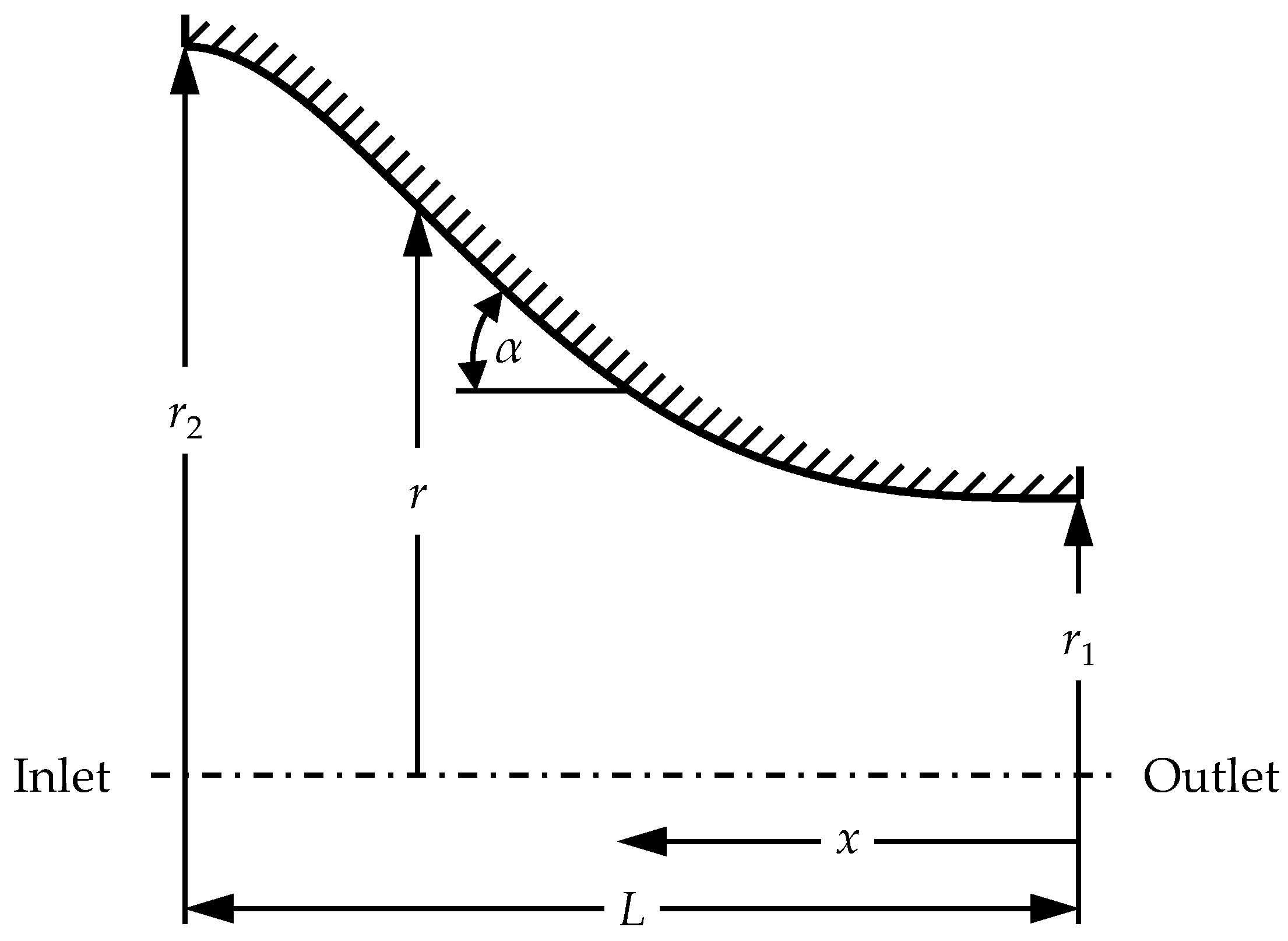
In addition to the contraction ratio, the contour of the contractions had to be determined. It is noteworthy that the exact shape of the contour has only a minor influence on the flow profile as long as basic requirements are met [46]. For describing the contour, various analytical approaches were proposed in the literature [47,49,50,51,52,53]. In this work, the contraction contour was designed according to Wille [54] and can be described by
r r 1 r 2 r 1 = ( x L ) 3 [ 2 ( x L ) 3 ] ,  
where r is the radius at a distance x from the nozzle outlet; r2 and r1 refer to the inlet and outlet radius, respectively; and L is the length of the contraction. Thereby, the maximum wall angle to the axis α should satisfy the condition αmax ≤ 43° [55]. The contour is illustrated in Figure 2 together with the relevant parameters.
Considering the given requirements and spatial constraints, the parameters listed in Table 1 were chosen to describe the contours of the two sequential contractions. One appealing feature of the selected contour is that it resembles the tapered shape of the conical laser beam, thus enabling a highly compact design. It should be noted that, because the inert gas needs to be fed into the adapter from the side, there is no continuous flow profile over the entire cross-section at the adapter inlet. However, this approach yielded satisfactory results in the simulation regarding the uniformity of the flow profile at the inlet of the nozzle.
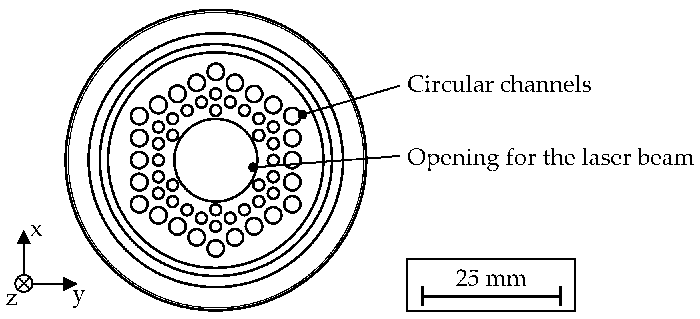
In order to extend the area covered by the shielding gas without introducing turbulence, a flow straightener in the form of circular channels [45] was added to the nozzle, superimposed on the contraction cone. This provides an additional laminar outer flow curtain, which protects the center region from atmospheric diffusion. For this purpose, additional holes were inserted into the nozzle. The arrangement as illustrated in Figure 3, consisting of 54 holes with diameters of 2 mm and 3 mm, resulted in a significant improvement of the shielding gas coverage, while at the same time a robust design and good manufacturability were ensured. Since a honeycomb-like structure did not improve the flow condition beyond this, it was not considered further. Overall, the chosen design resulted in a laminar shielding gas flow at the nozzle outlet with virtually no radial velocity component.
Moreover, different variations for the shielding gas inlets into the adapter were evaluated regarding the number of inlets and the angle. The most uniform flow conditions were obtained with a configuration of five evenly distributed inlets at an angle of 75° to the vertical axis (see Figure 4).

2.4. Implementation of the Shielding Gas Concept

In addition to the design of the inner nozzle geometry with regard to laminar flow conditions, further requirements had to be addressed to employ the shielding gas device in the demanding environment of the LMD process (see Section 2.1). Figure 4 shows the final design of the entire assembly as a sectional view.
During the deposition process, both the thermal radiation emitted from the process zone as well as the laser radiation that is partially reflected at the melt pool cause the nozzle to heat up. This is especially relevant for the continuous deposition of large parts or coatings. For this reason, the nozzle was machined from brass (CuZn39Pb3), which exhibits a low absorption coefficient at infrared wavelengths as well as an excellent thermal conductivity. The nozzle was attached to the adapter via an M44 fine thread. Moreover, an additional thread was included at the end of the nozzle, enabling additional features for specialized applications, such as a trailing nozzle, to be attached.
In order to protect the sensitive optical components of the wire deposition head from overheating due to heat conduction, water cooling was integrated into the adapter. Additional pins were introduced into the cooling channel, which improved the heat transfer by increasing the wetted surface as well as the turbulence in the cooling water flow [56]. The inlet of the shielding gas was implemented using a single central connection in conjunction with an internal distribution to the five inlets of the adapter. To ensure uniform flow conditions at the five inlets, the internal channels were designed to be of equal length.
The complex internal geometry of the part was realized by manufacturing using PBF-LB/M, whereby the limitations of conventional manufacturing processes could be circumvented. As material, the aluminum alloy AlSi10Mg was employed. It is worth mentioning that the realized design represents a perfect example for the possibilities of additive manufacturing, whereas the part could not have been produced in this form using traditional manufacturing methods.
Figure 4. Cross-sectional view showing the final computer-aided design model of the shielding gas device with the various design features.
Applsci 13 05121 g004

3. Experimental Procedures

3.1. Materials

In the experimental investigations, stainless steel alloys were used. With these, the level of oxidation could be initially classified by visual inspection based on annealing colors or a dark oxide layer, respectively. An austenitic stainless steel ER316LSi wire with a diameter of 1 mm was employed as feedstock material. The wire was deposited on plates of stainless steel AISI 304 with dimensions of 100 mm × 100 mm × 10 mm. Before each experiment, the plates were cleaned with isopropanol to remove existing contaminants. Table 2 shows the chemical compositions of the materials used. For all tests conducted, high purity argon (grade 5.0) was used as the shielding gas.

3.2. Experimental Setup

A coaxial wire deposition head (CoaxPrinter, Precitec GmbH & Co. KG, Gaggenau, Germany) was the core of the experimental setup. This enabled coaxial feeding of the wire inside an annular laser beam profile, leading to a direction-independent LMD process. For the generation of the laser radiation with a wavelength of 1030 nm, a 4 kW disk laser (TruDisk 4001, TRUMPF GmbH & Co. KG, Ditzingen, Germany) operating in continuous wave mode was employed. The radiation was transmitted to the wire deposition head by a fiber optic cable with a core diameter of 600 µm.
Through an industrial wire feeding system from the manufacturer DINSE GmbH (Hamburg, Germany), a defined feed rate of the wire was ensured. The wire feeding was realized through a front drive (FD100 LS) and a slave drive (WD 300 FD), which operated in push–pull mode, and were actuated by a control unit (FDE-PN 100 L). As the wire was delivered in a 15 kg coil, its curvature was compensated for by a precisely adjusted two-plane wire straightening unit. A six-axis industrial robot (KR 60 HA, KUKA AG, Augsburg, Germany) with a maximum payload of 60 kg was used for an accurate positioning of the wire deposition head. The robot was actuated by a robotic control system (KR C4, KUKA AG, Augsburg, Germany). To coaxially measure the melt pool temperature during the process, a pyrometer (METIS M322, Sensortherm GmbH, Steinbach, Germany) in one-color mode (sensitive in the range of 1.45–1.65 µm) with a temperature measurement range of 600–2300 °C was mounted to the wire deposition head. The pyrometer was calibrated to the surface temperature of the melt pool following the procedure described by Zapata et al. [57].
In wire-based LMD, it is still common to use a lateral shielding gas supply through a thin tube for many materials and applications [58,59]. This also applies to previous works on the employed wire deposition head [8,27,37]. Therefore, this configuration was additionally considered as a reference. In the following, the configurations will be referred to as lateral nozzle and optimized nozzle. The respective experimental setups are depicted in Figure 5. In the lateral configuration, the shielding gas was supplied via a copper tube with an inner diameter of 4 mm (see Figure 5a). The system equipped with the optimized nozzle is shown in Figure 5b. To attach the assembly to the wire deposition head, the existing mounting ring for accessory parts was used.

3.3. Experimental Procedure

To evaluate the performance of the shielding gas nozzles, deposition experiments were carried out. The focal position was set at −6 mm (below the surface of the substrate) corresponding to a stand-off distance between the wire nozzle and the substrate of 10 mm. Individual weld beads with a length of 85 mm were deposited on the substrate plates, with the shielding gas flow rate being varied in steps of 10 l/min. The process parameters were chosen based on previous investigations by Zapata et al. [60] and are listed in Table 3.
Furthermore, a solid cuboid with a base area of 15 mm × 15 mm and a height of approximately 4.8 mm was built up using the optimized shielding gas nozzle. The respective process parameters are also given in Table 3. A meandering deposition pattern with laterally overlapping weld beads was applied in each layer and the orientation of the layers was rotated by 90° in an alternating manner. Based on a preliminary work [27], the distance between adjacent tracks was set at 1.1 mm in order to obtain a surface with minimum waviness. The height increment after each layer was 0.79 mm.

3.4. Characterizations

To investigate the effect of the shielding gas flow on the resulting weld bead geometry, the individual weld beads were scanned using a 3D profilometer (VR-3100, Keyence Corporation, Osaka, Japan). The geometry was evaluated at ten positions along each of the weld beads. Existing thermal distortions of the substrate plates resulting from the process were compensated for by using the software provided by the manufacturer. For the metallographic analysis of the deposited cuboid, a cross-section through the center of the specimen was taken. The sample was ground in four steps (180, 300, 800, 1200 grit) and then polished (3 μm, 1 μm). To analyze the microstructures, the sample was treated with an etching solution (Adler) by immersion technique and examined with a digital microscope (VHX-7000, Keyence Corporation, Osaka, Japan). A scanning electron microscope (JSM-IT200, JEOL Ltd., Akishima, Japan) with an integrated unit for energy dispersive X-ray spectroscopy (EDS) was utilized to investigate the oxygen distribution in the built-up cuboid. The accelerating voltage applied was 20 kV. This investigation was carried out before treating the sample with the etching solution.
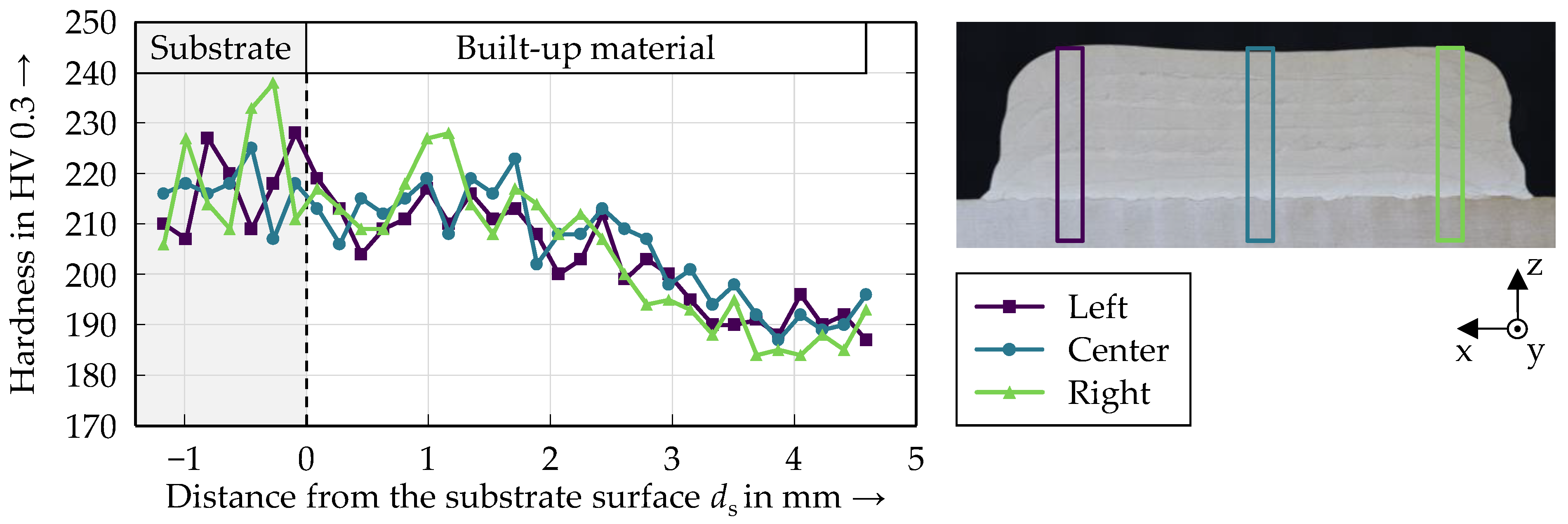
Vickers microhardness measurements according to DIN EN ISO 6507-1 were performed on the cross-section of the built-up cuboid using a fully automated hardness tester (Qness 60 A+ EVO, ATM Qness GmbH, Mammelzen, Germany). For each indentation, a test force of 2.942 N (corresponding to HV 0.3) was applied for a dwell time of 10 s. The hardness was evaluated at 33 positions along three straight lines from the bottom to the top of the cuboid. For each line, the distance between the center points of adjacent indentations was 180 µm.

4. Results and Discussion

4.1. Simulative Evaluation of the Shielding Gas Coverage

First, the oxygen distribution when using the optimized nozzle was analyzed based on simulations. Figure 6a shows the contour plot of the oxygen distribution in the process zone at a shielding gas flow rate of 50 l/min. The oxygen concentrations in parts per million (ppm) were calculated from the mass fractions obtained in the simulation. Directly below the nozzle outlet, a cylindrical free jet region is formed. In this area, no turbulent flow and, thus, no unacceptable mixing with the surrounding atmosphere is apparent. Once the free jet reaches the substrate plane, it propagates along the surface and forms a laminar zone. Towards the outer edges of the substrate, gradual mixing with the atmosphere occurs, resulting in a decreasing thickness of the shielding gas layer. The flow above the hot process zone also serves as a convection cooling, which could have a positive effect with regard to a higher cooling rate. In addition, a map of the oxygen concentration on the substrate plane is displayed in Figure 6b.
In order to reliably avoid unacceptable oxidation during the process, the dimensions of the area sufficiently covered with shielding gas are relevant. This area is referred to as the “effective protective region” [25]. For the processing of titanium in DED processes, the effective protection region was defined by Ding et al. [28] as well as Li et al. [25] as the area in which the oxygen concentration was below 2000 ppm. Although stainless steel is less critical than titanium in terms of the maximum acceptable oxygen concentration, this value was used as a conservative limit in the simulations. The effective protection region is indicated in Figure 6b. To evaluate the shielding effect based on CFD simulations, the flow rate was varied between 5 l/min and 100 l/min in steps of 5 l/min. To quantify the shielding effect, the average diameter of the effective protection region on the substrate plane was determined for each flow rate. This diameter is referred to as the “effective protection length” [25]. Figure 7 shows the effective protection length as a function of the flow rate. A distinct trend is visible, where a higher flow rate results in a larger protected area. Between 5 l/min and 40 l/min, the effective protection length increases rapidly from 0 mm to 65.9 mm. In contrast, a further increase of the flow rate from 40 l/min to 100 l/min results in only a 2.7% increase of the effective protection length.
In this study, only the fundamental case when depositing on a flat substrate was considered. It is noteworthy that the protected area is smaller when larger components with arbitrary geometries are built. The volumetric area with a sufficiently low oxygen concentration strongly depends on the respective component geometry below the nozzle outlet. In the case of a thin wall, it can be assumed that at least the cylindrical free jet region with a diameter of approximately 28 mm is sufficiently covered with shielding gas [19]. In order to minimize oxidation, it is therefore crucial that the hot process zone cools down rapidly enough while still covered by shielding gas. The main influencing factors for this are the heat dissipation in the component and the traverse speed.

4.2. Deposition of Single Weld Beads

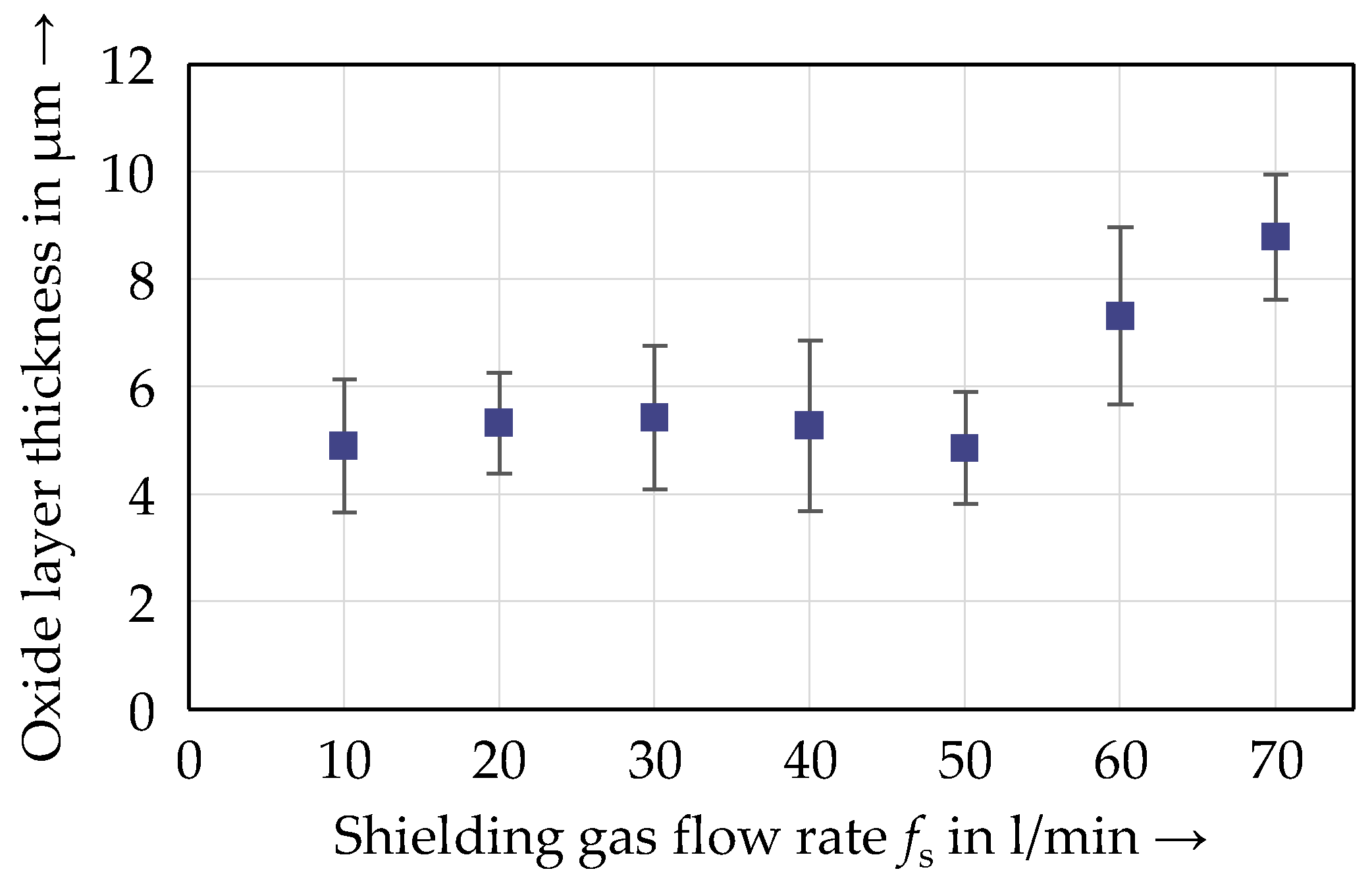
In order to compare the effectiveness of the optimized shielding gas nozzle and the lateral nozzle, individual weld beads were deposited using both configurations. In each case, the shielding gas flow rate was systematically varied in steps of 10 l/min from 10 l/min to 70 l/min, corresponding to the maximum possible output of the system used. Figure 8 shows sections of the various weld bead surfaces. Using the lateral nozzle, a strong oxidation in the form of a dark oxide layer on the weld beads is evident at flow rates ranging from 10 l/min to 60 l/min (see Figure 8a). At a flow rate of 70 l/min, no stable melt pool could be formed and the melt was blown to the side in droplets, preventing the deposition of a continuous weld bead. With this lateral configuration, despite the high cooling rate when depositing a single bead directly on the substrate plate, the covered area was not sufficiently large to avoid strong oxidation. Apparently, for the continuous weld beads, the degree of oxidation even increased with an increasing flow rate. This could be confirmed through measurements in cross-sections of the weld beads, in which the mean thickness of the oxide layer increased from approximately 4.9 µm at 10 l/min to 8.8 µm at 60 l/min (see Appendix A). This observation can be explained by a more turbulent flow at higher velocities. Due to the small nozzle diameter, a high flow velocity occurs at comparatively low volume rates, which causes high Reynolds numbers. The critical Reynolds number for the outflow of a free jet is in the range of 1500–2300, above which the flow transitions into turbulence [19]. This turbulence causes increased mixing with the atmosphere, which was also demonstrated by Fonte et al. [61] and Teng et al. [62]. Thus, at higher flow rates, the amount of atmospheric oxygen within the process zone was significantly larger.
In contrast, the weld beads produced using the optimized shielding gas nozzle exhibited a completely bright surface (see Figure 8b). For a shielding gas flow of 10 l/min, slight discolorations could be observed, while for the other experiments no discolorations were visible. Since the formation of discolorations is an indicator for the presence of residual oxygen in the welding atmosphere, a complete protection of the hot process zone can be assumed for shielding gas flow rates ranging from 20 l/min to 70 l/min regarding the given setup. It is noteworthy that higher flow rates apparently did not result in significant turbulence and, thus, mixing with the atmosphere due to the nozzle being designed for a laminar flow. Remarkably, for smaller flow rates, ripples in the weld beads could be observed. According to Arbo et al. [58], such ripples occur at high heat inputs, where an incipient dripping of the wire leads to a discontinuous deposition. In the present case, this is related to the decreased cooling effect at low shielding gas flows. The correlation between the shielding gas flow rate and the melt pool temperature is analyzed in the following section.

4.3. Influence of the Shielding Gas Flow Rate on the Weld Bead Geometry and the Melt Pool Temperature

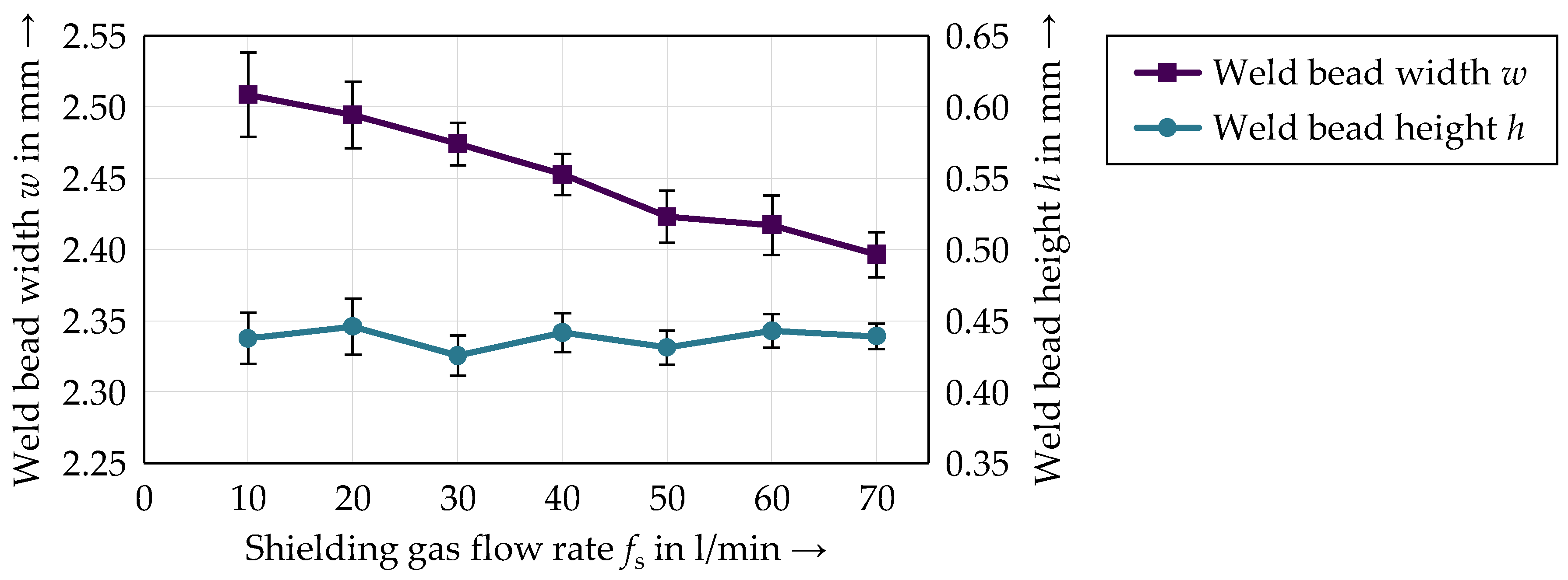
For the build-up of defect-free and geometrically accurate components, precise knowledge about the dependence of the weld bead geometry on the input parameters of the process is essential. Therefore, the influence of the shielding gas flow rate on the geometry of the weld beads was examined. In these further investigations, only the optimized shielding gas nozzle was employed. In Figure 9, the weld bead width and height are plotted as a function of the flow rate. The weld bead width exhibited a descending trend with increasing flow rates. This can be attributed to the increased cooling of the melt pool due to convection. For a constant focal distance, a lower melt pool temperature is typically associated with a lower expansion of the melt pool and a higher surface tension [63]. In contrast, no distinct correlation between the flow rate and the weld bead height was evident. An influence of the increasing gas pressure above the surface, which is expected at higher flow rates and could result in a flattening and widening of the melt pool, was not observed for the parameter range investigated. Therefore, the cooling effect of the shielding gas flow is assumed to be the dominant influencing factor for the resulting weld bead geometry.
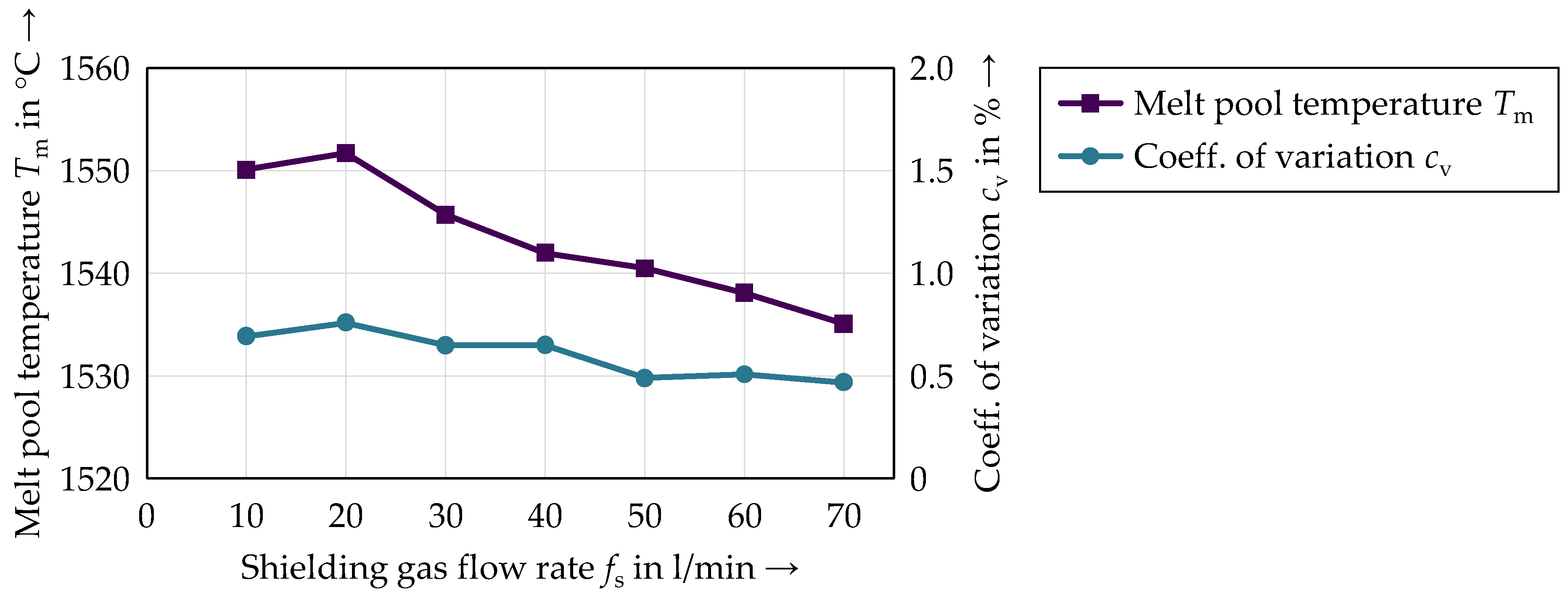
In order to confirm the cooling effect of the shielding gas flow, the melt pool temperature was monitored during the process using an in-axis pyrometer. The temperature data of the first 25 mm and the last 8 mm of the weld beads were omitted, so that only the stationary phase of the process was considered [64]. In Figure 10, the average melt pool temperatures during the stationary phase of the process are shown as a function of the flow rate. The absolute difference between the maximum and the minimum average temperature was approximately 15 K. It is worth noting that a closed-loop control system could be employed to compensate for the temperature deviations of the melt pool induced by the different shielding gas flow rates [65].
To quantify the existing fluctuations in the temperature signals, the coefficient of variation cv, i.e., the ratio of the standard deviation to the mean value, was calculated (see Figure 10). At higher flow rates, the fluctuations in the temperature signals tended to decrease, indicating a less dynamic melt pool. This was also reflected in the reduced appearance of ripples in the weld beads, which were described above. Therefore, with regard to an economical process, a large covered area and the prevention of ripples in the weld beads, a shielding gas flow rate of 40 l/min appears to be a suitable value for the given setup.

4.4. Build-Up and Characterization of a Solid Cuboid

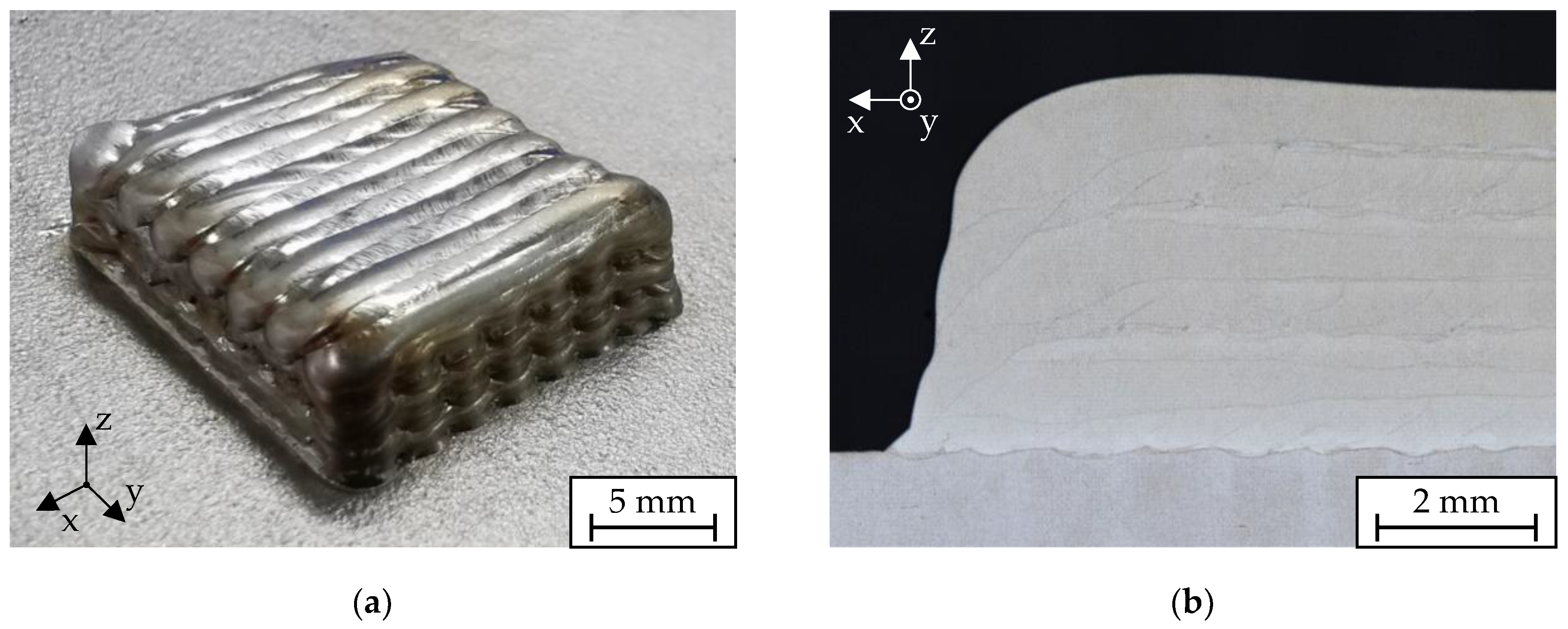
To further evaluate the effectiveness of the shielding gas concept, a solid cuboid was built up applying a shielding gas flow rate of 40 l/min, as shown in Figure 11a. The outer surface exhibited a bright metallic finish, with only marginal discolorations visible on the side walls. Figure 11b shows a cross-section of the deposited cuboid. No oxide inclusions could be observed in the cross-section, as they would typically occur with an insufficient shielding gas coverage using a conventional lateral nozzle [27]. This demonstrates that no unacceptable oxide layers were formed even under the high thermal load during the build-up of a solid component.
In the cross-section of the built-up cuboid, a semi-quantitative chemical analysis of the oxygen content was performed using EDS. For this purpose, a line scan was performed over the entire height, as illustrated in Figure 12. The detected oxygen content varied only slightly over the entire length of the scan. In particular, there was no significant difference in the oxygen content between the substrate material and the deposited material. Furthermore, no pronounced peaks could be identified, which would indicate oxide inclusions in the material. It is worth mentioning that the measurement procedure is not necessarily suitable for an absolute quantification. Still, the measurement indicates that possible process-related changes in the oxygen content were negligible.
The results of the Vickers microhardness measurements are shown in Figure 13. The hardness values measured varied in the range between 184 HV and 238 HV. For all three measurement locations, a significant trend of decreasing hardness values with an increasing build height could be observed. This decrease in hardness is characteristic for DED processes and can be explained by the lower cooling rates in higher layers and the corresponding slower velocities of solidification [66]. Between the three measurement locations, no significant differences in the microhardness distribution were apparent, indicating the deposition of homogeneous layers. In summary, it can be concluded that a high-quality solid cuboid without defects or unacceptable oxidation was successfully built up.

5. Conclusions

In laser metal deposition processes, oxidation is a major challenge, as it negatively affects the resulting mechanical properties of the built-up components. To reduce oxidation, either a complete inert gas atmosphere can be used or only the hot process zone can be shielded locally, with the latter approach offering considerable advantages in terms of gas consumption, equipment complexity, and setup time. The nozzle concepts studied in the literature are for powder-based LMD and cannot be directly applied to the wire-based process due to the lack of the carrier gas flow. In addition, geometric constraints resulting from the conical shape of the laser beam have to be considered. Therefore, in this work, a novel local shielding gas concept for laser metal deposition with coaxial wire feeding was developed and evaluated thoroughly for its effectiveness. First, a nozzle geometry was designed based on established concepts from fluid mechanics. For this, an iterative approach utilizing CFD simulations was pursued. For the final design, the flow rate was varied simulatively to obtain a sufficiently protected area at an economical gas consumption. Subsequently, the concept was investigated based on deposition experiments with stainless steel. The effects of the flow rate on the weld bead geometry as well as the melt pool temperature were examined. Finally, a fully dense solid cuboid without existing oxide inclusions was successfully built up. The following conclusions are drawn:
  • Using the developed shielding gas concept, an oxide-free deposition was possible for individual weld beads as well as for a solid cuboid.
  • The nozzle geometry enables a direction-independent shielding gas coverage with minimal turbulence, thus preventing mixing with the atmosphere.
  • Increasing the shielding gas flow rate from 10 l/min to 70 l/min resulted in a 15 K lower melt pool temperature as well as a drop in the weld bead width by approximately 110 µm. This could be attributed to the convective cooling effect of the shielding gas.
  • The concept is applicable to many commercially available coaxial wire deposition heads.
In the investigations conducted, the shielding gas concept proved to be highly effective for the deposition of stainless steel. In future studies, the application of the concept for the deposition of further materials, in particular, highly reactive alloys, should be investigated. Since oxidation is highly influenced by the cooling rate of the deposited weld bead as well as the traverse speed when using a local shielding gas concept, these factors should be additionally considered. Furthermore, it should be analyzed to which extent more complex part geometries affect the flow condition and, thus, the effective protection region. Another subject worth investigating is the effect of the shielding gas flow on the surface tension-based Marangoni flow within the melt pool and the resulting weld bead characteristics.

Author Contributions

Conceptualization, C.B.; Methodology, C.B., L.M. and A.Z.; Software, L.M.; Validation, C.B. and L.M.; Formal analysis, C.B. and X.F.Z.; Investigation, C.B. and L.M.; Resources, M.F.Z.; Data curation, C.B. and L.M.; Writing—original draft, C.B.; Writing—review & editing, A.Z., X.F.Z., S.B. and M.F.Z.; Visualization, C.B. and L.M.; Supervision, M.F.Z.; Project administration, C.B., X.F.Z. and M.F.Z.; Funding acquisition, C.B., X.F.Z. and M.F.Z. All authors have read and agreed to the published version of the manuscript.

Funding

The results presented were achieved within the AdDEDValue project, which is supported by the German Federal Ministry for Economic Affairs and Climate Action (BMWK) within the funding program “Digitalization of Vehicle Manufacturers and the Supplier Industry” (grant number 13IK002L) and supervised by the VDI Technology Center (VDI TZ). We would like to thank the BMWK and the VDI TZ for their support and for their effective and trusting cooperation.

Institutional Review Board Statement

Not applicable.

Informed Consent Statement

Not applicable.

Data Availability Statement

Not applicable.

Acknowledgments

This study was carried out using systems provided by the Precitec GmbH & Co. KG, the Sensortherm GmbH, and the DINSE GmbH. We thank our partners for entrusting us with the systems as well as the great cooperation.

Conflicts of Interest

The authors declare no conflict of interest.

Appendix A

Figure A1. Measured oxide layer thicknesses of the individual weld beads deposited using the lateral shielding gas nozzle; for each shielding gas flow rate, the average of twelve measurements distributed over the weld bead cross-section was determined.
Applsci 13 05121 g0a1

References

  1. Dass, A.; Moridi, A. State of the art in directed energy deposition: From additive manufacturing to materials design. Coatings 2019, 9, 418. [Google Scholar] [CrossRef]
  2. Svetlizky, D.; Das, M.; Zheng, B.; Vyatskikh, A.L.; Bose, S.; Bandyopadhyay, A.; Schoenung, J.M.; Lavernia, E.J.; Eliaz, N. Directed energy deposition (DED) additive manufacturing: Physical characteristics, defects, challenges and applications. Mater. Today 2021, 49, 271–295. [Google Scholar] [CrossRef]
  3. Kelbassa, J.; Gasser, A.; Bremer, J.; Pütsch, O.; Poprawe, R.; Henrich Schleifenbaum, J. Equipment and process windows for laser metal deposition with coaxial wire feeding. J. Laser Appl. 2019, 31, 022320-1–022320-7. [Google Scholar] [CrossRef]
  4. Silze, F.; Schnick, M.; Sizova, I.; Bambach, M. Laser metal deposition of Ti-6Al-4V with a direct diode laser set-up and coaxial material feed. Procedia Manuf. 2020, 47, 1154–1158. [Google Scholar] [CrossRef]
  5. Lammers, M.; Biester, K.; Schwarz, N.; Hermsdorf, J.; Kaierle, S.; Ahlers, H. Automatic changing of weld deposit for additive manufacturing of hybrid metal-glass components using direct laser deposition. In Proceedings of the Lasers in Manufacturing Conference 2021, Virtual Conference, 21–24 June 2021. [Google Scholar]
  6. Madarieta-Churruca, M.; Pujana-Astarloa, J.; Garmendia Saez-de-Heredia, I.; Leunda-Arrizabalaga, J. Additive manufacturing of metal components using concentric-wire laser metal deposition. DYNAII 2018, 93, 675–680. [Google Scholar] [CrossRef]
  7. Kelbassa, J.; Pütsch, O.; Gasser, A.; Biber, A.; Wissenbach, K.; Loosten, P.; Schleifenbaum, J.H. Influence of focal length on the laser metal deposition process with coaxial wire feeding. In Proceedings of the SPIE LASE, San Francisco, CA, USA, 2–7 February 2019; p. 11. [Google Scholar] [CrossRef]
  8. Motta, M.; Demir, A.G.; Previtali, B. High-speed imaging and process characterization of coaxial laser metal wire deposition. Addit. Manuf. 2018, 22, 497–507. [Google Scholar] [CrossRef]
  9. Govekar, E.; Jeromen, A.; Kuznetsov, A.; Kotar, M.; Kondo, M. Annular laser beam based direct metal deposition. Procedia CIRP 2018, 74, 222–227. [Google Scholar] [CrossRef]
  10. Milewski, J.O. Additive Manufacturing of Metals: From Fundamental Technology to Rocket Nozzles, Medical Implants, and Custom Jewelry, 1st ed.; Springer International Publishing: Cham, Switzerland, 2017; ISBN 978-3-319-58205-4. [Google Scholar]
  11. Saboori, A.; Piscopo, G.; Lai, M.; Salmi, A.; Biamino, S. An investigation on the effect of deposition pattern on the microstructure, mechanical properties and residual stress of 316L produced by Directed Energy Deposition. Mater. Sci. Eng. A Struct. Mater. 2020, 780, 139179. [Google Scholar] [CrossRef]
  12. Ruiz, J.E.; Cortina, M.; Arrizubieta, J.I.; Lamikiz, A. Study of the influence of shielding gases on laser metal deposition of Inconel 718 superalloy. Materials 2018, 11, 1388. [Google Scholar] [CrossRef]
  13. Cheng, D.; Zhang, J.; Shi, T.; Li, G.; Shi, J.; Lu, L.; Fu, G. Microstructure and mechanical properties of additive manufactured Ti-6Al-4V components by annular laser metal deposition in a semi-open environment. Opt. Laser Technol. 2021, 135, 106640. [Google Scholar] [CrossRef]
  14. Carrozza, A.; Aversa, A.; Mazzucato, F.; Lombardi, M.; Biamino, S.; Valente, A.; Fino, P. An innovative approach on directed energy deposition optimization: A study of the process environment’s influence on the quality of Ti-6Al-4V samples. Appl. Sci. 2020, 10, 4212. [Google Scholar] [CrossRef]
  15. Iantaffi, C.; Leung, C.L.A.; Chen, Y.; Guan, S.; Atwood, R.C.; Lertthanasarn, J.; Pham, M.-S.; Meisnar, M.; Rohr, T.; Lee, P.D. Oxidation induced mechanisms during directed energy deposition additive manufactured titanium alloy builds. Manuf. Lett. 2021, 1, 100022. [Google Scholar] [CrossRef]
  16. Klocke, F.; Arntz, K.; Klingbeil, N.; Schulz, M. Wire-based laser metal deposition for additive manufacturing of TiAl6V4: Basic investigations of microstructure and mechanical properties from build up parts. In Proceedings of the SPIE LASE, San Francisco, CA, USA, 28 January 2017. [Google Scholar]
  17. Valiente Bermejo, M.A.; Thalavai Pandian, K.; Axelsson, B.; Harati, E.; Kisielewicz, A.; Karlsson, L. Microstructure of laser metal deposited duplex stainless steel: Influence of shielding gas and heat treatment. Weld. World 2020, 65, 525–541. [Google Scholar] [CrossRef]
  18. Harooni, A.; Nasiri, A.M.; Gerlich, A.P.; Khajepour, A.; Khalifa, A.; King, J.M. Processing window development for laser cladding of zirconium on zirconium alloy. J. Mater. Process. Technol. 2016, 230, 263–271. [Google Scholar] [CrossRef]
  19. Kolsch, N.; Seidel, A.; Finaske, T.; Brueckner, F.; Gumpinger, J.; Bavdaz, M.; Rohr, T.; Ghidini, T.; Leyens, C. Novel local shielding approach for the laser welding based additive manufacturing of large structural space components from titanium. J. Laser Appl. 2020, 32, 22075. [Google Scholar] [CrossRef]
  20. Arcella, F.G.; Froes, F.H. Producing titanium aerospace components from powder using laser forming. JOM 2000, 52, 28–30. [Google Scholar] [CrossRef]
  21. Baier, D.; Bachmann, A.; Zaeh, M.F. Towards wire and arc additive manufacturing of high-quality parts. Procedia CIRP 2020, 95, 54–59. [Google Scholar] [CrossRef]
  22. Vaamonde, E.; Reya, P.; Ariasa, R.M.; Troncosoa, I. Effect of atmosphere conditions on additive manufacturing of Ti4Al6V by coaxial W-DED-LB process. In Proceedings of the Lasers in Manufacturing Conference 2021, Virtual Conference, 21–24 June 2021. [Google Scholar]
  23. Kisielewicz, A.; Thalavai Pandian, K.; Sthen, D.; Hagqvist, P.; Valiente Bermejo, M.A.; Sikström, F.; Ancona, A. Hot-wire laser-directed energy deposition: Process characteristics and benefits of resistive pre-heating of the feedstock wire. Metals 2021, 11, 634. [Google Scholar] [CrossRef]
  24. Veiga, F.; Gil Del Val, A.; Suárez, A.; Alonso, U. Analysis of the machining process of Titanium Ti6Al-4V parts manufactured by wire arc additive manufacturing (WAAM). Materials 2020, 13, 766. [Google Scholar] [CrossRef]
  25. Li, G.; Zhang, J.; Shi, T.; Shi, J.; Cheng, D.; Lu, L.; Shi, S. Experimental investigation on laser metal deposition of Ti-6Al-4V alloy with coaxial local shielding gas nozzle. J. Mater. Eng. Perform. 2020, 29, 7821–7829. [Google Scholar] [CrossRef]
  26. Kelbassa, I. Qualifizieren des Laserstrahl-Auftragschweißens von BLISKs aus Nickel- und Titanbasislegierungen; Fraunhofer Institute for Laser Technology: Aachen, Germany, 2006. [Google Scholar]
  27. Bernauer, C.; Merk, T.; Zapata, A.; Zaeh, M.F. Laser metal deposition with coaxial wire feeding for the automated and reliable build-up of solid metal parts. Key Eng. Mater. 2022, 926, 65–79. [Google Scholar] [CrossRef]
  28. Ding, J.; Colegrove, P.; Martina, F.; Williams, S.; Wiktorowicz, R.; Palt, M.R. Development of a laminar flow local shielding device for wire + arc additive manufacture. J. Mater. Process. Technol. 2015, 226, 99–105. [Google Scholar] [CrossRef]
  29. Miyake, R.; Sasahara, H.; Suzuki, A.; Ouchi, S. Wire arc additive and high-temperature subtractive manufacturing of Ti-6Al-4V. Appl. Sci. 2021, 11, 9521. [Google Scholar] [CrossRef]
  30. Bermingham, M.J.; Thomson-Larkins, J.; St John, D.H.; Dargusch, M.S. Sensitivity of Ti-6Al-4V components to oxidation during out of chamber wire + arc additive manufacturing. J. Mater. Process. Technol. 2018, 258, 29–37. [Google Scholar] [CrossRef]
  31. Karpagaraj, A.; Siva Shanmugam, N.; Sankaranarayanasamy, K. Experimental investigations and numerical prediction on the effect of shielding area and post flow time in the GTAW of CP Ti sheets. Int. J. Adv. Manuf. Technol. 2019, 101, 2933–2945. [Google Scholar] [CrossRef]
  32. Mereddy, S.; Bermingham, M.J.; StJohn, D.H.; Dargusch, M.S. Grain refinement of wire arc additively manufactured titanium by the addition of silicon. J. Alloys Compd. 2017, 695, 2097–2103. [Google Scholar] [CrossRef]
  33. Cortina, M.; Arrizubieta, J.I.; Ruiz, J.E.; Lamikiz, A.; Ukar, E. Design and manufacturing of a protective nozzle for highly reactive materials processing via laser material deposition. Procedia CIRP 2018, 68, 387–392. [Google Scholar] [CrossRef]
  34. Arrizubieta, J.I.; Tabernero, I.; Ruiz, J.E.; Lamikiz, A.; Martinez, S.; Ukar, E. Continuous coaxial nozzle design for LMD based on numerical simulation. Phys. Procedia 2014, 56, 429–438. [Google Scholar] [CrossRef]
  35. Li, G.; Zhang, J.; Shi, S.; Cheng, D. Mass distribution of local shielding gas for laser cladding of titanium alloy in open environment. Chin. J. Laser 2019, 46, 702007. [Google Scholar] [CrossRef]
  36. Nalam, Y.; Hauser, T.; Peter Breese, P.; Kamps, T.; Küsters, Y.; Hama-Saleh Abdullah, R.; Volpp, J.; Kaplan, A.F.H. Gas flow study for development of a novel shielding gas nozzle for directed energy deposition processes using computational fluid dynamic simulations. IOP Conf. Ser. Mater. Sci. Eng. 2021, 1135, 12016. [Google Scholar] [CrossRef]
  37. Becker, D.; Boley, S.; Eisseler, R.; Stehle, T.; Möhring, H.-C.; Onuseit, V.; Hoßfeld, M.; Graf, T. Influence of a closed-loop controlled laser metal wire deposition process of S Al 5356 on the quality of manufactured parts before and after subsequent machining. Prod. Eng. Res. Devel. 2021, 15, 489–507. [Google Scholar] [CrossRef]
  38. Möhring, H.-C.; Becker, D.; Eisseler, R.; Stehle, T.; Reeber, T. Influence of the manufacturing parameters of an AlMg5 wire–based hybrid production process on quality and mechanical properties. Int. J. Adv. Manuf. Technol. 2021, 119, 2445–2460. [Google Scholar] [CrossRef]
  39. Bambach, M.; Sizova, I.; Kies, F.; Haase, C. Directed energy deposition of Inconel 718 powder, cold and hot wire using a six-beam direct diode laser set-up. Addit. Manuf. 2021, 47, 102269. [Google Scholar] [CrossRef]
  40. Pajukoski, H.; Näkki, J.; Thieme, S.; Tuominen, J.; Nowotny, S.; Vuoristo, P. High performance corrosion resistant coatings by novel coaxial cold- and hot-wire laser cladding methods. J. Laser Appl. 2016, 28, 12011. [Google Scholar] [CrossRef]
  41. Budde, L.; Lammers, M.; Hermsdorf, J.; Kaierle, S.; Overmeyer, L. Process development for laser hot-wire deposition welding with high-carbon cladding Material AISI52100. In Proceedings of the Lasers in Manufacturing Conference 2021, Virtual Conference, 21–24 June 2021. [Google Scholar]
  42. Ji, S.; Liu, F.; Shi, T.; Fu, G.; Shi, S. Effects of defocus distance on three-beam laser internal coaxial wire cladding. Chin. J. Mech. Eng. 2021, 34, 45. [Google Scholar] [CrossRef]
  43. Olson, D.L.; Siewert, T.A.; Liu, S.; Edwards, G.R. ASM Handbook Volume 6: Welding, Brazing, and Soldering, 10th ed.; ASM International: Materials Park, OH, USA, 2000; ISBN 978-0-87170-382-8. [Google Scholar]
  44. Cattafesta, L.; Bahr, C.; Mathew, J. Fundamentals of wind-tunnel design. Encycl. Aerosp. Eng. 2010, 1–10. [Google Scholar] [CrossRef]
  45. Kaushik, M. Theoretical and Experimental Aerodynamics; Springer: Singapore, 2019; ISBN 978-981-13-1677-7. [Google Scholar]
  46. Mehta, R.; Bradshaw, P. Design rules for small low speed wind tunnels. Aeronaut. J. 1979, 83, 443–449. [Google Scholar] [CrossRef]
  47. Morel, T. Comprehensive design of axisymmetric wind tunnel contractions. J. Fluids Eng. 1975, 97, 225–233. [Google Scholar] [CrossRef]
  48. Bradshaw, P.; Pankhurst, R.C. The design of low-speed wind tunnels. Prog. Aerosp. Sci. 1964, 5, 1–69. [Google Scholar] [CrossRef]
  49. Bell, J.; Mehta, R. Contraction Design for Small Low-Speed Wind Tunnels; NASA Contractor Report, NASA CR-177488; NASA: Washington, DC, USA, 1988.
  50. Jordinson, R. Design of wind tunnel contractions. Aircr. Eng. Aerosp. 1961, 33, 294–297. [Google Scholar] [CrossRef]
  51. Derbunovich, G.I.; Zemskaya, A.S.; Repik, E.U.; Sosedko, Y.P. Effect of flow contraction on the level of turbulence. Fluid. Dyn. 1987, 22, 289–294. [Google Scholar] [CrossRef]
  52. Mikhail, M.N. Optimum design of wind tunnel contractions. AIAA J. 1979, 17, 471–477. [Google Scholar] [CrossRef]
  53. Su, Y.-X. Flow analysis and design of three-dimensional wind tunnel contractions. AIAA J. 1991, 29, 1912–1920. [Google Scholar] [CrossRef]
  54. Wille, R. Beitraege zur Phaenomenologie der Freistrahlen (Phenomenology of free jets). Zeitschrift Flugwissenschaften 1963, 11, 222–233. [Google Scholar]
  55. Vagt, J.-D. Bemerkungen zur Auslegung eines Unterschall-Freistrahlwindkanals (Remarks on the design of a subsonic free jet wind tunnel). Zeitschrift Flugwissenschaften 1973, 21, 159–162. [Google Scholar]
  56. Lechner, C.; Seume, J. Stationäre Gasturbinen (Stationary Gas Turbines), 3rd ed.; Springer Vieweg: Berlin, Germany, 2019; ISBN 978-3-662-56134-8. [Google Scholar]
  57. Zapata, A.; Bernauer, C.; Hell, M.; Kriz, H.; Zaeh, M.F. Direction-independent temperature monitoring for laser metal deposition with coaxial wire feeding. Procedia CIRP 2022, 111, 302–307. [Google Scholar] [CrossRef]
  58. Arbo, S.M.; Tomovic-Petrovic, S.; Aunemo, J.; Dahle, N.; Jensrud, O. On weldability of aerospace grade Al-Cu-Li alloy AA2065 by wire-feed laser metal deposition. J. Adv. Join. Process. 2022, 5, 100096. [Google Scholar] [CrossRef]
  59. Froend, M.; Ventzke, V.; Dorn, F.; Kashaev, N.; Klusemann, B.; Enz, J. Microstructure by design: An approach of grain refinement and isotropy improvement in multi-layer wire-based laser metal deposition. Mater. Sci. Eng. A 2020, 772, 138635. [Google Scholar] [CrossRef]
  60. Zapata, A.; Bernauer, C.; Stadter, C.; Kolb, C.G.; Zaeh, M.F. Investigation on the cause-effect relationships between the process parameters and the resulting geometric properties for wire-based coaxial laser metal deposition. Metals 2022, 12, 455. [Google Scholar] [CrossRef]
  61. Fonte, C.P.; Sultan, M.A.; Santos, R.J.; Dias, M.M.; Lopes, J.C.B. Flow imbalance and Reynolds number impact on mixing in confined impinging jets. Chem. Eng. J. 2015, 260, 316–330. [Google Scholar] [CrossRef]
  62. Teng, Z.; Larsson, I.A.S.; Lundström, T.S.; Marjavaara, B.D. The effect of Reynolds number on jet in asymmetric co-flows: A CFD study. Int. J. Chem. Eng. 2018, 2018, 1572576. [Google Scholar] [CrossRef]
  63. Akbari, M.; Kovacevic, R. Closed loop control of melt pool width in robotized laser powder–directed energy deposition process. Int. J. Adv. Manuf. Technol. 2019, 104, 2887–2898. [Google Scholar] [CrossRef]
  64. Bernauer, C.; Zapata, A.; Zaeh, M.F. Toward defect-free components in laser metal deposition with coaxial wire feeding through closed-loop control of the melt pool temperature. J. Laser Appl. 2022, 34, 42044. [Google Scholar] [CrossRef]
  65. Bernauer, C.J.; Zapata, A.; Kick, L.; Weiss, T.; Sigl, M.E.; Zaeh, M.F. Pyrometry-based closed-loop control of the melt pool temperature in laser metal deposition with coaxial wire feeding. Procedia CIRP 2022, 111, 296–301. [Google Scholar] [CrossRef]
  66. Shamsaei, N.; Yadollahi, A.; Bian, L.; Thompson, S.M. An overview of Direct Laser Depositionfor additive manufacturing; Part II: Mechanical behavior, process parameter optimization and control. Addit. Manuf. 2015, 8, 12–35. [Google Scholar] [CrossRef]
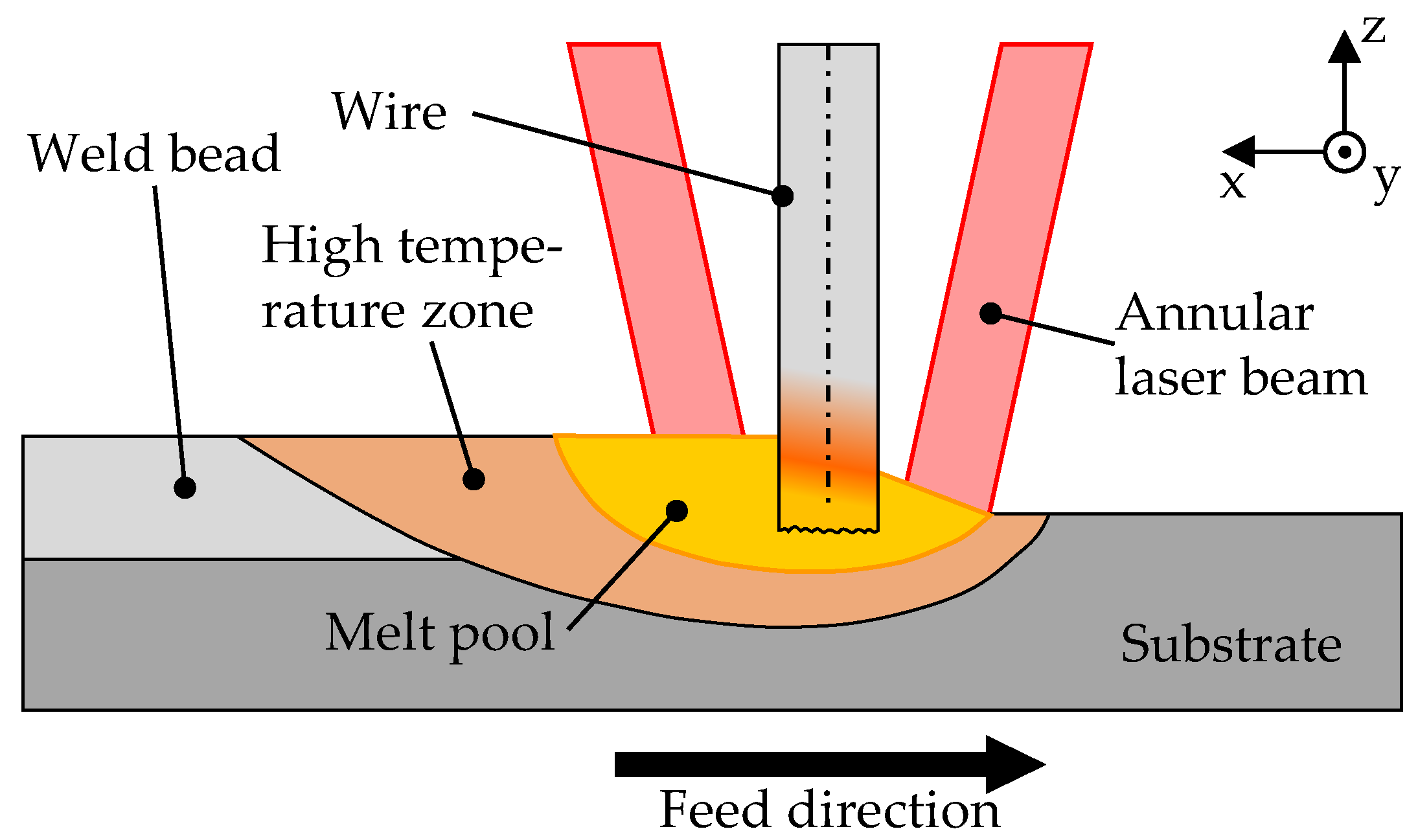
Figure 1. Schematic illustration of the process zone in laser metal deposition with coaxial wire feeding.
Applsci 13 05121 g001
Figure 2. Contour of the contractions according to Wille [54] with the inlet radius r2, the outlet radius r1, the length of the contraction L, the maximum wall angle to the axis α, and the radius r at a distance x from the nozzle outlet.
Applsci 13 05121 g002
Figure 3. Outlet geometry of the shielding gas nozzle with the circular channels acting as flow straighteners.
Applsci 13 05121 g003
Figure 5. Configurations of the investigated shielding gas concepts: (a) lateral shielding gas nozzle; (b) optimized coaxial shielding gas nozzle.
Applsci 13 05121 g005
Figure 6. Contour plots of the oxygen distribution at a shielding gas flow of 50 l/min: (a) outlet of the optimized shielding gas nozzle as a cross-sectional view; (b) oxygen map on the substrate plane.
Applsci 13 05121 g006
Figure 7. Effect of the shielding gas flow rate on the effective protection length (indicated by the blue markers) on the substrate plane at a stand-off distance of 10 mm obtained from the simulations.
Applsci 13 05121 g007
Figure 8. Surfaces of individual weld beads deposited at shielding gas flow rates ranging from 10 l/min to 70 l/min using (a) the lateral nozzle and (b) the optimized nozzle.
Applsci 13 05121 g008
Figure 9. Influence of the shielding gas flow rate when using the optimized nozzle on the weld bead width w and the weld bead height h; the error bars show the respective standard deviation.
Applsci 13 05121 g009
Figure 10. Influence of the shielding gas flow rate when using the optimized nozzle on the average melt pool temperatures Tm during the stationary phase of the process and the coefficients of variation cv of the melt pool temperature signals.
Applsci 13 05121 g010
Figure 11. (a) Multi-track multi-layer cuboid deposited using the optimized shielding gas nozzle; (b) one half of a cross-section of the deposited cuboid.
Applsci 13 05121 g011
Figure 12. EDS line scan of the oxygen distribution in the built-up cuboid along the z-direction.
Applsci 13 05121 g012
Figure 13. Microhardness distribution of the built-up cuboid along the z-direction at the center and the lateral regions.
Applsci 13 05121 g013
Table 1. Parameters describing the geometry of the contraction.
ParametersUnitAdapterNozzle
Inlet radius r1mm47.118.0
Outlet radius r2mm18.07.5
Length Lmm61.030.0
Contraction ratio σ6.855.76
Maximum angle αmax°42.934.4
Table 2. Chemical composition of the wire and the substrate material (wt%).
ElementCrNiMoMnSiCPSFe
Wire18.212.12.51.80.88<0.010.0240.010Bal.
Substrate17.0–19.08.0–11.0≤2.0≤1.0≤0.07≤0.035≤0.03Bal.
Table 3. Process parameters for the deposition of individual weld beads and a cuboid.
ParametersUnitSingle TracksCuboid
Laser power PLW15001200
Traverse speed vtm/min1.01.0
Wire feed rate vwm/min1.01.1
Focal position fmm−6−6
Shielding gas flow rate fsl/min10–7040
Disclaimer/Publisher’s Note: The statements, opinions and data contained in all publications are solely those of the individual author(s) and contributor(s) and not of MDPI and/or the editor(s). MDPI and/or the editor(s) disclaim responsibility for any injury to people or property resulting from any ideas, methods, instructions or products referred to in the content.