Article

Optimal Design of the Laparoscopic Grasper Mechanism with Low Friction and Backlash

1
Faculty of Mechanical Engineering, Technical University of Košice, 042 00 Košice, Slovakia
2
Faculty of Mechanical Engineering, University of J. E. Purkyně, 400 96 Ústí nad Labem, Czech Republic
*
Author to whom correspondence should be addressed.
Appl. Sci. 2023, 13(8), 4997; https://doi.org/10.3390/app13084997
Submission received: 31 January 2023 / Revised: 7 April 2023 / Accepted: 11 April 2023 / Published: 16 April 2023
(This article belongs to the Section Mechanical Engineering)

Abstract

:
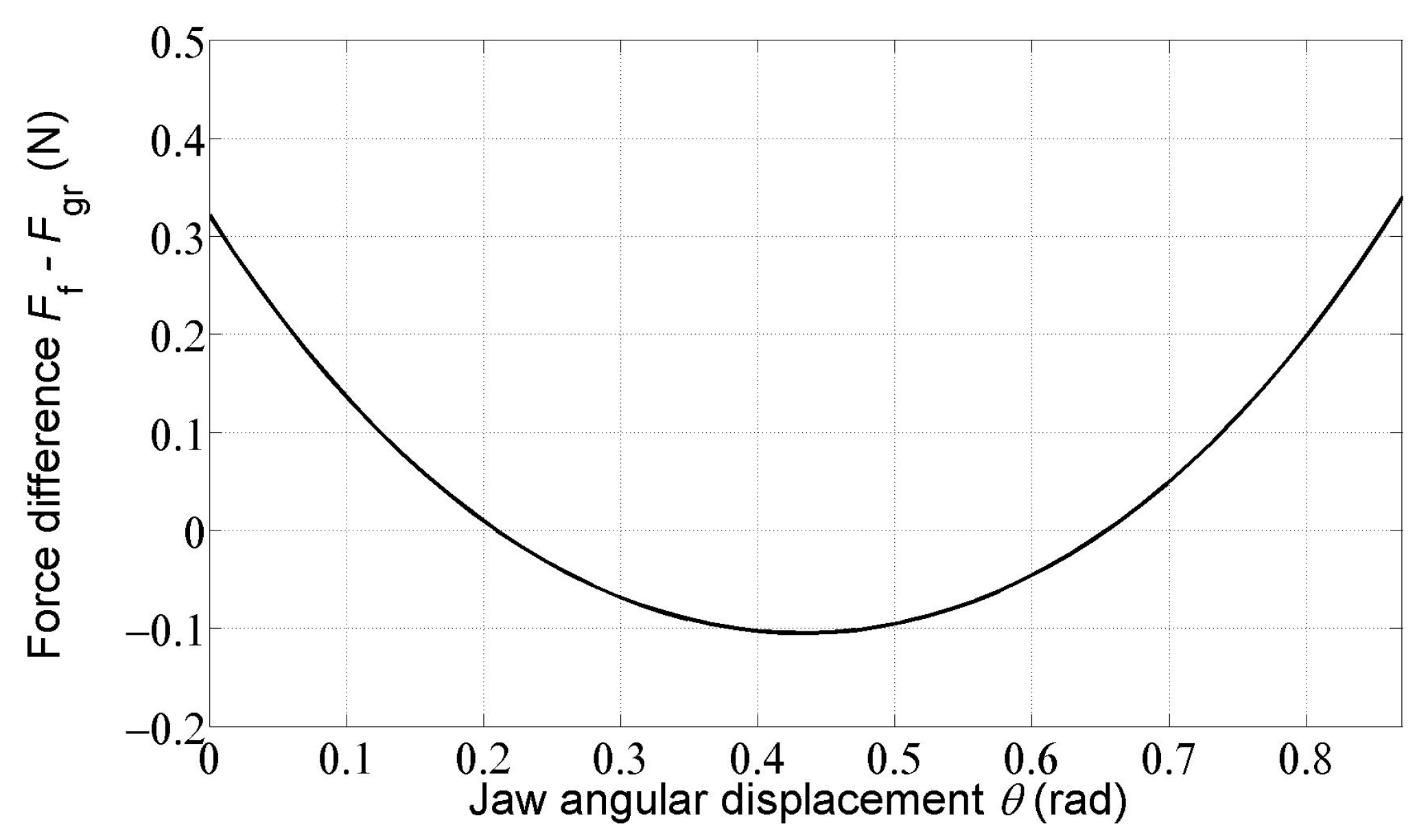
Nowadays, the remote technique of minimally invasive surgery is a popular surgical method due to its established benefits to patients compared with conventional open surgery. However, the surgeon’s only contact with the operated tissue or organ is through his instrument, so he feels less. This study focuses on the numerical optimization of the laparoscopic grasper mechanism designed at the TU Delft to achieve its best mechanical properties. The design of the laparoscopic grasper mechanism is based on the rolling kinematic pairs distinguished by minimum friction and backlash compared to the conventional revolute kinematic pairs. Optimization is aimed at the constant force transmission from the handle to the jaw of the laparoscopic grasper mechanism, independent of the position of the grasper jaw. Constraints on potential energy stored in the driving and compensation springs, their location, and axial force in the connecting rod of the laparoscopic grasper mechanism are taken into account. The outputs of the laparoscopic grasper mechanism optimization show that it is possible to achieve the force transmission from the handle to the jaw of the grasper close to 1, satisfying all constraints. The root mean square of the differences between the force acting on the grasper handle and the grasping force acting on the movable jaw in its whole angular position interval is 0.1112 N. The maximum difference between these two forces is less than 0.35 N (3.5 % of the 10 N grasping force) at the beginning and at the end of the jaw angular displacement interval. In 70% of the whole jaw angular displacement interval, except the 15% subintervals, with the lowest and highest angular displacements of the grasper jaw, the force difference is even less than 0.1 N.

1. Introduction

Laparoscopic surgery, which is a minimally invasive surgery (MIS) method, began to increase in the early 1990s. It is currently a popular operating technique, whereby surgeons access the body cavities by a small incision instead of a single large one. Tissue manipulation is carried out by special surgical instruments for grasping, holding, cutting, squeezing tissue or a body organ, and suturing. The surgical area is reached through a tiny incision of 3 to 15 mm in width, which is broached through the abdominal wall of the patient over their inflated abdominal cavity. MIS is a type of surgery that minimizes the unnecessary invasion of healthy tissues. It has a number of benefits over traditional open surgery—less postoperative pain owing to the small wound, lower risk of infection, less drug usage, early recovery after the surgical operation leading to shorter hospitalization time, and reduced scarring [1,2,3,4]. The current technology of MIS involves the visualization of the surgical area via video cameras.
However, laparoscopic surgery has some significant disadvantages compared to open surgery. The laparoscopic instruments are the only means of contact between the tissue or a body organ and the hands of surgeons. That is why these instruments should be well designed—the pinching force on the surgeon’s hand should be a reliable measurement for the grasping force on the grasper jaws. The vision is obtained through incisions in the abdominal walls of the patients using a video camera. The degree of freedom of the laparoscopic instruments limits the surgical working space. In addition, the tactile information such as tissue stiffness and applied force on the tissue is reduced.
In the MIS operation, tactile sensing (haptic feedback) is only achieved indirectly through the laparoscopic mechanism. The surgeon’s perception of the grasping force may differ from the actual grasping force at the grasper—tissue contact. It increases the risk of injury or damage to the tissue or a body organ due to the excessive force applied by the surgeon. Thus, force feedback is of great importance in laparoscopic surgery.
Laparoscopic instruments can be divided into three main groups: purely mechanical instruments, compliant laparoscopic instruments, and laparoscopic instruments with sensors and electronic feedback.
The most important scientific works in the field of mechanical laparoscopic graspers include the works of J. L. Herder and his collaborators mainly from TU Delft. In the paper [5], the purely mechanical design of a laparoscopic grasper with constant force transmission is presented. There are no standard hinges in the mechanism. It possesses just six rolling kinematic pairs, resulting in very low friction, hysteresis, and substantially reduced backlash. The constant force transmission is achieved through the use of a symmetrical design. The paper [6] is dedicated to the ways of improving the force transmission in laparoscopic grasping instruments by adjusting existing instruments or by designing alternative concepts. The paper [7] presents newly designed, purely mechanical laparoscopic forceps and describes the evaluation of the man–machine interface performance.
Another group of laparoscopic instruments is compliant laparoscopic instruments. Moreover, in this field, the scientific works of J. L. Herder and his collaborators, from different countries, are among the most important. Herder and van den Berg [8] were the first to propose the concept of statically balanced compliant mechanisms and studied a compliant mechanism of surgical forceps, which is statically balanced by a low-friction rolling-link compensation mechanism. This mechanism substantially improved the quality of the transmission between the input and output force at the jaws of the grasper, which is negatively affected by the strain energy accumulated by the elastic members of the compliant mechanism. The possibility of extending the building block approach for the design of statically balanced compliant mechanisms is investigated in [9]. The feasibility of the method is demonstrated in a design of a statically balanced compliant gripper. In [10], a concept, as well as mathematical and finite element modeling of a statically balanced compliant laparoscopic grasper, is presented. This concept not only provides a compliant grasper, which does not need lubrication and avoids friction and energy loss, but it also provided force feedback to eliminate the incorrect laparoscopic pinch force control and tissue damage. A conceptual design and simulation results for two classes of statically balanced compliant micromechanisms are presented in [11]. The authors in [12] presented five criteria that can be used in the static balancing of compliant mechanisms. Their feasibility was proved by three examples using linkages with torsion springs. In the book [13], the author deals with the problem of statically balanced compliant mechanisms. Static balancing eliminates the need for actuation forces besides those required to overcome the inertia and friction of the system. This work has its origins in the work of J. L. Herder. During his research in the field of the static balancing of mechanisms using springs, he came up with the idea of applying the same design notion to compliant mechanisms since the flexible elements can be considered as springs. The design of a statically balanced, monolithic, and fully compliant surgical grasper exhibiting equal or better force feedback than conventional surgical graspers is presented in [14]. The use of the pseudo-rigid-body model is shown here for the first time. The case study by Wang et al. published in [15], presents the numerical model and physical prototype of a statically balanced compliant mechanism. It has a nearly zero actuation force during axial deformation owing to a balancer.
The third group is laparoscopic instruments with sensors and electronic feedback. The paper [16] reviews the state-of-the-art force and tactile sensing methods and technologies applied in MIS. Several sensing strategies, e.g., displacement-based, current-based, pressure-based, etc., are analyzed. A novel design of an electromechanical grasper enhancing its force-reflecting capability is presented in [17]. A substantial part of the grasper is a tunable spring with optimized haptic and surgical requirements. The tunable spring needs a relatively small motor to be actuated. In [18], local sensors are used to give force feedback, which helps to prevent exceeding forces from causing tissue damage. Obtaining the grasping force by its calculating from the sensor-distributed pressure measurement leads to new control methods [19,20]. The study [21] focuses on the grasping of a laparoscopic mechanism in order to control the grasping force by using a smart material actuation. The grasper force is controlled through a smart actuator by two types of controllers—the proportional-integral-derivative (PID) and sliding mode controller (SMC). The smart actuator contains a bias spring and a shape memory alloy wire in order to meet the force and displacement requirements. The authors in [22] proposed a laparoscopic grasper driven by inflating a soft pneumatic actuator. At the tip of the grasper, there is a small cylinder with a pneumatic actuator made of silicone and a slider-crank mechanism. The actuator has a built-in strain gauge to measure its displacement. By combining the measurements of the strain gauge and the internal pressure in the pneumatic actuator, it can estimate the grasping force. The paper [23] presents an estimation of grasping force by exploiting the transmission model of the laparoscope surgical robot end-effector with a cable-pulley structure, which considers friction loss between adjacent pulleys. In the study [24], the authors propose a pneumatic system with a novel small soft rotary actuator for a multi-DOF forceps manipulator. The cylindrical cam mechanism transforms the linear motion of the soft actuator into rotary motion. Using the proposed mechanism, the rotation angle can be pressure controlled without being affected by the forceps’ posture, even when mounted on the forceps’ tip. The authors of the paper [25] tested the effects of improved haptic feedback on force control, interpreting the tissue consistency and the surgeon’s level of confidence.
The study [26] presented a new handle for laparoscopic instruments. The main novelty of this handle is that the opening and closing motion of the grasper is operated with the thumb using a lever located on the top of the handle. This avoids the use of rings for the fingers for holding or activating the laparoscopic instrument. It reduces the pressure and also pain in the surgeons’ hands and fingers. The new handle has a pistol shape to reduce the edges and small contact zones. Tissue clamping and dragging operations in MIS were simulated in [27] by using compress and friction testing under different clamping forces and dragging speeds.
The work presented in this paper is part of the first author’s broader focus on the optimization of mechanical and mechatronic systems, as shown in the following review of the selected papers.
In the paper [28], it is shown that finding numerical values of selected optimization parameters for optimal static balancing of a parallelogram robot mechanism with 6 degrees of freedom and two spring balancing mechanisms can be formulated as an optimization problem. A substantial reduction in the gravitational load on the driving joints is important for reducing the power of the driving servomotors and also leads to simpler and more efficient control systems. The optimization problem was first solved using the Monte Carlo method with interactive reduction of the allowable intervals of the optimization parameters, as described in [29]. The problem was also solved using genetic algorithms, which led to faster and more accurate computations [30]. In [31], the static balancing of different types of mechanisms using spring balancing mechanisms was investigated. The use of a spring balancing mechanism provided a constant force for balancing parallelogram mechanisms of robots and handling devices is presented. Attention was also given to the possibility of balancing robots with variable loads. The objective function expresses the minimization of the driving force effects in the driving joints. For the numerical implementation of the calculations, Matlab optimization toolboxes: Optimization Toolbox For Use with Matlab, version 5.1, Global Optimization Toolbox For Use with Matlab, version 3.1, and also the GOOD (Generator Of Optimal Designs) program [32] were used. In the paper [33], a matrix method of the mechanism kinematic analysis method was used for the dimensional optimization of a wheel loader mechanism. The objective function expresses the minimization of the rotation of the wheel loader bucket during its stroke.
The authors in [34] investigated the oscillation of a horizontal excavator cabin platform with two degrees of freedom with passive, idealized semiactive, and magnetorheological suspension. Its parameters are optimized in a time domain with an objective function expressing the minimization of two conflicting requirements—the frequency-weighted rms value of the platform acceleration and the rms value of the relative displacement between the platform and the excavator cabin. In [35], modeling, control, and optimization of the semiactive suspension of a work machine seat with an air spring and the magnetorheological damper are presented. Three control algorithms—skyhook control, balance control, and their combination—are used to determine the required force of the semiactive damper. The objective function is the rms of the seat acceleration.
This study focuses on the optimization of the laparoscopic grasper mechanism equipped with rolling kinematic pairs [5] with objective function expressing the constant force transmission from the handle to the jaws of the grasper, considering constraints on potential energy stored in the laparoscopic mechanism springs, and some forces in the mechanism links and kinematic pairs. In fact, no such optimization works appear in the literature on laparoscopic mechanisms. However, without them, it is impossible to achieve optimal mechanical properties of this geometrically quite complex mechanism containing two springs—in particular, constant force transmission taking into account various constraints. However, the design of the laparoscopic grasper addressed in this work differs from the laparoscopic grasper presented in [5]. It has flat (not circular) surfaces along which rollers 3 and 4 are rolling, and instead of the second connecting rod between the two rollers, two springs are used—a driving spring 8 and a compensating spring 9 (Figure 1). This design is well suited to present the possibilities of numerical optimization using the Matlab program and its optimization toolboxes. The presented optimization methodology can also be used to optimize various other laparoscopic mechanisms.

2. Kinematics of the Laparoscopic Grasper Mechanism

Figure 1 represents a schematic view of the laparoscopic grasper mechanism. The design is based on a rolling-link type mechanism with a single-sided movable jaw (3) attached to a roller (2). A movable handle (5) is fixed to another roller (4). The two rollers of the same radius are placed opposite each other against two plane support areas on the frame (1), one at each end of the frame (1). The connecting rod (6) connects these rollers by means of bearing housings (7). The grasper mechanism contains two springs—the driving spring (8) and the compensation spring (9).
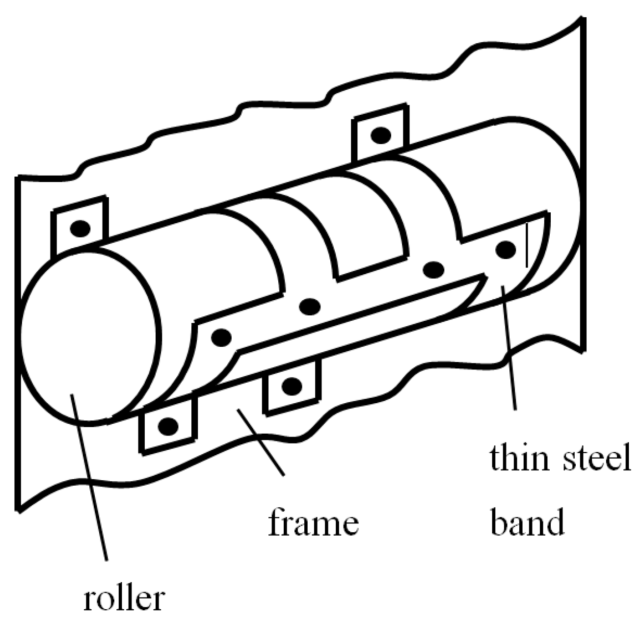
To prevent the rollers (2) and (4) from slipping, flexible bands are wrapped around them (Figure 2). The thin flexible steel bands keep the rollers in position and enable the arising tangential force needed for rolling the rollers. Since all the moving elements roll, the friction in both rolling kinematic pairs is minimal. The pivots at the ends of the connecting rod (6) are also designed to roll—the contact areas are furnished such that the pins fixed to the rollers roll on the inside of an imaginary ring keeping these pins at a constant distance.
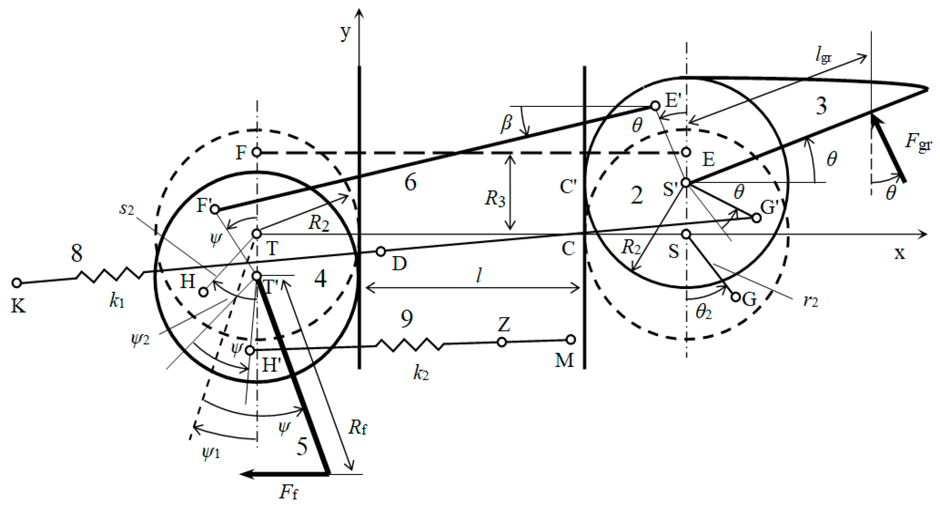
In order to determine the dependence of the force F f , exerted by the surgeon’s finger on the grasper handle, and on the force F gr acting on the movable jaw, solving the kinematics of the grasper mechanism is first needed (Figure 3). It means the determination of the angular coordinate β , determining the angular position of the connecting rod, and the angular coordinate ψ determining position of the roller 4.
To solve the kinematics of the grasper mechanism, the polygon formed by points S, S’, E’, F’, T’, T, and S will be used. Projections of the polygon sides on the x and y axes, Figure 3, gives two nonlinear equations that can be written in the form:
x : R 3 sin θ ( l + 2 R 2 ) cos β + R 3 sin ψ + l + 2 R 2 = 0 ,
y : R 2 θ + R 3 cos θ ( l + 2 R 2 ) sin β R 3 cos ψ + R 2 ψ = 0 .
From these two equations, the dependence of the coordinates β and ψ on the independent coordinate θ , to determine the angular position of the movable jaw 2, can be determined using Matlab.
Equations (1) and (2), see also Figure 3, are:
  • θ —coordinate determining the position of the roller (2),
  • ψ —coordinate determining the position of the roller (4),
  • θ 2 and r 2 —quantities determining the position of point G on the roller (2),
  • ψ 2 and s 2 —quantities determining the position of point H on the roller (4),
  • ψ 1 —coordinate determining the initial position of the handle (5) for φ = 0 .

3. Statics of the Laparoscopic Grasper Mechanism

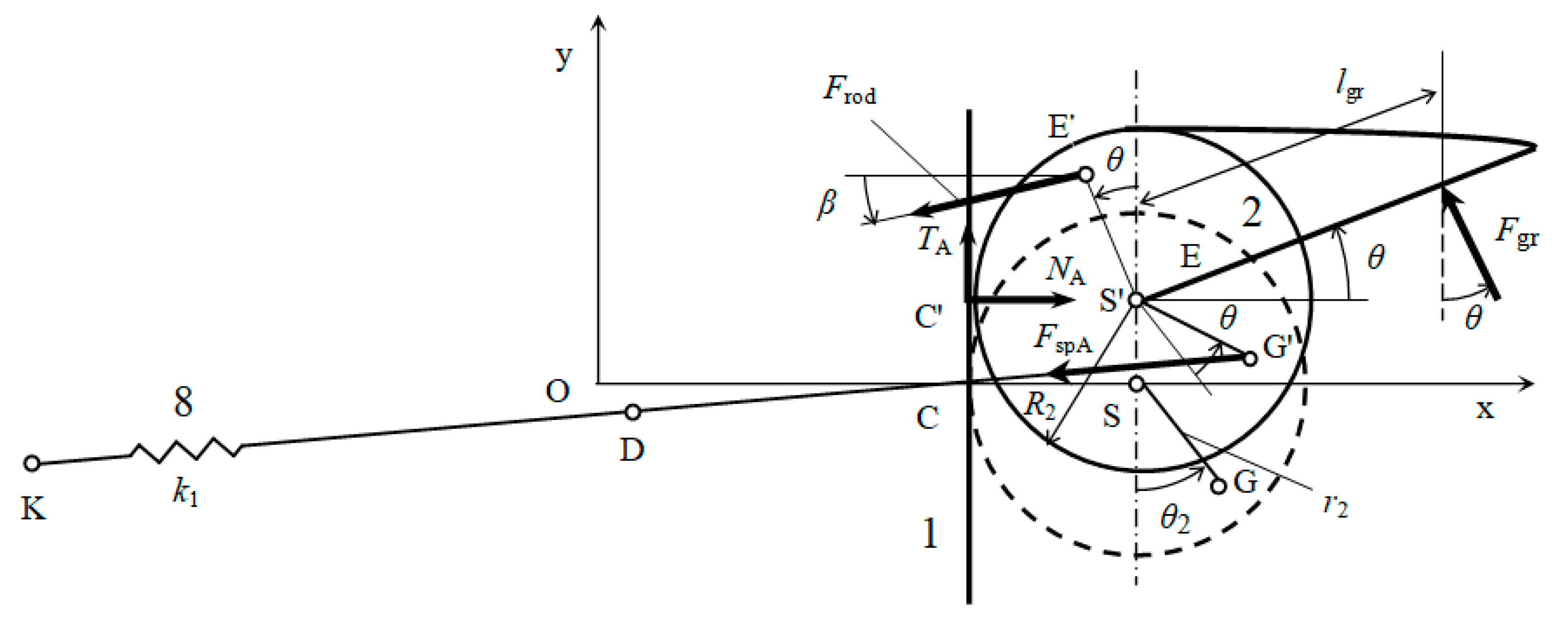
Using free body diagrams of rollers 2 and 4, equations of their static equilibrium can be derived in the form roller (2) with the jaw, Figure 4:
x : N A F rod cos β F gr sin θ F spA x G x K l G = 0 ,
y : T A F rod sin β + F gr cos θ F spA y G y K l G = 0 ,
M C : F gr l gr + R 2 cos θ + F rod cos β R 3 cos θ F rod sin β R 2 R 3 sin θ F spA x G x K l G r 2 cos θ 2 + θ F spA y G y K l G R 2 + r 2 sin θ 2 + θ = 0 ,
where F rod is the axial force in the connecting rod (6), F gr is the force acting on the movable jaw, N A is the normal force between the roller (2) and the frame (1), and T A is the tangential force in the flexible steel band of the roller (2).
The distance between points G′ and K is:
l G = x G x K 2 + y G y K 2 ,
and the force in the driving spring F spA is:
F spA = k 1 l G l 10 l 1 L ,
where k 1 is the driving spring stiffness coefficient, l 10 is its free length, and l 1 L is the length of the cable between points D and G′.
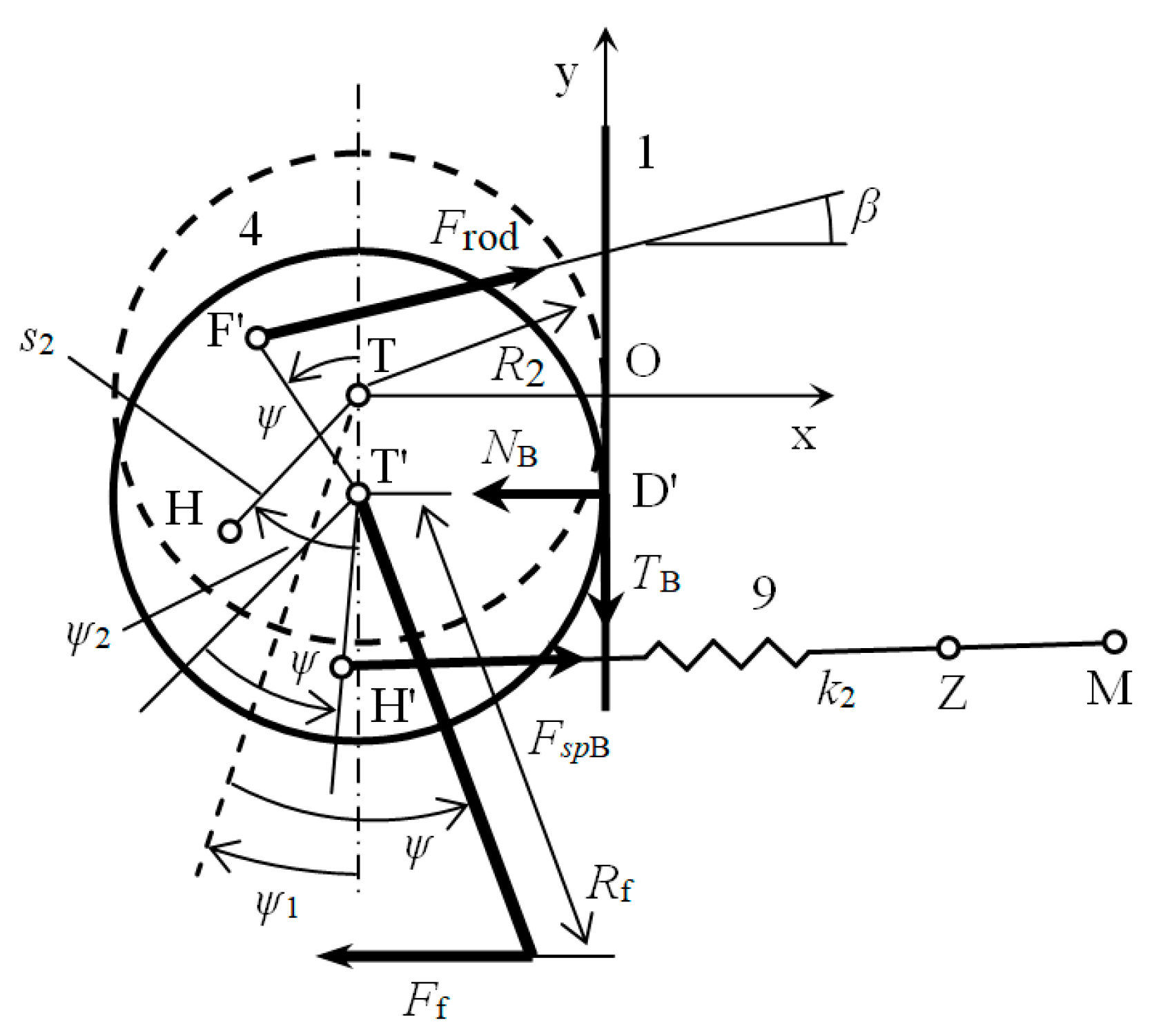
Roller (4) with the handle, Figure 5:
x : N B + F rod cos β F f + F spB x M x H l H = 0 ,
y : T B + F rod sin β + F spB y M y H l H = 0 ,
M D : F f R f cos ψ ψ 1 + F rod cos β R 3 cos ψ + F rod sin β R 2 + R 3 sin ψ F spB x M x H l H s 2 cos ψ 2 ψ + F spB y M y H l H R 2 + s 2 sin ψ 2 ψ = 0 ,
where F f is the force acting from the surgeon’s finger on the handle, N B is the normal force between the roller (4) and the frame (1), and T B is the tangential force in the flexible steel band of the roller (4).
The distance between points H′ and M is:
l H = x M x H 2 + y M y H 2
and the force in the compensation spring F spB is:
F spB = k 2 l H l 20 l 2 L ,
where k 2 is the compensation spring stiffness coefficient, l 20 is its free length, and l 2 L is the length of the cable between points M and Z.

4. Elastic Potential Energy of the Springs of the Laparoscopic Grasper Mechanism

The grasper mechanism includes a set of two springs that balance each other (Figure 3). They produce the forces that keep the rollers in contact with the mechanism’s frame (1). If the static balance of the grasper mechanism is ideal, it will seem to a surgeon as if the springs are not present. Nevertheless, the springs prestress and stabilize the grasper mechanism, thus, eliminating backlash. If an object is grasped with a certain grasping force, the reaction of this force F gr acting on the movable jaw disturbs the balance of forces. Balance is restored by applying an operating force F f acting on the movable handle. Owing to the low-friction mechanism, the operating force F f can be, after optimization, an accurate measure of the grasping force F gr .
The elastic potential energy of the driving spring (8) can be expressed in the form:
V A = 1 2 k 1 l G l 10 l 1 L 2 ,
where the length l G is determined by Equation (6) and the lengths l 10 and l 1 L are described above. Remark: the driving spring will be prestressed in its initial position determined by the angular displacement θ = 0 by at least 15% of the maximum force in this spring for θ = θ max ,  Figure 3. The angle θ max determines the maximal opening of the grasper jaws.
The elastic potential energy of the compensation spring is:
V A = 1 2 k 1 l G l 10 l 1 L 2 ,
where the length l H is determined by Equation (11) and the lengths l 20 and l 2 L are described above.
The total elastic potential energy is the sum of the potential energies of the driving and compensation springs:
V B = 1 2 k 2 l H l 20 l 2 L 2 ,
Furthermore, the compensation spring will be prestressed in its initial position, determined by its minimal length, and determined by the angular displacement of the roller (4) ψ = ψ max by at least 15% of the maximum force in this spring for ψ = 0 , Figure 3.

5. Formulation of the Optimization Problem

The objective function is the root mean square of the differences between the force acting on the handle F f , i and the grasping force F gr , Figure 3, in the whole angular position interval of the movable jaw θ 0 , θ max . In other words, the objective function expresses the quality of the force transmission from the grasper handle to the jaw:
f op = i = 1 N ( F f , i F gr ) 2 N ,
where F f , i is the force in the points of the movable jaw angular position interval ( i = 1 , 2 , , N ) .

5.1. Constraints of the Optimization Problem

The following constraints will be taken into account:
(a)
Constraint on the elastic potential energy of the mechanism springs:
V i V max , i = 1 , 2 , , N ,
where V max is the maximum allowable potential energy of the mechanism springs.
(b)
Constraint on the axial force in the connecting rod:
F rod , i F rod , max , i = 1 , 2 , , N ,
where F rod , max is the maximum allowable force in the connecting rod.
Remark: constraints on some other quantities, e.g., the tangential forces in the flexible steel bands T A and T B , the normal forces in the contact points between the rollers and frame of the laparoscopic grasper N A and N B (Figure 4 and Figure 5), etc., can also be taken into account.

5.2. Variables of the Optimization Problem

Design Variables
The following variables were chosen as the appropriate design variables (Figure 3):
  • r 2 , θ 2 —design variables determining the position of point G on the roller (2),
  • s 2 , ψ 2 —design variables determining the position of point H on the roller (4),
  • x K , y K —design variables determining the position of point K on the mechanism’s frame,
  • x M , y M —design variables determining the position of point M on the frame,
  • c d , c c —prestress coefficients of the driving and compensation springs.
Computed Variables
The lengths DG ¯ and ZM ¯ , Figure 3, are considered computed variables. They will be recomputed in each optimization step.
Specified Variables, see Figure 3 where needed:
  • k 1 = 3910   N / m —stiffness coefficient of the driving spring,
  • k 2 = 3910   N / m —stiffness coefficient of the compensation spring,
  • θ min = 0 —minimum value of the angular coordinate determining the position of the grasper jaw,
  • θ max = 50 —maximum value of the angular coordinate determining the position of the grasper jaw,
  • N = 50 —number of points of the movable jaw position interval ( i = 1 , 2 , , N ) ,
  • l = 0.3   m —length,
  • R 2 = 0.0035   m —radius of the rollers (2) and (4),
  • R 3 = 0.002   m —length,
  • l gr = 0.015   m —length,
  • R f = 0.025   m —length of the handle,
  • F gr = 10   N —force acting on the movable jaw,
  • l 10 = 0.0742   m —free length of the driving spring,
  • l 20 = 0.0742   m —free length of the compensation spring,
  • V max = 3   Nm —maximum allowable elastic potential energy in the springs,
  • F rod , max = 12   N —maximum allowable compression force in the connecting rod,
  • ψ 1 = 25 —angle determining the handle’s initial position.

6. Methods of Solution of the Optimization Problem

To find a constrained minimum of the scalar objective function (16), with ten design variables, first the function fmincon was used [36]. To increase the probability of finding the global and not just the local minimum of the objective function, five different starting points were used because the fmincon function uses a deterministic method to find the minimum. The fmincon function uses the sequential quadratic programming (SQP) method, in which this function solves a subproblem of the quadratic programming in each optimization iteration. SQP, as one of the best optimization methods, is based on solving a system of nonlinear equations using Newton’s method.
However, the ga function for constrained optimization using genetic algorithms (GA) was also used to find the minimum of the objective function (16). It is a stochastic method, based on the principles of natural genetics and natural selection with reproduction, crossover, and mutation as the basic elements [37,38,39]. The method is able to find the global minimum of an objective function with a high probability. It is suitable for solving complex engineering problems with a higher number of design variables.
GA, unlike deterministic methods, uses a population of points for starting the genetic search procedure. Therefore, GA is less likely to get trapped at a local minimum. GA does not use the derivatives of the objective function; it uses just values. The design variables are represented as strings of binary variables that correspond to chromosomes in natural genetics. The GA search method can be used to solve not only discrete but also integer programming problems.

7. Results of Optimization and Discussion

In Table 1, the search intervals for all design variables are given. A minimum for the objective function (16) was found in the given search intervals for the ten design variables by using the function fmincon [36]. The results were the same for all initial estimates. They were checked by the function ga [37].
Optimization results (optimum values of the design variables) obtained are as follows:
r 2 , opt = 0.0022   m , θ 2 , opt = 0.069813   rad , s 2 , opt = 0.0038   m , ψ 2 , opt = 1.090381   rad , x K , opt = 0.07 m , y K , opt =   0.05   m , x M , opt = 0.18   m , y M , opt =   0.004   m , c d = 0.15 , c c = 1.721687 .
The minimum value of the objective function (16) is f op = 0.111182   N .
The lower bounds of the following design variables were reached: r 2 ,   x K ,   y M , and c d . Then, the upper bounds of the following design variables were reached: s 2 ,   θ 2 ,   y K , and x M , see Table 1. The optimum values of the design variables are presented above. Theoretically, it would be possible to shift the lower and upper bounds of the active design variables to further reduce the value of the objective function f op , although this would no longer be appropriate from a design point of view.
Figure 6 shows the dependence of the force difference F f F gr on the jaw angular displacement θ . The difference between these two forces is less than 0.35 N (3.5% of the 10 N grasping force). The force difference in the substantial part of the jaw angular displacement interval (70%, except the 15% intervals with the lowest and highest angular displacements of the grasper jaw) is less than 0.1 N or 1% of the 10 N grasping force. It means that the optimized force transmission from the handle to the jaw of the grasper mechanism is very close to 1.
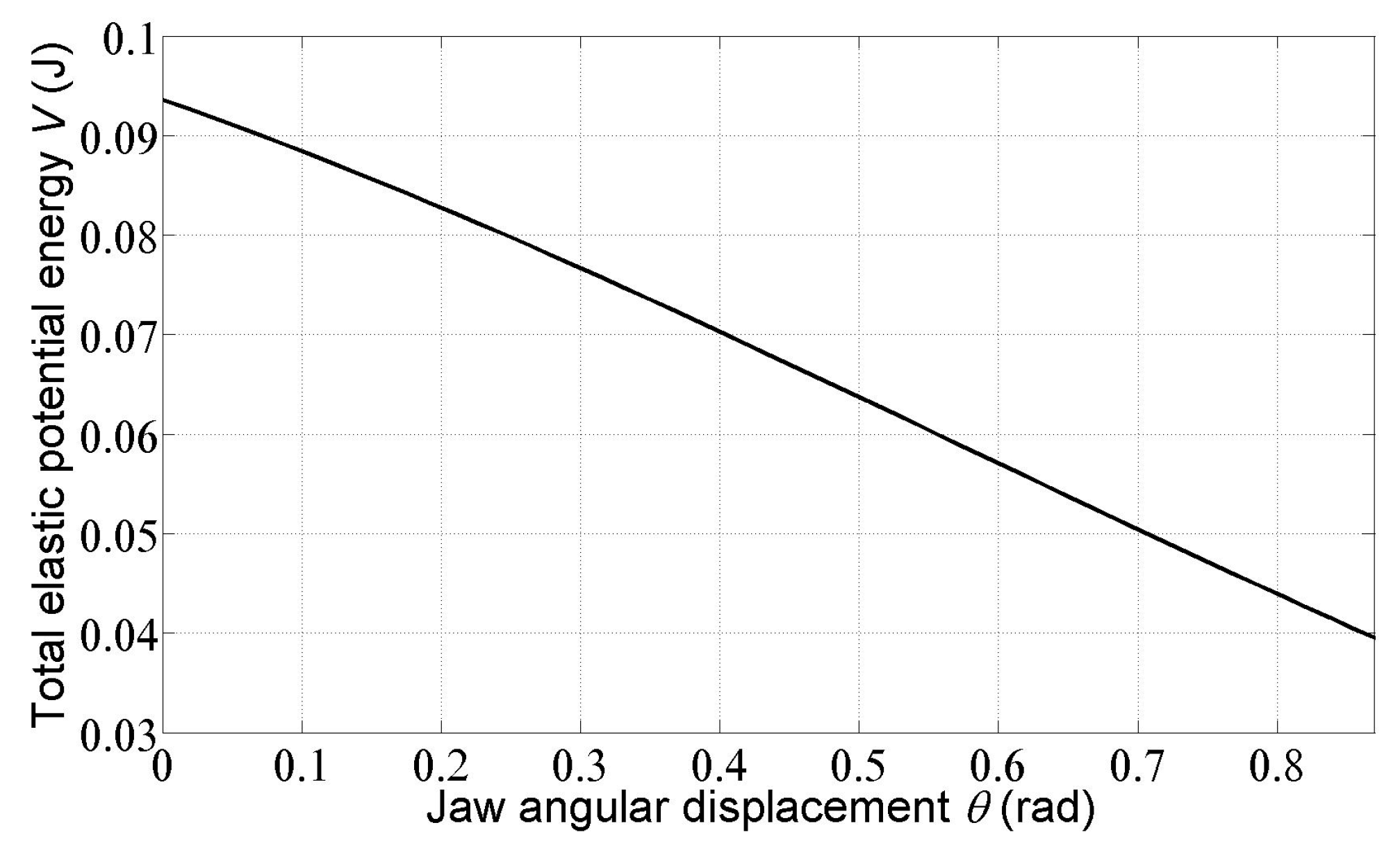
In Figure 7 the dependence of the total elastic potential energy of the driving and compensation springs on the jaw angular displacement θ is shown. It can be seen that the constraint on the maximum elastic potential energy is satisfied. Static balancing of mechanisms—e.g., in the works of J. L. Herder, is based on the assumption of constancy of potential energy (if kinetic energy is zero or a nonzero constant). In the case of the laparoscopic grasper mechanism considered here, although this condition is not satisfied, the force ratio between the grasper handle and its jaw is important and, as can be seen above, is sufficiently close to 1.
The maximum allowable compression force F rod , max in connecting rod 6 was not exceeded, as can be seen in Figure 8. Negative values of this force only mean that there is no tension in this link (as assumed in the free body diagrams of rollers 2 and 4), yet there is compression.
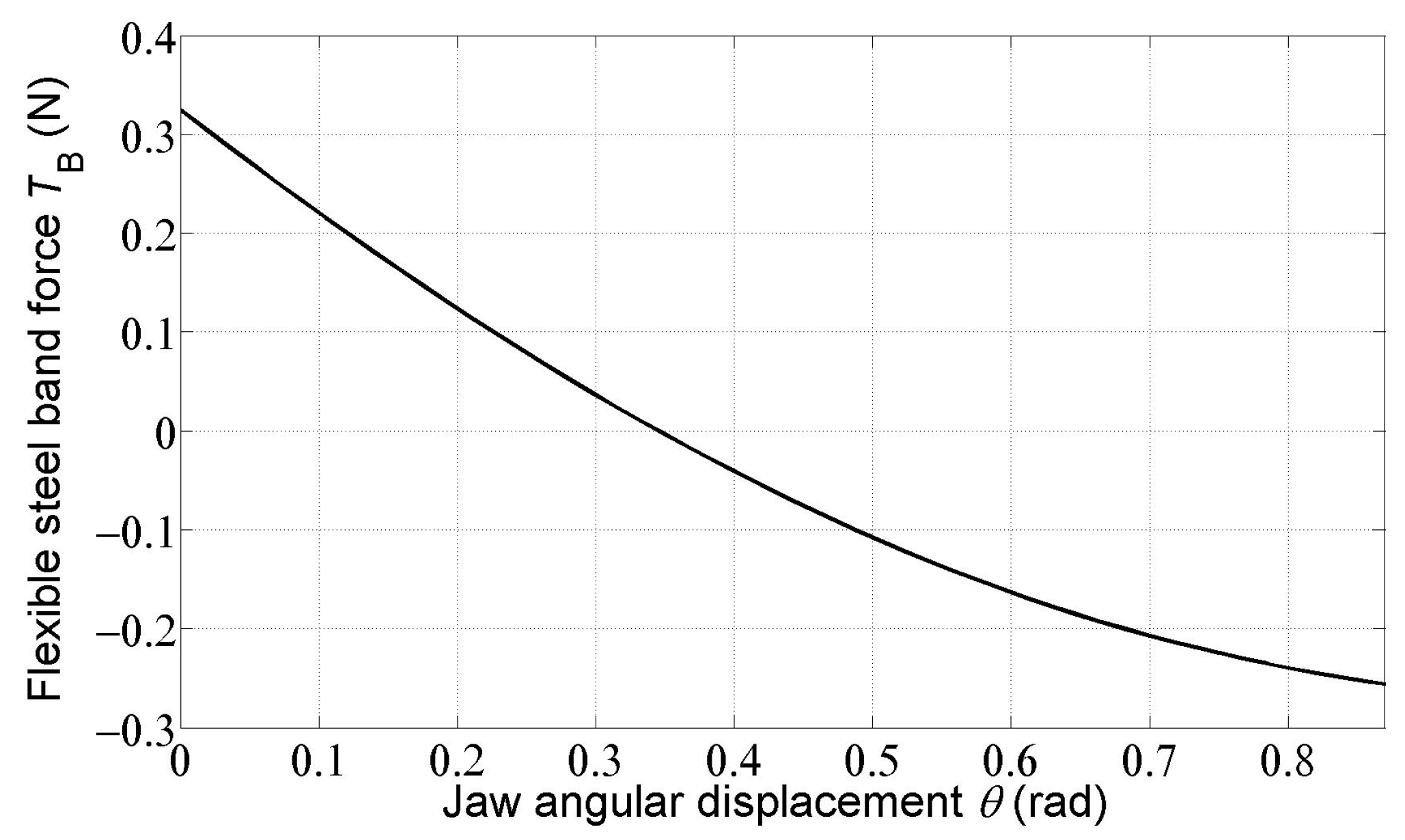
Figure 9 and Figure 10 show the courses of the forces of T A and T B in the flexible steel bands. It can be seen that the T A force acts opposite to what was assumed in the free body diagram of roller 2 (Figure 4). The T B force changes its direction as the rotation of the movable jaw 3 increases (Figure 5).

8. Conclusions

The paper presents possibilities for optimization of the laparoscopic grasper mechanism with low friction and backlash designed at the TU Delft. However, one of the two connecting rods between the handle and the movable jaw is replaced by two springs—a driving and a compensating one. The paper shows a mechanical model of the mechanism, its static and kinematical analysis, choosing appropriate design variables, formulation of an objective function and constraints, and optimization of the chosen design variables. The optimum values of the mechanism were found by using Matlab optimization toolboxes. This optimization procedure can also be applied to the laparoscopic grasper mechanisms with different kinematic structures.
The outputs of optimization of the laparoscopic grasper mechanism show that it is possible to achieve the force transmission from the handle to the jaw of the grasper close to 1, satisfying the applied constraints on the total elastic potential energy in the driving and compensation springs, and on the maximum allowable compression force in the connecting rod.
Interestingly, the purely mechanical rolling-link laparoscopic grasper presented in the first works of J. L. Herder and his collaborators already had a constant force transmission between the handle and the jaw. It would seem that further development of these instruments was no longer necessary. Nevertheless, research, even in the field of laparoscopic instruments, has started to look into the use of compliant mechanisms and also the use of sensors and electronic feedback systems. However, one of the main requirements is again to achieve a constant force transmission between the input and output of these instruments. In the field of compliant mechanisms, this requirement is realized using the concept of static balancing of compliant mechanisms, first presented by Herder and van den Berg. In the field of electronic feedback systems, this requirement is realized using the long-known principles of feedback control.

Author Contributions

S.S.: conceptualization, methodology, modeling, simulation in MATLAB, supervision, and writing—original draft. M.S.: writing—original draft, writing—review and editing, resources, simulation in MATLAB. All authors have read and agreed to the published version of the manuscript.

Funding

This research was funded by the Scientific Grant Agency VEGA of the Ministry of Education, Science, Research and Sport of the Slovak Republic, Grant No. 1/0500/20.

Institutional Review Board Statement

Not applicable.

Informed Consent Statement

Not applicable.

Data Availability Statement

Not applicable.

Acknowledgments

The authors wish to thank the assistant editor and the anonymous referees for their comments, which have helped to improve this paper.

Conflicts of Interest

The authors declare no conflict of interest.

References

  1. Himal, H.S. Minimally invasive (laparoscopic) surgery. Surg. Endosc. 2002, 16, 1647–1652. [Google Scholar] [CrossRef] [PubMed]
  2. Limb, C.; Rockall, T. Principles of laparoscopic surgery. In Reconstructive and Reproductive Surgery in Gynecology, 2nd ed.; Malcolm, G.M., Gomel, V., Eds.; CRC Press: Boca Raton, FL, USA, 2019; Volume 1, pp. 47–72. [Google Scholar] [CrossRef]
  3. Taylor, R.H.; Stoianovici, D. Medical robotics in computer-integrated surgery. IEEE Trans. Robot. Autom. 2003, 19, 765–781. [Google Scholar] [CrossRef]
  4. Ballantyne, G.H.; Leahy, P.F.; Modlin, I.M. Laparoscopic Surgery; WB Sounders Company: Philadelphia, PA, USA, 1994; p. 710. [Google Scholar]
  5. Herder, J.L.; Horward, M.J.; Sjoerdsma, W.A. Laparoscopic grasper with force perception. Minim. Invasive Ther. Allied Technol. 1997, 6, 279–286. [Google Scholar] [CrossRef]
  6. Sjoerdsma, W.A.; Herder, J.L.; Horward, M.J.; Jansen, A.; Bannenberg, J.J.G.; Grimbergen, C.A. Force transmission of laparoscopic grasping instruments. Minim Invasive Ther. Allied Technol. 1997, 6, 274–278. [Google Scholar] [CrossRef]
  7. Herder, J.L.; den Boer, K.T.; Sjoerdsma, W. Design and evaluation of laparoscopic forceps with accurate force feedback. In Proceedings of the 7th IFAC/IFIP/IFORS/IEA Symposium on Analysis, Design and Evaluation of Man-Machine Systems, Kyoto, Japan, 16–18 September 1998. [Google Scholar]
  8. Herder, J.L.; van den Berg, F.P.A. Statically Balanced Compliant Mechanisms (SBCMS): An Example and Prospects. In Proceedings of the ASME 2000 International Design Engineering Technical Conferences & Computers & Information in Engineering Conference, Baltimore, MD, USA, 10–13 September 2000. [Google Scholar]
  9. Hoetmer, K.; Herder, J.L.; Kim, C.J. A Building Block Approach for the Design of Statically Balanced Compliant Mechanisms. In Proceedings of the ASME 2009 International Design Engineering Technical Conferences & Computers & Information in Engineering Conference, IDETC/CIE 2009, San Diego, CA, USA, 30 August–2 September 2009. [Google Scholar]
  10. Tolou, N.; Herder, J.L. Concept and Modeling of a Statically Balanced Fully Compliant Grasper. In Proceedings of the ASME Design Engineering Technical Conference, San Diego, CA, USA, 30 August–2 September 2009. [Google Scholar]
  11. Tolou, N.; Henneken, W.A.; Herder, J.L. Statically Balanced Compliant Micro Mechanisms (SB-MEMS): Concepts and Simulation. In Proceedings of the ASME 2010 International Design Engineering Technical Conferences & Computers & Information in Engineering Conference, IDETC/CIE 2010, Montreal, QC, Canada, 15–18 August 2010. [Google Scholar]
  12. Gallego, J.A.; Herder, J.L. Criteria for the Static Balancing of Compliant Mechanisms. In Proceedings of the ASME 2010 International Design Engineering Technical Conferences & Computers & Information in Engineering Conference, IDETC/CIE 2010, Montreal, QC, Canada, 15–18 August 2010. [Google Scholar]
  13. Gallego Sánchez, J.A.G. Statically Balanced Compliant Mechanisms: Theory and Synthesis. Ph.D. Thesis, Delft University of Technology, Delft, The Netherlands, 9 October 2013. [Google Scholar]
  14. Lamers, A.J.; Sánchez, J.A.G.; Herder, J.L. Design of a statically balanced fully compliant grasper. Mech. Mach. Theory 2015, 92, 230–239. [Google Scholar] [CrossRef]
  15. Wang, S.; Yang, X.; Chen, Y.; Ma, J. A theoretical design of a bellow-shaped staticall balanced compliant mechanism. Mech. Mach. Theory 2021, 161, 163–172. [Google Scholar] [CrossRef]
  16. Puangmali, P.; Althoefer, K.; Seneviratne, L.D.; Murphy, D.; Dasgupta, P. State-of-the-Art in Force and Tactile Sensing for Minimally Invasive Surgery. IEEE Sens. J. 2008, 8, 371–380. [Google Scholar] [CrossRef]
  17. Faraz, A.; Payandeh, S.; Salvarinov, A. Design of a force control grasper through stiffness modulation for endosurgery: Theory and experiments. Mechatronics 2000, 10, 627–648. [Google Scholar] [CrossRef]
  18. Kianzad, S.; Karkouti, S.O.; Taghirad, H.D. Force control of intelligent laparoscopic forceps. J. Med. Imaging Health Inform. 2011, 1, 284–289. [Google Scholar] [CrossRef]
  19. Sümer, B.; Özin, M.C.; Eray, T.; Koç, I.M. The undamaged tissue grasping in a laparoscopic surgical grasper via distributed pressure measurement. Tribol. Int. 2017, 113, 330–337. [Google Scholar] [CrossRef]
  20. Koç, I.M.; Akça, E. Design of a piezoelectric based tactile sensor with bio-inspired micro/nano-pillars. Tribol. Int. 2013, 59, 321–331. [Google Scholar]
  21. Koç, I.M.; Eray, T.; Sümer, B.; Çerçi, N. An active force controlled laparoscopic grasper by using a smart material actuation. Tribol. Int. 2016, 100, 317–327. [Google Scholar] [CrossRef]
  22. Takizawa, T.; Kanno, T.; Miyzaki, R.; Tadano, K.; Kawashima, K. Grasping force estimation in robotic forceps using a soft pneumatic actuator with a built-in sensor. Sens. Actuators A Phys. 2018, 271, 124–130. [Google Scholar] [CrossRef]
  23. Xue, R.; Du, Z.; Yan, Z.; Ren, B. An estimation method of grasping force for laparoscope surgical robot based on the model of a cable-pulley system. Mech. Mach. Theory 2019, 134, 440–454. [Google Scholar] [CrossRef]
  24. Fukushima, K.; Miyazaki, T.; Kawase, T.; Kanno, T.; Sogabe, M.; Nakajima, Y.; Kawashima, K. A pneumatic rotary actuator for forceps tip rotation. Sens. Actuators A Phys. 2022, 333, 113222. [Google Scholar] [CrossRef]
  25. Chantal, C.J.A.; Vleugels, M.P.H.; Coppus, S.F.P.J.; Nieboer, T.E. The effects of laparoscopic graspers with enhanced haptic feedback on applied forces: A randomized comparison with conventional graspers. Surg. Endosc. 2017, 31, 5411–5417. [Google Scholar]
  26. Sancibrian, R.; Redondo-Figuero, C.; Gutierrez-Diez, M.C.; Gonzalez-Sarabia, E.; Manuel-Palazuelos, J.C. Ergonomic evaluation and performance of a new handle for laparoscopic tools in surgery. Appl. Ergon. 2020, 89, 103210. [Google Scholar] [CrossRef] [PubMed]
  27. Li, W.; Jia, Z.; Wang, J.; Shi, L.; Zhou, Z.R. Friction behavior at minimally invasive grasper/liver tissue interface. Tribol. Int. 2015, 81, 190–198. [Google Scholar] [CrossRef]
  28. Segla, S.; Kalker-Kalkman, C.M.; Schwab, A.L. Statical balancing of a robot mechanism with the aid of a genetic algorithm. Mech. Mach. Theory 1998, 33, 163–174. [Google Scholar] [CrossRef]
  29. Kalker-Kalkman, C.M. A design program based on the Monte Carlo method with applications. In Advances in Computer-Aided Engineering; Delft University Press: Delft, The Netherlands, 1994; pp. 61–70. [Google Scholar]
  30. Kalker-Kalkman, C.M.; Offermans, M.F. A general design program based on Genetic Algorithms with applications. In Proceedings of the 21st ASME Design Automation Conference, Boston, MA, USA, 14 September 1995. [Google Scholar]
  31. Segla, S. Static balancing of robot mechanisms and manipulation devices. SC-JME 2018, 68, 77–90. [Google Scholar] [CrossRef]
  32. Kalker-Kalkman, C.M. Optimal design with the aid of randomization methods. Eng. Comput. 1991, 7, 173–183. [Google Scholar] [CrossRef]
  33. Segla, S. Kinematic analysis and optimization of a wheel loader mechanism. Manuf. Technol. 2018, 18, 309–314. [Google Scholar] [CrossRef]
  34. Segla, S.; Musil, M. Comparison of passive and semi-active horizontal platform suspensions. Teh. Vjesn. 2018, 25, 1659–1666. [Google Scholar]
  35. Segla, S.; Kajaste, J.; Keski-Honkola, P. Optimization of Semi-active Seat Suspension with Magnetorheological Damper. In Proceedings of the 10th International Conference on Vibration Problems, Prague, Czech Republic, 7–9 September 2011. [Google Scholar]
  36. Optimization Toolbox. Available online: https://uk.mathworks.com/products/optimization.html (accessed on 3 November 2022).
  37. Global Optimization Toolbox User’s Guide. Available online: https://uk.mathworks.com/help/pdf_doc/gads/gads.pdf (accessed on 4 November 2022).
  38. Goldberg, D.E. Genetic Algorithms in Search, Optimization, and Machine Linearning; Addison-Wesley: Reading, MA, USA, 1989. [Google Scholar]
  39. Rao, S.S. Engineering Optimization Theory and Practice; Wiley: Hoboken, NJ, USA, 2020. [Google Scholar]
Figure 1. Mechanical model of the laparoscopic grasper mechanism.
Applsci 13 04997 g001
Figure 2. Practical realization of the rolling-link type mechanism.
Applsci 13 04997 g002
Figure 3. Kinematical scheme of the laparoscopic grasper mechanism.
Applsci 13 04997 g003
Figure 4. Freebody diagram—roller (2).
Applsci 13 04997 g004
Figure 5. Freebody diagram—roller (4).
Applsci 13 04997 g005
Figure 6. Dependence of the force difference F f F gr on the jaw angular displacement θ .
Applsci 13 04997 g006
Figure 7. Dependence of the total elastic potential energy of the driving and compensation springs on the jaw angular displacement θ .
Applsci 13 04997 g007
Figure 8. Dependence of the axial compression force in the connecting rod F rod on the jaw angular displacement θ .
Applsci 13 04997 g008
Figure 9. Dependence of the flexible steel band force T A on the jaw angular displacement θ .
Applsci 13 04997 g009
Figure 10. Dependence of the flexible steel band force T B on the jaw angular displacement θ .
Applsci 13 04997 g010
Table 1. Design variables with their bounds.
Design VariableUnitsLower BoundUpper Bound
r 2 m0.00220.0034
θ 2 °140
s 2 m0.00280.0038
ψ 2 °2070
x K m−0.07−0.02
y K m−0.03−0.005
x M m0.120.18
y M m−0.0040.004
c d 0.151.8
c c 0.151.8
Disclaimer/Publisher’s Note: The statements, opinions and data contained in all publications are solely those of the individual author(s) and contributor(s) and not of MDPI and/or the editor(s). MDPI and/or the editor(s) disclaim responsibility for any injury to people or property resulting from any ideas, methods, instructions or products referred to in the content.